Embed Size (px)
DESCRIPTION
NSN Whitepaper
Citation preview

Outdoor 3G/LTE Small Cells Deployment Strategy: “The Race to the Pole”
White Paper

2 Outdoor 3G/LTE Small Cells Deployment Strategy
Contents
1. Executive summary .............................................................................3
2. Drivers, Needs and Market Expectations ...........................................4
3. Total Cost of Ownership (TCO) Opportunities ....................................5
4. Driving and Managing Value of Small Cells.... ....................................7
5. Deployment considerations for Outdoor Small Cells.... ....................10
6. Efficient Radio & Management Solutions for Outdoor Small Cells.... 11
6.1 Integration of Small Cells and Macro; Distibuted or
centralized RAN ........................................................................12
7. Efficient Transport Solutions for Outdoor Small Cells.... ...................14
7.1 Wired transport .........................................................................15
7.2 Wireless transport .....................................................................17
8. Conclusion.....................................................................................................20
9. Abbreviations. . ...................................................................................21
Disclaimer: This paper summarizes research and studies conducted by Nokia Siemens Networks. The studies have been performed with the utmost care, and the results are to the best of our knowledge. However, this document cannot be used to derive contractual obligations of any kind.

3Outdoor 3G/LTE Small Cells Deployment Strategy
Within this paper we examine how outdoor small cells can contribute, as part of a carefully coordinated deployment strategy, to meeting the growing data traffic demand in telecommunications while facilitating a 25x reduction in the total cost of ownership for each carried bit (TCO/bit). A combination of macro cell upgrades complemented by 3G and LTE small cells, both indoors and outdoors, is capable of fulfilling anticipated future capacity and service quality demands. Outdoor small cells are required for deployment primarily in dense urban areas, with their deployment levels depending significantly on the service level that operators need to provide to their customers at given locations. While indoor larger locations such as malls, tube/train stations and enterprises would require a dedicated indoor small cell deployment, an outdoor street level small cell network can also help operators provide indoor penetration through up to three interior
walls in the customer trading floor area of the shops, restaurants and cafes in that street. In effect, deploying small cell at street level would be faster, cheaper and much simpler compared to using a small cell for every indoor location.
In summary, viewing outdoor small cell sites simply as slimmed-down macro cell sites does not provide a commercially feasible approach for new deployments. Instead, operators need to adopt a solution-focused, holistic network deployment mindset. They need to make use of opportunities for cost reduction within all areas of network deployment, from professional services through to radio and transport technology optimization. In all scenarios however, the macro site remains the key asset for operators, with outdoor small cells complementing these main sites to ensure required coverage, capacity and service targets can be achieved cost-effectively.
1. Executive summary
4 Outdoor 3G/LTE Small Cells Deployment Strategy
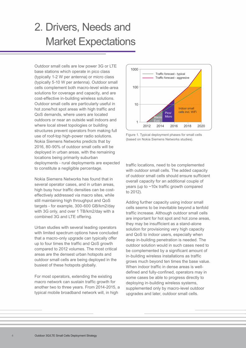
Outdoor small cells are low power 3G or LTE base stations which operate in pico class (typically 1-2 W per antenna) or micro class (typically 5-10 W per antenna). Outdoor small cells complement both macro-level wide-area solutions for coverage and capacity, and are cost-effective in-building wireless solutions. Outdoor small cells are particularly useful in hot zone/hot spot areas with high traffic and QoS demands, where users are located outdoors or near an outside wall indoors and where local street topologies or building structures prevent operators from making full use of roof-top high-power radio solutions. Nokia Siemens Networks predicts that by 2016, 80-90% of outdoor small cells will be deployed in urban areas, with the remaining locations being primarily suburban deployments - rural deployments are expected to constitute a negligible percentage.
Nokia Siemens Networks has found that in several operator cases, and in urban areas, high busy hour traffic densities can be cost-effectively addressed via macro sites, while still maintaining high throughput and QoS targets - for example, 300-600 GB/km2/day with 3G only, and over 1 TB/km2/day with a combined 3G and LTE offering.
Urban studies with several leading operators with limited spectrum options have concluded that a macro-only upgrade can typically offer up to four times the traffic and QoS growth compared to 2012 volumes. The most critical areas are the densest urban hotspots and outdoor small cells are being deployed in the busiest of these hotspots globally.
For most operators, extending the existing macro network can sustain traffic growth for another two to three years. From 2014-2015, a typical mobile broadband network will, in high
traffic locations, need to be complemented with outdoor small cells. The added capacity of outdoor small cells should ensure sufficient overall capacity for an additional couple of years (up to ~10x traffic growth compared to 2012).
Adding further capacity using indoor small cells seems to be inevitable beyond a tenfold traffic increase. Although outdoor small cells are important for hot spot and hot zone areas, they may be insufficient as a stand-alone solution for provisioning very high capacity and QoS to indoor users, especially when deep in-building penetration is needed. The outdoor solution would in such cases need to be complemented by a significant amount of in-building wireless installations as traffic grows much beyond ten times the base value. When indoor traffic in dense areas is well-defined and fully-confined, operators may in some cases be able to progress directly to deploying in-building wireless systems, supplemented only by macro-level outdoor upgrades and later, outdoor small cells.
2. Drivers, Needs and Market Expectations
Figure 1. Typical deployment phases for small cells (based on Nokia Siemens Networks studies).
1
10
100
1000
2012 2014 2016 2018 2020
Macro Evol.
Pico/Micro
Indoor small cells incl. WiFi
Traffic forecast - typicalTraffic forecast - aggresive
5Outdoor 3G/LTE Small Cells Deployment Strategy
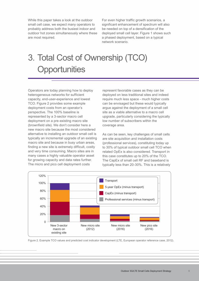
Figure 2. Example TCO values and predicted cost indicator development (LTE, European operator reference case, 2012).
Operators are today planning how to deploy heterogeneous networks for sufficient capacity, end-user-experience and lowest TCO. Figure 2 provides some example deployment costs from an operator’s perspective. The 100% baseline is represented by a 3-sector macro cell deployment on a pre-existing macro site (brownfield site). We don’t consider here a new macro site because the most considered alternative to installing an outdoor small cell is typically an incremental upgrade of an existing macro site and because in busy urban areas, finding a new site is extremely difficult, costly and very time consuming. Macro sites are in many cases a highly valuable operator asset for growing capacity and data rates further. The micro and pico cell deployment costs
represent favorable cases as they can be deployed on less traditional sites and indeed require much less space - much higher costs can be envisaged but these would typically argue against the deployment of a small cell site as a viable alternative to a macro cell upgrade, particularly considering the typically low number of subscribers within the coverage area.
As can be seen, key challenges of small cells are site acquisition and installation costs (professional services), constituting today up to 30% of typical outdoor small cell TCO when related OpEx is also considered. Transport in this case constitutes up to 20% of the TCO. The CapEx of small cell RF and baseband is typically less than 20-30%. This is a relatively
3. Total Cost of Ownership (TCO) Opportunities
While this paper takes a look at the outdoor small cell case, we expect many operators to probably address both the busiest indoor and outdoor hot zones simultaneously where these are most required.
For even higher traffic growth scenarios, a significant enhancement of spectrum will also be needed on top of a densification of the deployed small cell layer. Figure 1 shows such a phased deployment, based on a typical network scenario.
100%
80%
60%
40%
20%
120%
0New 3-sector
macro on existing site
New micro site (2012)
New micro site (2016)
New pico site (2016)
Transport
5-year OpEx (minus transport)
CapEx (minus transport)
Professional services (minus transport)

6 Outdoor 3G/LTE Small Cells Deployment Strategy
small part of overall TCO but represents a significant contribution in driving the value of an outdoor small cell site. Thus, to minimize TCO per subscriber, the overall focus should be on maximizing the number of subscribers successfully served by each deployed small cell solution (individual cell or cell cluster) and on lowering the OpEx of optimization, care and maintenance.
Figure 2 reflects the costs of micro and pico sites over a four year period. Nokia Siemens Networks believes that, compared to today, an average cost reduction of between two and three times is achievable for outdoor small cells. This paper discusses the various related enablers. In fact, where operators take a holistic approach to small cell deployment, Nokia Siemens Networks believes that reduction of the TCO per bit by up to 25-50 times is possible, enabling a more favorable balance between network upgrade costs and the revenue generated from Mobile Broadband. To achieve these cost levels, benefits need to be exploited from all possible domains, including:• optimized delivery of radio capacity and
high data rate coverage; • a focused strategy considering radio
access technology and spectrum in
combined macro and small cell deployments ;
• technology improvements addressing macro and small cell efficiency, energy efficiency and transport efficiency;
• automation and cost-optimized management;
• new business options for transport enabled by e.g. fiber initiatives; and
• streamlining of site acquisition processes, etc.
We show in Figure 3 TCO per GByte assessments for various network upgrade scenarios using three different traffic growth ratios (against a 2012 reference). The Y-axis denotes the percentage of users that do not receive the targeted QoS level for the given network upgrade step (lower is better). The X-axis shows the normalized TCO per GByte (lower is better). The different upgrade steps assume different QoS targets for the network as specified in the figure. It can be seen that the x50 and x100 traffic growth scenarios can be managed only with macro and outdoor small cell upgrades but in these scenarios a large percentage of end-users are likely not to achieve the assumed QoS targets. To reduce the percentage of users receiving services below the assumed targets, indoor solutions
Figure 3. TCO per carried Gbyte evolution versus traffic and QoS growth rate (versus 2012 reference) for different network realizations (dense urban environment, European operator example).
25.0%
20.0%
15.0%
10.0%
5.0%
30.0%
35.0%
0.0%0.1 1
TCO/Gbyte10
Macro + Outdoor Pico
Macro + Outdoor Pico + Indoor Femto
Macro + Outdoor Pico + Indoor WiFi
Use
rs n
ot a
chie
ving
QoS
targ
et
x50 trafficQoS @ 4 Mbps
x4 trafficQoS @ 4 Mbpsx100 traffic
QoS @10 Mbps
25.0%
20.0%
15.0%
10.0%
5.0%
30.0%
35.0%
0.0%0.1 1
TCO/Gbyte10
Macro + Outdoor Pico
Macro + Outdoor Pico + Indoor Femto
Macro + Outdoor Pico + Indoor WiFi
Use
rs n
ot a
chie
ving
QoS
targ
et
x50 trafficQoS @ 4 Mbps
x4 trafficQoS @ 4 Mbpsx100 traffic
QoS @10 Mbps

7Outdoor 3G/LTE Small Cells Deployment Strategy
Site acquisition strategy and planning is a very important factor in optimizing the value-to-cost ratio of outdoor small cells. A first key element in effective site acquisition is to ensure that the optimum number of subscribers benefit from the service delivered by the small cell. Very efficient installations of outdoor small cells deployed in larger cities today are able to capture similar amounts of traffic to a high-powered macrocell.
Nokia Siemens Networks envisages the need for a new and integrated network management framework for small cells that includes tools for automated and intelligent prediction of
capacity growth (where, how much, and when). This would provide a toolbox that exceeds the capabilities of traditional RF Planning by incorporating site design and deployment features seamlessly. Market-specific demand masks could be generated showing capacity hot-zones and hotspots based on user activity and network statistics at the required high resolutions necessary to plan small cells networks and prioritize network resource deployments. All available small cell solutions could be evaluated together, with due consideration given to factors such as site accessibility and backhaul options.
are also needed for both the x50 and x100 traffic growth scenarios.
Figure 3 shows therefore that the need and timing for small cell deployment depends significantly on traffic growth patterns, with the x4 ratios typically seen in the 2015-2016 time-frame calling for outdoor small cells.
However, it is equally important to consider the required data rate and QoS that an operator aims to provide to attract or retain customers at a given location. If the target service level is intended to be, for example, at 1 Mbps – a pretty low target in mature markets - Nokia Siemens Networks’ studies indicate that upgrading macro sites with more spectrum and improved sectorization/antennas can be the most attractive solution, which would then significantly reduce the need for small cells before 2020. If, alternatively, the aim is to provide 4-10 Mbps HD video services for all users – a more likely scenario for most advanced markets - significant deployments of small cells will be
needed during the same time-frame. As such, small cells are expected to be deployed at different rates in different geographical regions and based on the operator’s strategy.
In the studies referred to, the downlink traffic growth ratio is considered to be the main driver for cell densification. Operator network measurements have shown that uplink user throughput is significantly lower in comparison to downlink, often by a ratio of 1:6 but even as much as 1:10 for streaming-dominated networks. However, for cases where there is a more balanced uplink and downlink traffic and QoS requirement (e.g. seen today during dense mass events – see Nokia Siemens Networks paper on Mass Event networks support), the situation will call for a faster adoption of small cells, as this cannot be tackled as efficiently by, for example, simply adding more spectrum to the existing wide area network. This is particularly true for deep indoor coverage, especially where combined with propagation losses at, for example, 2.6 or 3.5 GHz.
4. Driving and Managing Value of Small Cell Sites
8 Outdoor 3G/LTE Small Cells Deployment Strategy
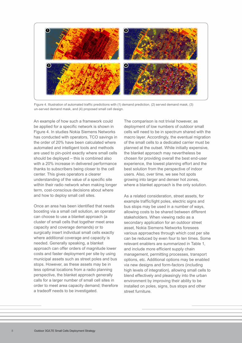
An example of how such a framework could be applied for a specific network is shown in Figure 4. In studies Nokia Siemens Networks has conducted with operators, TCO savings in the order of 20% have been calculated where automated and intelligent tools and methods are used to pin-point exactly where small cells should be deployed – this is combined also with a 20% increase in delivered performance thanks to subscribers being closer to the cell center. This gives operators a clearer understanding of the value of a specific site within their radio network when making longer term, cost-conscious decisions about where and how to deploy small cell sites. Once an area has been identified that needs boosting via a small cell solution, an operator can choose to use a blanket approach (a cluster of small cells that together meet area capacity and coverage demands) or to surgically insert individual small cells exactly where additional coverage and capacity is needed. Generally speaking, a blanket approach can offer orders of magnitude lower costs and faster deployment per site by using municipal assets such as street poles and bus stops. However, as these assets may be in less optimal locations from a radio planning perspective, the blanket approach generally calls for a larger number of small cell sites in order to meet area capacity demand; therefore a tradeoff needs to be investigated.
The comparison is not trivial however, as deployment of low numbers of outdoor small cells will need to be in spectrum shared with the macro layer. Accordingly, the eventual migration of the small cells to a dedicated carrier must be planned at the outset. While initially expensive, the blanket approach may nevertheless be chosen for providing overall the best end-user experience, the lowest planning effort and the best solution from the perspective of indoor users. Also, over time, we see hot spots growing into larger and denser hot zones, where a blanket approach is the only solution.
As a related consideration, street assets, for example traffic/light poles, electric signs and bus stops may be used in a number of ways, allowing costs to be shared between different stakeholders. When viewing radio as a secondary application for an outdoor street asset, Nokia Siemens Networks foresees various approaches through which cost per site can be reduced by even four to ten times. Some relevant enablers are summarized in Table 1, and include more efficient supply chain management, permitting processes, transport options, etc. Additional options may be enabled via new designs and form-factors (including high levels of integration), allowing small cells to blend effectively and pleasingly into the urban environment by improving their ability to be installed on poles, signs, bus stops and other street furniture.
Figure 4. Illustration of automated traffic predictions with (1) demand prediction, (2) served demand mask, (3) un-served demand mask, and (4) proposed small cell design.

9Outdoor 3G/LTE Small Cells Deployment Strategy
An issue closely related to maximizing the value of site investments is adoption of a combined Wi-Fi and LTE deployment strategy. With improved interworking and admission control capabilities emerging between 3GPP and Wi-Fi (e.g. Nokia Siemens Networks Smart Wi-Fi inter Wi-Fi 3GPP RAT traffic steering, ANDSF, Hotspot 2.0), the addition of carrier Wi-Fi to an outdoor small cell site can increase the number of QoS-satisfied users by typically 20-25%. It simultaneously offers a service to new Wi-Fi-only customers and functions as an effective bridge to support the traffic of most 3G and LTE smart phones. Conversely, an existing Wi-Fi outdoor site could be an effective inflection point to add 3GPP small cell technology; although a direct alignment to the Wi-Fi access point (AP) grid would need to be studied. Using a different deployment grid for the 3GPP small cells may provide better overall performance, given that Wi-Fi and 3GPP technologies can be efficiently integrated for consistent end-user QoS provisioning. However, the applicability of Wi-Fi needs to be considered separately for each deployment case. In low-growth scenarios, using Wi-Fi may be relatively expensive, and in very high-growth scenarios, the performance and QoS capability of Wi-Fi for outdoors must be carefully considered.
Similar to some macro networks where cell site grids are aligned between various operators, small cell deployments may also be highly correlated (e.g. the same hot zones and town centers). However, for macro sites, the
installation of equipment from multiple operators is highly feasible. For small cells with limited street level assets and space, the installation of multiple operators’ equipment will likely be prohibited. Therefore, operators should to some extent look at small cell site locations as strategically important “real estate” and consider the timing of their investments – the earlier the better. The first operator to acquire suitable small cell locations may be in a strong position to offer competitive differentiating services. However, it needs to be noted that an optimal site location for one operator may not always be consistent with what is seen as suitable by another, as this will depend very much on spectrum allocation, macro site grids, etc. Such strategies may be clearer for certain indoor centers with large capacity and coverage requirements.
Restrictions on access to small cell sites and potential municipal requirements for equal service access for all residents may entice operators to pursue site sharing arrangements. Such sharing may be at site level or may even entice the use of active RAN sharing options. For this reason, Nokia Siemens Networks’ small cell solution supports sharing of network resources between different operators, including multi-operator radio access network (MORAN) and multi-operator core network (MOCN) sharing. The solution also supports hybrid cases, for instance involving a shared small cell network and non-shared macro networks.
Cost factor Site selected primarily for radio deployment Site where radio deployment is a secondary consideration Site acquisition Single site (often), can be slow and expensive Mass approval, faster deployment and permitting
Deployment Individual,lowerroll-outefficiency,telecomor Batchdeployment,cost-efficientmanagement,method subcontractor driven possibly via existing company managing the site
Site works Telecom installs all assets including Re-use of e.g. AC power, possibly transport power and transport solution, etc.
TCO advantages Fewer sites needed for certain capacity Investments per small cell site minimized and QoS requirements (examples 4-10x)
Expected Clearlyidentifiedhotspots,lessdense Denseurbanareas,areaswithhighindoor use-cases urban areas, when no other options exist capacity needs
Table 1. Comparison between two small cell site deployments, contrasting options for radio as either the primary or the secondary use-case.

10 Outdoor 3G/LTE Small Cells Deployment Strategy
In general, the deployment strategy, including selection of radio parameters such as power levels, spectrum and access technology affects the TCO significantly in terms of how many subscribers are effectively served by an installed outdoor small cell site. The optimal choice is very specific to an operator’s deployment possibilities and roll-out strategy, as well as market-specific aspects such as user device penetration ratios and traffic patterns.
Outdoor small cells can be successfully deployed using both 3G and LTE technologies. The access technology should therefore be selected according to the operator’s spectrum strategy as well as user device penetration figures and taking into account the specificity of 3G and LTE.
LTE brings more scope for interference management techniques and was designed in the standard for HetNet operation. This means a N=1 small cell deployment (using the same frequency as the macro layer) is a realistic option on LTE. With 3G, same carrier small cell deployments are a lot more difficult and costly to optimize, limiting the potential number of deployed small cells per macro, and meaning 3G small cells cannot be deployed too close to the macro cell center where macro RF dominates.
From the point of view of evolution of network services, 3G small cells may not be needed where migration of traffic to LTE is happening rapidly (e.g. via wide-spread availability of devices with LTE support at suitable frequency bands) and where a balance is maintained between 3G load and spectrum. However, as spectrum is migrated to LTE outdoor, small cells will provide a benefit by
handling the increased or maintained traffic density on the remaining 3G spectrum, particularly where the small cells and macro cells are deployed in the same carrier.
Selecting the spectrum for the small cells is a key parameter. Nokia Siemens Networks recommends using lower frequency spectrum for macro cells. For optimum TCO performance, a few outdoor small cells should initially be deployed using spectrum shared with the macrocells. Eventually, as small cell density increases to meet increased service demands, the total spectrum capacity can be maximized by moving to a dedicated spectrum deployment. The aim of dedicating spectrum to small cells depends on a number of factors, including proportion of macro cells, QoS requirements, planned numbers of pico cells and planned locations of small cells relative to the macro sites. In studies with operators, Nokia Siemens Networks has found that a typical TCO break-even may be achievable with anything from 4-6 small cell sites per macro site (3-6 sectors) to even 10-12 for certain street level deployments. If a fast capacity build-out of the small cell layer is planned with high reliability, an operator should chose to move earlier (even immediately) to a dedicated frequency deployment, as this suits a denser deployment and means that fast macro roll-out/upgrades on the particular carrier are not so critical.
If small cell densities are not expected to be sufficient in the medium term to justify a deployment in dedicated spectrum, the operator is recommended to opt for an in-band solution deployment. Then, when applicable, it should use smart radio solutions that dynamically balance radio resources between the macro layer and the small cell
5. Deployment considerations for Outdoor Small Cells
11Outdoor 3G/LTE Small Cells Deployment Strategy
layer. Operators should deploy 3G outdoor small cells in the “last remaining band” they expect to provide 3G service on, so as to most effectively migrate 3G spectrum to LTE over time. New spectrum will typically be made available in the 3.5 GHz band and is attractive for dense small cell deployments in dedicated spectrum, addressing both wireless access and backhaul transport needs.
Detailed 3G and LTE deployment studies indicate that using a fairly high output power
for outdoor small cells (5W per antenna, or the highest levels below rooftop power levels) yields improved TCO in sparse deployments, e.g. where many indoor users need to be reached effectively from outdoors. For small cell blanket deployments, or where capacity is needed mainly for outdoor users, 1-2 W deployments appear to be the most cost-efficient, generating slightly lower OpEx and CapEx. In early deployments based on 3G, Nokia Siemens Networks generally recommends a 5W solution.
Outdoor small cells will most often need to deliver tightly controlled end-user experience and reliability, thus Nokia Siemens Networks generally recommends using a full-featured management approach that is tightly integrated to the wide area solution; e.g. with high support for fault-management, configuration, accounting, performance, and security (FCAPS). For current 3G outdoor small cell deployments, Nokia Siemens Networks has observed significant benefits from adopting an Iub-based solution, fully integrated with the overlay macro management system, to ensure high mobility experience (key for outdoor), capacity and end-user experience. Furthermore, when building highly dense networks, the ability to analyze, trouble-shoot and debug the network becomes very important. An integrated solution allows the same set of familiar tools to be used across the macro and the small cell layers.
Nokia Siemens Networks generally also recommends a fully integrated solution for LTE deployments, in particular when small cells
6. Efficient Radio & Management Solutions for Outdoor Small Cells
operate in the same frequency spectrum as macro but also for dedicated spectrum deployments to maximize the benefit from current and upcoming HetNet features. In LTE, for instance, an integrated macro and small cell framework allows for a better exploitation of system options such as common Self Organized Network (SON) functionalities including Mobility Robustness Optimization (MRO) and Mobility Load Balancing (MLB), Enhanced Inter-Cell Interference Coordination (eICIC), and cell range biasing schemes, etc.
That being said, Nokia Siemens Networks filed trials have also successfully demonstrated deployment of LTE Flexi Zone small cell clusters in a challenging multi-vendor scenario where both the macro solution and the O&M/SON system were from another vendor, and residing on the same frequency carrier. The trials showed that both capacity improvements and improved end-user experience could be achieved, provided that certain practices are followed and the small cell solution has sufficient intelligence to adapt itself to its surroundings.

12 Outdoor 3G/LTE Small Cells Deployment Strategy
6.1 Integration of Small Cells and Macro; Distributed or Centralized RAN?LTE and LTE-A offer extended options through which a macro cell can optimize the total multi-layer network performance, including small cells. To this end, there is a trend towards a “centralization” of some SON and Radio Resource Management (RRM) functions to optimize performance of heterogeneous networks. 3GPP Release 10 introduces a semi-centralized approach wherein some RRM control for small cells resides within the overlay macro base station.
Semi-centralized features are fully supported by the default distributed base station architecture and are enabled via X2 transport. In 3GPP Release 10, one such feature is eICIC, where a range extension for the in-band small cells, combined with selected muting of the macro cell can be tuned to improve both data rate coverage and capacity in the whole macro cell area. Via proprietary enhancements, the benefits of eICIC can also be at least partially extended to legacy terminals. The feature is further enhanced in 3GPP Release 11, with
In the uncoordinated in-band case or in the case of 3G, the small cells should ideally have some degree of RF isolation relative to the macro network and should not be placed in locations where the user devices to be served by the small cells will be within Line Of Sight (LOS) to the macro cell. Buildings and the use of directional antennas can often provide this additional layer of isolation between the macro and small cell network. In the cell selection areas where the downlink signals from the macro cell and the small cells are at about the same level at the user device, an advanced biasing capability of the LTE small cell solution can provide zone stickiness to ensure maximum value for the small cell solution, thus avoiding “ping pong” handover effects and radio link failures.
advanced UE capabilities providing effective interference cancellation, allowing a higher degree of service area extension. Combining benefits from a common SON and integrated RRM framework with eICIC can achieve up to 100% more value from each small cell site, reflecting both the total network capacity and the number of subscribers served by the small cell installation. Such features contribute favorably to lowering TCO per subscriber.
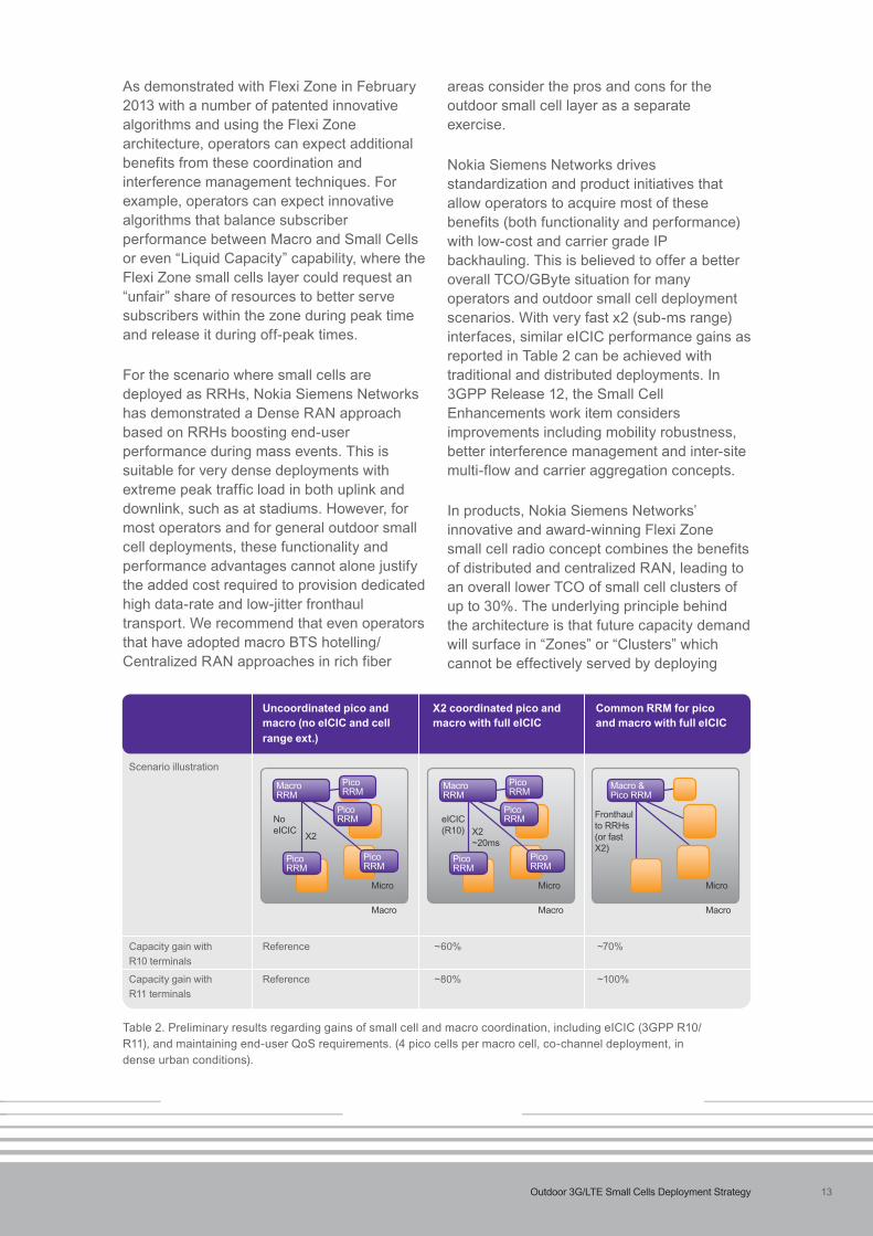
Some examples of performance results obtained with eICIC coordination alone are shown in Table 2, showing significant benefit from tight coordination between the macro and the small cell layers. A full integration step is possible with outdoor small cells by sharing (or pooling) baseband functions with macro cells and deploying the outdoor small cell RF as a low-power Remote Radio Head (RRH) with a dedicated fronthaul transport solution. This corresponds to a centralized baseband approach as seen from the small cell layer’s perspective and may be combined with a complete centralized RAN approach. In this case, the RRM functionality is shared between macro and small cells.
Many advantages exist, a particular one being the capability to perform inter-site carrier aggregation for higher peak rates and capacity performance between macro sites and small cell sites, allowing the macro carrier to provide robustness while the small cells deliver high capacity and peak rates. Other benefits when deployed in the same carrier include tightly coordinated scheduling gains, improvements to handover robustness and efficiency-boosting performance gains per small cell beyond the aforementioned eICIC gains – this can be up to 80-100% total gain over the non-eICIC case. The gain will depend on whether or not the user device can perform advanced interference cancellation (capability scheduled for 3GPP Release 11), as shown in the simulation results in Table 2. Current studies indicate that an RRH deployment offers only minor gains over what can be achieved with a very fast X2 (1-5 ms range) connection between macro and small cells.
13Outdoor 3G/LTE Small Cells Deployment Strategy
As demonstrated with Flexi Zone in February 2013 with a number of patented innovative algorithms and using the Flexi Zone architecture, operators can expect additional benefits from these coordination and interference management techniques. For example, operators can expect innovative algorithms that balance subscriber performance between Macro and Small Cells or even “Liquid Capacity” capability, where the Flexi Zone small cells layer could request an “unfair” share of resources to better serve subscribers within the zone during peak time and release it during off-peak times.
For the scenario where small cells are deployed as RRHs, Nokia Siemens Networks has demonstrated a Dense RAN approach based on RRHs boosting end-user performance during mass events. This is suitable for very dense deployments with extreme peak traffic load in both uplink and downlink, such as at stadiums. However, for most operators and for general outdoor small cell deployments, these functionality and performance advantages cannot alone justify the added cost required to provision dedicated high data-rate and low-jitter fronthaul transport. We recommend that even operators that have adopted macro BTS hotelling/Centralized RAN approaches in rich fiber
areas consider the pros and cons for the outdoor small cell layer as a separate exercise.
Nokia Siemens Networks drives standardization and product initiatives that allow operators to acquire most of these benefits (both functionality and performance) with low-cost and carrier grade IP backhauling. This is believed to offer a better overall TCO/GByte situation for many operators and outdoor small cell deployment scenarios. With very fast x2 (sub-ms range) interfaces, similar eICIC performance gains as reported in Table 2 can be achieved with traditional and distributed deployments. In 3GPP Release 12, the Small Cell Enhancements work item considers improvements including mobility robustness, better interference management and inter-site multi-flow and carrier aggregation concepts.
In products, Nokia Siemens Networks’ innovative and award-winning Flexi Zone small cell radio concept combines the benefits of distributed and centralized RAN, leading to an overall lower TCO of small cell clusters of up to 30%. The underlying principle behind the architecture is that future capacity demand will surface in “Zones” or “Clusters” which cannot be effectively served by deploying
Uncoordinated pico and X2 coordinated pico and Common RRM for pico macro (no eICIC and cell macro with full eICIC and macro with full eICIC range ext.) Scenario illustration
Capacity gain with Reference ~60% ~70% R10 terminals
Capacity gain with Reference ~80% ~100% R11 terminals
Macro
Micro
X2
No eICIC
MacroRRM
PicoRRM
PicoRRM
PicoRRM
PicoRRM
Macro
Micro
X2~20ms
eICIC(R10)
MacroRRM
PicoRRM
PicoRRM
PicoRRM
PicoRRM
Macro
Micro
Fronthaul to RRHs(or fast X2)
Macro & Pico RRM
Macro
Micro
X2
No eICIC
MacroRRM
PicoRRM
PicoRRM
PicoRRM
PicoRRM
Macro
Micro
X2~20ms
eICIC(R10)
MacroRRM
PicoRRM
PicoRRM
PicoRRM
PicoRRM
Macro
Micro
Fronthaul to RRHs(or fast X2)
Macro & Pico RRM
Macro
Micro
X2
No eICIC
MacroRRM
PicoRRM
PicoRRM
PicoRRM
PicoRRM
Macro
Micro
X2~20ms
eICIC(R10)
MacroRRM
PicoRRM
PicoRRM
PicoRRM
PicoRRM
Macro
Micro
Fronthaul to RRHs(or fast X2)
Macro & Pico RRM
Table 2. Preliminary results regarding gains of small cell and macro coordination, including eICIC (3GPP R10/R11), and maintaining end-user QoS requirements. (4 pico cells per macro cell, co-channel deployment, in dense urban conditions).
14 Outdoor 3G/LTE Small Cells Deployment Strategy
Small cell transport is a key area to address to ensure a viable small cell deployment. All operators and vendors agree that mass deployment of small cells will be influenced by the availability of cost-effective backhaul solutions. Nokia Siemens Networks estimates that the typical maximum cost indicator for stand-alone outdoor small cell transport should be <€2-3,000 per site (TCO over 5 years). Given such required cost indicators, traditional macro backhaul solutions do not readily meet the needs of outdoor small cell deployments. However, with new options and markets emerging in both owned/leased fiber and wireless domains, such cost levels will gradually become feasible for operators. There is no single transport technology, wireless or wired, that fits all deployment needs and cost constraints. The transport solution has to be considered an integral part of each outdoor small cell site’s overall proposition.
While debate continues on the best small cell backhaul and fronthaul transport options, Nokia Siemens Networks believes that small cells will require several flexible transport
7. Efficient Transport Solutions for Outdoor Small Cells
options for very diverse deployment scenarios, given that the usability, availability and cost of each option may vary by country, operator and area. As one example, the suitability of wired and wireless backhaul in a given country will depend significantly on both technology and market evolution and operators are strongly recommended to carefully and continually exploit their options in both spaces.
The transport solution requirements for each small cell deployment should be considered separately. For example, backhaul reliability requirements may be down-scaled provided that the overlay macro can fulfill emergency service requirements and baseline capacity. Form factor, on the other hand, may be a stricter requirement in order to be able to access attractive assets such as lamps, poles, shop walls, etc and backhaul in some cases may even need to be integrated in the small cell to provide a one box solution.
Given that outdoor small cells are deployed where there is high traffic demand and that user-experience needs to be similar to that of
traditional small cells which are designed for “Hot-Spots”. Flexi Zone distributes the base station architecture across two types of node, distributed APs and a centralized controller, the latter being located in a convenient, centralized location, aggregating the APs. The solution is scalable so that APs can initially be deployed as all-in-one pico cells and later upgraded by software to participate in a cluster.
Once a cluster is deployed, the operator can further “densify” its cluster with new APs when
extra capacity is required, as all APs appear to the rest of the network as a single entity. The concept addresses many of the topics discussed in this paper, including ease of deployment with low-cost transport, enhanced capacity and end-user experience via centralized functions, ease of integration to the wide area network and support for enhanced IP services and offload mechanisms suitable for local area deployments. This leads to overall reduced TCO compared to stand-alone small cell deployments.

15Outdoor 3G/LTE Small Cells Deployment Strategy
wide area, it is expected that requirements for transport speed and latency will remain similar to that of a macro cell. Transport capacity should be dimensioned according to peak service rates provided to users, to ensure that the TCO/value relationship is maintained for the small cell solution. This cannot benefit from statistical under-dimensioning as well as that achievable for a large macro site.
An important decision criterion for the mobile operator is the choice of whether to lease backhaul transport infrastructure or build its own. In particular, backhaul over the last mile can turn out to be a serious challenge for operators, as the target TCO level only allows a (leasing) budget in the order of €50 per month. Synchronization requirements of small cells have to be considered as part of the overall transport solution decision. When using advanced schemes such as eICIC and future TDD bands, additional requirements must be considered, and achieving time synchronization/alignment will incur a premium compared to cases which require frequency-only synchronization.
When deploying small cells as low-powered RRHs, the available functionality and performance improvements will support a somewhat higher transport TCO, but likely not to the point where very different transport technologies can be accepted compared to those used in outdoor small cell backhauling. It is believed that the primary choice for fronthaul to outdoor small cells will be to use a dedicated fiber solution towards an aggregation point comprising baseband equipment. Therefore, RRH implementation of small cells is expected to be limited to fiber-rich areas, but even then, fiber rarely goes to all light poles, walls and street furniture where small cells will be mounted, so some costly digging will be required. It is noted that due to tight latency, jitter and rate requirements, the cost indicators for fiber fronthaul can be several orders of magnitude higher than the €2-3,000 5-year TCO target for fiber backhaul, even in urban areas with a rich fiber infrastructure.
7.1 Wired transportWhen exploring options for wired transport solutions, it is important to recall the typical deployment scenario for outdoor small cells, i.e. densely populated urban areas. In these areas, the conditions for wired backhauling are progressively improving as fiber to the “x” (FTTx) becomes available. In particular, municipalities benefitting from national (funded) broadband initiatives can offer innovative business propositions, attacking incumbent lease line service providers on pricing for the last mile and using their local assets to offer bundled solutions beyond mere connectivity services. While focusing on fiber in the following, we recommend that operators additionally consider using other wired options in the small cell area that may be more accessible in the short- to mid-term. One such example is Hybrid Fiber-Coaxial (HFC) installations, which can support suitable speeds and which are common in areas with high cable TV penetration. A conceptual diagram of connecting small cell sites to a fiber infrastructure is shown in Figure 5.
Figure 5. Small cell sites connected to FTTx network.

16 Outdoor 3G/LTE Small Cells Deployment Strategy
Assuming that a fiber network is available, an operator has different choices depending on whether a fiber access network is owned, or alternatively whether fiber services can be leased from a third party provider. The total CapEx required for fiber is fairly negligible for an outdoor small cell site, even when some proportional spending on passive components in the fiber graph is needed. The real challenge is to get the small cell connected to the fiber network. The final fiber run to, for example, a pole, can be very costly due to labor intensive work, especially when it comes with street disruptions. For instance, it may be very relevant on which side of a street a small cell is being deployed, which means that transport decisions have to be conducted in combination with other considerations for optimizing site assets and costs.
Table 3 outlines five different fiber deployment models, sorted according to their attractiveness from a TCO perspective. Option 1 is the leanest option, where a site switch is already attached to an access fiber backbone and can be re-used. Very short reach and low-cost optical interfaces can be used and, even when a capacity upgrade of the
backbone link is needed to support the additional small cell traffic, CapEx figures are within an attractive range. In option 2, the new small cell is attached to an FTTx network which is owned and managed directly by the operator, usually in combination with fixed residential services. Connecting new small cells close to the fiber network’s access points generally results in low fiber ImpEx and CapEx. Actual non-recurring and recurring cost levels depend on the usage model (dark fiber or share lit fiber) as well as the operator’s internal accounting policies, but can be expected to be in the lower range.
The subsequent options apply to mobile operators without directly owned fiber access infrastructure, but within an area where FTTx services from third party providers are available. In this context, more and more bundled offerings are becoming available from local municipalities or utility providers with attractive leasing conditions. Such offerings include not only fiber connectivity, but also power supply and permission to deploy small cell equipment, for example, on street furniture. The backhauling models range from leasing dark fiber (option 3) to managed fiber
Table 3. Different FTTx scenarios and their TCO indicators* (0=lowest, 6=highest) for outdoor small cell transport in dense urban scenarios. (Options 1-4 will under favorable conditions fit within the expected target TCO level of 3k€ over 5 years.)
Fiber backhaul TCO Indicator* Deployment Deployment Small Cell Technology CapEx/ImpEx OpEx scenario conditions connection 1 Intra-site Site switch is Re-use of site Ethernet 1 0 cabling FTTx connected or building ducts, or CAT7, VSR cabling infra multi-mode
2 UseownFTTx Usedarkfiber, Ownaccessinfra, Agnostic,xPON, 2-3 1 sharelitfiber reuseaccessinfra CWDM
3 Leased dark From 3rd party Build own Agnostic 3 2 fiber provider,usuallyas accessinfra bundled contracts for e.g. district
4 Leased From 3rd party Leased of EFM, xPON 2 2-3 managedfiber provider,usuallyas accessinfra bundled contracts for with basic e2e e.g. district O&M
5 Leased line 3rd party leased Leased line service 100M, 1GbE, 1 3-5 service contract with SLA nx2/nx155M
6 Build own Deploy FTTx infra New FTTx rollout Agnostic 6 2 FTTx network build own access infra
17Outdoor 3G/LTE Small Cells Deployment Strategy
(option 4), or more expensive leased line services (option 5). Following discussions with different suppliers in dense urban areas, Nokia Siemens Networks has found that for some regions and countries, there is a growing availability of options 3 and 4 fitting to the TCO frame for small cell transport. Option 5 may in special cases be acceptable, while option 6, roll-out of new fiber, is not attractive.
Fiber connectivity is superior in terms of scalability, as fiber capacity upgrades are cheap and in terms of OpEx, for example passive optical networks. For outdoor small cells with wired transport, we expect the same fast shift towards fiber as has been seen with macro cells. Due to their “almost unlimited” transmission capacity, fiber solutions also allow sharing of the FTTx access infrastructure, which can drive down overall backhauling TCO still further. Assuming that an operator has long-term investment plans associated with outdoor small cell sites, the associated costs can be depreciated over a longer time (10-12 years typically, 20 years in some viewpoints) thus offering an attractively low OpEx.
7.2 Wireless transportAs discussed earlier, wired backhaul cannot always be an option if good fiber access conditions are not present in the small cell deployment area. For such cases, wireless transport is the only solution for deployment of outdoor small cells. Additionally, even in cases where both transport options may be viable, wireless backhaul may be preferable due to its higher flexibility for small cell installations and elimination of time-consuming construction, digging or planning work. Even a change of the site location will not lead to big changes in costs for relocation of wireless hops. Wireless technologies are nowadays under constant development and innovations are constantly
being introduced that will help to bring 5-year TCO levels down to and eventually below the €2-3,000 requirement. However, the low absolute TCO requirements will prevent many macro-suitable wireless transport options from becoming successful in the small cell landscape. Nokia Siemens Networks expects that hybrid architectures will also emerge, for example, clusters with mixed transport options between elements.
For small cell sites below rooftop level, LOS approaches will become challenging, especially as small cells become densely deployed and given a high presence of dynamic obstacles such as trucks, vegetation, etc. Nokia Siemens Networks expects new transport topologies to emerge to support deployment of outdoor small cells. In many cases, near LOS (nLOS) or non-LOS (NLOS) wireless backhaul solutions below 7 GHz will be required. Such technologies may be deployed as point to point (P2P) wireless interworking from, for example, pole to pole (referred to as Street Haul). Alternatively, small cell connectivity may be provided to a street cluster from a high roof top site (referred to as Street-Egress) as either P2P or point to multi-point (P2MP).
Street Egress deployments may be suitable for higher frequency LOS transport technologies. In addition, mesh topologies can be used to provide path protection and as a way to circumvent obstacles for LOS wireless technologies, essentially providing a NLOS path even where there is no LOS from end-to-end. Mesh systems are not yet common in transport, but they constitute one promising future small-cell technique in particular associated with mmW (millimeter waves) spectrum and technology. A typical break-down of wireless transport technologies is considered in Table 4. Frequency licenses are typically granted for a hop or for a certain geographical area.

18 Outdoor 3G/LTE Small Cells Deployment Strategy
The operation of wireless backhaul below 7 GHz presents its own set of challenges. Licensed operation at below 7GHz can be restricted by spectrum availability, as the same frequencies can be used for mobile access, so balancing between access and backhaul is a key issue. To get sufficient performance, the technology solution must
provide a high bitrate/Hz and will typically require designs supporting directional adjustability, beam-forming, high modulation and interference mitigation. Most operators deploying outdoor small cells before 2016 are likely to do so due to capacity needs and spectrum shortage, and so using licensed LTE spectrum is challenging. LTE relaying
Frequency Type Typical Max Considerations for Outdoor Small Cells Capcity MWR < 7 GHz P2P, P2MP, Mesh, 200 Mbps, maybe Licensed band (WIMAX, LTE) is expensive and limited,
LOS, nLOS, NLOS extended with more calling for a balance between access and backhaul. spectrum in 3GPP Solutions need design for directionality (e.g. beam-forming), high modulation and interference mitigation to get to a suitable target of 3-4 bits/Hz to support small cell access and street topologies. Unlicensed band provides very low cost. QoS is harder to control due to interference from e.g. Wi-Fi, Wireless ISPs, wireless Ethernet bridges. Some availability challenges due to regulatory issues (e.g. radar detection). Cost indicators: can be feasible for outdoor small cells but opportunity cost of spectrum (licensed) and QoS issues (unlicensed) need to be carefully considered.
MWR 6-50 GHz P2P, P2MP, LOS 1-2 Gbps Licensed LOS, some bands are congested in urban areas and adoption of new bands not global. Only higher microwave bands offer attractive form factors for small cells. Cost indicators: can be acceptable but generally the solutions using the highest microwave bands and with less advanced feature sets appear plausible for outdoor small cells.
mmWave P2P, LOS Multi-Gbps Street acceptable antenna size, tight beam-width requirements 57-66 GHz (3 degrees) to be considered related to e.g. pole sway and twist. Unlicensed band. Cost indicators: are on the high side today but expected to evolve closer towards a feasible range for outdoor small cells.
E-Band P2P, LOS Multi-Gbps Same as 60 GHz but is lightly-licensed. 71-95 GHz Cost indicators: are on the high side today but expected to evolve closer towards a feasible range for outdoor small cells.
Very directional making it not suitable today – for street level would need mean to beam steer to stay in focus and compensate for pole sway/vibrations.
Free Space P2P, LOS 2.5 Gbps Unlicensed but needs very strict antenna alignment, high Optics sensitivity to environmental factors (like pole sway). Cost indicators: are not expected to become feasible for outdoor small cells in the next 5 years
Satellite P2MP, LOS <1 Gbps Expensive solution, only for selected dispersed small cell deployments in rural areas. Shared capacity means low suitability for outdoor small cell capacity sites. Cost indicators: not generally feasible for outdoor small cells, and link speeds limited to <100 Mbp
Table 4. Wireless transport types and their key characteristics in relation to outdoor small cells.

19Outdoor 3G/LTE Small Cells Deployment Strategy
techniques have been studied to find a more dynamic tradeoff between access and transport resource allocation. In general however, it is found that in-band relaying provides limited benefits over dedicating spectrum for transport for capacity sites. For low-capacity sites with very difficult transport access or cost factors, relaying (or even dedicated LTE backhauling) may however offer a convenient solution for the operator.
The use of unlicensed spectrum below 7 GHz provides both low cost and relatively wide spectrum bandwidth but is crowded and highly changeable given the presence of various fixed and mobile devices. Strict regulations on operations, such as radar detection and dynamic frequency selection (DFS), requires the ceasing of usage of a particular channel for a prolonged time, for example 30 minutes, when a radar signal is detected. These concerns have caused many operators to avoid the use of the spectrum. However, a continued desire for wireless backhaul and spectrum is forcing operators to reconsider using unlicensed spectrum. Nokia Siemens Networks has been assessing operational aspects related to backhaul performance in unlicensed spectrum and currently sees unlicensed spectrum at 5 GHz as viable, but that it must be operated within a set of constraints and limitations which
Figure 6. Indicative and relative cost indicators for current and expected wireless backhaul types, seen in an outdoor small cell context. (CapEx relates to equipment cost. ImpEx relates to installation and planning. OpEx includes maintenance, transport energy, and spectrum licensing costs. Note that the performance of the different schemes is not identical.)
Nokia Siemens Networks feels are quite manageable for outdoor small cells
Nokia Siemens Networks believes that solutions beyond 60 GHz offer attractive prospects for outdoor small cells, with both promising cost indicators and form factors. When using these frequencies together with advanced antenna technologies like electrically-steerable, very narrow beams, it is possible to achieve “no touch” installation and automatic re-alignment, maximizing backhaul performance and enabling low installation cost. These technologies, combined with directional mesh concepts, will enable high-capacity and low-cost, holistic, self-organized backhaul in the future and represent a key topic in Nokia Siemens Networks’ research portfolio as shown in February 2013 as part of the Flexi Zone demonstration.
In terms of TCO, wireless solutions have different challenges compared to wired transport, where establishing the physical connection is the key aspect. Among key requirements to enable low-cost backhaul installations are features supporting zero-touch installation, that is, minimizing human intervention. Additionally, any site required for wireless transmission needs to be carefully considered. With wireless backhaul, multiple sites may be needed for each outdoor small
2.5
2
1.5
1
0.5
0NLOS P2P
(2012)LOS P2P
(2012)LOS P2MP
(2012)NLOS LTE
(2015)NLOS
WIMAX(2015)
NLOS WIFI(2015)
LOS(2015)
CapEx
ImpEx
OpEx (5 years)

20 Outdoor 3G/LTE Small Cells Deployment Strategy
Throughout this paper we have taken care to stress that all factors related to the selection and deployment of an outdoor small cell site need to be considered with a fully holistic mindset. Small cells cannot simply be considered as low-powered macro cells or else the business case for outdoor small cells will be challenged, despite the fact they will be essential for operators to support future traffic growth. In effect, outdoor small cells bring many unique factors which strongly influence the selection of an appropriate small cell solution for a specific location, including what types of small cell will best meet the planned and anticipated service coverage, what options and implications exist for physical deployment and what the possibilities are for good performance, low cost transport.
An important factor is to establish the value of an outdoor small cell (or small cell cluster), that is, ensuring that a sufficiently high number of end-users served by the small cell site will depend on the provided service, thus justifying the investment – this is done by getting a clear and precise understanding of where the operator’s traffic is, requiring a new set of tools for hotspot/hotzone identification and planning.
Transport is a key part of the outdoor small cell solution. The most feasible transport options need to be assessed on a case-by-
8. Conclusion
case basis, with consideration given to local usability, availability and cost factors. The optimal solution may be fiber-, copper- or wireless-based, or a hybrid of these. We have discussed within this paper new enablers for lower transport costs, which will help make outdoor small cells an attractive deployment option.
As also discussed within this paper, choices within different cost areas closely interact, resulting in an almost unique mix of requirements for each small cell site. Consequently, for deployment of outdoor small cells, solutions are needed rather than boxes. A good solution integrates all processes, from planning, installation, effective technology and smart site solutions and optimization, among others. Nokia Siemens Networks takes a holistic approach to small cells over the complete life-cycle of the solution. This goes beyond product specification and features, and includes professional services and the establishment of key partners to reduce the TCO for small cells. Nokia Siemens Networks’ leadership within macro networks, innovative small cell solutions such as Flexi Zone and a life-cycle focus, including our unique Services for HetNet, positions us as the leading strategic partner for operatorsmoving towards the new paradigm of Heterogeneous Networks.
cell site in order to reach the first common transport hub or, if available, the high capacity backhaul of the nearest macro site. Thus cost aspects need to be carefully considered and thus planned together as part of the overall radio solution, also taking into account the density of the small cells. To enable the right flexibility for operators to reduce their costs, a wireless backhaul solution must support various wireless backhaul topologies, such as P2P, P2MP
and daisy-chaining or mesh. Combined radio and transport solutions may further offer increased deployment flexibility and improved performance. One example is the delay tolerant Flexi Zone architecture that allows for delay variance in mobile backhaul, enabling the use of lower cost transport using low-cost NLOS technologies. An indicative comparison of different wireless transport solutions applicable for outdoor small cells is shown in Figure 6.

21Outdoor 3G/LTE Small Cells Deployment Strategy
AAS Active antenna systemAP Access pointCapEx Capital expenditureCO2 Carbon dioxideCoMP Coordinated multipointeICIC Enhanced inter-cell interference coordinationFCAPS Fault management, configuration,
accounting, performance, & security
FTTx Fiber to the “x” GaN Gallium NitrideHD High-definitionHFC Hybrid fiber-coaxial HSPA High speed packet accessImpEx Implementation expensesLOS Line of sight LTE Long term evolutionMORAN Multi-operator radio access
network
MOCN Multi-operator core network MIMO Multiple input multiple outputMLB Mobility load balancing MRO Mobility robustness optimizationnLOS Near LOSNLOS Non-LOS O&M Operations &maintenanceOpEx Operating expensesP2MP Point to multi-point P2P Point to point QoS Quality of ServiceRF Radio frontendRAN Radio Access Network RRH Remote Radio HeadRRM Radio resource managementSoC System on chipSON Self Organizing NetworkTCO Total cost of ownershipTDD Time Division Duplex
9. Abbreviations

22 Outdoor 3G/LTE Small Cells Deployment Strategywww.nokiasiemensnetworks.com
Nokia Siemens NetworksP.O. Box 1FI-02022 NOKIA SIEMENS NETWORKSFinlandVisiting address:Karaportti 3, ESPOO, Finland
Switchboard +358 71 400 4000 (Finland)Switchboard +49 89 5159 01 (Germany)
Copyright © 2013 Nokia Siemens Networks.All rights reserved.
Nokia is a registered trademark of Nokia Corporation,Siemens is a registered trademark of Siemens AG.The wave logo is a trademark of Nokia Siemens Networks Oy.Other company and product names mentioned in thisdocument may be trademarks of their respective owners,andtheyarementionedforidentificationpurposesonly.
This publication is issued to provide information only and isnot to form part of any order or contract. The products andservices described herein are subject to availability andchange without notice.