Embed Size (px)
Citation preview
Bus Interface
ISA Bus
Peripheral Component Interconnect (PCI) Bus
Parallel Printer Interface
Serial COM Parts
Universal Serial Bus
1 __________________________ ____________________________ ____________________________ ____________________________ ____________________________ ____________________________ ____________________________ ____________________________ ____________________________
*Property of STI I0022
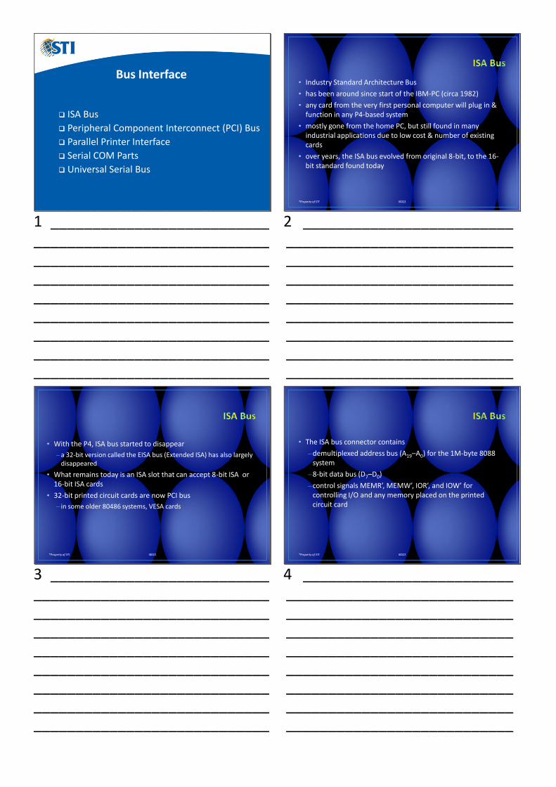
• Industry Standard Architecture Bus
• has been around since start of the IBM-PC (circa 1982)
• any card from the very first personal computer will plug in & function in any P4-based system
• mostly gone from the home PC, but still found in many industrial applications due to low cost & number of existing cards
• over years, the ISA bus evolved from original 8-bit, to the 16-bit standard found today
2 _________________________ ___________________________ ___________________________ ___________________________ ___________________________ ___________________________ ___________________________ ___________________________ ___________________________
*Property of STI I0022
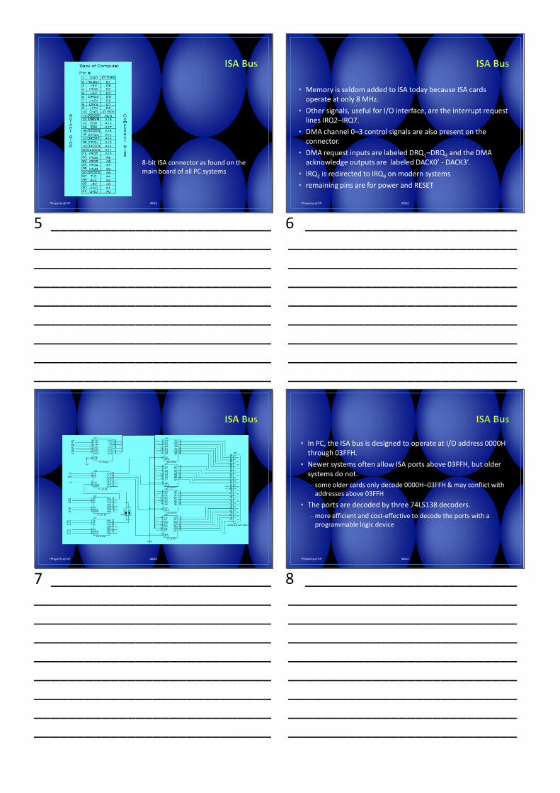
• With the P4, ISA bus started to disappear
– a 32-bit version called the EISA bus (Extended ISA) has also largely disappeared
• What remains today is an ISA slot that can accept 8-bit ISA or 16-bit ISA cards
• 32-bit printed circuit cards are now PCI bus
– in some older 80486 systems, VESA cards
3 __________________________ ____________________________ ____________________________ ____________________________ ____________________________ ____________________________ ____________________________ ____________________________ ____________________________
*Property of STI I0022
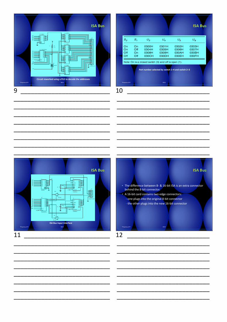
• The ISA bus connector contains
–demultiplexed address bus (A19–A0) for the 1M-byte 8088 system
–8-bit data bus (D7–D0)
–control signals MEMR’, MEMW’, IOR’, and IOW’ for controlling I/O and any memory placed on the printed circuit card
4 _________________________ ___________________________ ___________________________ ___________________________ ___________________________ ___________________________ ___________________________ ___________________________ ___________________________
*Property of STI I0022
8-bit ISA connector as found on the main board of all PC systems
5 __________________________ ____________________________ ____________________________ ____________________________ ____________________________ ____________________________ ____________________________ ____________________________ ____________________________
*Property of STI I0022
• Memory is seldom added to ISA today because ISA cards operate at only 8 MHz.
• Other signals, useful for I/O interface, are the interrupt request lines IRQ2–IRQ7.
• DMA channel 0–3 control signals are also present on the connector.
• DMA request inputs are labeled DRQ1–DRQ3 and the DMA acknowledge outputs are labeled DACK0’ - DACK3’.
• IRQ2 is redirected to IRQ9 on modern systems
• remaining pins are for power and RESET
6 _________________________ ___________________________ ___________________________ ___________________________ ___________________________ ___________________________ ___________________________ ___________________________ ___________________________
*Property of STI I0022
7 __________________________ ____________________________ ____________________________ ____________________________ ____________________________ ____________________________ ____________________________ ____________________________ ____________________________
*Property of STI I0022
• In PC, the ISA bus is designed to operate at I/O address 0000H through 03FFH.
• Newer systems often allow ISA ports above 03FFH, but older systems do not.
– some older cards only decode 0000H–03FFH & may conflict with addresses above 03FFH
• The ports are decoded by three 74LS138 decoders.
–more efficient and cost-effective to decode the ports with a programmable logic device
8 _________________________ ___________________________ ___________________________ ___________________________ ___________________________ ___________________________ ___________________________ ___________________________ ___________________________
*Property of STI I0022
Circuit reworked using a PLD to decode the addresses
9 __________________________ ____________________________ ____________________________ ____________________________ ____________________________ ____________________________ ____________________________ ____________________________ ____________________________
*Property of STI I0022
Port number selected by switch 1–4 and switch 2–3
10 ________________________ ___________________________ ___________________________ ___________________________ ___________________________ ___________________________ ___________________________ ___________________________ ___________________________
*Property of STI I0022
ISA Bus Input Interface
11 _________________________ ____________________________ ____________________________ ____________________________ ____________________________ ____________________________ ____________________________ ____________________________ ____________________________
*Property of STI I0022
• The difference between 8- & 16-bit ISA is an extra connector behind the 8-bit connector.
• A 16-bit card contains two edge connectors:
–one plugs into the original 8-bit connector
–the other plugs into the new 16-bit connector
12 ________________________ ___________________________ ___________________________ ___________________________ ___________________________ ___________________________ ___________________________ ___________________________ ___________________________
*Property of STI I0022
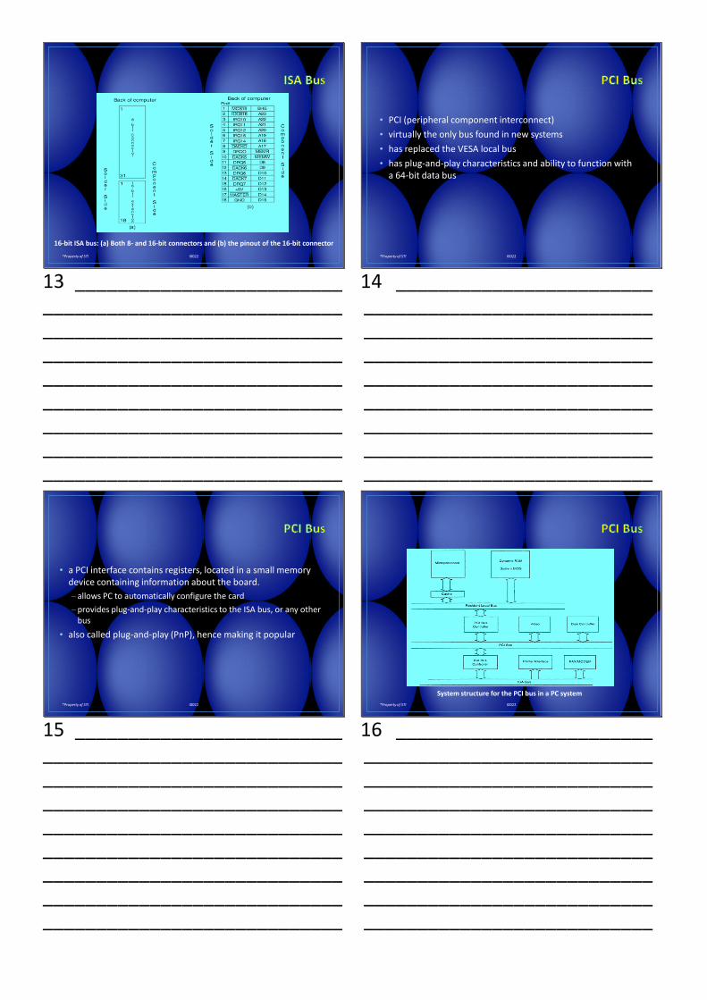
16-bit ISA bus: (a) Both 8- and 16-bit connectors and (b) the pinout of the 16-bit connector
13 _________________________ ____________________________ ____________________________ ____________________________ ____________________________ ____________________________ ____________________________ ____________________________ ____________________________
*Property of STI I0022
• PCI (peripheral component interconnect)
• virtually the only bus found in new systems
• has replaced the VESA local bus
• has plug-and-play characteristics and ability to function with a 64-bit data bus
14 ________________________ ___________________________ ___________________________ ___________________________ ___________________________ ___________________________ ___________________________ ___________________________ ___________________________
*Property of STI I0022
• a PCI interface contains registers, located in a small memory device containing information about the board.
– allows PC to automatically configure the card
–provides plug-and-play characteristics to the ISA bus, or any other bus
• also called plug-and-play (PnP), hence making it popular
15 _________________________ ____________________________ ____________________________ ____________________________ ____________________________ ____________________________ ____________________________ ____________________________ ____________________________
*Property of STI I0022
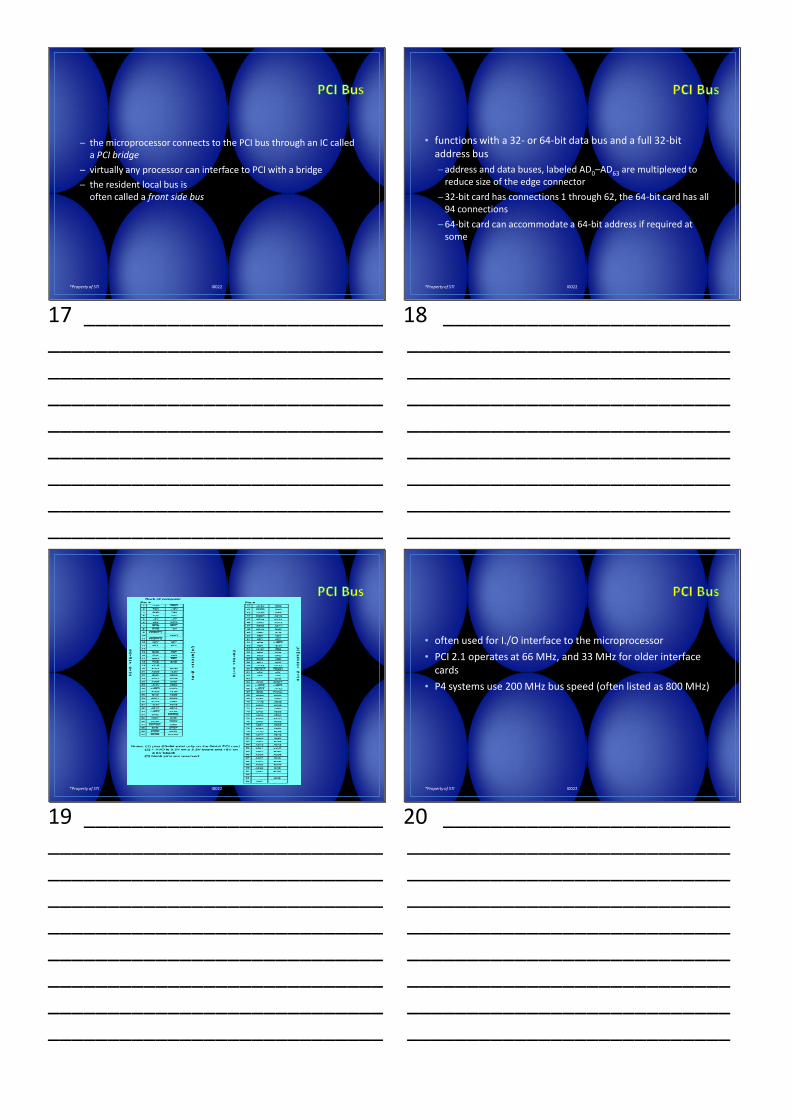
System structure for the PCI bus in a PC system
16 ________________________ ___________________________ ___________________________ ___________________________ ___________________________ ___________________________ ___________________________ ___________________________ ___________________________
*Property of STI I0022
─ the microprocessor connects to the PCI bus through an IC called a PCI bridge
─ virtually any processor can interface to PCI with a bridge
─ the resident local bus isoften called a front side bus
17 _________________________ ____________________________ ____________________________ ____________________________ ____________________________ ____________________________ ____________________________ ____________________________ ____________________________
*Property of STI I0022
• functions with a 32- or 64-bit data bus and a full 32-bit address bus
─ address and data buses, labeled AD0–AD63 are multiplexed to reduce size of the edge connector
─ 32-bit card has connections 1 through 62, the 64-bit card has all 94 connections
─ 64-bit card can accommodate a 64-bit address if required at some
18 ________________________ ___________________________ ___________________________ ___________________________ ___________________________ ___________________________ ___________________________ ___________________________ ___________________________
*Property of STI I0022
19 _________________________ ____________________________ ____________________________ ____________________________ ____________________________ ____________________________ ____________________________ ____________________________ ____________________________
*Property of STI I0022
• often used for I./O interface to the microprocessor
• PCI 2.1 operates at 66 MHz, and 33 MHz for older interface cards
• P4 systems use 200 MHz bus speed (often listed as 800 MHz)
20 ________________________ ___________________________ ___________________________ ___________________________ ___________________________ ___________________________ ___________________________ ___________________________ ___________________________
*Property of STI I0022
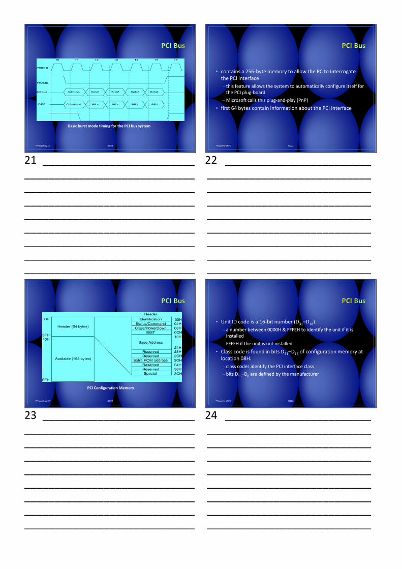
Basic burst mode timing for the PCI bus system
21 _________________________ ____________________________ ____________________________ ____________________________ ____________________________ ____________________________ ____________________________ ____________________________ ____________________________
*Property of STI I0022
• contains a 256-byte memory to allow the PC to interrogate the PCI interface
– this feature allows the system to automatically configure itself for the PCI plug-board
–Microsoft calls this plug-and-play (PnP)
• first 64 bytes contain information about the PCI interface
22 ________________________ ___________________________ ___________________________ ___________________________ ___________________________ ___________________________ ___________________________ ___________________________ ___________________________
*Property of STI I0022
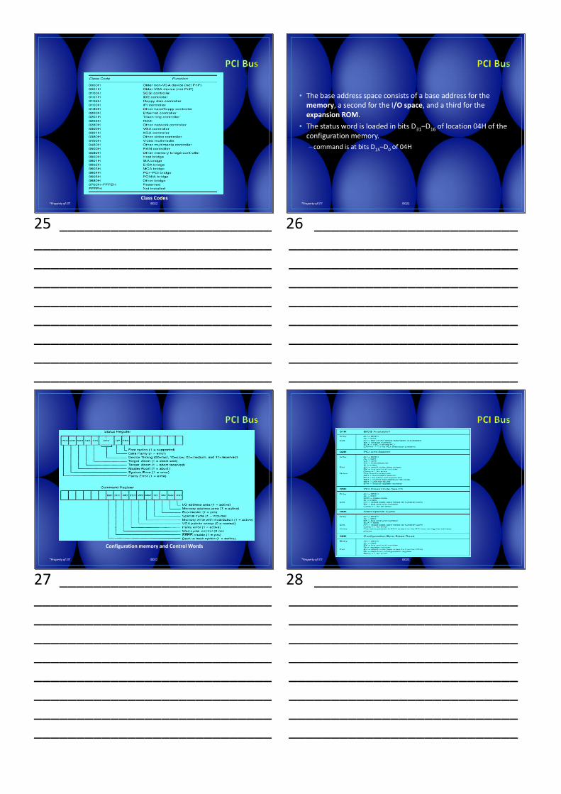
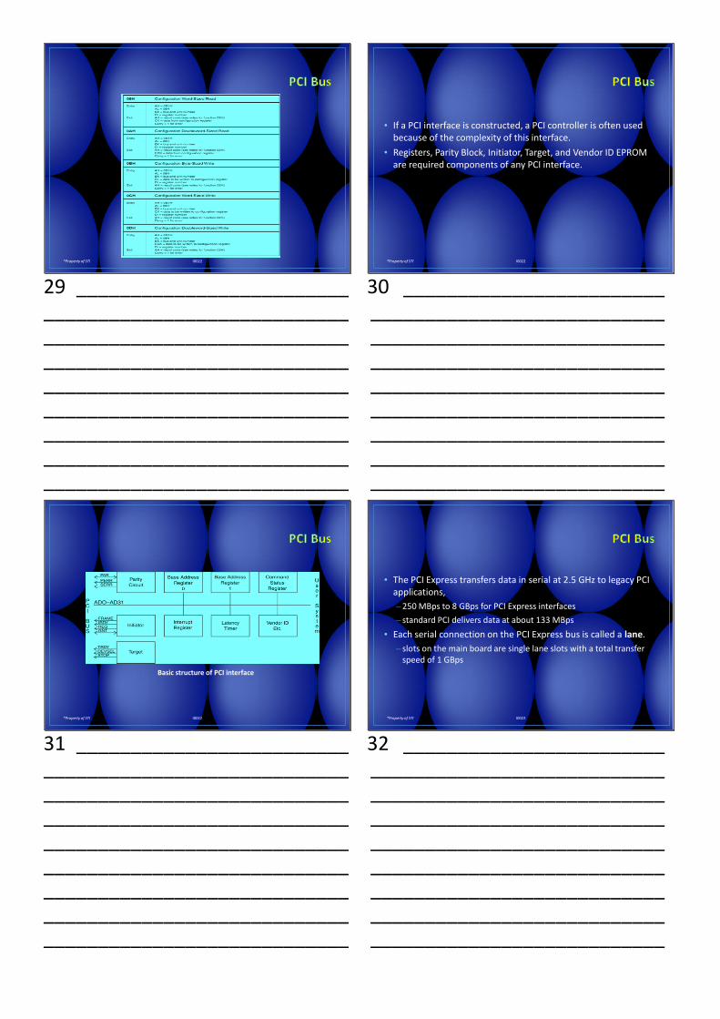
PCI Configuration Memory
23 _________________________ ____________________________ ____________________________ ____________________________ ____________________________ ____________________________ ____________________________ ____________________________ ____________________________
*Property of STI I0022
• Unit ID code is a 16-bit number (D31–D16).
– a number between 0000H & FFFEH to identify the unit if it is installed
– FFFFH if the unit is not installed
• Class code is found in bits D31–D16 of configuration memory at location 08H.
– class codes identify the PCI interface class
–bits D15–D0 are defined by the manufacturer
24 ________________________ ___________________________ ___________________________ ___________________________ ___________________________ ___________________________ ___________________________ ___________________________ ___________________________
*Property of STI I0022
Class Codes
25 _________________________ ____________________________ ____________________________ ____________________________ ____________________________ ____________________________ ____________________________ ____________________________ ____________________________
*Property of STI I0022
• The base address space consists of a base address for the memory, a second for the I/O space, and a third for the expansion ROM.
• The status word is loaded in bits D31–D16 of location 04H of the configuration memory.
– command is at bits D15–D0 of 04H
26 ________________________ ___________________________ ___________________________ ___________________________ ___________________________ ___________________________ ___________________________ ___________________________ ___________________________
*Property of STI I0022
Configuration memory and Control Words
27 _________________________ ____________________________ ____________________________ ____________________________ ____________________________ ____________________________ ____________________________ ____________________________ ____________________________
*Property of STI I0022
28 ________________________ ___________________________ ___________________________ ___________________________ ___________________________ ___________________________ ___________________________ ___________________________ ___________________________
*Property of STI I0022
29 _________________________ ____________________________ ____________________________ ____________________________ ____________________________ ____________________________ ____________________________ ____________________________ ____________________________
*Property of STI I0022
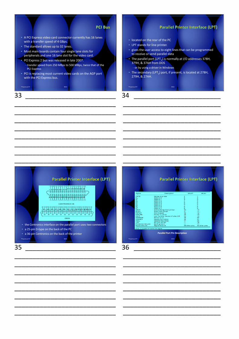
• If a PCI interface is constructed, a PCI controller is often used because of the complexity of this interface.
• Registers, Parity Block, Initiator, Target, and Vendor ID EPROM are required components of any PCI interface.
30 ________________________ ___________________________ ___________________________ ___________________________ ___________________________ ___________________________ ___________________________ ___________________________ ___________________________
*Property of STI I0022
Basic structure of PCI interface
31 _________________________ ____________________________ ____________________________ ____________________________ ____________________________ ____________________________ ____________________________ ____________________________ ____________________________
*Property of STI I0022
• The PCI Express transfers data in serial at 2.5 GHz to legacy PCI applications,
– 250 MBps to 8 GBps for PCI Express interfaces
– standard PCI delivers data at about 133 MBps
• Each serial connection on the PCI Express bus is called a lane.
– slots on the main board are single lane slots with a total transfer speed of 1 GBps
32 ________________________ ___________________________ ___________________________ ___________________________ ___________________________ ___________________________ ___________________________ ___________________________ ___________________________
*Property of STI I0022
• A PCI Express video card connector currently has 16 lanes with a transfer speed of 4 GBps.
• The standard allows up to 32 lanes.
• Most main boards contain four single lane slots for peripherals and one 16 lane slot for the video card.
• PCI Express 2 bus was released in late 2007.
– transfer speed from 250 MBps to 500 MBps, twice that of the PCI Express
• PCI is replacing most current video cards on the AGP port with the PCI Express bus.
33 _________________________ ____________________________ ____________________________ ____________________________ ____________________________ ____________________________ ____________________________ ____________________________ ____________________________
*Property of STI I0022
• located on the rear of the PC
• LPT stands for line printer.
• gives the user access to eight lines that can be programmed to receive or send parallel data
• The parallel port (LPT1) is normally at I/O addresses 378H, 379H, & 37AH from DOS
–or by using a driver in Windows
• The secondary (LPT2) port, if present, is located at 278H, 279H, & 27AH.
34 ________________________ ___________________________ ___________________________ ___________________________ ___________________________ ___________________________ ___________________________ ___________________________ ___________________________
*Property of STI I0022
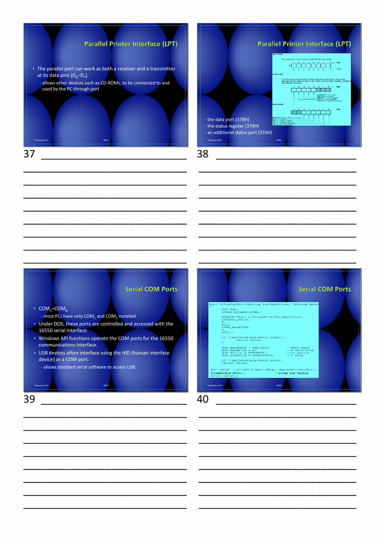
• the Centronics interface on the parallel port uses two connectors
• a 25-pin D-type on the back of the PC
• a 36-pin Centronics on the back of the printer
35 _________________________ ____________________________ ____________________________ ____________________________ ____________________________ ____________________________ ____________________________ ____________________________ ____________________________
*Property of STI I0022
Parallel Port Pin Description
36 ________________________ ___________________________ ___________________________ ___________________________ ___________________________ ___________________________ ___________________________ ___________________________ ___________________________
*Property of STI I0022
• The parallel port can work as both a receiver and a transmitter at its data pins (D0–D7).
– allows other devices such as CD-ROMs, to be connected to and used by the PC through port
37 _________________________ ____________________________ ____________________________ ____________________________ ____________________________ ____________________________ ____________________________ ____________________________ ____________________________
*Property of STI I0022
– the data port (378H)
– the status register (379H)
– an additional status port (37AH)
38 ________________________ ___________________________ ___________________________ ___________________________ ___________________________ ___________________________ ___________________________ ___________________________ ___________________________
*Property of STI I0022
• COM1–COM8
–most PCs have only COM1 and COM2 installed
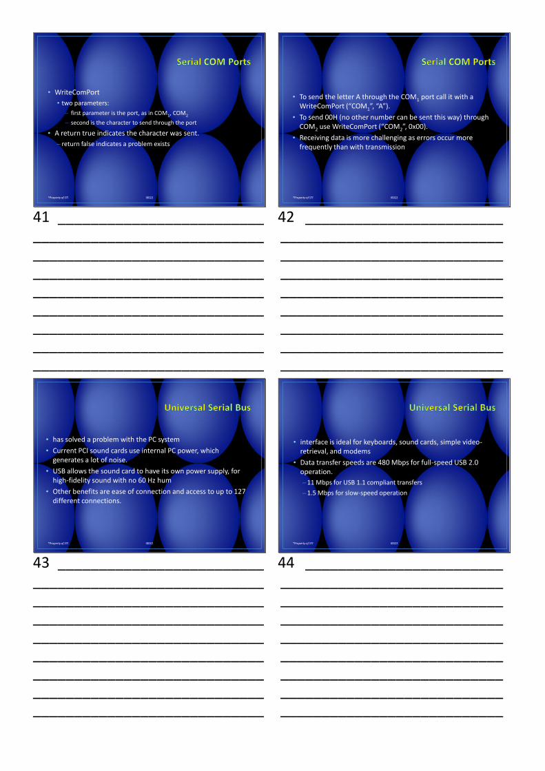
• Under DOS, these ports are controlled and accessed with the 16550 serial interface.
• Windows API functions operate the COM ports for the 16550 communications interface.
• USB devices often interface using the HID (human interface device) as a COM port.
– allows standard serial software to access USB
39 _________________________ ____________________________ ____________________________ ____________________________ ____________________________ ____________________________ ____________________________ ____________________________ ____________________________
*Property of STI I0022
40 ________________________ ___________________________ ___________________________ ___________________________ ___________________________ ___________________________ ___________________________ ___________________________ ___________________________
*Property of STI I0022
• WriteComPort
• two parameters:
– first parameter is the port, as in COM1, COM2
– second is the character to send through the port
• A return true indicates the character was sent.
– return false indicates a problem exists
41 _________________________ ____________________________ ____________________________ ____________________________ ____________________________ ____________________________ ____________________________ ____________________________ ____________________________
*Property of STI I0022
• To send the letter A through the COM1 port call it with a WriteComPort (“COM1”, “A”).
• To send 00H (no other number can be sent this way) through COM2 use WriteComPort (“COM2”, 0x00).
• Receiving data is more challenging as errors occur more frequently than with transmission
42 ________________________ ___________________________ ___________________________ ___________________________ ___________________________ ___________________________ ___________________________ ___________________________ ___________________________
*Property of STI I0022
• has solved a problem with the PC system
• Current PCI sound cards use internal PC power, which generates a lot of noise.
• USB allows the sound card to have its own power supply, for high-fidelity sound with no 60 Hz hum
• Other benefits are ease of connection and access to up to 127 different connections.
43 _________________________ ____________________________ ____________________________ ____________________________ ____________________________ ____________________________ ____________________________ ____________________________ ____________________________
*Property of STI I0022
• interface is ideal for keyboards, sound cards, simple video-retrieval, and modems
• Data transfer speeds are 480 Mbps for full-speed USB 2.0 operation.
– 11 Mbps for USB 1.1 compliant transfers
–1.5 Mbps for slow-speed operation
44 ________________________ ___________________________ ___________________________ ___________________________ ___________________________ ___________________________ ___________________________ ___________________________ ___________________________
*Property of STI I0022
• Cable lengths are limited to five meters for the full-speed interface and three meters maximum for the low-speed interface.
• Maximum power through the cables is rated at 100 mA, maximum current at 5.0 V.
– if current exceeds 100 mA, Windows will indicate an overload condition
45 _________________________ ____________________________ ____________________________ ____________________________ ____________________________ ____________________________ ____________________________ ____________________________ ____________________________
*Property of STI I0022
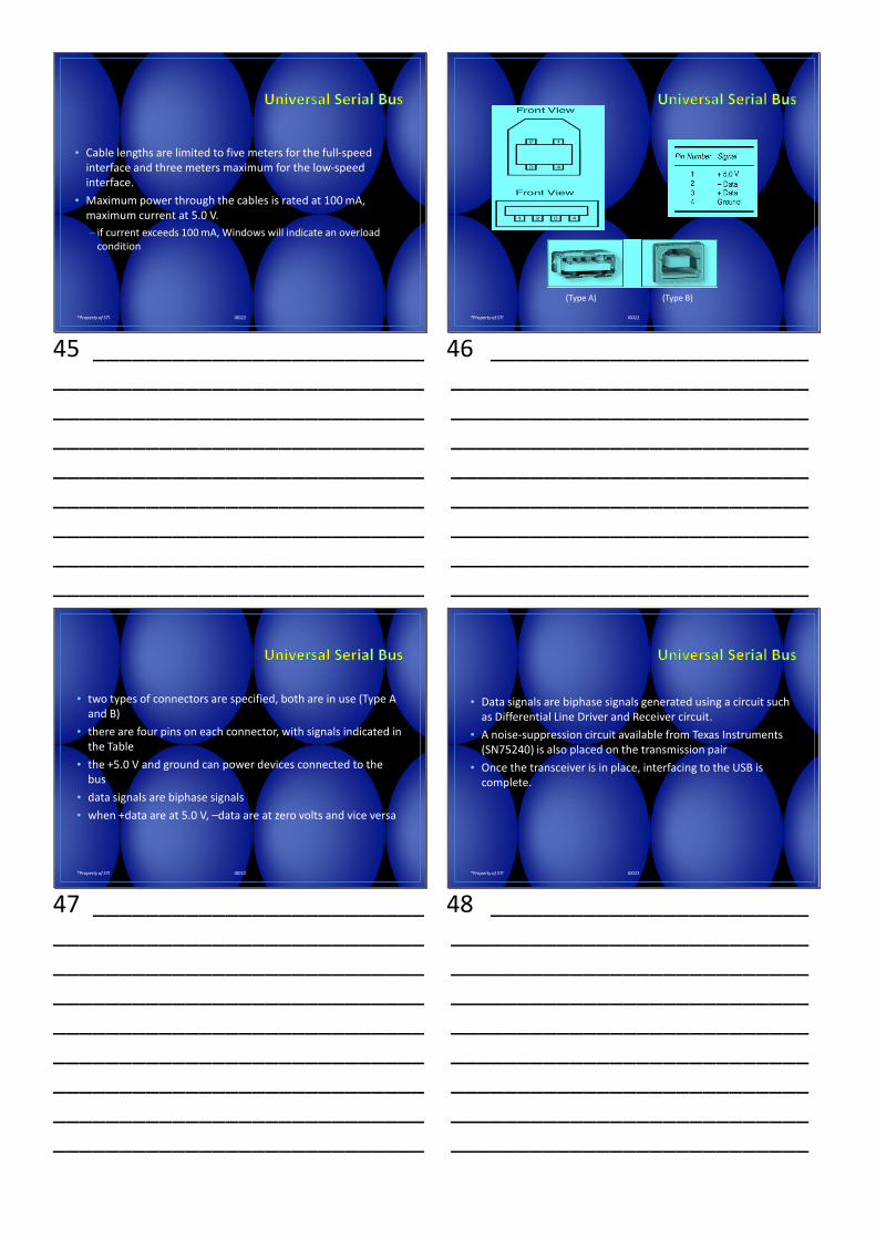
(Type A) (Type B)
46 ________________________ ___________________________ ___________________________ ___________________________ ___________________________ ___________________________ ___________________________ ___________________________ ___________________________
*Property of STI I0022
• two types of connectors are specified, both are in use (Type A and B)
• there are four pins on each connector, with signals indicated in the Table
• the +5.0 V and ground can power devices connected to the bus
• data signals are biphase signals
• when +data are at 5.0 V, –data are at zero volts and vice versa
47 _________________________ ____________________________ ____________________________ ____________________________ ____________________________ ____________________________ ____________________________ ____________________________ ____________________________
*Property of STI I0022
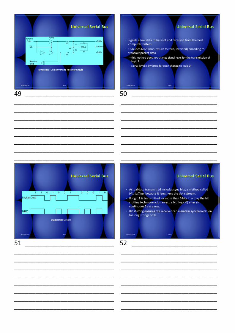
• Data signals are biphase signals generated using a circuit such as Differential Line Driver and Receiver circuit.
• A noise-suppression circuit available from Texas Instruments (SN75240) is also placed on the transmission pair
• Once the transceiver is in place, interfacing to the USB is complete.
48 ________________________ ___________________________ ___________________________ ___________________________ ___________________________ ___________________________ ___________________________ ___________________________ ___________________________
*Property of STI I0022
Differential Line Driver and Receiver Circuit
49 _________________________ ____________________________ ____________________________ ____________________________ ____________________________ ____________________________ ____________________________ ____________________________ ____________________________
*Property of STI I0022
• signals allow data to be sent and received from the host computer system
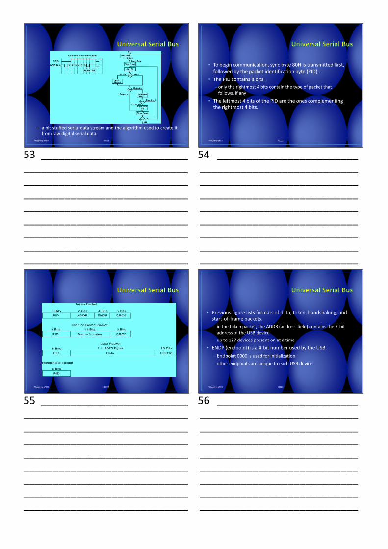
• USB uses NRZI (non-return to zero, inverted) encoding to transmit packet data
─ this method does not change signal level for the transmission of logic 1
─ signal level is inverted for each change to logic 0
50 ________________________ ___________________________ ___________________________ ___________________________ ___________________________ ___________________________ ___________________________ ___________________________ ___________________________
*Property of STI I0022
Digital Data Stream
51 _________________________ ____________________________ ____________________________ ____________________________ ____________________________ ____________________________ ____________________________ ____________________________ ____________________________
*Property of STI I0022
• Actual data transmitted includes sync bits, a method called bit stuffing, because it lengthens the data stream.
• If logic 1 is transmitted for more than 6 bits in a row, the bit stuffing technique adds an extra bit (logic 0) after six continuous 1s in a row.
• Bit stuffing ensures the receiver can maintain synchronization for long strings of 1s.
52 ________________________ ___________________________ ___________________________ ___________________________ ___________________________ ___________________________ ___________________________ ___________________________ ___________________________
*Property of STI I0022
– a bit-stuffed serial data stream and the algorithm used to create itfrom raw digital serial data
53 _________________________ ____________________________ ____________________________ ____________________________ ____________________________ ____________________________ ____________________________ ____________________________ ____________________________
*Property of STI I0022
• To begin communication, sync byte 80H is transmitted first, followed by the packet identification byte (PID).
• The PID contains 8 bits.
–only the rightmost 4 bits contain the type of packet that follows, if any
• The leftmost 4 bits of the PID are the ones complementing the rightmost 4 bits.
54 ________________________ ___________________________ ___________________________ ___________________________ ___________________________ ___________________________ ___________________________ ___________________________ ___________________________
*Property of STI I0022
55 _________________________ ____________________________ ____________________________ ____________________________ ____________________________ ____________________________ ____________________________ ____________________________ ____________________________
*Property of STI I0022
• Previous figure lists formats of data, token, handshaking, and start-of-frame packets.
– in the token packet, the ADDR (address field) contains the 7-bit address of the USB device
–up to 127 devices present on at a time
• ENDP (endpoint) is a 4-bit number used by the USB.
–Endpoint 0000 is used for initialization
–other endpoints are unique to each USB device
56 ________________________ ___________________________ ___________________________ ___________________________ ___________________________ ___________________________ ___________________________ ___________________________ ___________________________

*Property of STI I0022
• Two types of CRC (cyclic redundancy checks) used on USB.
– 5-bit CRC generated with polynomial X5 + X2 + 1
– a 16-bit CRC, used for data packets, generated with the X16 + X15 + X2 + 1 polynomial
• When using 5-bit CRC, a residual of 01100 is received for no error in all five bits of the CRC and the data bits.
– a 16-bit no error CRC residual is 1000000000001101
57 _________________________ ____________________________ ____________________________ ____________________________ ____________________________ ____________________________ ____________________________ ____________________________ ____________________________
*Property of STI I0022
• Once a packet is transferred from host to USB device, if data & CRC are received correctly, ACK (acknowledge) is sent to the host.
• If data and CRC are not received correctly, the NAK (not acknowledge) is sent.
– if the host receives a NAK token, it retransmits the data packet until it is received correctly
58 ________________________ ___________________________ ___________________________ ___________________________ ___________________________ ___________________________ ___________________________ ___________________________ ___________________________
*Property of STI I0022
• Stop and Wait Flow Control
─ This method of data transfer is often called stop and wait flowcontrol.
–host must wait for client to send an ACK or NAK beforetransferring additional data packets
59 _________________________ ____________________________ ____________________________ ____________________________ ____________________________ ____________________________ ____________________________ ____________________________ ____________________________
*Property of STI I0022
• National Semiconductor produces a USB bus interface easy to interface to the processor.
• Connect this device using non-DMA access:
– connect the data bus to D0–D7
– connect control inputs RD, WR, and CS and a 24 MHz fundamental crystal across XIn and XOut pins
• The USB bus connection is located on the D– and D+ pins.
60 ________________________ ___________________________ ___________________________ ___________________________ ___________________________ ___________________________ ___________________________ ___________________________ ___________________________
*Property of STI I0022
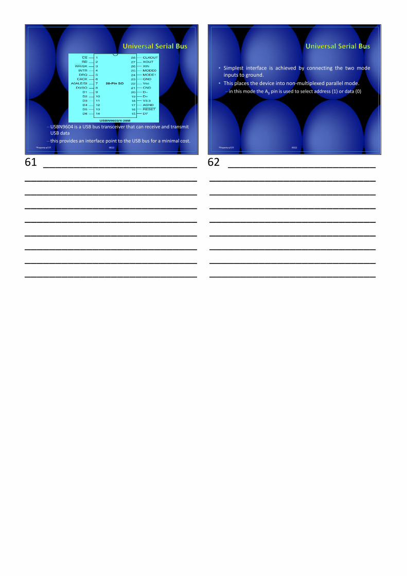
–USBN9604 is a USB bus transceiver that can receive and transmit USB data
– this provides an interface point to the USB bus for a minimal cost.
61 _________________________ ____________________________ ____________________________ ____________________________ ____________________________ ____________________________ ____________________________ ____________________________ ____________________________
*Property of STI I0022
• Simplest interface is achieved by connecting the two modeinputs to ground.
• This places the device into non-multiplexed parallel mode.
– in this mode the A0 pin is used to select address (1) or data (0)
62 ________________________ ___________________________ ___________________________ ___________________________ ___________________________ ___________________________ ___________________________ ___________________________ ___________________________