Embed Size (px)
Citation preview

INTERMITTENT COATING

BACKGROUND
• We.ng – Surface energy modifica=on
• Pump Control – Valve control (=ming) – Physical movement (=ming)
• Physical Posi=on – Liquid (vapor) adsorp=on
• Distance • Roughness • Concentra=on
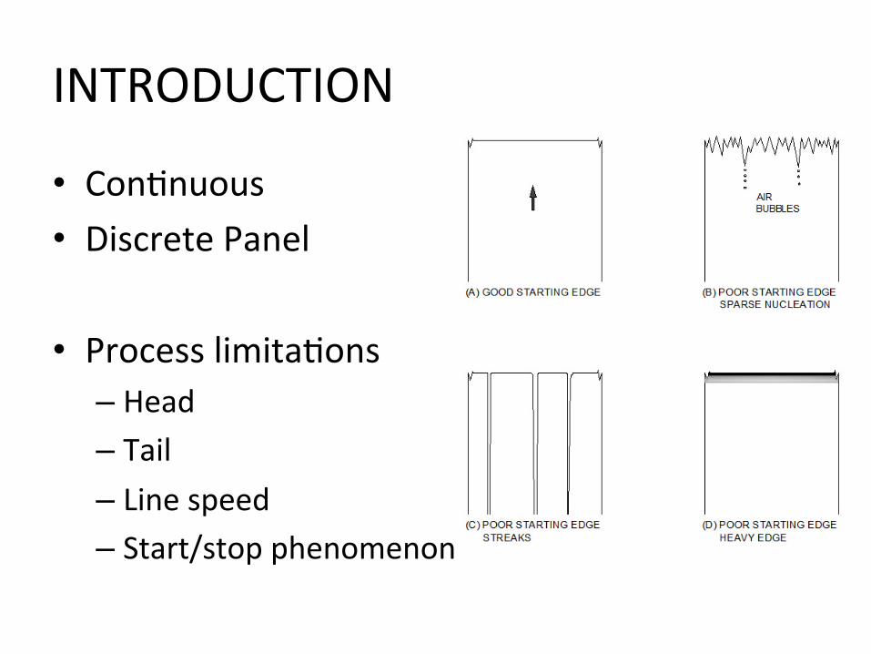
INTRODUCTION
• Con=nuous • Discrete Panel
• Process limita=ons – Head – Tail – Line speed – Start/stop phenomenon

PATENTS
• US 4,938,994 – Edward Choinski (1990)
• Flow control • Mechanical movement
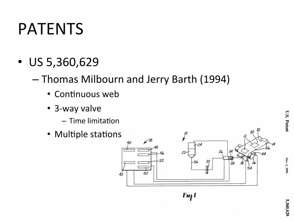
PATENTS
• US 5,360,629 – Thomas Milbourn and Jerry Barth (1994)
• Con=nuous web • 3-‐way valve
– Time limita=on
• Mul=ple sta=ons
PATENTS
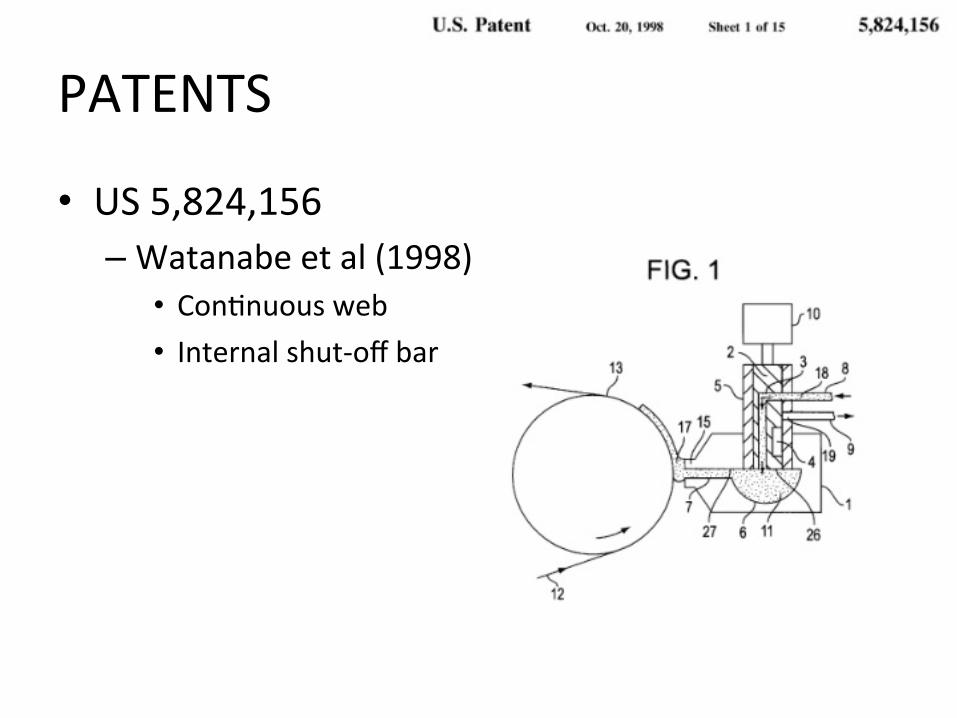
• US 5,824,156 – Watanabe et al (1998)
• Con=nuous web • Internal shut-‐off bar
SPECIFICATIONS • Coat width = 340 mm • Coat length = 680 mm • Intermibent coa=ng capability required up to 10 mpm (30
mpm in further study) with maximum 3 mm tail allowed • Crossweb varia=on tolerance based off weight (5 +/-‐0.15
mg/cm2). • Required coa=ng speed: at least 10 mpm for a slurry with
loading of 6 mg/cm2 and 50 solid % • Coa=ng edge quality to match crossweb coa=ng varia=on
capability • Tension control improvement to match downweb coa=ng
varia=on capability based off weight (5 +/-‐0.15 mg/cm2)
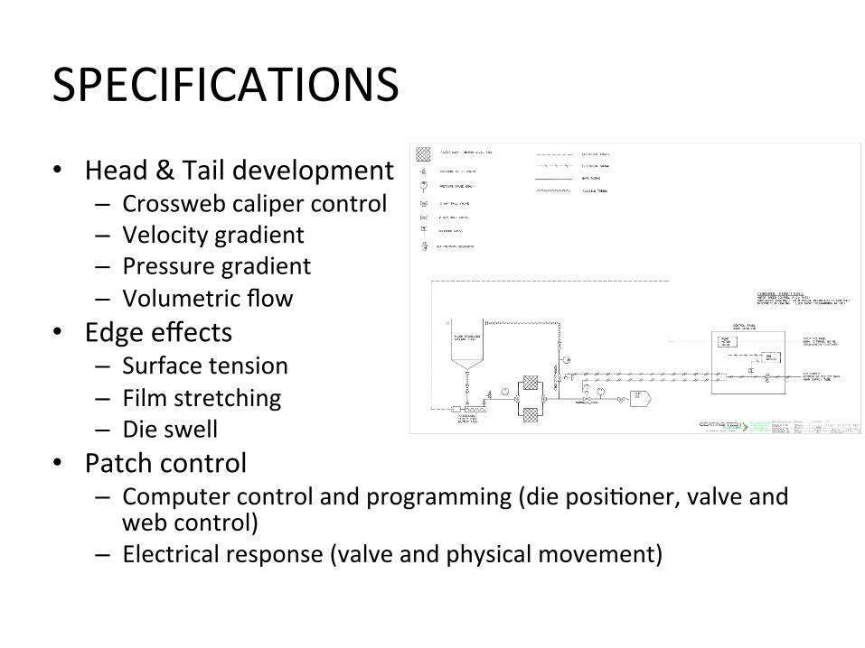
SPECIFICATIONS • Head & Tail development
– Crossweb caliper control – Velocity gradient – Pressure gradient – Volumetric flow
• Edge effects – Surface tension – Film stretching – Die swell
• Patch control – Computer control and programming (die posi=oner, valve and web control)
– Electrical response (valve and physical movement)
EXPERIMENTAL
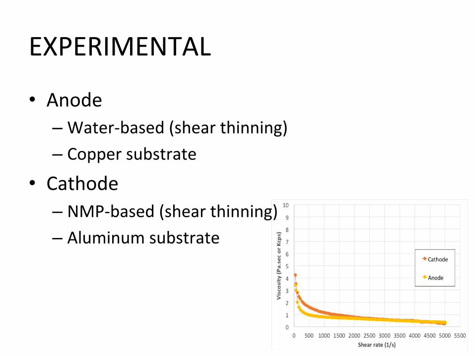
• Anode – Water-‐based (shear thinning) – Copper substrate
• Cathode – NMP-‐based (shear thinning) – Aluminum substrate

EXPERIMENTAL
• Slot die setup – Offset = 0 – Lip face (upstream and downstream) = 762 micron (0.030 inch)
– Shim thickness = 500 micron (20 mil) – Coa=ng gap = 25 micron (1 mil) – Coa=ng width = 340 mm (13.38 inch)

RESULTS
• Simula=on feedback – Pressure – Velocity – Volumetric flow – Mass flow
• Tension and compression – Flow stability – Stagna=on zones – Die swell

RESULTS • Line speed increase
– Parallellism worsens • We.ng • Reac=on =me
• Pressure increase – Fluid velocity increase – Measure and balance around valve
• Edge effects – Stresses (surface tension, film stretching or die swell) – Draw ra=o (substrate speed/fluid speed) – Slot die design and simula=on
• Air – Excessive fluid flow
CONCLUSION • 10 mpm acceptable applica=on speed • Best setup (reduced head/tail, reduced edge bead and improved parallel edge) – Flow control – Mechanical movement
• FUTURE – Increased line speed (30 mpm +) – Alterna=ve technologies – Mul=ple sta=ons – Surface modifica=on effect – Vacuum effect