Embed Size (px)
Citation preview

Basic ofCriteria, Strategy, and Process for a Proper Arctic Offshore
Field Development Plan
G. MoriccaSenior Petroleum Engineer

March 2017 G. Moricca 2
Contents
1. Oil and gas resources in the Arctic 2. Safety and Environment3. Field Development Plan Guideline4. Uncertainties Management and Risk Mitigation5. Norwegian Petroleum Directorate FDP Guideline6. Technical Topics:
Reservoir Model for the FDP
Project Economic Evaluation
Hydrocarbon Recovery
Well Architecture
Offshore Drilling Systems for Arctic conditions
Production System for Arctic conditions

March 2017 G. Moricca 3
Contents
1. Oil and gas resources in the Arctic 2. Safety and Environment3. Field Development Plan Guideline4. Uncertainties Management and Risk Mitigation5. Norwegian Petroleum Directorate FDP Guideline6. Technical Topics:
Reservoir Model for the FDP
Project Economic Evaluation
Hydrocarbon Recovery
Well Architecture
Offshore Drilling Systems for Arctic conditions
Production System for Arctic conditions

March 2017 G. Moricca 4
Oil and gas resources in the Arctic are large

March 2017 G. Moricca 5
The Norwegian Perspective – Petroleum activities in the Norwegian Barents Sea
First exploration activities started in 1980
Snøhvit gas field in production
Goliat oil field in production
Johan Castberg oil under evaluation
Alta and Gotha oil under evaluation
Wisting oil ready to be developed
Several smaller gas discoveries made
ref. ENI 21.3.16

March 2017 G. Moricca 6
Petroleum activities in the Norwegian Barents Sea
Goliat First oil field in the Barents
Sea – ENI as operator
Production with offshore loading started in March 2016
One of the largest industrial projects undertaken in Northern Norway
Developed on the basis of comprehensive impact assessments

March 2017 G. Moricca 7
The Barents Sea – an emerging petroleum frontier
The Delimitation Agreement between Norway and Russia in force July 7, 2011
An area like the North Sea split 50/50
Impact assessment carried out formally opening the Norwegian part of the Barents Sea East
Norway applies its concession policy in the new area
Russia has awarded its “new” acreage to stated owned Rosneft

March 2017 G. Moricca 8
OMV (Norge), a wholly owned subsidiary of OMV Exploration, has discovered oil at wildcat well 7324/8-1, WistingCentral, in exploration license PL 537 in Norway.
OMV discovers oil at Wisting Central well, Barents Sea

March 2017 G. Moricca 9
Arctic offshore area has a great potential for future field developments projects, however they are characterized by:
1. High ecological risks
2. Challenging environment for operation and construction
3. Huge money investments

March 2017 G. Moricca 10
Arctic Challenges Severe environmental conditions
Difficult soil conditions
High environmental risks
Remoteness from the market
Ice and ice features
Icebergs
Ridges
Polar lows
Low temperatures
Darkness
Fog

March 2017 G. Moricca 11
Contents
1. Oil and gas resources in the Arctic 2. Safety and Environment3. Field Development Plan Guideline4. Uncertainties Management and Risk Mitigation5. Norwegian Petroleum Directorate FDP Guideline6. Technical Topics:
Reservoir Model for the FDP
Project Economic Evaluation
Hydrocarbon Recovery
Well Architecture
Offshore Drilling Systems for Arctic conditions
Production System for Arctic conditions

March 2017 G. Moricca 12
Safety and Environment Safety and Environment have become important elements of
all part of field life cycle, and involve all of the technical and support functions in the oil company.
The Piper Alpha disaster in North Sea in 1988 triggered a major change in the approach to management of safety within the industry.
Companies recognize that good safety and environmental management make economic sense and are essential to guaranteeing long-term presence in the market.
Stakeholders, be they governments, non-government organizations (NGOs) or financing entities will scrutinize the HSE (health, safety and environment) performance of an operator on a continuous basis.
Many techniques have been developed for the safety and environmental impact of operations.

March 2017 G. Moricca 13
Safety Performance Standards Safety Performance is measured by companies in many different
ways. To benchmark safety performance on an industry wide scale, globally recognized standard are required.
A commonly used method is the recording of the number of accidents, or lost time incidents (LTI).
An LTI is an incident which causes a person to stay away from work for one ore more days.
Recordable injury frequency (RIF) is the number of injuries that require medical treatment per 100 employee.

March 2017 G. Moricca 14
Hazard and operability studies -HAZOP
Techniques such as Hazard and operability studies (HAZOP) are used to design of plant layout and equipment.
This type of study is now commonly applied to new platform design and to the evaluation of refurbishment on existing platform.
This technique involves determining the potential hazard of an operation under normal and abnormal operating conditions, and considering the probability and consequences of an accident.

March 2017 G. Moricca 15
Innovations in Platform Design
Freefall lifeboats, launched from heat shielded slipways on offshore platforms;
Emergency shutdown valves installed on the seabed and topsides in incoming and outgoing pipelines, designed to isolate the platform from all sources of oil and gas in an emergency;
Fire resistant coating on structural members;
Computerized control and shutdown of process equipment.
Some example of innovations in platform design are:
Physical separation of accommodation modules from the drilling/process/compression modules - creating a pressurized “safe haven”. The areas are at the opposite ends of the platform, and ere separated by fire and blast walls;

March 2017 G. Moricca 16
Safety Management System
The SMS typically addresses the following areas:
Organization structure
Management personnel standards
Design procedures
Procedures for operations, maintenance, modifications and emergencies
Management of safety by contractors in respect of their work
The involvement of the workforce in safety
Accident and incident reporting, investigation and follow-up
Monitoring and auditing the operation of the system
Systematic reappraisal of the system.
Major oil companies have each developed their own specific safety management system (SMS) to suit local environments and modes of operation.

March 2017 G. Moricca 17
Environment Environmental standards have become a critical part of
any business.
Whilst individual companies tend to have their own specific environmental management system (EMS), global standards have been established, such as ISO 14001.
Since its principles are generic, they can be applied to almost any type of organization and many large oil and gas companies have adopted its framework.
Adherence to environmental standards is not only required to meet the legislative requirements in host countries, but is also viewed as good business because it is:- Cost effective- Providing a competitive edge- Essential to ensuring continued operations in an area- Helpful in gaining future operations in an area.

March 2017 G. Moricca 18
Environment Impact Assessment - EIA
The objective of an EIA is to document the potential physical, biological, social and health effect of a planned activity.
Typically, the EIAs will be carried out for:- Seismic- Exploration and appraisal drilling- Development drilling and facilities installation- Production operations- Decommissioning and abandonment.
This will enable decision makers to determine whether an activity is acceptable and if not, identify possible alternatives.

March 2017 G. Moricca 19
The EIA Process The EIA process is a systematic process that examines the
environmental consequences of development action in advance.
The key stages in a EIA process includes:- Screening: undertaken to decide which project should be subject to
environmental assessment.- Scoping: identifies, at an early stage, the most significant issues to be
included in the EIA.- Consideration of alternatives: seeks to ensure that the proposer has
considered other feasible options including location, scales, process, layouts, operating conditions and ‘’no action’’ option.
- Project description: includes a clarification of the purpose and rationale of the project.
- EIA preparation: is the scientific and objective analysis of the scale, significance and importance of impacts identified.
- Public consultation and participation: aims to assure the quality, comprehensiveness and effectiveness of the EIA.

March 2017 G. Moricca 20
..... The EIA Process
The key stages in a EIA process includes:- EIA presentation: a vital step in the process, the documentation serves to
communicate the findings of EIA process to interested parties.- Review: involves a systematic appraisal by a government agency or
independent review panel.- Decision-making on the project involves a consideration by the relevant
authority of the EIA together with any material considerations.- Monitoring: is normally adopted as a mechanism to check that any
conditions imposed on the project are being enforced or to check the quality of the affected environment.
- Auditing: follows on from monitoring. Auditing is being developed to test the scientific accuracy of impact predictions and as a check on environmental management practices. It can involve comparing actual outcomes with predicted outcomes, and can be used to assess the quality of predictions and effectiveness of mitigation. It provides vital feedback into the EIA process.

March 2017 G. Moricca 21
Contents
1. Oil and gas resources in the Arctic 2. Safety and Environment3. Field Development Plan Guideline4. Uncertainties Management and Risk Mitigation5. Norwegian Petroleum Directorate FDP Guideline6. Technical Topics:
Reservoir Model for the FDP
Project Economic Evaluation
Hydrocarbon Recovery
Well Architecture
Offshore Drilling Systems for Arctic conditions
Production System for Arctic conditions

March 2017 G. Moricca 22
Field Development Planning is the process of evaluating multiple development options for a field and selecting the best option based on assessing tradeoffs among multiple factors:
Net present value, typically the key driver of decisions for publicly-traded operators.
Oil and gas recovery
Operational flexibility and scalability
Capital versus operating cost profiles
Technical, operating and financial risks.
Field Development Planning (FDP)

March 2017 G. Moricca 23
FDP Integrated TeamAn integrated, multidisciplinary team approach is required for a proper FDP definition. The team should include the following professionals:
Geologists responsible for geological and petrophysical works.
Reservoirs engineers responsible for providing production forecast and economical evaluation.
Drilling engineers responsible for drilling offshore drilling systems selection and drilling operations.
Completion engineers responsible completion design and operations.
Surface engineers responsible for designing/selection surface and processing facilities.
Other professionals, if needed, such as pipeline engineers, land manager, etc.

March 2017 G. Moricca 24
The life Cycle of a Petroleum ReservoirThe major phases are:
Exploration Survey to find a new reservoir in a known field or to extend the
limit of a known oil or gas reservoir.
Discovery
Appraisal to establish the limits of the reservoir, the productivity of wells in it
and the properties of the oil or gas)
Field Development Plan (FDP) definition: If appraisal wells show the
reservoir to be technically and commercially viable, the Oil Company will produce
a development plan which will be submitted to the relevant authorities.
Drilling and Completion (Field development)
Construction Production
De-commissioning

G. Moricca 25
EXPLORATION – SEISMIC SURVEY
EXPLORATION DRILLING &
APPRAISAL DRILLING
CONSTRUCTION PHASE -
Detailed Design, Procurement, Fabrication
CONSTRUCTION PHASE –
Transportation, Installation, Hook-up and
Commissioning.
PRODUCTION/PROCESSING/ EXPORTING
Decommissioning of offshore Facility:
Basic steps include:
- Engineering and Planning;
- Permits and Regulatory Compliance;
- Platform Preparation;
- Well Plugging and Abandonment;
- Conductor Removal;
- Mobilization of Decommissiong Vessel;
- Topsides Removal;
- Jacket Removal;
- Pipeline and Umbilicals Decommissioning;
- Materials Disposal;
- Site Clearance and Restoration.
CONSTRUCTION PHASE -
Subsea Pipeline to Onshore Refinery
From Exploration to Decommissioning
WHEN THE RESERVOIR IS DEPLETED, THE
FACILITIES MUST BE DECOMMISSIONED.
March 2017
CONCEPT - FEED

March 2017 G. Moricca 26
Clear Target Identification
Identification of a Clear Target
based on the data collected
during the field appraisal and
in line with company strategy.
Use the reservoir numerical
model as a key tool to
determine the optimum
method of recovering the
hydrocarbons from the
reservoir.

March 2017 G. Moricca 27
Identification of a FDP Clear StrategyIdentify the most effective strategy to reach the predefined Company Target finding a proper answer to the questions like the following:
Reservoir hydrocarbon withdrawal strategy:- natural depletion- water and/or gas injection ?
Optimum wells location and spacing ?
Optimum plateau rate ?
Stand-alone development or subsea tie-in to existing platform(s) ?
Platform or subsea-to-land solution ?
Platform concepts (e.g. floating or fixed, with and without drilling facilities) ?
Integration with existing platform(s) or infrastructure ?
Transport solution for oil: pipeline transport or offshore loading ?
Transport solution for gas (compression demand, processing requirements) ?
Design for easy decommissioning and removal ?

March 2017 G. Moricca 28
In choosing a development concept the following shall be taken into consideration:
Reservoir data
Crude oil characteristics
Type of Drilling and Completion
Risk of pollution
Geographic location
Water depth
Distance from Shore Base and/or Terminal
Environmental conditions
Soil criteria
Functional and operational requirements
Governing Codes of Practice
Special or unusual Design Codes

March 2017 G. Moricca 29
The following risk events should be considered in order to identify the most safety development option:
Change of reservoir information, well type and future growth
Damage to pipelines/umbilicals due to mooring lines or anchor failure
Equipment failure during commissioning and starting up
Infrastructure/pipelines failure during installation
Delay of infrastructure to start up
Problems during well construction
Control system failures during operation
Flow assurance problems/plug formation
Slug catcher flooding
Hurricanes

March 2017 G. Moricca 30
Process for FDP Definition
Sensitivity Analysis for Optimization
NPVROCE (NPV/ Capital)
Reservoir Geologic Setting
Volumes in Place
Hydrocarbon Properties
Driving Mechanism
Driving Mechanism Efficiency
Ultimate Recovery Factor
Today an Tomorrow Oil Price
Uncertainties
Type Surface Facilities
Diameter Export Pipeline
Type and Nr of Wells
Decisions

March 2017 G. Moricca 31
Field Development Plan Workflow
1• Development & Depletion Strategies
2• Environmental Considerations
3• Data Acquisition and Analyses
4• Geological and Numerical Model Studies
5• Reserves and Production Forecast
6• Facilities Requirements
7• Economic Optimization
8• Management Approval

March 2017 G. Moricca 32
Industrial accepted Offshore Field Development Pan Methodology
Phase 1: Conceptual Design - (Appraise)
Phase 2: Feasibility (FDP definition)
Phase 3: Detail Design (Finalize)
Phase 4: Material Procurement, Construction and Installation
Phase 5: Production Start-up

March 2017 G. Moricca 33
Project Phases and their Objectives Phase
Objective
Ability toImpact Results
CapitalExpenditures

March 2017 G. Moricca 34
Early Planning Creates the Greatest Value
• Developing a robust reservoir model and depletion plan
• Optimizing the drilling program (greatest recovery with fewest wells)
• Minimizing well performance uncertainty
• Selecting the right surface facility plan
The greatest value to a project is created in the Appraise and Select phases which involve:
The spend in these phases is generally a small percentage of total development spend but provides substantial added value to the project

March 2017 G. Moricca 35
Planning is a Collaborative Process
Objective is to select a development plan that satisfies an Operator’s commercial, strategic and risk objectives
It involves a continuous interaction between key elements:- Subsurface - Surface - Business
The process requires continuous and effective collaboration and alignment between reservoir, well construction, surface facilities and commercial teams
Sub
Surface
SurfaceBusiness

March 2017 G. Moricca 36
Relative Influence on Cost
The “right” choice of the concept for the offshore field development is the first and major step for achieving profitable and technically safe offshore field exploitation.

March 2017 G. Moricca 37
To avoid uneconomic development
To ensure safety for Person, Environment
To ensure adequate economic return
To derive maximum benefit from available data sets
To improve reservoir recovery
Focus of Development Strategy
Emphasis on:
Reduction of uncertainties
Reduction of influence of uncertainties

March 2017 G. Moricca 38
Proper Planning is Critical to Success

March 2017 G. Moricca 39
Feasibility
Does the technology exist?
Is it technically feasible?
Can it be built to the required size?
Can it be installed?
Do the risks appear manageable?

March 2017 G. Moricca 40
Concept Selection
Which concept will have the highest NPV?
Constructability and install ability issues
Site conditions
Potential contracting constraints
Risk analysis

March 2017 G. Moricca 41
Front End Engineering Design – FEED
Strive for a fabrication friendly design
Strive for an installation friendly design
Identify risks and develop mitigation plans
Develop a manageable contracting strategy
Develop a realistic cost estimate and schedule

March 2017 G. Moricca 42
Engineering, Procurement, Construction, and Installation - EPCI Phase
Reflects pre-sanction planning Focus becomes ‘work the plan’ Inadequate planning leads to serious
problems Recovery is expensive

March 2017 G. Moricca 43
Contents
1. Oil and gas resources in the Arctic 2. Safety and Environment3. Field Development Plan Guideline4. Uncertainties Management and Risk Mitigation5. Norwegian Petroleum Directorate FDP Guideline6. Technical Topics:
Reservoir Model for the FDP
Project Economic Evaluation
Hydrocarbon Recovery
Well Architecture
Offshore Drilling Systems for Arctic conditions
Production System for Arctic conditions

March 2017 G. Moricca 44
Discoveries are more complex in structure, divided by regional and local Faults into Blocks.
Reservoir & Fluid properties are difficult to predict.
Information acquired during exploration & appraisal period is not sufficient to plan a full field development.
Uncertainties Management

March 2017 G. Moricca 45
To reduce the risks of an improper FDP and avoid a financial catastrophe, the field can be developed in more than one single phase.
Risk Mitigation
An early production system tied back to a 2-3 years leased floating, production, storage and offloading vessel (FPSO) could be an valid alternative
For the first phase, facilities should be installed with low cost, but flexible to upgrade for future field development and production.

March 2017 G. Moricca 46
Contents
1. Oil and gas resources in the Arctic 2. Safety and Environment3. Field Development Plan Guideline4. Uncertainties Management and Risk Mitigation5. Norwegian Petroleum Directorate FDP Guideline6. Technical Topics:
Reservoir Model for the FDP
Project Economic Evaluation
Hydrocarbon Recovery
Well Architecture
Offshore Drilling Systems for Arctic conditions
Production System for Arctic conditions

March 2017 G. Moricca 47
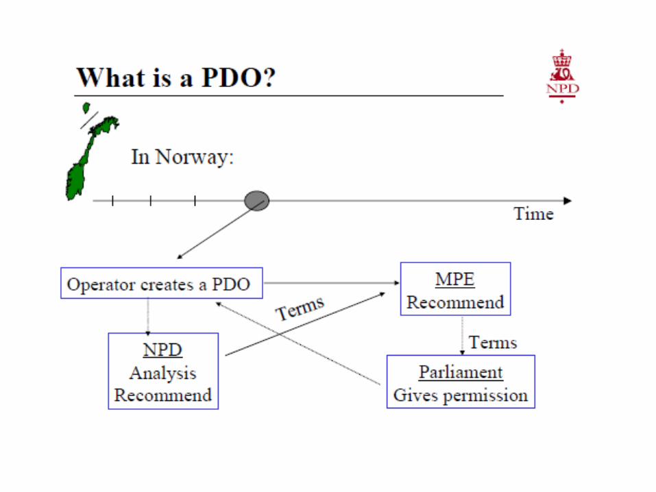
Norwegian Petroleum Directorate FDP Guideline
Source: Jan Bygdevoll
Discipline leader Reservoir Engineering
Norwegian Petroleum Directorate
February 2006

March 2017 G. Moricca 48

March 2017 G. Moricca 49

March 2017 G. Moricca 50

March 2017 G. Moricca 51

March 2017 G. Moricca 52

March 2017 G. Moricca 53

March 2017 G. Moricca 54

March 2017 G. Moricca 55

March 2017 G. Moricca 56

March 2017 G. Moricca 57

March 2017 G. Moricca 58

March 2017 G. Moricca 59

March 2017 G. Moricca 60

March 2017 G. Moricca 61

March 2017 G. Moricca 62
March 2017 G. Moricca 63

March 2017 G. Moricca 64

March 2017 G. Moricca 65

March 2017 G. Moricca 66

March 2017 G. Moricca 67
Contents
1. Oil and gas resources in the Arctic 2. Safety and Environment3. Field Development Plan Guideline4. Uncertainties Management and Risk Mitigation5. Norwegian Petroleum Directorate FDP Guideline6. Technical Topics:
Reservoir Model for the FDP
Project Economic Evaluation
Hydrocarbon Recovery
Well Architecture
Offshore Drilling Systems for Arctic conditions
Production System for Arctic conditions

March 2017 G. Moricca 68
Development and Depletion Strategy The input of all disciplines, mutual understanding and inter-discipline
communication is the key to developing a successful optimum plan.
In order to come up with an economically viable development and depletion strategy, the team need to address the following main questions:
1. Recovery scheme: - natural depletion or
- natural depletion
augmented by fluid
(water or gas)
injections
2. Well spacing –number of wells, platforms, reserves, and economics
3. Type of well: vertical, slanted, horizontal, multi-lateral

March 2017 G. Moricca 69
The success of oil and gas FDP is largely determined by the reservoir: its size, complexity, productivity and the type and quantity of fluid it contains. To optimize a FDP, the characteristics of the reservoir must be well defined. Unfortunately, in some cases, a level of information available is significantly less than that required for an accurate description of the reservoir and estimates of the real situation need to be made.
Reservoir Model a Standard Tool for FDP
Reservoir numerical model is a standard tool in petroleum engineering for solving a variety of fluid flow problems involved in recovery of oil and gas from the porous media of reservoirs.
Typical application of reservoir simulation is to predict future performance of the reservoirs so that intelligent decisions can be made to optimize the economic recovery of hydrocarbonsfrom the reservoir. Reservoir simulation can also be used to obtain insights into the dynamic behavior of a recovery process or mechanism.
Reservoir Model
Outcomes
dictate
Volumes
Rates
Well
Architecture
Well Completion
Surface
Facilities

March 2017 G. Moricca 70
Major Tasks of the Reservoir Engineers How much oil and gas is originally in place?
What data are needed to answer these questions?
What are the drive mechanisms for the reservoir?
What are the trapping mechanisms for the reservoir?
What will the recovery factor be for the reservoir by primary depletion?
What will future production rates from the reservoir be?
How can the recovery be increased economically?

Data required to build a reservoir modelClassification Data
AcquisitionTiming
Responsibility
SeismicStructure, stratigraphy, faults, bed thickness, fluids, inter-well heterogeneity
Exploration Seismologists, Geophysicist
GeologicalDepositional environment, diagenesis, lithology, structure, faults, and fractures
Exploration, discovery & development
Exploration & development geologists
LoggingDepth, lithology, thickness, porosity, fluid saturation, gas/oil, water/oil and gas/water contacts, and well-to-well correlations
DrillingGeologists, petrohysicists, and engineers
Coring DrillingGeologists, drilling and reservoir engineers, and laboratory analysts
BasicDepth, lithology, thickness, porosity, permeability, and residual fluid saturation
SpecialRelative permeability, capillary pressure, pore compressibility, grain size, and pore size distribution
FluidFormation volume factors, compressibilities, viscosities, chemical compositions, phase behavior, and specific gravities
Discovery, delineation, development, and production
Reservoir engineers and laboratory analysts
Well Test
Reservoir pressure, effective permeability-thickness, stratification, reservoir continuity, presence of fractures or faults, productivity and injectivity index, and residual oil saturation
Discovery, delineation, development, and production and injection
Reservoir and production engineers
Production & Injection
Oil, water, and gas production rates, and cumulative production, gas and water injection rates and cumulative injections, and injection and production profiles
Production & InjectionProduction and reservoir engineers

March 2017 G. Moricca 72
Data Acquisition and Analysis Multidisciplinary groups (i.e. geophysicists, geologists,
petrophysicists, drilling, reservoir, and production engineers) are involved in collecting various types of data throughout the exploration and appraisal phases.
An effective data acquisition and analysis program requires careful planning and well-coordinated team efforts.
Coring, logging, and initial reservoir fluid sampling should be made at appropriate times using the proper procedures and analyses

March 2017 G. Moricca 73
Reservoir model is an integrated modelling tool, prepared jointly by geoscientists and engineers.
Reservoir model building
The integrated reservoir model requires a thorough knowledge of the geology, rock and fluid properties.
The geological model is derived by extending localized core and log measurement to the full reservoir using many technologies such as geophysics, mineralogy, depositional environment, and diagenesis.

March 2017 G. Moricca 74
Reservoir Model Capabilities The geological model defines the “geological units” and their continuity and
compartmentalization.
The geological model
combined with the dynamic
model provides a means (the
reservoir model) of
understanding the current
performance and predicts the
future performance of the
reservoir under various “what
if” conditions so that better
reservoir exploitation
decisions can be made.

March 2017 G. Moricca 75
An example of iterative processes of use of the reservoir model for a field development project

March 2017 G. Moricca 76
Reserves estimation by Volumetric Method At the very early stage, when the reservoir
model is not available yet, a preliminary project evaluation can be made on the base of reserves estimated by a volumetric calculation.
The volumetric method for estimating recoverable reserves consists of determining the original oil in place (OOIP) and then multiply OOIP by an estimated recovery factor.
The OOIP is given by the bulk volume of the reservoir, the porosity, the initial oil saturation, and the oil formation volume factor.
The bulk volume is determined from the isopach map of the reservoir, average porosity and oil saturation values from log and core analysis data, and oil formation volume factor from laboratory tests or correlations.

March 2017 G. Moricca 77
Areal Extent (productive limits of reservoir)- Structure map- Seismic- Analogy
Net pay thickness- Well logs
Porosity- Well log or cores
Water saturation- Well logs or cores
Recovery efficiency- Analogy- Drive mechanism- Reservoir characteristics
… for reserves estimation by volumetric method the following data are required:

March 2017 G. Moricca 78
Calculating Oil in Place by the Volumetric Method
Oil in place by the volumetric method is given by:
Where:
N(t) = oil in place at time t, STB
Vb = 7758 A h = bulk reservoir volume, bbl
7758 = bbl/acre-ft
A = area, acres
h = thickness, ft
φ(p(t)) = porosity at reservoir pressure p, fraction
Sw(t) = water saturation at time t, fraction
Bo(p(t)) = oil formation volume factor at reservoir pressure p, bbl/STB
p(t) = reservoir pressure at time t, psia

March 2017 G. Moricca 79
Contents
1. Oil and gas resources in the Arctic 2. Safety and Environment3. Field Development Plan Guideline4. Uncertainties Management and Risk Mitigation5. Norwegian Petroleum Directorate FDP Guideline6. Technical Topics:
Reservoir Model for the FDP
Project Economic Evaluation
Hydrocarbon Recovery
Well Architecture
Offshore Drilling Systems for Arctic conditions
Production System for Arctic conditions

March 2017 G. Moricca 80
Project Economic Evaluation
3. Collecting operation and economic data (see the dedicated Tab).
4. Making economic calculations. Engineers and geologists are primarily responsible.
5. Making risk analysis and choosing optimum project. Both engineers and geologists are primarily responsible for analysis. Engineers, geologists, operations staff, and management work together to decide on the optimum project.
The task in project economic analysis require team efforts consisting of:
1. Setting an economic objective based on the company’s economic criteria. Reservoir engineers are responsible for developing justification with the input from management.
2. Formulating scenarios for project development. Engineers and geologists are the primary contributors with management guidance.

March 2017 G. Moricca 81
Input Data for the Project Economic Evaluation
Data Source / CommentExpected oil and gas production Reservoir engineers
Rates vs. time Reservoir and production engineers
Oil and gas price Finance and economics professionals
Capital investment(tangible, intangible) and operating costs
Facilities, operations and engineering professional
Royalty/production sharing Unique to each project
Discount and inflation rate Finance and economics professionals
State and local taxes (production, severance, ad valorem, etc.)
Accountants
Income taxes, depletion, and amortization schedules
Accountants

March 2017 G. Moricca 82
Economic Evaluation Criteria Each company has its own economic evaluation criteria with
required minimum values to fit its strategy for doing business profitability.
Acceptance or rejection of individual proposals are largely governed by the company’s economic criteria.
Commonly used criteria are reviewed, for our convenience, as follow:
1. Payout of Time2. Profit-to-Investment Ratio3. Present Worth Net Profit (PWNP)4. Investment Efficiency or Present Worth Index or Profitability
Index5. Discounted Cash Flow Return on Investment or Internal Rate
of Return.

March 2017 G. Moricca 83
Payout of Time
Payout of time is the time needed to recovery the investment.
It is the time when the cumulative undiscounted or discounted cash flow (CF = revenue – capital investment – operating expenses) is equal zero.
The shorter the payout time (2 to 5 years), the more attractive the project.
Although it is an easy and simple criterion, it does not give the ultimate lifetime profitability of the project, and it should not used solely for assessing the economic viability of project.

March 2017 G. Moricca 84
Profit-to-Investment Ratio
Profit-to-Investment Ratio is the undiscounted cash flow without capital investment divided by the total investment.
Unlike the payout time, it reflects total profitability; however, it does not recognize the tine value of money.
Present Worth Net Profit (PWNP) is the present value of the entire cash flow discounted at a specified discount rate.
Present Worth Net Profit (PWNP)

March 2017 G. Moricca 85
Investment Efficiency or Present Worth Index or Profitability Index
Investment Efficiency or Present Worth Index or Profitability Index is the total discounted cash flow divided by the total discounted investment.
The value of this parameter in the range of 0.5 to 0.75 is considered favorable

March 2017 G. Moricca 86
Discounted Cash Flow Return on Investment or Internal Rate of Return is the maximum discount rate that needs to be charged for the investment capital to produce a break-even.
Discounted Cash Flow Return on Investment or Internal Rate of Return.
This can be also expressed as the discount rate at which the total discounted cash flow excluding investments is equal to the discounted investments over the life of the project.

March 2017 G. Moricca 87
SomeEconomics Criteria
ofNorwegian Petroleum
Directorate

March 2017 G. Moricca 88

March 2017 G. Moricca 89

March 2017 G. Moricca 90
Contents
1. Oil and gas resources in the Arctic 2. Safety and Environment3. Field Development Plan Guideline4. Uncertainties Management and Risk Mitigation5. Norwegian Petroleum Directorate FDP Guideline6. Technical Topics:
Reservoir Model for the FDP
Project Economic Evaluation
Hydrocarbon Recovery
Well Architecture
Offshore Drilling Systems for Arctic conditions
Production System for Arctic conditions

March 2017 G. Moricca 91
Impact of Hydrocarbon Recovery on FDP
The reservoir and well behavior under dynamic conditions are the key parameters in determining what fraction of the hydrocarbon initial in place (HCIIP) will be produced over the lifetime of the field.
This behavior will therefore dictate the revenue stream which the development will generate through sales of the hydrocarbons.
The reservoir and well performance are linked to the surface development plan, and cannot be considered in isolation; different subsurface development plans will demand different surface facilities.
The prediction of reservoir behavior are therefore crucial components of field development plan.

March 2017
The Driving Force for Production Reservoir fluids (oil, water, gas) and rock matrix are contained under high temperature and
pressures; they are compressed relative to their densities at standard temperature and pressure. Any reduction in pressure on the fluids or rock will results in an increasing volume, according to their compressibility.
As underground fluids are withdrawn (i.e. production occurs) any free gas present expands readily to replace the voidage, with a small drop in reservoir pressure. If only oil or water were present in the reservoir system, a much greater reduction in reservoir pressure would be experienced for the same amount of production.
The expansion of the reservoir fluids, which is function of their volume and compressibility. Act as a source of drive energy which can act to support primary production from the reservoir.
Initial ConditionsPinitial
After ProductionPactual << Pinitial
Primary production means using the natural energy stored in the reservoir as a drive mechanism for production.

March 2017
Enhancement Hydrocarbon Recovery Process
Waterflooding is one of the most widely used post-primary recovery method. Reservoir engineers are responsible for waterfooddesign, performance prediction, and reserves estimation. They share responsibilities with production engineers for the implementation, operation.
Waterfooding is the injection of water into a wellbore to push, or “drive” oil to another well where it can be produced. The principal reason for waterflooding an oil reservoir is to increase the oil-production rate and, ultimately, the oil recovery.
William M. Cobb & Associates, Inc.
G. Moricca 93
This is accomplished by "voidage replacement"—injection of water to increase the reservoir pressure to its initial level and maintain it near that pressure.
The water displaces oil from the pore spaces, but the efficiency of such displacement depends on many factors (e.g., oil viscosity and rock characteristics).

March 2017 G. Moricca 94
Waterflooding Waterflooding in an intensive investment activity and require a proper design. The design
includes: - Injection/producer pattern layouts - Injection-water sensitivity studies - Injection wells, injectivity, and allocation approaches, including well fracturing - Pilot waterflooding- Production wells - Surface facilities for injection water - Surface facilities for produced fluids
ProducersInjectors
Offshore Surface FacilitiesSeawater for Injection and sulfate reduction

March 2017 G. Moricca 95
In oil fields such as Wilmington (California, US) and Ekofisk (North Sea), voidage replacement also has been used to mitigate additional surface subsidence. In these cases, the high porosity of the unconsolidated sandstones of the Wilmington oil field’s reservoirs and of the soft chalk reservoir rock in the Ekofisk oil field had compacted significantly when the reservoir pressure was drawn down during primary production.
Waterflooding - Ekofisk Case Study
Sept. 2011

March 2017 G. Moricca 96
Contents
1. Oil and gas resources in the Arctic 2. Safety and Environment3. Field Development Plan Guideline4. Uncertainties Management and Risk Mitigation5. Norwegian Petroleum Directorate FDP Guideline6. Technical Topics:
Reservoir Model for the FDP
Project Economic Evaluation
Hydrocarbon Recovery
Well Architecture
Offshore Drilling Systems for Arctic conditions
Production System for Arctic conditions

March 2017 G. Moricca 97
Well Planning The drilling of a well involves a major investment ranging from a few million
US$ for onshore well to 100 million US$ for a deepwater exploration well.
Well engineering is aimed at maximizing the value of this investment by employing the most appropriate technology and business process, to drill a ‘’fit for purpose” well, at the minimum cost, without compromising safety or environmental standards.
The subsurface team will define optimum location for the planned wells to penetrate the trajectory through the objective sequence.
To optimize the design of a well it is desirable to have as accurate a picture as possible of the subsurface.

March 2017 G. Moricca 98
Well Shape Selection CriteriaThe well shape should be selected based on the geological target, maximization
of the hydrocarbon recovery, and operational constraints

March 2017 G. Moricca 99
Well Architecture Today, thanks to the advanced drilling technologies it is possible to drill wells
having different shapes: - Vertical- Slanted- S-shape- Horizontal- Multilateral
This gives us the flexibility to select the most appropriate, according to the production target and the subsurface formation characteristics.
Well Type by Shape
J-shaped S-shaped Inclined well Horizontal well

March 2017 G. Moricca 100
Vertical Well
Vertical well is the ideal solution to produce from a single flow unit having a large net pay or multiple flow units can be produced commingled.
Easy to be drilled.
Very good bottomholeaccessibility.
Less expensive.

March 2017 G. Moricca 101
Horizontal Well
Disadvantages of horizontal wells are:- High cost as compared to a
vertical well.- Generally only one zone at a time
can be produced using a horizontal well.
- If the reservoir has multiple pay-zones, especially with large differences in vertical depth, or large differences in permeability, it is not easy to drain all the layers using a single horizontal well..
Horizontal wells have been employed in a variety of reservoir applications:- Thin zones- Naturally fractured reservoirs,- Reservoirs with water and gas coning problems- Low permeability reservoirs- Gas reservoirs- Heavy oil reservoirs- Waterflooding- EOR applications.

March 2017 G. Moricca 102
Horizontal Well – CHEVRON Case study Horizontal Well Technology Applications for Improved Reservoir Depletion, Kern River Oil Field
Estimated to have over 3.5 billion barrels of original oil in place, the 114 year old Kern River Oil Field was a sleeping giant until the late 1960's when steam flooding began and oil production ramped up from 19,000 to over 142,000 BOPD by the mid 1980's.
In 2007 the cumulative production reached two billion barrels of heavy oil. With the introduction of convectional and shallow horizontal wells in 2007 the production decline curve that had been at approximately 6% began to flatten and today the decline rate is at 1 to 2%.

March 2017 G. Moricca 103

March 2017 G. Moricca 104

March 2017 G. Moricca 105
Multi-lateral Well Technologies have been developed to
drill multi-lateral wells. These wells have various shapes and offer the possibility of different types of completions to isolate and control production from different branches of multi-laterals.
Multi-lateral applications are common in heavy oil reservoirs (where wells are completed with slotted liners) and in carbonate reservoirs using open hole completions. A large scale of applications of multi-laterals is found in the heavy oil reservoirs in Canada and Venezuela and in the carbonate reservoirs in the Middle East.5,6Thin zones

March 2017 G. Moricca 106
Multilateral Well – ENI Case study The Zatchi B Heavy Oil Reservoir Development: The Unique Challenges of the TAML6 Multilateral Well
The Zatchi, located in the Lower Congo Basin offshore, is a shallow multi-layer reservoir (avg top @ -400 n TVDSS) .
The Zatchi B reservoir is 300m thik sand characterized by a large accumulation of heavy and viscous oil (15o API, 1000 cP).
Aquifer
- 406,5 m
- 419,5 m

March 2017 G. Moricca 107
Contents
1. Oil and gas resources in the Arctic 2. Safety and Environment3. Field Development Plan Guideline4. Uncertainties Management and Risk Mitigation5. Norwegian Petroleum Directorate FDP Guideline6. Technical Topics:
Reservoir Model for the FDP
Project Economic Evaluation
Hydrocarbon Recovery
Well Architecture
Offshore Drilling Systems for Arctic conditions
Production System for Arctic conditions

March 2017 G. Moricca 108
The main problems for drilling in Arctic conditions would be a short ice-free period and ice loads on the drilling facility. Thus not every drilling facility is applicable for an Arctic Area.
Main traditional drilling solutions for offshore field development are described and their suitability for Arctic conditions is considered.
Drilling system for Arctic conditions

March 2017 G. Moricca 109
Drilling barges Drilling barges are big floating structures grounded on the bottom that need to
be tugged on the drilling point. They are ballasted to sink on the bottom before drilling. They are often used in shallow inner waters as bogs, lakes and other shallow
waters. However they are inappropriate for the wave condition characteristics for the
open waters in Arctic Area.

March 2017 G. Moricca 110
Grounded submersibledrilling platform Grounded submersible drilling rigs are grounded on the bottom and suitable for the
shallow waters. These drilling platforms consist of two blocks located one on another. Living quarters and
drilling rig are located in the upper block. The lower block works as an outer casing of a submarine - when the platform moves from one place to another, the lower block is filled by air which makes the platform to float. When such drilling platform is installed on the location, the air is bleed and the platform is grounded on the bottom.
The advantage of that platform is its mobility; however, its applicability is limited by shallow waters. This solution is applicable for ice-covered waters but not for year-round operations, for several months more than other platforms for ice-free waters.

March 2017 G. Moricca 111
Jack-up drilling rig A Jack-up drilling rig is a mobile drilling unit which can reach the drilling point
independently or by the help of tugs. The jack-up drilling rig is equipped with long legs, which seek the bottom, lifting the
drilling rig above the water. This type of drilling rig is suitable for operations in water depths up to150 m.
Jack-up drilling units are very popular solution for offshore drilling; however they are not appropriate permanent solutions for Arctic conditions because they can operate only in ice-free waters for about 45-90 days during the summer season.

March 2017 G. Moricca 112
Semisubmersible drilling rig The semisubmersible drilling rig is the most popular type of marine drilling structure
combining the advantages of submersible structures with ability to drill in deep waters. The operating principles are the same like for grounded submersible drilling rigs. The
exception is that semisubmersible platforms are moored either by heavy anchors more than 10 tones in weight or kept in position by dynamic positioning system.
Semisubmersible drilling rigs are applied for drilling in water depths from 600m to 2500m and more, depending on age, type and technical characteristics of the platform. They float away from the drilling point with the help of tugs or independently by thrusters. These platforms can withstand some ice loads and consequently extend drilling season in Arctic area.

March 2017 G. Moricca 113
Drilling ships Drilling ships are self-moving rigs, usually with high net load capacity. They can transport a lot of expendables and equipment for the drilling in remote
locations. Drilling ships are also widely used for deep water drilling. These ships do not require towing on the drilling point and they are very popular for
ice-free waters. However in Arctic Area they could be considered only for summer period.

March 2017 G. Moricca 114
Drilling rigon the production platform Drilling rig could be installed on the production platforms and used for drilling and
workover operations. The total amount of wells that could be drilled from one platform varies depending on
well and reservoir conditions, but is usually limited to 40-50 wells. Usually the drilling rig is installed stationary but it could be removed and replaced by a workover system when all the planned wells are drilled and completed.
For drilling in Pechora Sea (Arctic area) Gazprom constructed the Prirazlomnaya platform with drilling rig installed on the platform. It is announced that the platform is capable to perform year-round drilling in ice-covered waters of Pechora Sea.

March 2017 G. Moricca 115
Artificial island Artificial islands for offshore well drilling are used in water depths up to 20 m. They
allow for year round drilling. Artificial islands are widely used in ice-covered shallow waters of the Beaufort Sea. Big
experience gathered for many years of using them in Alaska region ensure safety and reliable solution for operation in Arctic waters.

March 2017 G. Moricca 116
Grounded ice island An ice sheet that is used as a base
for drilling consists of natural and artificial ice with thickness up to 3 m. The drilling rig is installed on this base with a set of drilling and well control equipment, which in case of an accident (significant lateral moving or ice loosening) allows the operator to perform a quick disconnection of the conductor.
Grounded ice islands provide relatively inexpensive and environmentally friendly technology.
It is possible to perform year-round drilling from ice islands.

March 2017 G. Moricca 117
Therefore analysis of drilling systems shows that in the Arctic area during the ice-free period it is possible to use the following solutions:
Grounded submersible drilling platforms Grounded caisson drilling platforms Jack-up drilling rigs Semisubmersible drilling rigs Drilling ships Drilling rigs on production platforms Artificial islands
However for ice-covered waters only few solutions are relevant: Drilling rigs on gravity based production platforms Artificial islands Grounded ice islands Submersible gravity based drilling platforms (but not year-round, several months
more than other platforms for ice-free waters
Therefore it is common practice for Arctic fields’ development to plan drilling only during ice-free period from traditional drilling systems, such as jack-ups, semi submersibles and drilling ships.
Summary

March 2017 G. Moricca 118
Contents
1. Oil and gas resources in the Arctic 2. Safety and Environment3. Field Development Plan Guideline4. Uncertainties Management and Risk Mitigation5. Norwegian Petroleum Directorate FDP Guideline6. Technical Topics:
Reservoir Model for the FDP
Project Economic Evaluation
Hydrocarbon Recovery
Well Architecture
Offshore Drilling Systems for Arctic conditions
Production System for Arctic conditions

March 2017 G. Moricca 119
Production System for Arctic
The production system or production facility is the main part of an offshore field development concept since it accommodates not only production equipment but often drilling and process systems also.
In the Arctic Area the production system is the guarantee for safe and successful operations and therefore it is even more important in the Arctic to choose the “right” production system.
The main production facilities that used for offshore fields are described with comments regarding their usage in Arctic areas.

March 2017 G. Moricca 120
Steel stationary platform (Jacket) Typical fixed steel platforms consist of large legs and tubular steel cross bracing that
form a «jacket». The jacket is supported by piles driven into the seafloor to transmit wave, wind, current or ice forces into the ground.
They typically support a deck that contains a drilling rig, living quarters and production facilities. Jackets are usually used in shallow to medium water depths and are intended for long-term use.
Steel jacket platforms can operate in up to 450m of water depth and withstand hurricanes and winter storms.
They are typically not the best solution for severe arctic areas with large ice-ridges and multi-year ice. However jacket oil platforms with legs equipped by cones are successfully used in shallow waters of Bohai Bay with first year ice conditions. Traditional jackets could be used in year round ice-free waters of Arctic like in the West Barents Sea for example.

March 2017 G. Moricca 121
Jack-up platform Self-elevating platforms (jack-up) can be used for hydrocarbon production as well as for drilling. Especially they are well suitable for shallow waters but have limitations in water depths.Main advantages of the jack-up platform are simple marine operations, possibility of onshore equipment assembly and possibility to install subsurface storage tanks. The mobility of the jack-up platform is also one of its characteristics. However these structures cannot operate in multiyear ice waters in Arctic Area. There is possibility that reinforced structures can withstand light first year ice.

March 2017 G. Moricca 122
Gravity basedstructures (GBS) These platforms take advantage of their large size and heavy mass to support large facilities. They can also be designed to resist severe arctic conditions, such as multi-year ice and icebergs. A GBS can be made of steel or concrete, and provide support for heavy drilling rigs and production equipment. This type of structure can have a storage tanks for oil or liquid gas.These structures are known as the most suitable solution for ice-covered Arctic waters. But the depth of water in such conditions for gravity based structures is typically limited by 80m; in case of weak soils it is even limited by 60m.

March 2017 G. Moricca 123
Tension leg platforms These floating platforms can
support a drilling rig and production facilities.
The TLPs are similar to fixed platforms except they use a floating hull tethered to seafloor by a mooring system made of tension legs. These steel “tendors” limit vertical movements from wind and sea forces and keep the TLP in position.
Many TLPs are built with a four-column design that supports the deck section. Below the water, a ring of pontoons connects the columns, much like a semisubmersible drilling vessel. TLPs can be used in up to 1800m of water.

March 2017 G. Moricca 124
Platform with vertical cylindrical caisson (SPAR) Much like the TLP, SPARs are moored to the seafloor,
but with a more conventional lateral mooring anchoring system instead of tension legs.
They are supported by a floating, hollow cylinder containing extra weight in the bottom, similar to a huge buoy.
About 90 percent of the structure is underwater, so it has great stability in very deep waters – as much as 3000m.
As other floating structures this solution is not considered as technically feasible for ice-covered waters in Arctic.

March 2017 G. Moricca 125
Semisubmersible platform A semisubmersible production platform consists of a deck supported by four columns
connected by four pontoons. Similar to TLPs, semisubmersibles can support living quarters and production equipment. Unlike TLPs, their floating hull uses a conventional lateral mooring system of steel cables or dynamic positioning system to keep the platform in position and is connected to subsea wells via flow lines.
The subsea wells are drilled by mobile offshore drilling units since typically there is not a drill rig on a semisubmersible production platform. These platforms are widely used in water depths up to 2500m.
A floating semisubmersible platform is also not considered as a suitable solution for multiyear ice waters but could be a good decision for Arctic ice-free waters in the West Barents Sea or Bering Sea.

March 2017 G. Moricca 126
Floating production vessels (FPSO, FPSDO, FSU) Floating production storage and offloading units (FPSOs) can operate in water depths up
to 3000m and are best suited for milder climates or where there are limited pipeline systems to transport oil to shore. These ship-like vessels can process all of the oil or gas produced from a reservoir, separating the oil and gas and storing the oil until it can be offloaded to tankers for transportation.
The storage capacity of the FPSO allows oil to be stored and then periodically offloaded to a tanker so that the tanker does not need to be on standby for long periods while waiting to receive production. Subsea wells lift production to the FPSO through risers. Most vessels use mooring systems connected to a “turret”. The turret is mounted to the hull and allows the vessel to rotate freely.
Floating vessels as other floating structures are not suitable for multiyear ice waters but could be a good solution for ice-free Arctic waters with icebergs existing. The example of such FPSO application is Shtokman field in the Barents Sea where probability of icebergs existing is very high. In such case the disconnection capability of an FPSO is used to prevent collision with iceberg.

March 2017 G. Moricca 127
Subsea production systems Subsea production systems are composed of wells, manifolds and flowlines lying directly
on the seafloor. Wells for semisubmersible platforms and FPSOs are subsea wells drilled from the Mobile Offshore Drilling Unit. Additionally subsea wells can be connected to other systems, like SPARS, FPSOs or platforms to extend a reach to nearby reservoirs.
Oil and gas from subsea wells flow in flowlines to processing platforms or to shore that may be in distance up to 160 km. The recent years’ tend is to extract the oil and gas by subsea equipment only. This technology is successfully applied on the Ormen Lange and Snohvit fields.
But there are some potential problems for subsea equipment that are specific for the Arctic. There is a possibility of ice keel scouring and it is necessary to heat subsea pipelines in shallow Arctic waters.

March 2017 G. Moricca 128
Artificial Island Man-made gravel islands may be
used year-round in water depths of up to 20m and can support large drilling rigs and production equipment. Large amounts of gravel are placed on the seafloor to create the island. When production is completed the islands may be left to erode naturally or dredged to a depth that allows for vessel navigation. Gravel islands typically may be strengthened with concrete, rock or steel sheet piles to resist the impact of ice.
Artificial islands have been successfully used for oil production in ice-covered waters of Beaufort Sea for decades. The gathered experience has shown this production system as being suitable for Arctic shallow waters.

March 2017 G. Moricca 129
Analysis of the existing types of production systems showed that there are only few technically feasible solutions for ice-covered waters in Arctic area: Gravity Based Structures Artificial island Subsea production system (with a lot of challenges)
For ice-free waters all of the illustrated solutions are suitable taking into account water depths limitations.
Summary

Thank Youfor
Your attention Giuseppe Moricca
Senior Petroleum [email protected]
Mob. +39 347 7573167