Embed Size (px)
Citation preview
GOCI: Early GOCI: Early In-Orbit PerformancesIn-Orbit Performances
Han-Dol KIM*, Gm-Sil Kang*, Joo-Hyung Ryu**Pierre Coste†, Philippe Meyer †
*Korea Aerospace Research Institute (KARI)**Korea Ocean Research and Development Institute (KORDI)
†EADS Astrium
July 28, 2011Vancouver, CANADA
2011 IGARSS TH3.T05
AgendaAgenda
• Introduction of COMSIntroduction of COMS• Introduction of GOCIIntroduction of GOCI• Current Status of COMS and GOCICurrent Status of COMS and GOCI• GOCI In-Orbit PerformancesGOCI In-Orbit Performances• ConclusionConclusion
2
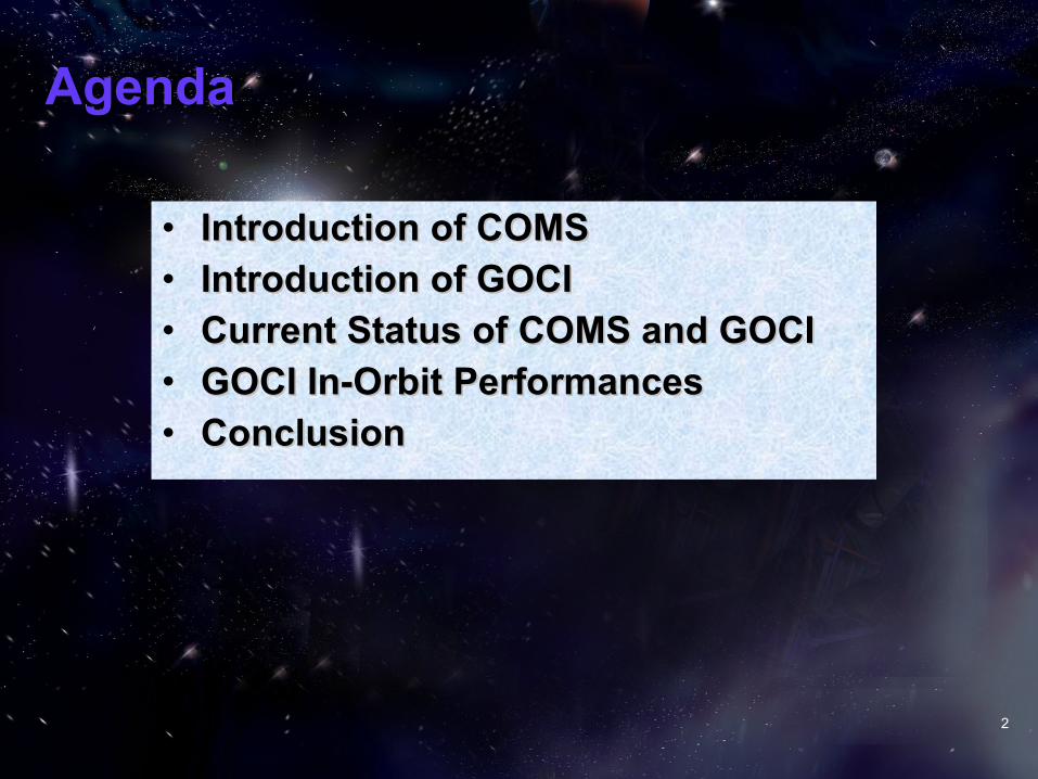
Introduction of COMS (1)Introduction of COMS (1)COMS: Communication, Ocean and Meteorological SatelliteGeostationary satellite Mass at Launch: 2460 kg Orbital Location: 128.2oE Design Life time: 10 years Operational Life: 7.7 years Launch: June 26, 2910, 21:41 (UTC) Launcher: Ariane 5 ECA
COMS Missions A meteo mission (MI)* An ocean imager mission (GOCI)** An experimental Ka band telecommunication mission
* MI: Meteorological Imager ** GOCI: Geostationary Ocean Color Imager
3

Introduction of COMS (2)Introduction of COMS (2)
The main characteristics of COMS- Operational lifetime: 7.7 years- Design lifetime: 10 years - Orbital position: 128.2°E- Launch mass: 2460 Kg- Payload mass: 316 Kg- Payload power: 1077 W- Power generation: 2396 W by GaAs cells solar array- Pointing performance: * better than +/- 0.05°absolute pointing error in roll and pitch for MI/GOCI * better than 0,11°(half cone) error for Ka band RF beam pointing * pointing stability; 10µrad (N/S and E/W) peak to peak over 8s period 55µrad (N/S and E/W) peak to peak over 120s period
4
Introduction of GOCI (1)Introduction of GOCI (1)
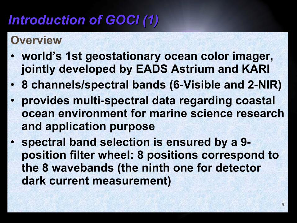
Overview• world’s 1st geostationary ocean color imager,
jointly developed by EADS Astrium and KARI • 8 channels/spectral bands (6-Visible and 2-NIR) • provides multi-spectral data regarding coastal
ocean environment for marine science research and application purpose
• spectral band selection is ensured by a 9-position filter wheel: 8 positions correspond to the 8 wavebands (the ninth one for detector dark current measurement)
5
Introduction of GOCI (2)Introduction of GOCI (2)
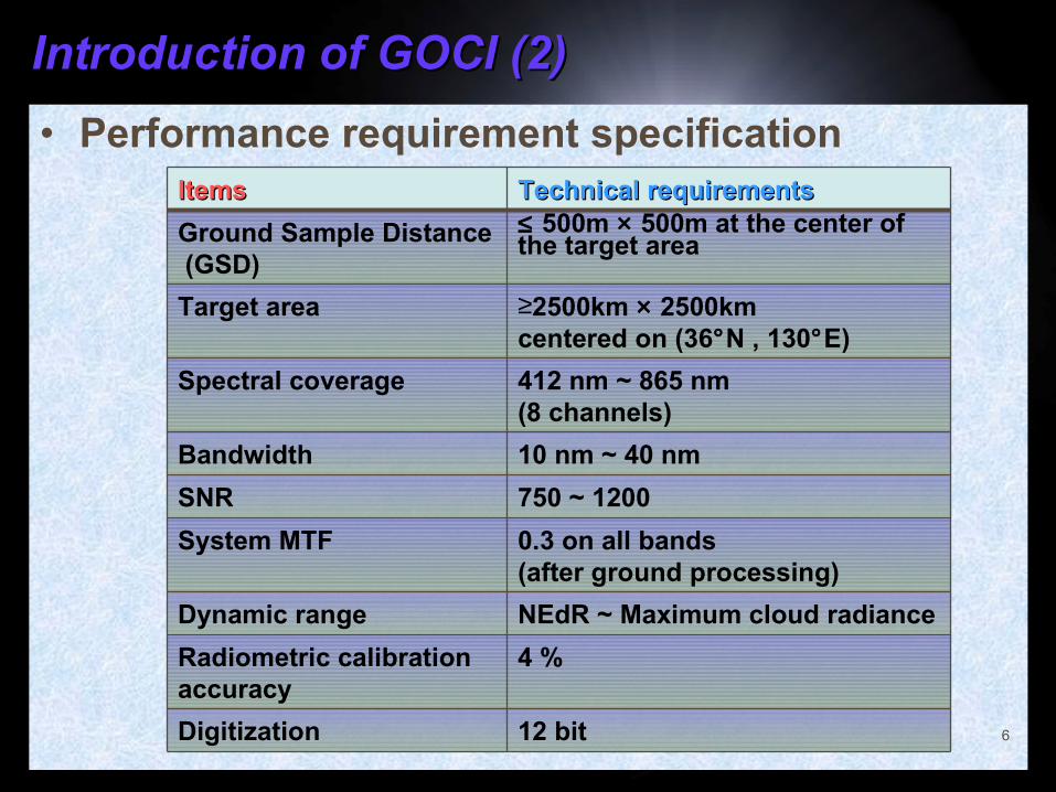
• Performance requirement specification
6
ItemsItems Technical requirementsTechnical requirements
Ground Sample Distance (GSD)
≤ 500m × 500m at the center of the target area
Target area ≥2500km × 2500km centered on (36°N , 130°E)
Spectral coverage 412 nm ~ 865 nm (8 channels)
Bandwidth 10 nm ~ 40 nm
SNR 750 ~ 1200
System MTF 0.3 on all bands (after ground processing)
Dynamic range NEdR ~ Maximum cloud radiance
Radiometric calibration accuracy
4 %
Digitization 12 bit
Introduction of GOCI (3)Introduction of GOCI (3)
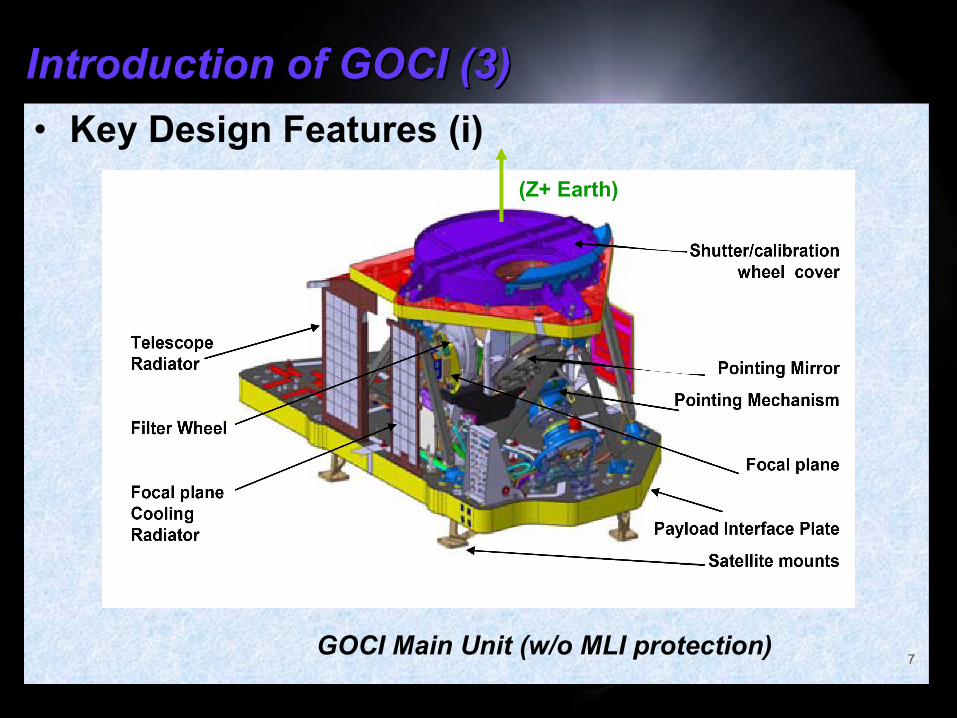
• Key Design Features (i)
7
(Z+ Earth)
GOCI Main Unit (w/o MLI protection)
Introduction of GOCI (4)Introduction of GOCI (4)
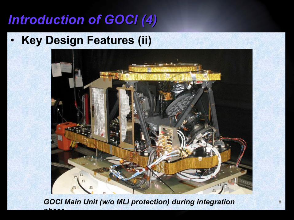
• Key Design Features (ii)
8GOCI Main Unit (w/o MLI protection) during integration phase
Introduction of GOCI (5)Introduction of GOCI (5)
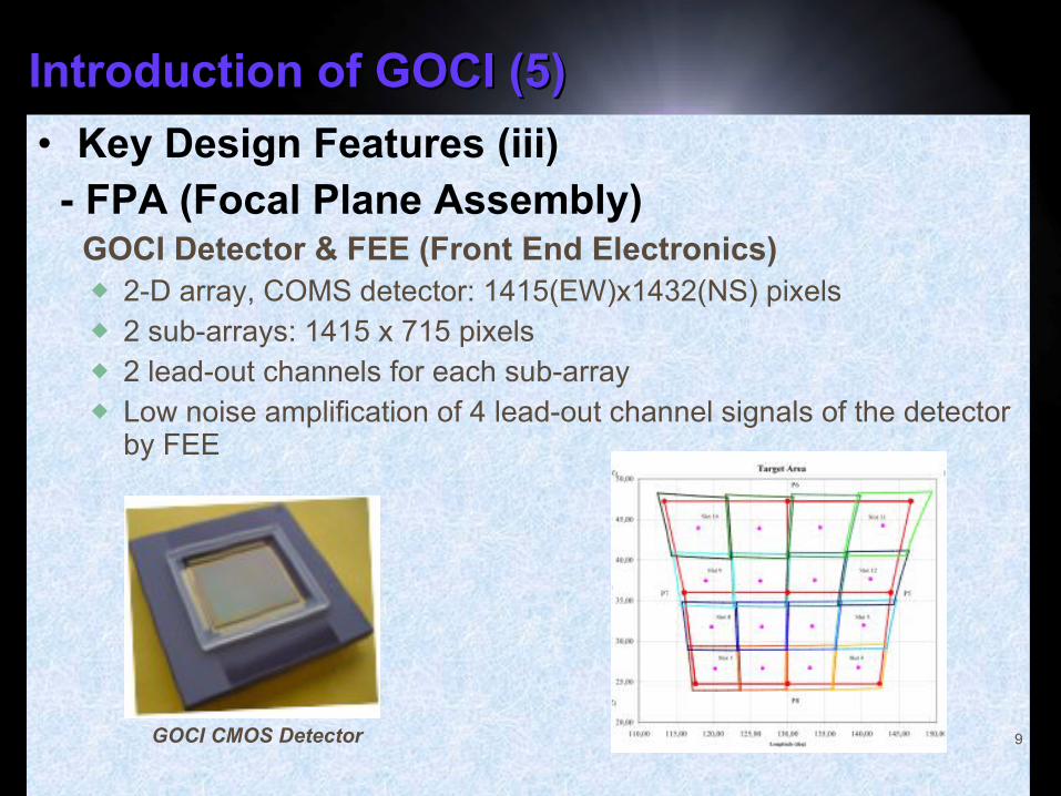
• Key Design Features (iii) - FPA (Focal Plane Assembly) GOCI Detector & FEE (Front End Electronics)
2-D array, COMS detector: 1415(EW)x1432(NS) pixels 2 sub-arrays: 1415 x 715 pixels 2 lead-out channels for each sub-array Low noise amplification of 4 lead-out channel signals of the detector
by FEE
9GOCI CMOS Detector
Introduction of GOCI (5)Introduction of GOCI (5)
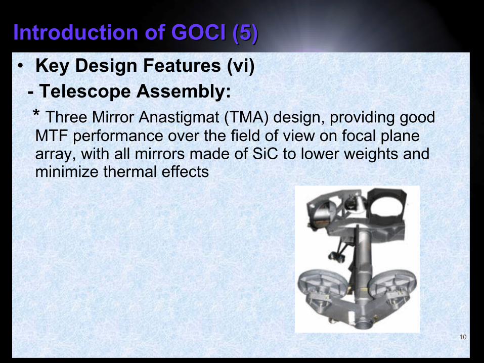
• Key Design Features (vi) - Telescope Assembly: * Three Mirror Anastigmat (TMA) design, providing good
MTF performance over the field of view on focal plane array, with all mirrors made of SiC to lower weights and minimize thermal effects
10
Introduction of GOCI (5)Introduction of GOCI (5)
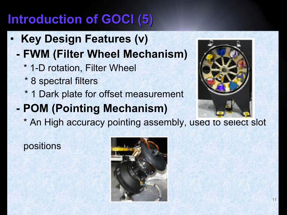
• Key Design Features (v) - FWM (Filter Wheel Mechanism) * 1-D rotation, Filter Wheel
* 8 spectral filters* 1 Dark plate for offset measurement
- POM (Pointing Mechanism) * An High accuracy pointing assembly, used to select slot
positions
11
Introduction of GOCI (6)Introduction of GOCI (6)
• Key Design Features (vi) - SCM (Shutter & Calibration Mechanism) Shutter wheel (1-D rotation)
* For the earth view when opening and for closing instrument cavity when it is inactive
* SD (Solar Diffuser): for the sun view. effectively insensitive to radiation degradation over mission life time (made of Quasi Volumic Diffuser (QVD)).
* DAMD (Diffuser Aging Monitoring Device): for the sun view. a smaller aperture diffuser using identical material to SD, to be used infrequently and suffer virtually no degradation, which allows maintaining the calibration accuracy.
12

Current Status of COMS & GOCI (1)Current Status of COMS & GOCI (1)
COMS launch and mission timeline
13
Current Status of COMS and GOCI (2)Current Status of COMS and GOCI (2)
COMS lOT Summary (July 2010~ Feb 2011)• Bus IOT - All functional checks are completed and Bus is in good health. - Performance checks are completed and subsystems are showing excellent performances.• Payload IOT - All functional checks are completed and all three payloads are in good health. - Radiometric performance checks and radiometric calibration have been completed. - Geometric calibration has been completed with the focus on INR tuning.
14
Current Status of COMS and GOCI (3)Current Status of COMS and GOCI (3)
GOCI Status Summary• Normal Operation for the service to the end user has set forth at the completion of IOT (FAR), from April 2011.• Current GOCI Status - GOCI is in good health with all functions in good check. - Radiometric calibration is exhibiting good trace of performance, calibration and stability. - Geometric correction is exhibiting good landmark matching and excellent INR performance metric.
15

GOCI In-Orbit Performances (1)GOCI In-Orbit Performances (1)
Functional chain architecture of Data Processing
16

GOCI In-Orbit Performances (2)GOCI In-Orbit Performances (2)
Radiometric Performances (1)• Radiance Response
17
FOTLTbLTGS +×+××+××= int3
intint )()(S: Output (Digital count), L: Incident RadianceG: Linear gain, b: Nonlinear gain, Tint: integration timeO: Dark current offset parameter, F: Fixed offset parameter
GOCI radiometric model has been validated through ground test
2D mapping parameter O 2D mapping parameter F
In orbit offset parameter ≈ Ground offset parameter
GOCI In-Orbit Performances (3)GOCI In-Orbit Performances (3)
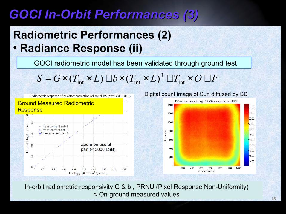
Radiometric Performances (2)• Radiance Response (ii)
18
FOTLTbLTGS +×+××+××= int3
intint )()(
GOCI radiometric model has been validated through ground test
Ground Measured Radiometric Response
In-orbit radiometric responsivity G & b , PRNU (Pixel Response Non-Uniformity) ≈ On-ground measured values
Digital count image of Sun diffused by SD
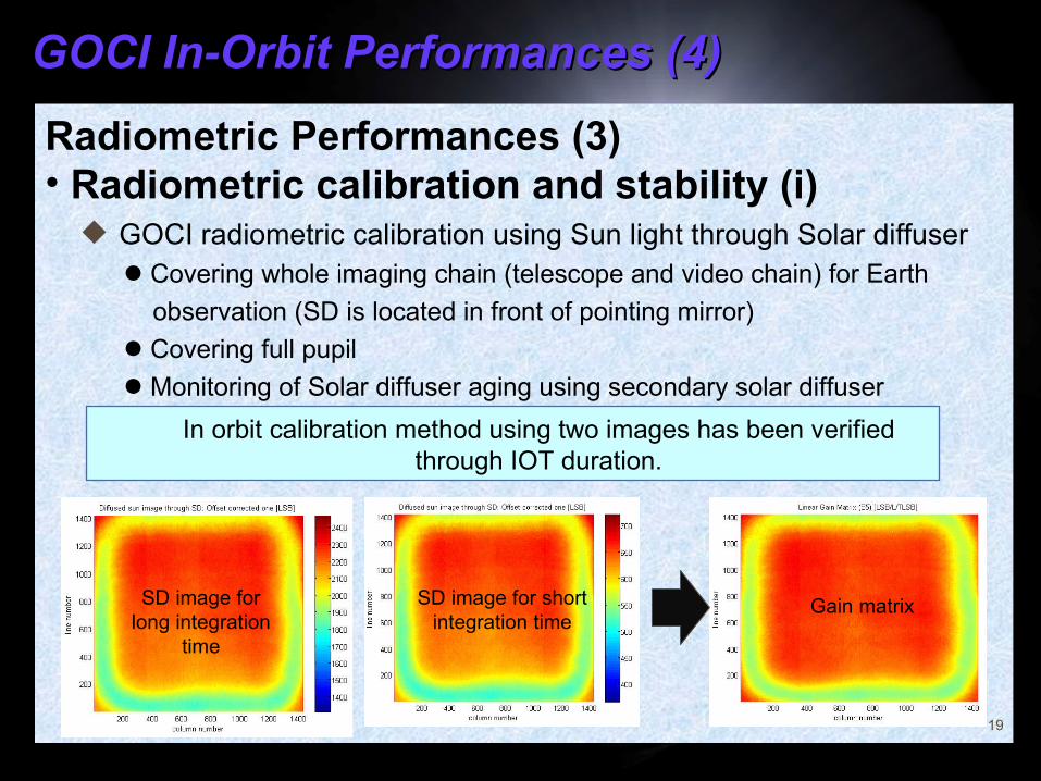
GOCI In-Orbit Performances (4)GOCI In-Orbit Performances (4)
Radiometric Performances (3)• Radiometric calibration and stability (i)
19
GOCI radiometric calibration using Sun light through Solar diffuser Covering whole imaging chain (telescope and video chain) for Earth
observation (SD is located in front of pointing mirror)
Covering full pupil
Monitoring of Solar diffuser aging using secondary solar diffuser
In orbit calibration method using two images has been verified through IOT duration.
SD image forlong integration
time
SD image for short integration time
Gain matrix
GOCI In-Orbit Performances (5)GOCI In-Orbit Performances (5)
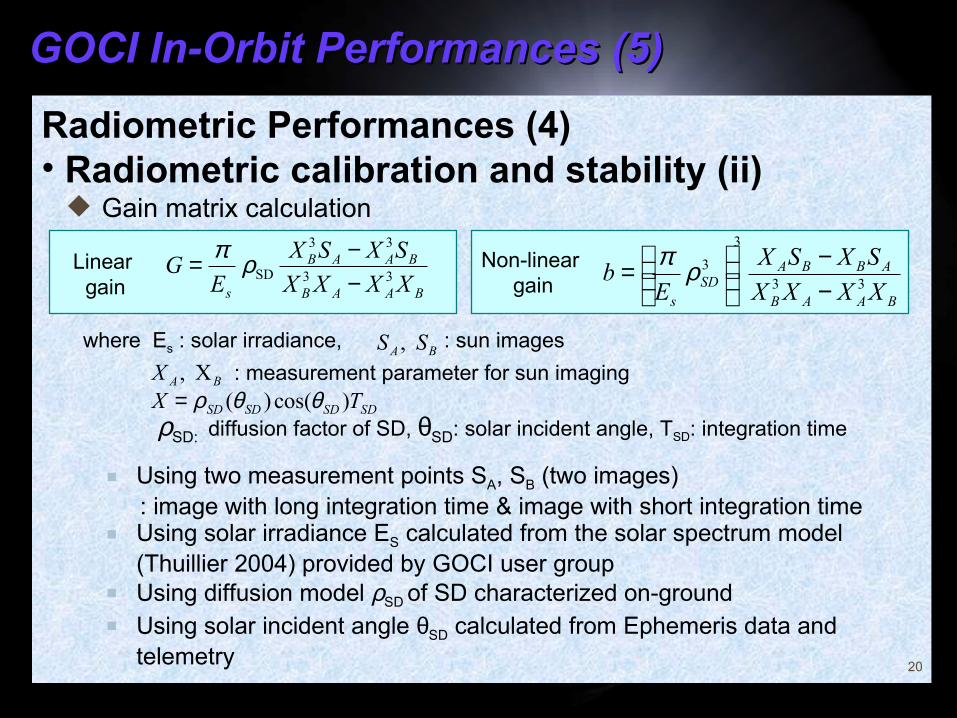
Radiometric Performances (4)• Radiometric calibration and stability (ii)
20
20
Using two measurement points SA, SB (two images) : image with long integration time & image with short integration time Using solar irradiance ES calculated from the solar spectrum model
(Thuillier 2004) provided by GOCI user group Using diffusion model ρSD of SD characterized on-ground Using solar incident angle θSD calculated from Ephemeris data and
telemetry
33
33
SDBAAB
BAAB
s XXXX
SXSX
EG
−−= ρπ
SDSDSDSD TX )cos()( θθρ=
BA SS ,
Linear gain
Non-linear gain
33
3
3
BAAB
ABBASD
s XXXX
SXSX
Eb
−−
= ρπ
: sun images
BAX X , : measurement parameter for sun imaging
ρSD: diffusion factor of SD, θSD: solar incident angle, TSD: integration time
where Es : solar irradiance,
Gain matrix calculation
GOCI In-Orbit Performances (6)GOCI In-Orbit Performances (6)
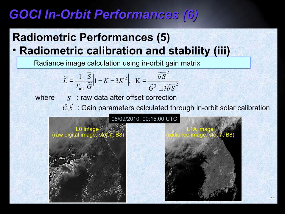
Radiometric Performances (5)• Radiometric calibration and stability (iii)
21
L0 image (raw digital image, slot 7, B8)
L1A image(radiance image, slot 7, B8)
08/09/2010, 00:15:00 UTC
[ ]23
22
int~
3~
~K ,31~
1~
SbG
SbKK
G
S
TL
+=−−=
where : raw data after offset correction
: Gain parameters calculated through in-orbit solar calibrationS
bG~
,~
Radiance image calculation using in-orbit gain matrix
GOCI In-Orbit Performances (7)GOCI In-Orbit Performances (7)
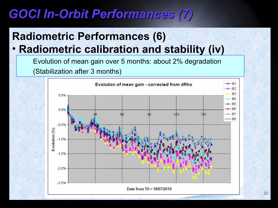
Radiometric Performances (6)• Radiometric calibration and stability (iv)
22
Evolution of mean gain over 5 months: about 2% degradation
(Stabilization after 3 months)
GOCI In-Orbit Performances (8)GOCI In-Orbit Performances (8)
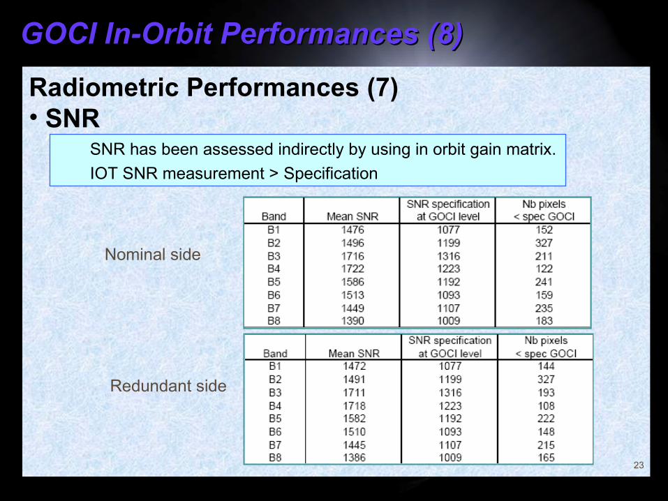
Radiometric Performances (7)• SNR
23
SNR has been assessed indirectly by using in orbit gain matrix.
IOT SNR measurement > Specification
Nominal side
Redundant side
GOCI In-Orbit Performances (9)GOCI In-Orbit Performances (9)
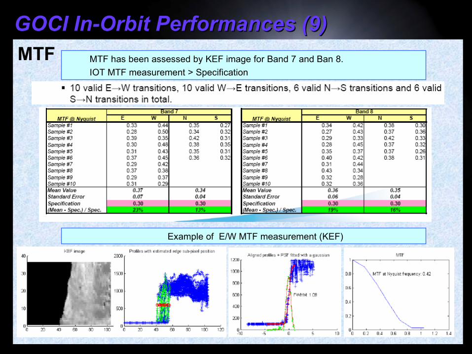
MTF
24
MTF has been assessed by KEF image for Band 7 and Ban 8.
IOT MTF measurement > Specification
Example of E/W MTF measurement (KEF)
GOCI In-Orbit Performances (10)GOCI In-Orbit Performances (10)
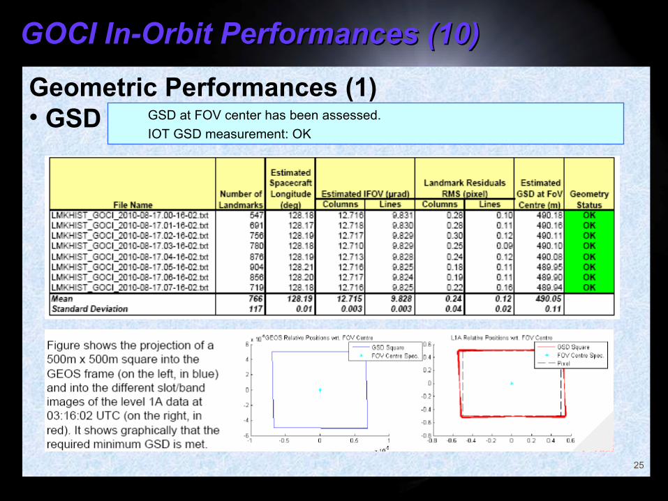
Geometric Performances (1)• GSD
25
GSD at FOV center has been assessed.
IOT GSD measurement: OK
GOCI In-Orbit Performances (11)GOCI In-Orbit Performances (11)
Geometric Performances (2)• Geometric Correction: INR - A new, noble approach to INR system design - Not directly dependent on system and/or payload models and hence can avoid any indispensible modeling and/or prediction error in the process - Acquisition of sufficient number of landmarks in good quality is key to this design - Excellent landmark matching algorithm and the fine-tuning of newly established landmark database with ample landmark sites render such acquisition of sufficient number of good landmarks
26
GOCI In-Orbit Performances (12)GOCI In-Orbit Performances (12)
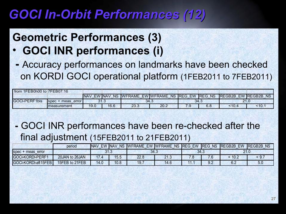
Geometric Performances (3)• GOCI INR performances (i) - Accuracy performances on landmarks have been checked on KORDI GOCI operational platform (1FEB2011 to 7FEB2011)
- GOCI INR performances have been re-checked after the final adjustment (15FEB2011 to 21FEB2011)
27
from 1FEB0h00 to 7FEB07:16NAV_EW NAV_NS WFRAME_EW WFRAME_NS REG_EW REG_NS REGB2B_EW REGB2B_NS
GOCI-PERF1bis spec + meas_errormeasurement 19.0 16.6 23.3 20.2 7.9 6.8 <10.4 <10.1
31.3 34.3 34.3 21.0
period NAV_EW NAV_NS WFRAME_EW WFRAME_NS REG_EW REG_NS REGB2B_EW REGB2B_NS nb_LMKsspec + meas_errorGOCI-KORDI-PERF1 20JAN to 26JAN 17.4 15.5 22.8 21.3 7.8 7.6 < 10.2 < 9.7 14406GOCI-KORDI-aft15FEB 15FEB to 21FEB 14.0 10.8 19.7 14.6 11.1 9.2 6.2 5.0 42927
31.3 34.3 34.3 21.0
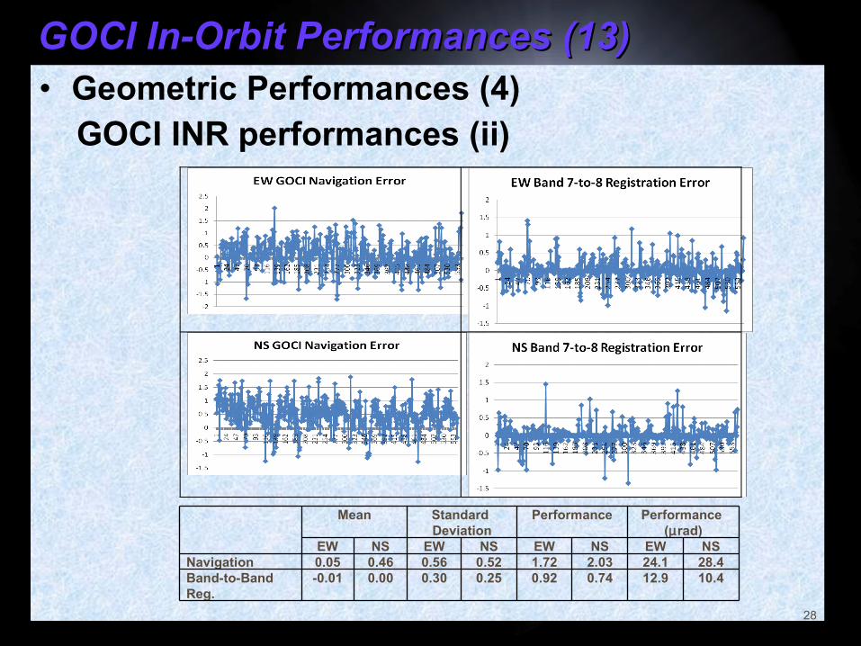
GOCI In-Orbit Performances (13)GOCI In-Orbit Performances (13)• Geometric Performances (4) GOCI INR performances (ii)
28
Mean Standard
DeviationPerformance Performance
(µrad)EW NS EW NS EW NS EW NS
Navigation 0.05 0.46 0.56 0.52 1.72 2.03 24.1 28.4Band-to-Band Reg.
-0.01 0.00 0.30 0.25 0.92 0.74 12.9 10.4
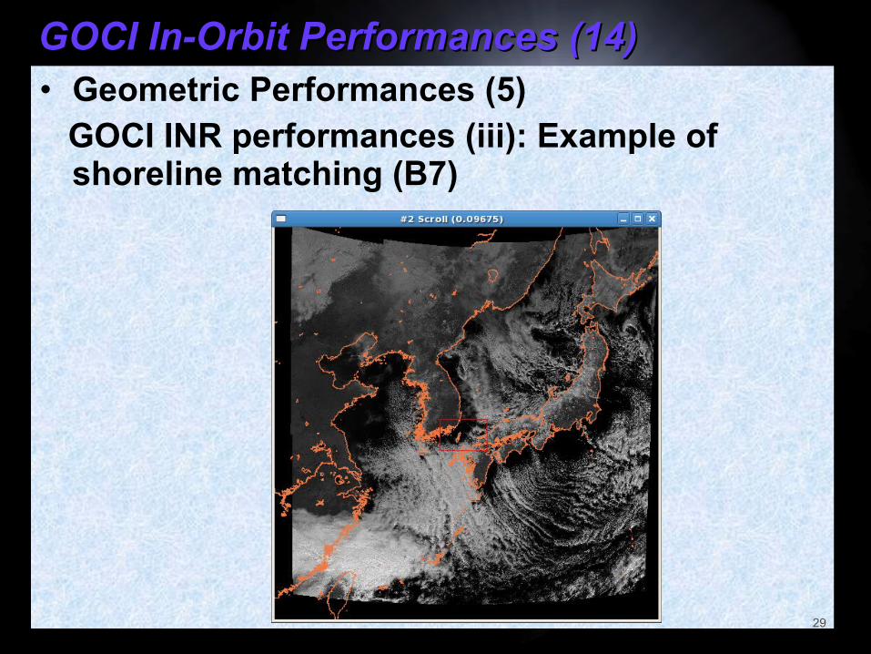
GOCI In-Orbit Performances (14)GOCI In-Orbit Performances (14)• Geometric Performances (5) GOCI INR performances (iii): Example of
shoreline matching (B7)
29
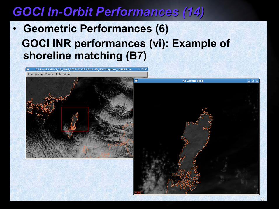
GOCI In-Orbit Performances (14)GOCI In-Orbit Performances (14)• Geometric Performances (6) GOCI INR performances (vi): Example of
shoreline matching (B7)
30
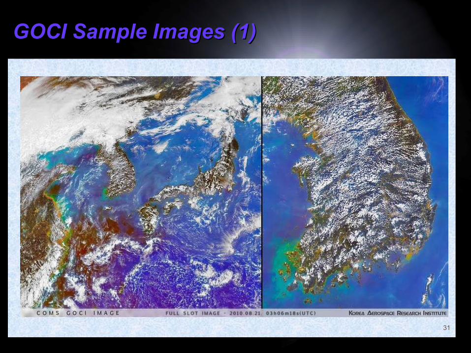
GOCI Sample Images (1)GOCI Sample Images (1)
31

GOCI Sample Images (2)GOCI Sample Images (2)
32
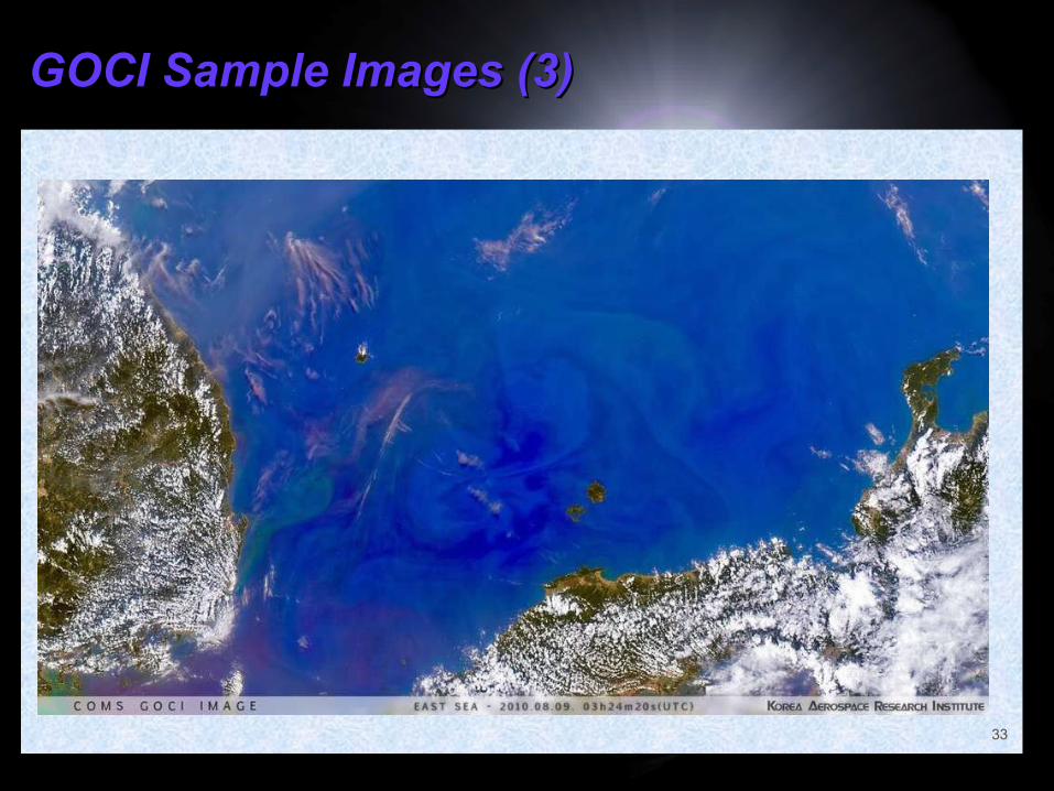
GOCI Sample Images (3)GOCI Sample Images (3)
33
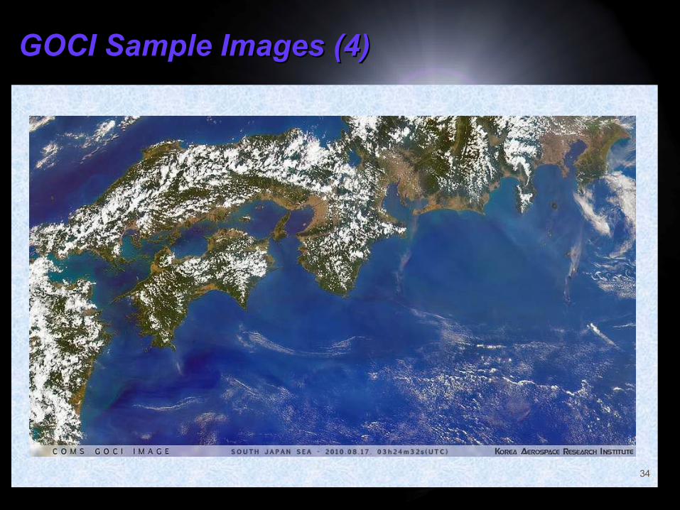
GOCI Sample Images (4)GOCI Sample Images (4)
34
ConclusionConclusion• The newly developed GOCI is demonstrating quite
decent performances in orbit, both in radiometric and geometric aspects.
• It is anticipated that such GOCI image data will bring a new dimension to the geostationary remote sensing and in the related scientific research fields.
• More in-depth review, thorough analysis and active iteration are desired to define the requirement specification for the next generation GOCI (‘GOCI-2’).
• It is hoped that GOCI will further be expanded in terms of its design, development, operation and applications, into the next generation of geostationary remote sensing satellites.
35