Embed Size (px)
Citation preview

Fundamentals of Database systems
Ministry of Higher EducationBamyan University
Computer Science Department
1
Presented by : Mustafa Kamel MohammadiEmail : [email protected]
Data Modeling Using the Entity-Relationship (ER) ModelFundamentals of database system 6th edition

Learning objective In this chapter you will learn
Relational data model concepts What is entity? What is attribute and it’s types What is relationship? What is an Entity-Relationship data model? Relational data model constraints Characteristics of relation
2
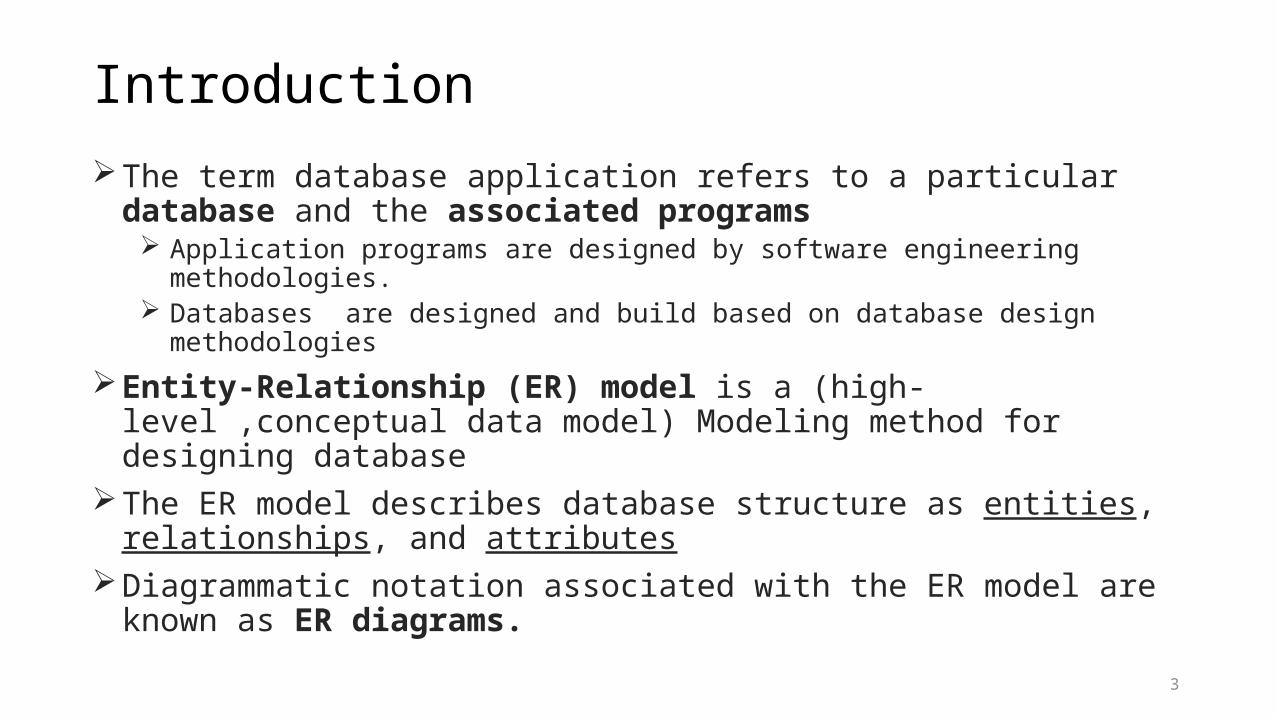
IntroductionThe term database application refers to a particular database and the associated
programs Application programs are designed by software engineering methodologies. Databases are designed and build based on database design methodologies
Entity-Relationship (ER) model is a (high-level ,conceptual data model) Modeling method for designing database
The ER model describes database structure as entities, relationships, and attributes
Diagrammatic notation associated with the ER model are known as ER diagrams.
3
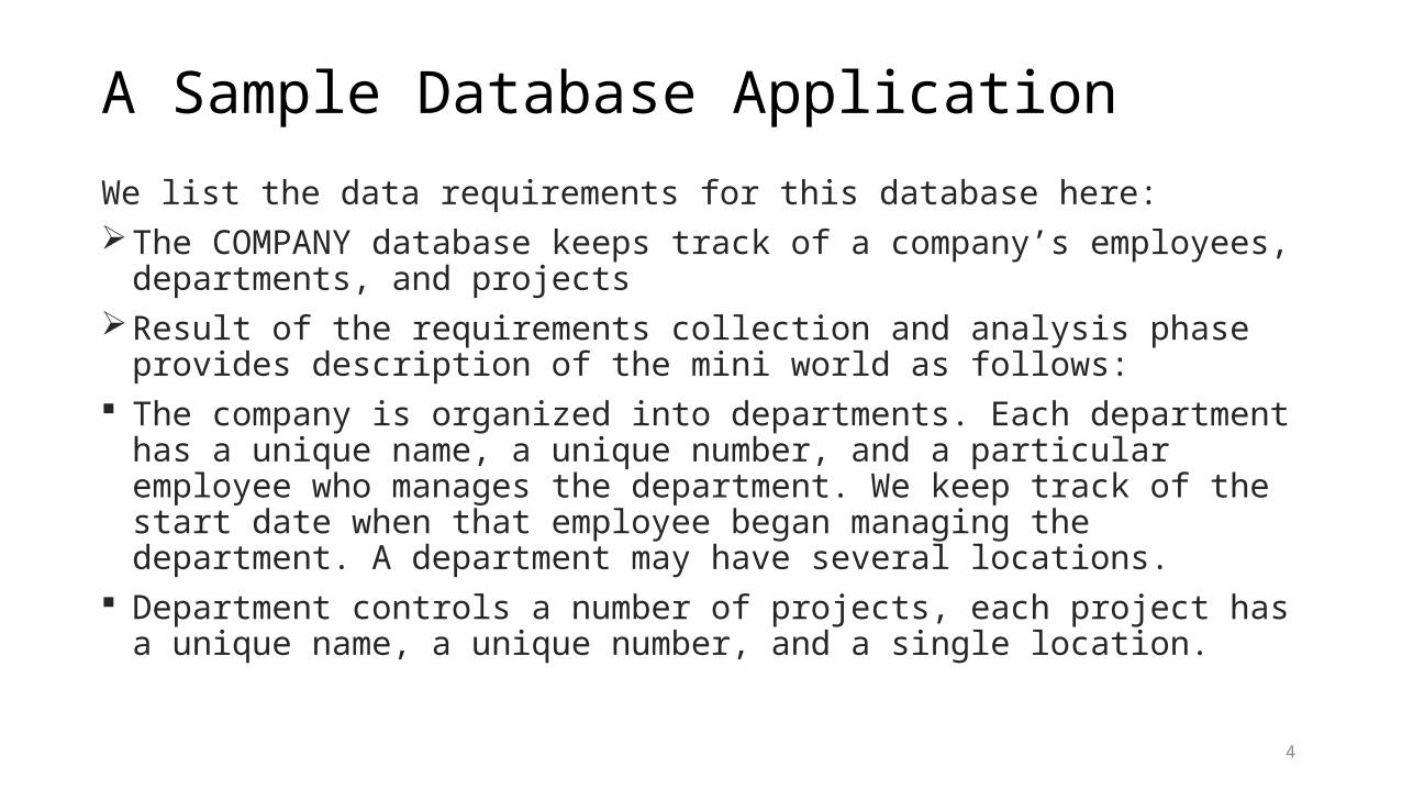
A Sample Database ApplicationWe list the data requirements for this database here:The COMPANY database keeps track of a company’s employees, departments,
and projectsResult of the requirements collection and analysis phase provides description of
the mini world as follows: The company is organized into departments. Each department has a unique
name, a unique number, and a particular employee who manages the department. We keep track of the start date when that employee began managing the department. A department may have several locations.
Department controls a number of projects, each project has a unique name, a unique number, and a single location.
4
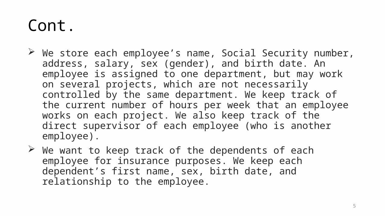
Cont. We store each employee’s name, Social Security number, address, salary, sex
(gender), and birth date. An employee is assigned to one department, but may work on several projects, which are not necessarily controlled by the same department. We keep track of the current number of hours per week that an employee works on each project. We also keep track of the direct supervisor of each employee (who is another employee).
We want to keep track of the dependents of each employee for insurance purposes. We keep each dependent’s first name, sex, birth date, and relationship to the employee.
5
EntityThe basic object that the ER model represents is an entity, which is a thing in the
real world with an independent existence may be an object with a physical existence (for example, a particular person, car, house, or
employee) it may be an object with a conceptual existence (for instance, a company, a job, or a
university course). Each entity has attributes the particular properties that describe it.
For example, an EMPLOYEE entity may be described by the employee’s name, age, address, salary, and job
An entity will have value for each of its attributes. The attribute values that describe each entity become a major part of the data stored in the
database.
6

7
What is expected after learning ER modeling

8
Entity values stored in database

Types of attribute Simple and composite attributes Single valued and multivalued attributes Stored and derived attributes
Composite versus Simple (Atomic) Attributes.Attributes that are not divisible are called simple or atomic attributes.Composite attributes can be divided into smaller subparts, which represent more
basic attributes with independent meanings. For example, the Address attribute of the EMPLOYEE can be subdivided into State, City,
Street, and Zip Composite attributes can form a hierarchy like street can be further divided to : Number,
Street, and Apartment_number
9
Cont. If the composite attribute is referenced only as a whole Then the whole composite attribute
can be designated as a simple attribute. If we are interested sometimes to some attributes so we need to subdivide them into smaller
attributes.
Single-Valued versus Multivalued AttributesMost attributes have a single value for a particular entity, such attributes are
called single-valued For example, Age is a single-valued attribute of a person
In some cases an attribute can have a set of values for the same entity, so these are called Multivalued Attributes A Colors attribute for a car, or a College_degrees attribute for a person A multivalued attribute may have lower and upper bounds to constrain the number of values
allowed for each individual entity
10

Cont.Stored versus Derived AttributesStored attribute are those which are actually stored within database like
birth_dateDerived attributes are those which are derived from the values of either
Stored attribute like birth_date Whole relation like count_of_employees
Complex Attributes In general, composite and multivalued attributes can be nested. Such attributes are called complex attributes. For example, if a person can have more than one residence and each residence
can have a single address and a phones
11
NULL value If it is inapplicable value for an attribute
The college_degree for illiterate persons Passport_number for those who do not have passport
Unknown like Home_phone attribute of a person is NULLKnown but missing like Height attribute of a person is listed as NULL
12
Entity Types, Entity Sets, Keys, and Value SetsEntity Types and Entity SetsEntity type defines a collection of entities that have the same attributes. Each entity
type in the database is described by its name and attributesThe collection of all entities of a particular entity type in the database at any point in
time is called an Entity setThe entity set is usually referred to the same name as the entity type.For example, EMPLOYEE refers to both a type of entity as well as the current set of all
employee entities in the databaseAn entity type is represented in ER diagrams as a rectangular box enclosing the entity
type name.Attribute names are enclosed in ovals and are attached to their entity type by straight
lines Composite attributes are attached to their component attributes by straight lines Multivalued attributes are displayed in double ovals
13
14
Cont.Key Attributes of an Entity TypeAn important constraint on the entities of an entity type is the key or uniqueness
constraint on attributes.An attributes whose values are distinct for each individual entity in the entity set
is called a key attribute For example, the Name attribute is a key of the COMPANY entity type ID number is the key in students entity type.
Sometimes several attributes together form a key, meaning that the combination of the attribute values must be distinct for each entity Define a composite attribute and designate it as a key attribute of the entity type.
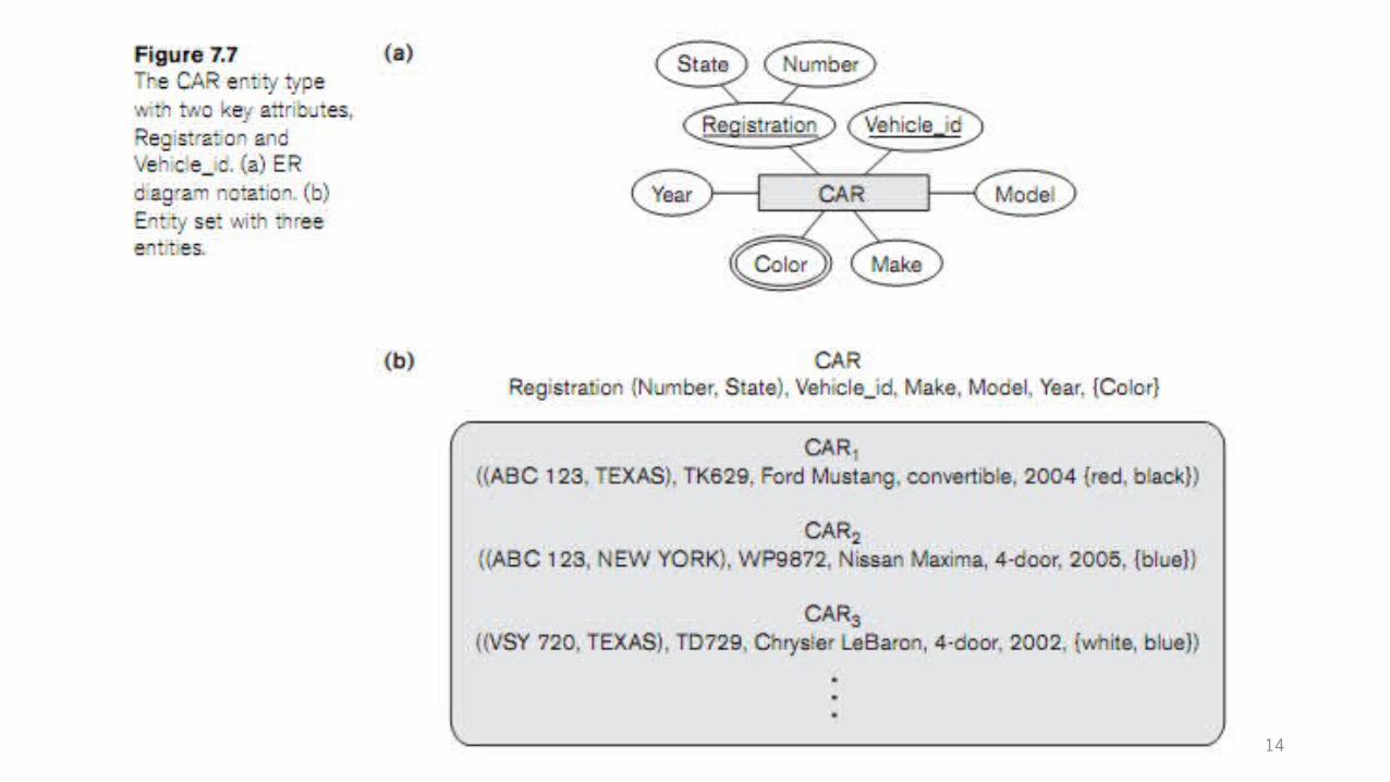
Some entity types have more than one key attribute. For example, each of the Vehicle_id and Registration attributes of the entity type CAR
Each key attribute has its name underlined inside the oval.15

Cont.Value Set (Domain) of Attribute. Each simple attribute of an entity type is associated with a value set (or domain
of values), which specifies the set of values that may be assigned to that attribute for each individual entity. we can specify the value set of the Age attribute of EMPLOYEE to be the set of integer
numbers between 16 and 70A NULL value is represented by the empty set. For single-valued attributes
16

17
In this primary design we have not include the relationships between entities yet.
Relationship Types ,Relationship Sets ,Roles and Structural ConstraintsThere are several implicit relationships among the various entity types. In fact, whenever an attribute of one entity type refers to another entity type,
some relationship exists. For example, the attribute Manager of DEPARTMENT refers to an employee who manages
the department The attribute Controlling_department of PROJECT refers to the department that controls the
project In the ER model, these references should not be represented as attributes but as
relationships In the initial design of entity types, relationships are typically captured in the
form of attributes. As the design is refined, these attributes get converted into relationships between entity types.
18
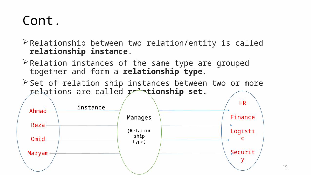
Cont.Relationship between two relation/entity is called relationship instance.Relation instances of the same type are grouped together and form a
relationship type. Set of relation ship instances between two or more relations are called
relationship set.
19
Ahmad
Reza
Omid
Maryam
HR
Finance
Logistic
Security
Manages
(Relationship type)
instance
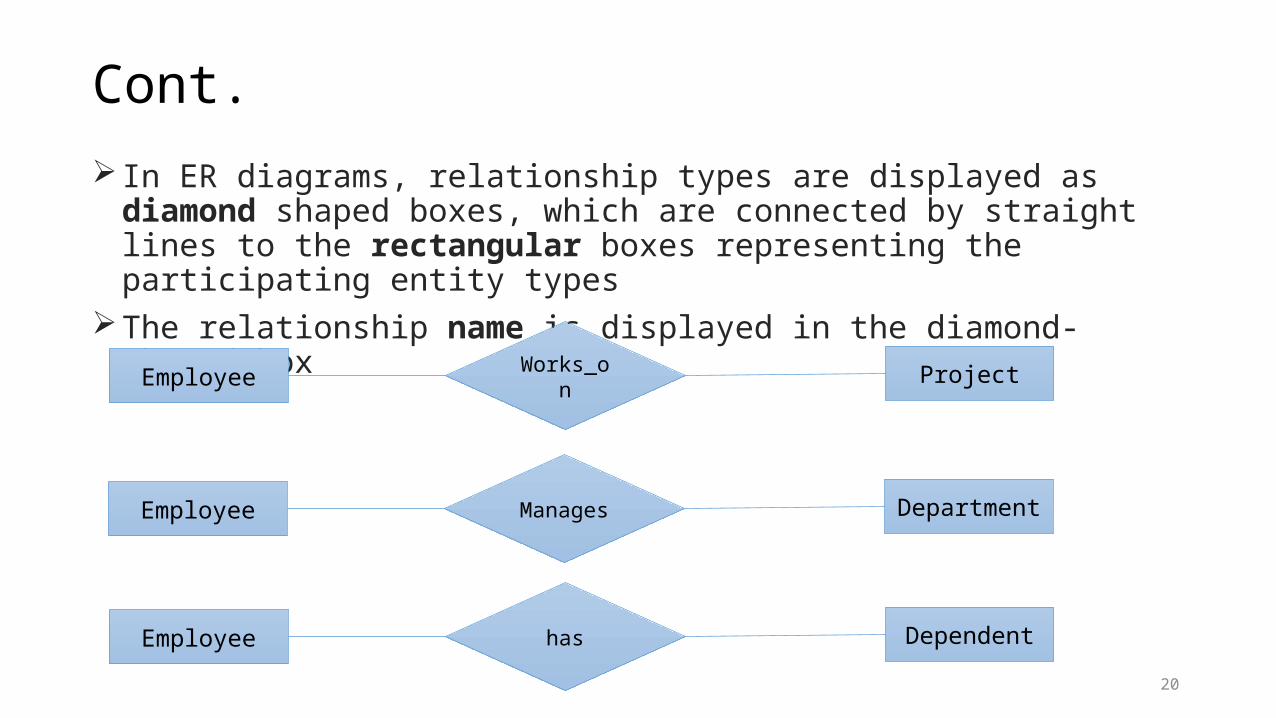
Cont. In ER diagrams, relationship types are displayed as diamond shaped boxes, which
are connected by straight lines to the rectangular boxes representing the participating entity types
The relationship name is displayed in the diamond-shaped box
20
Employee Dependenthas
Employee ProjectWorks_on
Employee DepartmentManages
Cont.
21
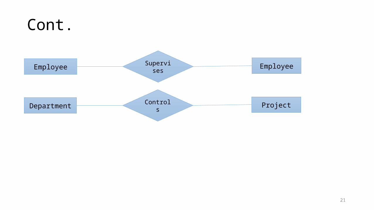
Employee EmployeeSupervises
Department ProjectControls
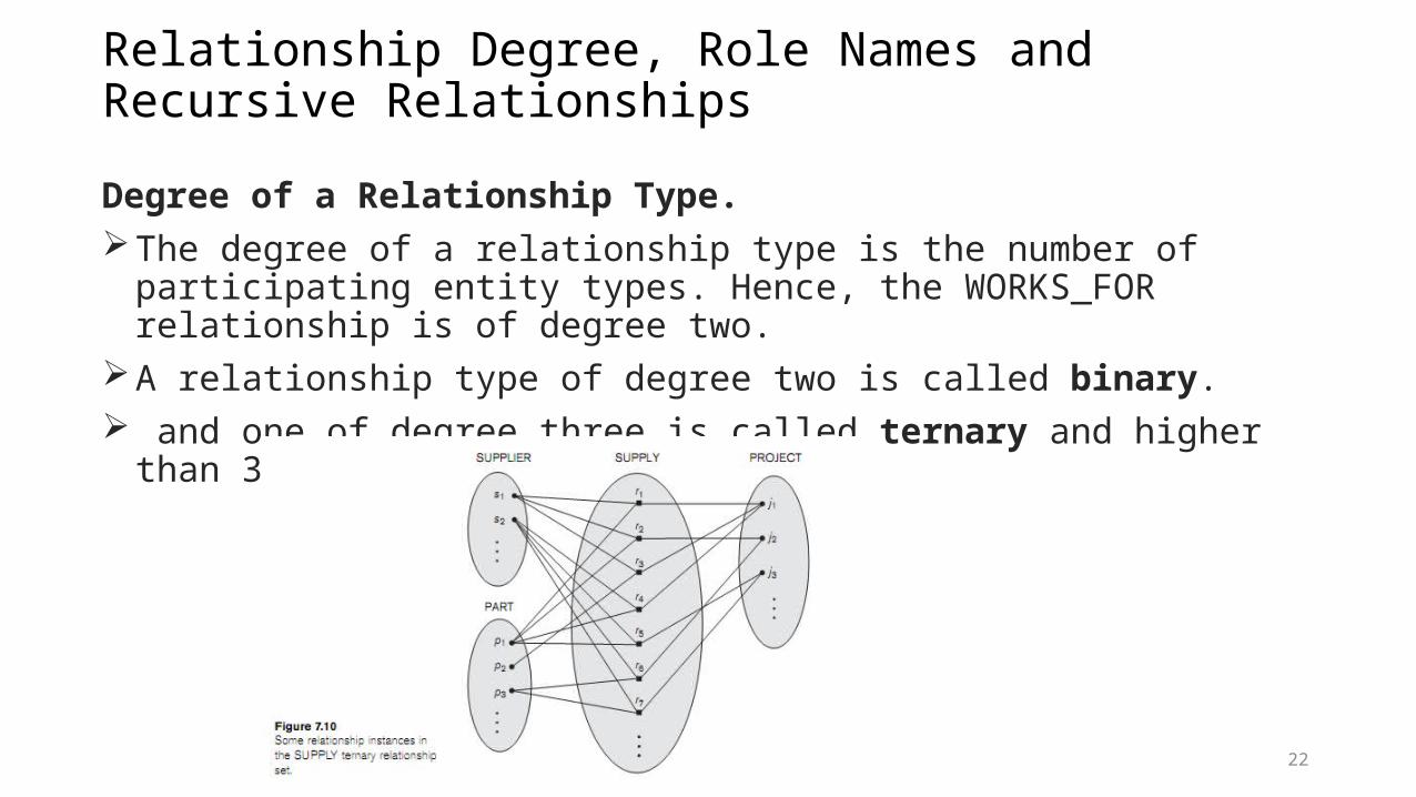
Relationship Degree, Role Names and Recursive RelationshipsDegree of a Relationship Type. The degree of a relationship type is the number of participating entity types.
Hence, the WORKS_FOR relationship is of degree two.A relationship type of degree two is called binary. and one of degree three is called ternary and higher than 3 are n-ary
22
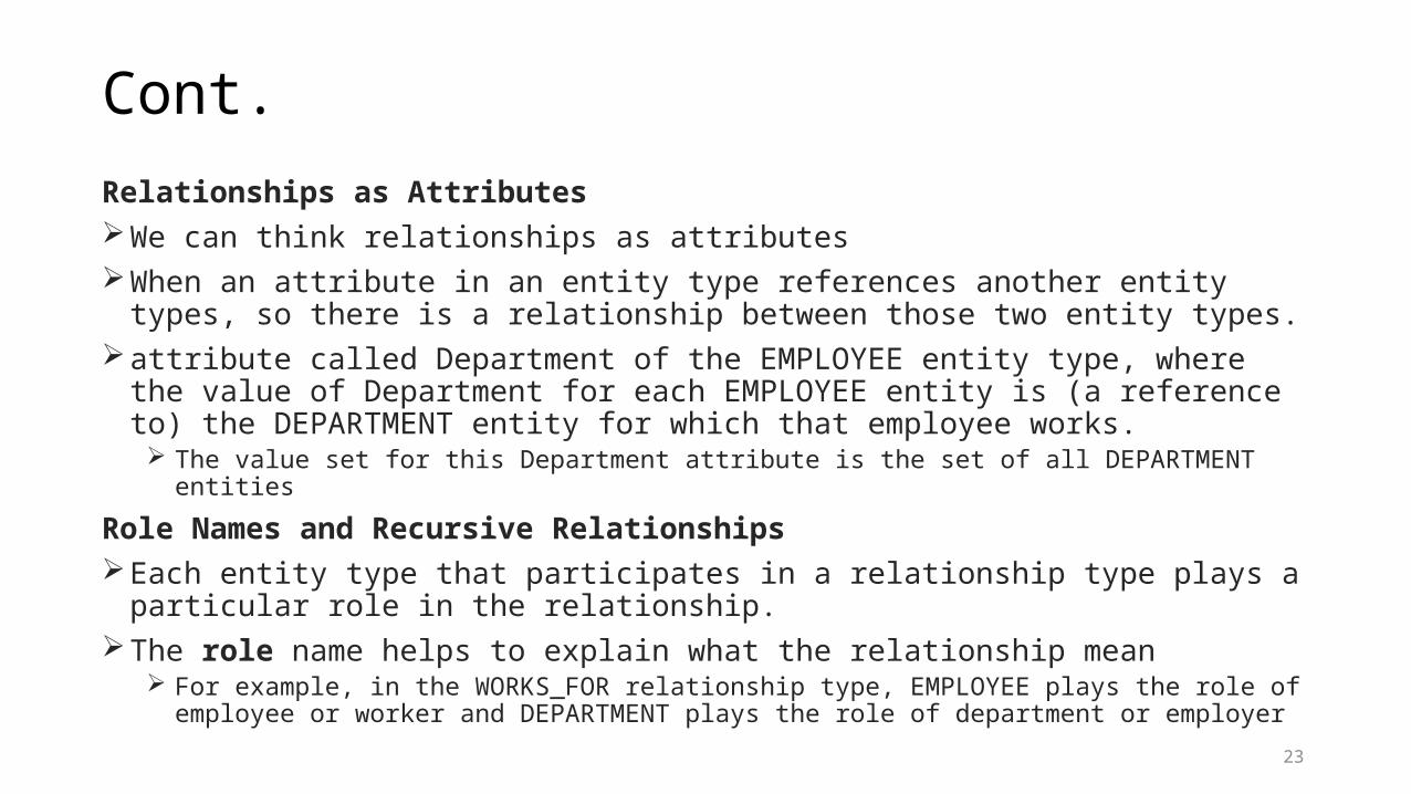
Cont.Relationships as AttributesWe can think relationships as attributesWhen an attribute in an entity type references another entity types, so there is a
relationship between those two entity types. attribute called Department of the EMPLOYEE entity type, where the value of
Department for each EMPLOYEE entity is (a reference to) the DEPARTMENT entity for which that employee works. The value set for this Department attribute is the set of all DEPARTMENT entities
Role Names and Recursive RelationshipsEach entity type that participates in a relationship type plays a particular role in the
relationship.The role name helps to explain what the relationship mean
For example, in the WORKS_FOR relationship type, EMPLOYEE plays the role of employee or worker and DEPARTMENT plays the role of department or employer
23

Cont.Role names are clear when the participating entities are distinct. In some cases the same entity type participates more than once in a relationship
type in different roles. Such relationship types are called recursive relationships In such cases the role name becomes essential for distinguishing the meaning of
the role that each participating entity plays.The SUPERVISION relationship type relates an employee to a supervisor, where
both employee and supervisor entities are members of the same EMPLOYEE entity set
EMPLOYEE entity type participates twice in SUPERVISION once in the role of supervisor (or boss), and once in the role of supervisee (or subordinate)
24
Constraints on relationship types Relationship types usually have certain constraints that limit the possible combinations
of entities that may participate in the corresponding relationship set. These constraints are determined from the mini world situation that the relationships
represent For example, the company has a rule that each employee must work for exactly one department
1. Cardinality Ratios for Binary Relationships The cardinality ratio for a binary relationship specifies the maximum number of
relationship instances that an entity can participate in. For example, in the WORKS_FOR binary relationship type DEPARTMENT, EMPLOYEE is of
cardinality ratio 1:N,meaning that each department can be related to (that is, employs) any number of employees.
(N indicates there is no maximum number). On the other hand, an employee can be related to a maximum of one department. The
possible cardinality ratios for binary relationship types are 1:1, 1:N, N:1, and M:N.25
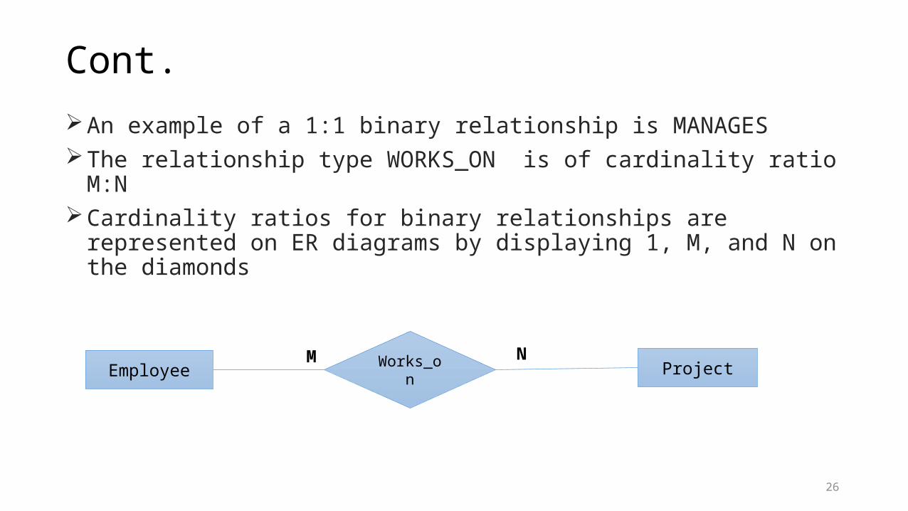
Cont.An example of a 1:1 binary relationship is MANAGESThe relationship type WORKS_ON is of cardinality ratio M:NCardinality ratios for binary relationships are represented on ER diagrams by
displaying 1, M, and N on the diamonds
26
Employee ProjectWorks_onM N

27
Cont.2. Participation Constraints or (Existence Dependencies)The participation constraint specifies whether the existence of an entity in a
relationship is a must or not.This constraint specifies the minimum number of relationship instances that each
entity can participate in, and is sometimes called the minimum cardinality constraintThere are two types of participation constraints total and partialTotal participation or existence dependency, meaning that every entity must
participate at that relationship If a company policy states that every employee must work for a department, then participation of
an employee entity in WORKS_FOR relationship is Total.Partial means that every entity may or may not participate in a relationship.
An employee may or may not manage a department. It is not a must for an employee to manage department.
28
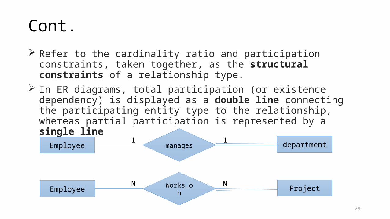
Cont. Refer to the cardinality ratio and participation constraints, taken together, as the
structural constraints of a relationship type. In ER diagrams, total participation (or existence dependency) is displayed as a
double line connecting the participating entity type to the relationship, whereas partial participation is represented by a single line
29
Employee ProjectWorks_onN M
Employee department1 1manages
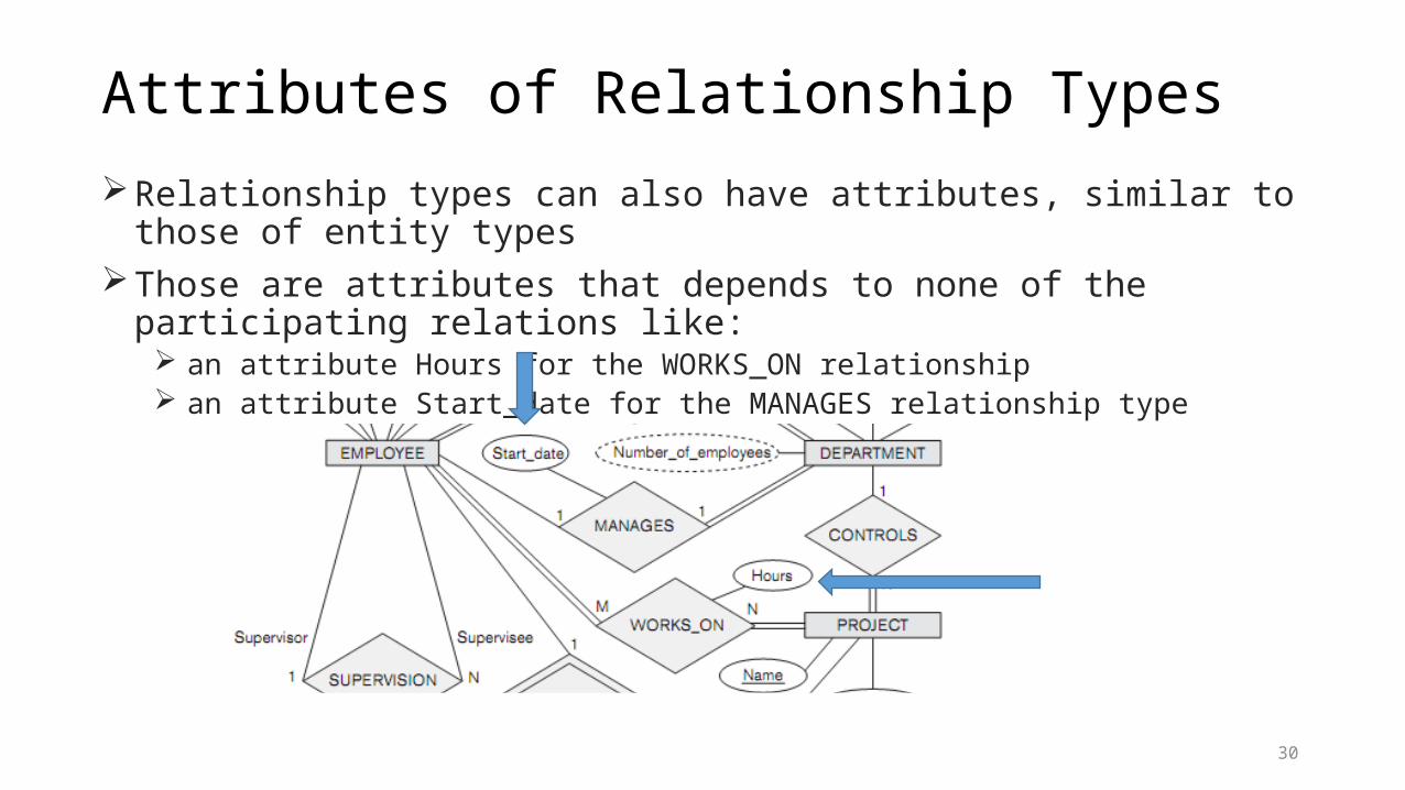
Attributes of Relationship TypesRelationship types can also have attributes, similar to those of entity typesThose are attributes that depends to none of the participating relations like:
an attribute Hours for the WORKS_ON relationship an attribute Start_date for the MANAGES relationship type
30
Weak Entity TypesEntity types that do not have key attributes of their own are called weak entity types In contrast, regular entity types that do have a key attribute and are so called strong
entity types.Entities belonging to a weak entity type are identified by being related to specific
entities from another entity type in combination with one of their attribute values We call this other entity type the identifying or owner entity type, and we call the relationship
type that relates a weak entity type to its owner the identifying relationshipA weak entity type always has a total participation constraint (existence dependency)
with respect to its identifying relationship because a weak entity cannot be identified without an owner entity
Not every existence dependency results in a weak entity type For example, a DRIVER_LICENSE entity cannot exist unless it is related to a PERSON entity, even
though it has its own key (License_number) and hence is not a weak entity
31

Cont.A weak entity type normally has a partial key, which is the attribute that can uniquely
identify weak entities that are related to the same owner entity In our example, if we assume that no two dependents of the same employee ever
have the same first name, the attribute Name of DEPENDENT is the partial key. In the worst case, a composite attribute of all the weak entity’s attributes will be the partial key
In ER diagrams, both a weak entity type and its identifying relationship are distinguished by surrounding their boxes and diamonds with double lines
The partial key attribute is underlined with a dashed or dotted lineWeak entity types can sometimes be represented as complex (composite,
multivalued) attributesThe choice of which representation to use is made by the database designer
If the weak entity may participate independently in relationship types other than its identifying relationship type, then it should not be modeled as a complex attribute.
32

Refining the ER diagram for COMPANY database We can now refine the database design by changing the attributes that represent
relationships into relationship types The cardinality ratio and participation constraint of each relationship type are
determined from the requirements If some cardinality ratio or dependency cannot be determined from the requirements,
the users must be questioned further to determine these structural constraints. In our example, we specify the following relationship types:
MANAGES, a 1:1 relationship type between EMPLOYEE and DEPARTMENT WORKS_FOR, a 1:N relationship type between DEPARTMENT and EMPLOYEE. CONTROLS, a 1:N relationship type between DEPARTMENT and PROJECT SUPERVISION, a 1:N relationship type between EMPLOYEE (in the supervisor role) and EMPLOYEE
(in the supervisee role) WORKS_ON, determined to be an M:N relationship type with attribute Hours, after the users
indicate that a project can have several employees DEPENDENTS_OF, a 1:N relationship type between EMPLOYEE and DEPENDENT
33

34
Proper naming of SCHEMA constructWe choose to use singular names for entity types, rather than plural ones, because
the entity type name applies to each individual entity belonging to that entity type. In our ER diagrams, we will use the convention
Entity type and relationship type names are uppercase letters Attribute names have their initial letter capitalized Role names are lowercase letters
The nouns appearing in the narrative tend to give rise to entity type names, and the verbs tend to indicate names of relationship types
Attribute names generally arise from additional nouns that describe the nouns corresponding to entity types.
Relationships has this naming conventions Left to right or right to left Bottom to up, up to bottom
35

Design Choices for ER Conceptual DesignDifficult to decide whether a particular concept in the mini world should be modeled as an entity type, an attribute or a relationship type.A concept may be first modeled as an attribute and then refined into a
relationship because it is determined that the attribute is a reference to another entity type Once an attribute is replaced by a relationship, the attribute itself should be removed from
the entity type to avoid duplicationAn attribute that exists in several entity types may be elevated or promoted to an
independent entity type. If an entity type DEPARTMENT exists in the initial design with a single attribute
Dept_name and is related to only one other entity type, STUDENT. In this case, DEPARTMENT may be reduced or demoted to an attribute of STUDENT
36

Alternative notation for ER diagramwe describe one alternative ER notation for specifying structural constraints on
relationships, which replaces the cardinality ratio (1:1, 1:N, M:N) and single/double line notation for participation constraints
This notation involves associating a pair of integer numbers (min, max) with each participation of an entity type E in a relationship type R, where 0 ≤ min ≤ max and max ≥ 1
The numbers mean that for each entity e in E, e must participate in at least min and at most max relationship instances in R at any point in time. In this method,min = 0 implies partial participation, whereas min > 0 implies total participation.
37

38
Example of Other Notation: UML Class DiagramsThe UML methodology is being used extensively in software design and has many
types of diagrams for various software design purposes.We only briefly present the basics of UML class diagrams here, and compare
them with ER diagrams.The entity types are modeled as classes In UML class diagrams, a class (similar to an entity type in ER) is displayed as a
box The top section gives the class name the middle section includes the attributes the last section includes operations that can be applied to individual objects
The designer can optionally specify the domain of an attribute if desired, by placing a colon (:) followed by the domain name
39

40
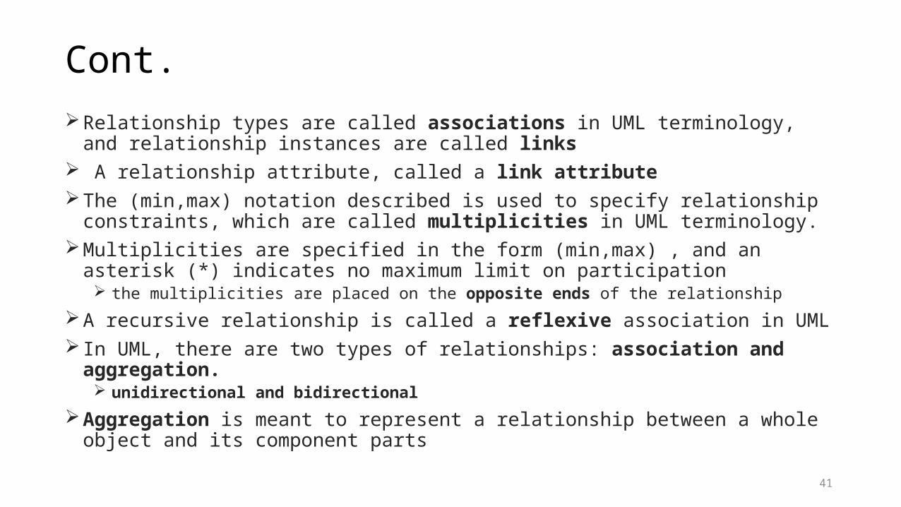
Cont.Relationship types are called associations in UML terminology, and relationship
instances are called links A relationship attribute, called a link attributeThe (min,max) notation described is used to specify relationship constraints, which
are called multiplicities in UML terminology.Multiplicities are specified in the form (min,max) , and an asterisk (*) indicates no
maximum limit on participation the multiplicities are placed on the opposite ends of the relationship
A recursive relationship is called a reflexive association in UML In UML, there are two types of relationships: association and aggregation.
unidirectional and bidirectionalAggregation is meant to represent a relationship between a whole object and its
component parts41
Cont.Weak entities can be modeled using the construct called qualified association (or
qualified aggregation) The partial is called the discriminator in UML terminology
42
43

44