Embed Size (px)
Citation preview

sensors
Article
From Sensor Networks to Internet of Things.Bluetooth Low Energy, a Standard for This Evolution
Diego Hortelano 1,*,†, Teresa Olivares 2,†, M. Carmen Ruiz 2,†, Celia Garrido-Hidalgo 1,†
and Vicente López 1,†
1 Albacete Research Institute of Informatics, University of Castilla-La Mancha, 02071 Albacete, Spain;[email protected] (C.G.-H.); [email protected] (V.L.)
2 Faculty of Computer Science Engineering, University of Castilla-La Mancha, 02071 Albacete, Spain;[email protected] (T.O.); [email protected] (M.C.R.)
* Correspondence: [email protected]; Tel.: +34-967-599-200† These authors contributed equally to this work.
Academic Editor: Gonzalo Pajares MartinsanzReceived: 9 December 2016; Accepted: 3 February 2017; Published: 14 February 2017
Abstract: Current sensor networks need to be improved and updated to satisfy newessential requirements of the Internet of Things, where cutting-edge applications will appear.These requirements are: total coverage, zero fails (high performance), scalability and sustainability(hardware and software). We are going to evaluate Bluetooth Low Energy as wireless transmissiontechnology and as the ideal candidate for these improvements, due to its low power consumption, itslow cost radio chips and its ability to communicate with users directly, using their smartphones orsmartbands. However, this technology is relatively recent, and standard network topologies are notable to fulfil its new requirements. To address these shortcomings, the implementation of other moreflexible topologies (as the mesh topology) will be very interesting. After studying it in depth, we haveidentified certain weaknesses, for example, specific devices are needed to provide network scalability,and the need to choose between high performance or sustainability. In this paper, after presenting thestudies carried out on these new technologies, we propose a new packet format and a new BLE meshtopology, with two different configurations: Individual Mesh and Collaborative Mesh. Our results showhow this topology improves the scalability, sustainability, coverage and performance.
Keywords: bluetooth low energy; mesh topology; Industry 4.0; Collaborative Mesh; Internet ofThings (IoT); sensor network
1. Our Previous Work
Our research group at the Albacete Research Institute of Informatics (I3A) [1] has been activelyinvolved in the study and deployment of wireless sensor networks (WSNs) for indoor and outdoormonitoring. Our research work started in 2005 with Wisevine [2], a regional Project with industrialpartners. This Project enabled us to introduce this new technology into an important sector in ourregion: vine growing. We developed a computer-based information system and an operationalprototype for capturing and processing data, which allows the data to be easily analysed by thespecialists. Twenty two measurements points with three nodes located at three different heights weredeployed (66 Mica2 nodes capturing data, see Figure 1). Data collected by the deployed sensorsprovides farmers with relevant information. This information can be used together with other tools fordaily decision-making. Furthermore, the information generated throughout a season or year shouldprove valuable to improve farm performance.
Sensors 2017, 17, 372; doi:10.3390/s17020372 www.mdpi.com/journal/sensors

Sensors 2017, 17, 372 2 of 31
(a) (b)
Figure 1. Full operational prototype of Wisevine Project. (a) Nodes location in the vineyard;(b) Placed devices.
After this outdoor experience, we focused on designing and deploying WSNs for monitoringenvironmental indoor conditions, such as the temperature and humidity in an office space. Such asystem should enable a quick and accurate diagnosis of the working environment: a must forproductivity in a competitive society. The hardware equipment used to measure this informationconsisted of two development kits of micaZ nodes (MOTE-KIT2400) [3] (see Figure 2).
(a) (b)
Figure 2. Experimental network of Intellbuilding Project. (a) Indoor network deployed; (b) Outputexample: humidity and temperature.
The discovered problems and the absence of a global architecture for WSNs took us to defineROBA (ROle-Based Architecture) [4], a new general purpose architecture for Wireless Sensor Networks.The main contributions of ROBA were its ease of use, simplicity, and versatility, since it fulfils themost important aspects in network configuration as physical design, medium access control, networkmanagement and application design. ROBA incorporated a role assignment module and harvestingtechniques, using modern storage devices in combination with new power collection systems. The opendesign of ROBA allowed a large number of possible network configurations, combining differentprotocols, hardware and applications.

Sensors 2017, 17, 372 3 of 31
We also developed ATON I [5] (see Figure 3), a battery less power management system particularlysuitable for wireless sensor networks to be deployed outdoors. We ensured the long-lasting operationof a low-power sensor node adapting the duty cycle of the radio properly.
Figure 3. ATON I prototype.
Two important protocols, Network and Media Access Control (MAC), were also developed [6].NORIA [7], at network level, with a network auto-configuration mechanism making use of fuzzylogic rules, and SA-MAC [8], a power aware solution based on Time Division Multiple Access slotassignment. With SA-MAC a collision free communication tree is built in a previous network discoveryphase and according to it, only in short periods of time the radio is turning on during the schedulingphase to establish communication, getting a large duty cycle and energy saving. The integration ofthese two protocols can be seen in [9,10].
An improved prototype of ATON I was published in [11], a power management frameworkincorporating a solar-powered batteryless power supply prototype, ATONII, which was properlycoupled with improved SA-MAC, a power-aware MAC protocol whose operation is based on thedynamic adaptation of its duty cycle based on the microclimate conditions. Real world experimentsshowed the prototype works continuously in two extreme conditions: with a fixed and long duty cycleand with a short and variable duty cycle. We also implemented BANMAC [12], a collision-free MACprotocol for Body Area Networks that monitors and predicts the channel fluctuations and schedulestransmissions opportunistically when the Received Signal Strength Indicator (RSSI) is likely to behigher. We presented experimental data which showed that the packet loss rate (PLR) of BANMAC issignificantly lower compared to that of the IEEE 802.15.4 MAC.
Besides these publications, we carried out innovative projects, such as the aforementionedWisevine and the Ecosense I (2008–2010) [13] and Ecosense II (2014–2017). The Ecosense I projectachieved three objectives: to set up and deploy a wireless sensor network in our Research Institutein order to collect environmental indoor data (humidity, temperature, CO2 level, luminosity), to setup a control and security system (presence control, doors and windows opening detectors) and toimplement a testbed. We needed a real cabled sensor node platform in order to test our applicationsand protocols easily, and we implemented the I3ASensorbed [14] (see Figure 4), composed of 43 nodesdeployed in the first floor of the I3A. These nodes incorporate temperature, humidity, CO2, presence,smoke, door and window state (open/close) and energy consumption. In order to deploy all thesenodes, the use of 12 USB hubs and 6 supernodes has been necessary.

Sensors 2017, 17, 372 4 of 31
(a) Testbed devices.
(b) Detail of nodes. (c) Testbed distribution.
Figure 4. The I3ASensorBed.
2. Our Current Challenges
From this previous experience, with the current project Ecosense II we want to implement areliable heterogeneous network to manage smart spaces, to identify multiples data sources and todefine multiple experiments in real environments (smart homes and Industry 4.0 mainly) in the contextof the Internet of Things (IoT).
IoT is a new paradigm that combines aspects and technologies coming from differentapproaches (ubiquitous and pervasive computing, Internet protocols, sensor networks, communicationtechnologies, and embedded devices). The smart object is the core element of IoT. Smart objects areeveryday objects able to collect environmental information and interact or control the physical worldand, in addition, they can also be interconnected, to exchange data and information [15].
Furthermore, we are surrounding by different kinds of devices and applications gathering largeamounts of data. Although smartphones remain leaders in the mobile industry, wearables and otherinnovative IoT devices are also having an unstoppable success. In this new reality, a problem arises;all these new devices do not use the same communication protocols so it is not possible to get all ofthem to work together. This fact has led us to face the challenge of improving the communicationsamong different standards involved in the IoT revolution. Novel communication standards likeBluetooth Low Energy (BLE), also known as Bluetooth Smart (BS) [16] open enormous possibilitiesto communicate sensors, wearables, smartphones and smart objects with final users, enabling theutilization of network infrastructure to introduce or improve a wide variety of emerging applications.
Simultaneously, Industry 4.0 [17] or Industrial Internet is blooming and there is a long way to settleits standards. Industry 4.0 will allow the development and optimization of industrial infrastructureusing new manufacturing practices which take advantage of Information and CommunicationTechnology (ICT). However, the aim of this tendency is not only to introduce new technologiesin industry but to connect and unify the different ICT components in a networked system.
Sensors 2017, 17, 372 5 of 31
The modifications implemented in smart factories eliminate shortcomings, saving costs, and allow us toautomate processes [18]. Energy efficiency in wireless communication protocols is a main requirementfor use in the IoT. The BLE standard will become an important technology for the IoT due to its lowpower, low cost and small devices [19].
In [20], we defined an architecture for heterogeneous networks for easy management of smartspaces. This architecture can be used as reference to deploy real and flexible monitoring platformsbased on IoT scenarios, making a large number of tasks easier for a user. We are working withinnovative protocols such as BLE and smart network organizations [21].
In this paper, we show our current research line, which is focused on IoT and the study ofstandards to manage smart objects. BLE is presented as a technology for IoT and the new Industry 4.0but this tendency brings new challenges for communication protocols. Different initiatives propose anew BLE topology: the mesh network topology. However, we have discovered that these initiativeshave some weaknesses, therefore it is necessary to continue improving them. For this reason, we haveproposed a novel BLE mesh topology with two configurations, which can be used for different usecases. Our proposal improves the network packet loss rate, without a substantial increase in thenetwork traffic, which makes possible the network scalability.
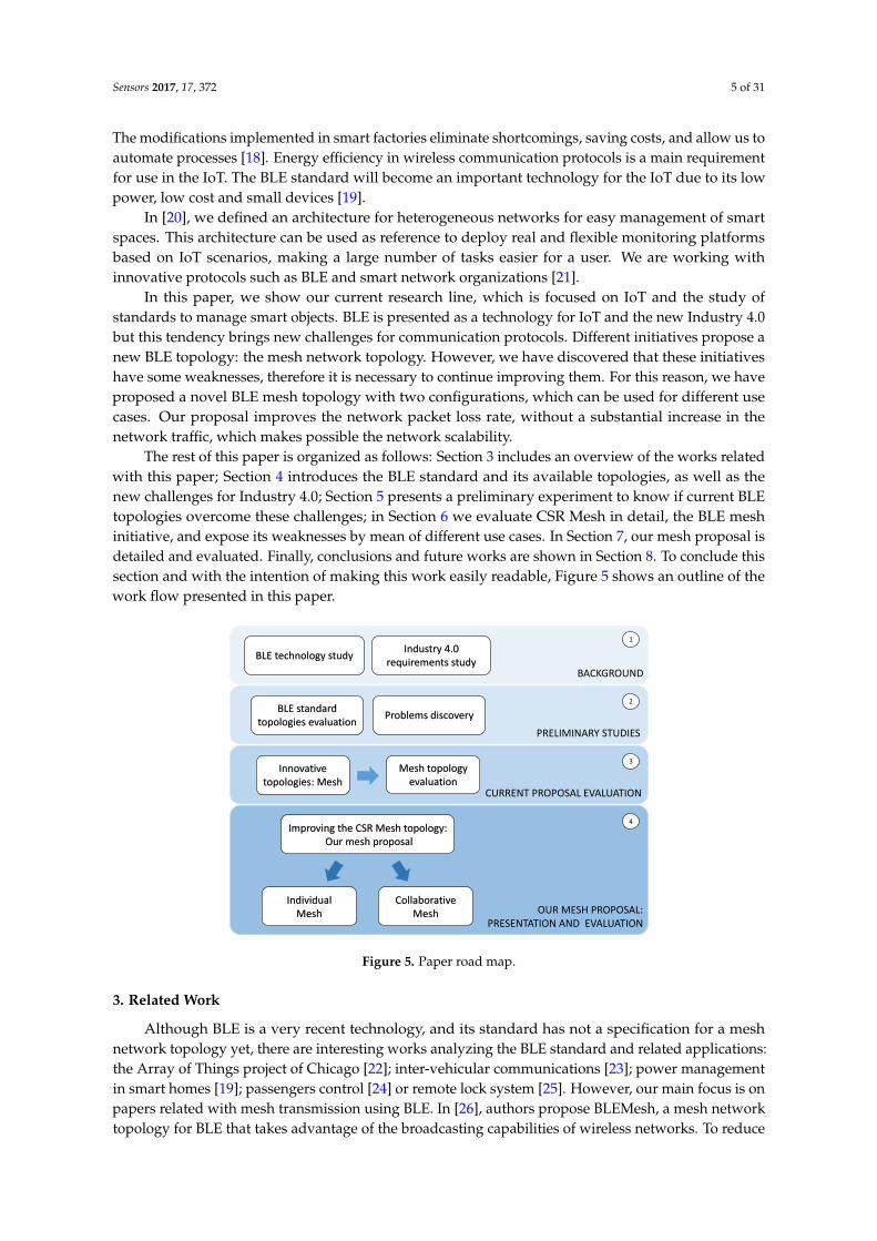
The rest of this paper is organized as follows: Section 3 includes an overview of the works relatedwith this paper; Section 4 introduces the BLE standard and its available topologies, as well as thenew challenges for Industry 4.0; Section 5 presents a preliminary experiment to know if current BLEtopologies overcome these challenges; in Section 6 we evaluate CSR Mesh in detail, the BLE meshinitiative, and expose its weaknesses by mean of different use cases. In Section 7, our mesh proposal isdetailed and evaluated. Finally, conclusions and future works are shown in Section 8. To conclude thissection and with the intention of making this work easily readable, Figure 5 shows an outline of thework flow presented in this paper.
Collaborative Mesh
Individual Mesh
Improving the CSR Mesh topology:Our mesh proposal
OUR MESH PROPOSAL:PRESENTATION AND EVALUATION
4
Mesh topology evaluation
CURRENT PROPOSAL EVALUATION
3Innovative
topologies: Mesh
BLE technology studyIndustry 4.0
requirements studyBACKGROUND
1
BLE standard topologies evaluation
PRELIMINARY STUDIES
2
Problems discovery
Figure 5. Paper road map.
3. Related Work
Although BLE is a very recent technology, and its standard has not a specification for a meshnetwork topology yet, there are interesting works analyzing the BLE standard and related applications:the Array of Things project of Chicago [22]; inter-vehicular communications [23]; power managementin smart homes [19]; passengers control [24] or remote lock system [25]. However, our main focus is onpapers related with mesh transmission using BLE. In [26], authors propose BLEMesh, a mesh networktopology for BLE that takes advantage of the broadcasting capabilities of wireless networks. To reduce

Sensors 2017, 17, 372 6 of 31
the number of packets retransmitted through the network, BLEMesh uses an opportunistic routingmethod. However, this proposal does not satisfy the Zero fails requirement of Industry 4.0. In [27] alight evaluation of a prototype of CSR mesh has been showed using the metric packet delivery ratio.After a not very clear study case, authors use the Octave simulator. They conclude that more studiesare needed. In [28] authors implement a synchronization protocol. With this protocol nodes can nottransmit in broadcast mode and then it will be impossible the free movement of the nodes such assmartphones, smartbands or different tools or instruments in the industry 4.0 environment.
On the other hand, the Bluetooth Special Interest Group (SIG) has officially announced theformation of the Bluetooth Smart Mesh Working Group, which will build the architecture forstandardized mesh networking capability for Bluetooth Smart technology [29]. A new Bluetoothspecification, Bluetooth 5 [30], has just been appeared, but there is no extra information about themesh topology.
Well-known companies have also shown interest in incorporating this new functionality to BLEtechnology. The most important initiatives are the Nordic Semiconductor [31] and Cambridge SiliconRadio (CSR) [32]:
• The Nordic project [33] was created in collaboration with the Norwegian University of Scienceand Technology [34] as part of a thesis and is not part of the official SDK of Nordic Semiconductor.This is an open project, which uses the broadcast data transmission. This project uses Nordicseries nRF51 [35] devices. These devices use BLE version 4.0, which causes packet loss inthe mesh, because devices are not able to receive packets while they are retransmitting thosealready received.
• CSR is a company that has opted for the development of a mesh network topology for BLE.CSR has developed devices which use BLE version 4.1: the smart Bluetooth CSR101x family [36],as well as a proprietary protocol built on BLE, called CSRmesh [37]. This protocol allows to createa mesh topology by transmitting and receiving broadcast packets, like other projects.
However, mesh topology is not an exclusive BLE topology: ZigBee uses mesh topology todeploy low-power WSN [13,38], it is also well-known in Wi-Fi [39,40] and it allows connectionsamong smartphones or tablets. However, BLE technology allows us to unify the advantages ofboth alternatives: to create low-power WSNs which are able to connect directly with users, usingtheir smartphones.
This BLE network topology proposals open a new possibility in the Industry 4.0, because it willallow us to cover large areas completely. Thus, static or mobile (users) devices which are in the meshcan communicate with the mesh server or any other mesh device, regardless of their location.
4. Materials and Methods
BLE appeared in the Bluetooth specification 4.0 [41] in 2010 as a breakthrough technology for IoT.Moreover, BLE has seen an uncommonly rapid adoption rate, and the number of products designsthat already include BLE puts it well ahead of other wireless technologies at the same point of time intheir release cycles. This rapid growth of BLE is relatively easy to explain: BLE has gone further fasterbecause its fate is so intimately tied to the phenomenal growth in smartphones, tablets, and mobilecomputing [16].
For the reasons described before, we selected BLE for detailed study and evaluation in real deviceson our real deployed network, to check its strong points and weakness. In addition, Fourth RevolutionIndustrial has created new requirements for communication standards, and BLE may be an interestingoption to manage indoor communications in future factories. In this section, BLE fundamentals areoverviewed: available network topologies, and new requirements for BLE. Later, hardware devicesused in our experiments are described.

Sensors 2017, 17, 372 7 of 31
4.1. Fundamentals
In this section, we do not attempt to explain BLE in detail. We present the main characteristicsnecessary to facilitate the understanding of our work. The first BLE specification included two networktopologies for data transmission: connection and broadcast, each one with its own advantages andlimitations. BLE versions 4.1 [42], 4.2 [43] and 5.0 [30] maintain these topologies, which have beenimproved by combining different roles. However, these later versions are not implemented in mostIoT devices. These two available topologies in BLE specification are described below:
• Connection topology: once the connection has been established, two BLE devices exchange packetsin a permanent and periodical way. Two roles are used here: master (central) and slave (peripheral).A master device can connect with different slave devices, setting up a star-topology network (seeFigure 6a). This operating mode allows the data exchange in both directions, between a slavedevice and the master device. In addition, a master device can use the notification and indicationcharacteristics to read data immediately when they change. According to BLE specification,the number of slaves supported simultaneously by a master is unlimited. However, in real devices,with real memory limitations, this number falls to 4–8 (depending on the device limitations).
• Broadcast topology: a BLE device can transmit data using the BLE advertising mode to any BLEdevice in listening range, which uses the BLE scanning mode. This topology defines two roles:broadcaster (device which transmits data) and observer (device which receives data). In this case,data exchange is unidirectional, from the broadcaster to one or more observers (see Figure 6b).
These network topologies are enough to cover small and medium IoT installations. However,the recent emergence of Industry 4.0 includes IoT networks in factories, and changes the requirementsof these networks. These new requirements are as follows [44,45]:
• Total coverage: the entire space of the building must be covered by the network, avoiding deadzones where the users can not communicate.
• Zero Fails: to provide a high performance, every transmitted packets must arrive at its destination,getting a success rate of 100% in communications and a PLR close to zero.
• Sustainability: covering both software (devices use efficient programs) and hardware (reducingthe number of devices and using a low power standard). In this context, two new concepts appear:green-by (IoT network linking physical devices with operators to afford efficient operation) andgreen-in (techniques to encourage the deployment of cost efficient networks) [46–48].
M
S
SS
S
S
S
B
BB
O
O
(a) (b)
Figure 6. Available topologies in BLE standard (version 4.0). (a) Connection topology: (M) Master;(S) Slave; (b) Broadcast topology: (B) Broadcaster; (O) Observer.

Sensors 2017, 17, 372 8 of 31
4.2. Mesh Topologies in BLE Standard
Future industrial networks will enable a wide range of devices and services to be connected.So that there will be a need to collect as much real-time relevant data as possible. It is estimated thatthe quantity of connected devices will double or triple [45]. Then, the challenge will be connectingthis large number of devices at the field level in a simple cost-efficient way. Of course demandingrequirements for performance and reliability will still need to be met. Perhaps future networks withhigh numbers of devices should be hierarchical to simplify network management and operation.The star topologies have some advantages, such as lower latency and higher reliability, but alsodisadvantages mainly the failure of a central device will disconnect all attached devices. Thus, the useof more complex structures, such as extensively meshed network topologies, will increase. With theadoption of new protocols, these networks will need less management efforts and will offer quicknetwork reconfiguration and service assurance [45].
As mentioned above, mesh network topology is not yet implemented in the BLE standard.Nevertheless, there are some initiatives which implement this topology over BLE. To explain in detailhow this topology is implemented, we have focused on CSR mesh, because their devices use BLEversion 4.1, which allows us to combine the different BLE roles.
CSR proposes the following mesh topology, built on BLE protocol, which uses three different BLEroles simultaneously:
• Broadcaster: CSR devices transmit data packets as broadcasters. These packets are coded andhave a format which does not follow completely the BLE standard. To ensure that the packetsarrive at the target device, the same packet is sent 3 times, the source device repeats 3 times thepacket sending.
• Observer: using BLE version 4.1, CSR combines broadcast role with observer role. Thus, devicescan receive packets from other devices at any time, even while they are transmitting their ownpackets. If received packets have the correct format and comply specific conditions, then they arerepeated in broadcast again. This action increases the global coverage of the source device, andthe network traffic.
• Advertiser: this role enables other devices to establish a master-slave connection. Being a partiallyclosed protocol, CSR introduces new devices in their mesh using a direct connection to one of itsnodes, which will work as a bridge between the new device and the rest of the mesh, it means,repeating the original data with the proper format.
Thus, mesh topology created by CSR uses a flood mesh protocol. Nevertheless, the main problemof this routing protocol is the high number of retransmissions [49], which we will try to reduce. For thisaim, now we need to define two parameter which we will use in our study:
• Time To Live (TTL): one byte of the packet indicates the maximum number of times this packetcan be retransmitted, or the maximum number of hops among devices possible. Each time adevice receives and retransmit a packet, this number is decremented, discarding the packet if thisbyte is 0.
• Package ID: each of the packets transmitted by a device has an identifier, which will be the samewhile the packet remains in the network. This identifier allows devices to discard packets thathave previously retransmitted, checking only this field.
4.3. Hardware Platform
This section shows the BLE devices used in our studies and experiments. We have chosenWaspmote devices from Libelium [50], because they can be equipped with multiple sensors and BLE4.0 radio chips, and CSR1010 devices for evaluating their BLE 4.1 radio chips in mesh network topology.
Waspmote is a modular device (see Figure 7), which allows us to deploy WSNs using a largenumber of protocols for data transmission by means of different modules. Its specifications are:

Sensors 2017, 17, 372 9 of 31
microcontroller ATmega1281 (14.7456 MHz); SRAM memory (8 KB), EEPROM (4 KB), FLASH (128 KB)and SD (2 GB); clock RTC (32 KHz); dimensions of 73.5 × 51 × 13 mm (L × W × H) and weight of20 gr; and finally, different operation levels to reduce the consumption: ON (15 mA), Sleep (55 µA),Deep Sleep (55 µA) or Hibernate (0.07 µA). Libelium provides us with multiple options to choose awireless communication protocol. Specifications of the BLE radio module are: chipset BLE112 fromBlueGiga [51]; RX sensibility of −103 dBm; TX Power interval between −23 dBm and +3 dBm; antennaof 5 dBi; security using AES-128; range of 100 m; consumption modes: sleep (0.4 µA)/RX (8 mA)/TX(36 mA).
Figure 7. Waspmote devices equipped with BLE module.
CSR1010 devices (see Figure 8) have a BLE 4.1 radio with direct single-ended 50 Ω antennaconnection, which allows them to transmit BLE data in any direction, at a distance between 20 and30 m depending on existing obstacles; a 16-bit microprocessor with 64 Kbytes RAM and 64 KbytesROM; 1 µA integrated key scanning hardware; PWMs and quadrature decoders; peripheral I2C andSPI (debug); analog IOs and UART interface; up to 32 re-assignable programmable digital IOs; up to4.4 V direct supply connection for Li-poly batteries.
Figure 8. CSR1010 device [36].
5. Preliminary Evaluation: BLE Standard Topologies for Industry 4.0
A preliminary study has been carry out to determine if the available network topologies aresuitable for new Industry 4.0 challenge. For this study, Waspmote devices with a BLE radio modulehave been used to deploy our BLE network.
Thus, a 10-BLE-device network was deployed in our institute, I3A. For data transmissions, devicesuse the broadcasting capability: the static BLE devices transmit packets as broadcasters, and an userequipped with a mobile device (which is a observer) receives these packets in different points while heis moving through the building (from P1 to P16 in Figure 9). Measurements relating to the number ofpackets and their RSSI have been taken in different points of the walk-through of the user to knowif the deployed network works correctly. Figure 9 shows the situation of the static BLE broadcasters(D1, ..., D10) and Testing Points (P1, ..., P16). It has also been shown what we have called Good Points

Sensors 2017, 17, 372 10 of 31
and Bad Points. In Good Points, the greatest RSSI corresponds to packets from the nearest device;Bad Points show both, where the higher RSSI received packets do not come from the nearest device,or the observer has not received any packet from this nearest static device.
Planta primera0 5
D1 D2
D3
D4 D5
D6
D7D8
D9D10
P1 P2 P3 P5
P4
P6P7
P16
P15
P14 P12P13
P11
P10P8
P9
Lab1 Lab2
Lab3Lab4 Lab5
D1, .., D10P1, .. , P16 Testing Points BLE broadcastersGood point: the highest RSSI received corresponds to the nearest broadcasterBad point: the highest RSSI received does not correspond to the nearest broadcaster
Figure 9. Results obtained in preliminary test to check the performance in a BLE IoT installation.
As Figure 9 shows, only 68.75% of the testing points are Good Points, where the observer receivedpackets from the nearest static device correctly. These results leads us to conclude that this topologydoes not fulfil the requirements of the Industry 4.0 identified above: there are several dead zoneswhere there is not network coverage, and the PLR is too high.
Furthermore, connection topology has been dismissed due to the restriction in the number ofslaves connected simultaneously to a master (this number depends on the memory of device, and,in practice, this number is 8 at maximum), and the impossibility of deploying a network hierarchyby means of connecting a master with other master devices working as slave (this characteristic wasincluded in the specification 4.1 of Bluetooth [42], but most devices do not implement it). In mostIndustry 4.0 use cases, just 8 slave devices connected to a master device are not enough, because this isa very static and limited option, due to every slave device should be within the master slave range. Inaddition, these limitations affect the coverage of the network, and make hard to scale the network,which has a negative impact in its sustainability.
Once the current topologies specified in the Bluetooth standard have been ruled out for use inIndustry 4.0 due to it does not meet its requirements, a new BLE network topology is necessary: meshtopology. As seen before, there are already some initiatives to use this topology in BLE technology.However, these first versions have weaknesses which are necessary to solve. So that, in followingsections, we will present our new topology proposal. Moreover, it will be compared with the currentinitiatives, evaluating its performance and demonstrating that its packet loss is lower.
6. Discussion
This section is related in the following way: firstly, CSR devices and CSR Mesh are evaluated;secondly, problems found in this evaluation are established. In this way, the study cases are:
• Study of PLR in CSR devices. One of the most important requirements in Industry 4.0 is theZero fails objective, to provide a high performance in networks, so this rate has a great impact.For this reason, to know the PLR for these devices in optimal conditions is necessary.
• Coverage study for CSR devices in real environments, which allows us to deploy a real networkin a real environment.

Sensors 2017, 17, 372 11 of 31
• CSR Mesh evaluation in a real environment.
6.1. Packet Loss Rate in CSR Devices
As described above, packets are retransmitted three times in the CSR Mesh as a reliability measureand to ensure that the transmitted packets are received in different devices. When a device receives apacket, it retransmits this packet three times if it is not the destination device. If the same packet isreceived more than once, it is discarded and no action is taken. We have carried out a study to verify ifthis way of working is enough to provide the needed performance.
A simple mesh network was deployed for this experiment. This network had a single broadcasterdevice and a single observer device (CSR1010). The broadcaster sent packets to the observer. The studyhas been carried out by evaluating the PLR according to the number of repetitions of each packet.A new packet was transmitted each 5 s for 3000 s. If the repetitions were configured in broadcaster,a new packet and its repetitions were transmitted each 5 s. This experiment tried to evaluate the impactof this measurement on the network, so that the devices were in optimal conditions for transmittingand receiving data: in a direct line of sight and separated 50 cm, minimizing the packet loss due todistance or obstacles.
Table 1 shows the PLR for packets transmitted once, twice or three times. These results reflectan improvement when the number of transmitted packets grows. A PLR of approximately 16% wasobserved for packets transmitted only once; 3% when packets were repeated twice and 0% when thenumber of repeated packets was three. The need of transmitting three times is due to the fact that theBLE radio is not only used to receive packets, it has also to transmit advertisement packets (i.e., otherdevices can use this device like a bridge) and moreover, the radio must retransmit the received packets.
Table 1. PLR (%) in data transmission between a single broadcaster and a single CSR observer device,according to the number of packet repetition.
Transmissions of EachData Packet
Packet Loss Rate (%)for Original Packets
1 16.24
2 2.79
3 0.00
As this basic experiment shows, the operating mode taken by CSR mesh topology based onrepeating the packets 3 times ensures the arrival of all packets, but increases the traffic of the network,the power consumption and the packet collisions in a saturated wireless frequency band. It couldtrigger a scalability problem when the number of devices in the network increases.
A new experiment was carried out to evaluate these new problems in a real network. In thisnew experiment, a network was deployed using a higher number of network devices to cover a realbuilding, emulating a factory. However, before the network deployment, a coverage study was needed.
6.2. Coverage Study for CSR Devices
When deploying a real wireless sensor network, the first step is to carry out a coverage study todetermine the least number of needed devices to cover the largest possible area with the lowest cost.For this reason, this coverage study was performed in the first floor of our research institute (48 m inlength and 15 m in width).
An important consideration when we want to evaluate the range of a device is the antenna.CSR1010 devices have an Inverted-F Antenna [52]. The radiation pattern in this antenna is circular inthe XZ plane. So, we can distinguish two different area according to the device placing: the coveragerange is favourable in the XZ plane (see Figure 10) and unfavourable in the rest of the plans.

Sensors 2017, 17, 372 12 of 31
Figure 10. X, Y and Z plans in a CSR1010 device.
In open areas with a direct line sight, the coverage range of CSR1010 devices is around 30 m.However, this range is lower in inside environments with obstacles, so it was necessary a study toevaluate this range in our laboratory.
In this experiment, two devices were used: a broadcaster placed 4 m from a observer, withconstructive elements between them (see Table 2). This study is not used for any building, it means,it must be repeated for any building to ensure the minimum number of devices needed to cover itsown area. In our experimental scenarios, 80 RSSI samples were taken in coexistence with other wirelesstechnologies (Wi-Fi and ZigBee).
For each evaluated scenario, two experiments were carried out, regarding the device position:favourable and unfavourable position. The obtained results are shown in Table 2.
Table 2. Average RSSI obtained in different scenarios.
Scenario Description RSSI with FavourableAntenna Position on Average
RSSI with UnfavourableAntenna Position on Average
Direct Line of Sight −67 −57
Dividing panels −65 −63
Doors −68 −73
Columns −80 −83
Walls −60 −62
Walls + storage racks −79 −95
Glass −65 −70
Using this previous evaluation, we were able to study how different construction elements affectthe coverage range. For this purpose, we deployed a mesh network, avoiding the problematic elements,like columns, walls and particular storage racks.
We begun deploying a 10-CSR device network. Of course, all coverage area was covered, but ouraim was to know the minimum number of devices needed to cover it. So that, the number of deviceswas gradually decreased up to we found that two devices were not able to cover the whole area.Therefore, we established that the minimum needed devices to cover this area was three.
6.3. CSR Mesh Evaluation
Once we studied the behaviour of a single CSR device in optimal conditions, we wanted to knowhow really a CSR Mesh network works. For this purpose, the following steps were followed:
• By the previous coverage study, three CSR devices are needed to cover the first floor of ourresearch Institute
• To guarantee a test environment as real as possible, we emulated an industrial environment whereit was necessary to measure different parameters which were processed by a BLE controller. To do

Sensors 2017, 17, 372 13 of 31
this, two Waspmote devices equipped with sensors were added into the mesh, using CSR devicesas a bridge (following CSR topology). These Waspmote devices transmitted sensor data packetevery five seconds. In addition, a BLE controller which receives, processes and stores BLE packets,was also introduced using the remaining CSR device. Figure 11 shows the final arrangement ofthe devices.
• In addition, to determine the influence of repeating packets on a real mesh network, CSR deviceswere configured with two different settings: transmitting each packet once, and transmitting threetimes (default mode).
• Finally, for each of the proposed configurations, the PLR was measured, as well as the number ofpackets received in each CSR device per second, to evaluate the packet traffic in network.
Planta primera0 5
W2
W1
CSR1
CSR3CSR2
Lab1 Lab2
Lab3Lab4 Lab5
CSR devices Waspmote devicesMaster-slave connection Mesh transmission (Broadcast)
BLE Controller
Figure 11. Network deployed using 2 sensor devices and CSR mesh topology.
Tables 3 and 4 show the network traffic (sent and received packets, respectively, by differentdevices). As a result of the mesh network topology, the broadcast mode and the proprietary code ofthe CSR devices, a typical traffic matrix is not available. Table 3 shows the number of packets sent byWaspmote devices (W1 and W2) and the number of these packets received by the BLE server, for twodifferent network configuration. It can be observed that the number of packet repetitions is especiallyrelevant for packets from W2, which have to be retransmitted by three different devices (CSR3, CSR2and CSR1) and finally received by the BLE server. On the contrary, for packets from W1, which wereretransmitted from CSR2 to CSR1, there are no significant differences when changing the configuration.
Table 3. Packets sent by sensor nodes and received by BLE server, for each CSR devices configuration.
Sensor Nodes
CSR Devices TransmitEach Packet Once
CSR Devices TransmitEach Packet Three Times
Sent Packets Packets Receivedby Server Sent Packets Packets Received
by Server
W1555 (to CSR2,
master-slave connection) 554577 (to CSR2,
master-slave connection) 575
W2551 (to CSR3,
master-slave connection) 367577 (to CSR3,
master-slave connection) 542
Table 4 shows the number of packets received by different CSR devices, as well as BLE server.From these results, important information has been obtained. Firstly, the number of received packetsgrows when the number of repetitions is higher. In other words, the network traffic is higher whenCSR devices transmit each packet three times. Secondly, CSR1 device performed an important packetfiltering, since only 42% of packets for the first configuration and 31% of packets for the secondconfiguration are original packets, i.e., not repeated packets. Therefore, this connection will be

Sensors 2017, 17, 372 14 of 31
maintained in following evaluations. Thirdly, there is an increase in the number of packets receivedby CSR3 device higher than the increase in the number of packets received by CSR2. It is quite theopposite to what is expected since the CSR2 device is located in the middle of the mesh network,so that it must receive packets from all the rest nodes in the mesh. This behaviour is unsuitable andends up in troubles when the network has a high number of devices.
Table 4. Packets received by CSR devices and BLE server in CSR Mesh evaluation, for each CSRdevice configuration.
ConfigurationPackets Received by
CSR1 CSR2 CSR3 Server
CSR devices transmiteach packet once 2186 4957 3778 921
CSR devices transmiteach packet three times 3629 5542 6003 1117
In Table 5 it can be observed the PLR of each sensor node, which are the source of the information.In the first configuration, CSR devices retransmitted each packet once, while in second configurationCSR devices repeated each packet three times. These packets could contain different data (includingkey data), therefore avoiding their loss can be crucial. The first conclusion we can draw is quiteexpected the results show a lower packet loss when CSR devices repeat each packet three times insteadof one (3.21% against 16.73% on average). The second conclusion is related to the device positioning:the Waspmote 1 results are much better than the Waspmote 2 results due to the second one is fartherfrom BLE controller (see positioning in Figure 11), so that, its packets need to be retransmitted by moredevices (increasing their network hops).
Table 5. PLR for 2 sensor devices using the CSR mesh topology, for different CSR device configurations.
ConfigurationPacket Loss Rate (%)
Waspmote 1 Waspmote 2
CSR devices transmiteach packet once 0.18 33.39
CSR devices transmiteach packet three times 0.35 6.07
As stated above, an important parameter of this type of network is the number of packets whichare moved by devices at any given time (network traffic). Therefore, the number of packets received inthe CSR devices were measured. These packets could be repeated (either a repetition from the samedevice, or a retransmission from another device), so that, the CSR devices must filter them and removethe duplicate ones. Referring to this, Table 6 shows the number of packets per second in each CSRdevice, for two possible configurations: CSR devices retransmit each packet once or three times.
Table 6. Packets per second received by CSR devices in a network with 2 sensor devices and CSRmesh topology.
ConfigurationPackets Received per Second
CSR1 CSR2 CSR3 Average
CSR devices transmiteach packet one 0.62 1.41 1.08 1.04
CSR devices transmiteach packet three times 1.16 1.76 1.91 1.61

Sensors 2017, 17, 372 15 of 31
In the Table 6 we can see the payment required to achieve that low PLR (see Table 5): each CSRdevice received 0, 57 more packets per second on average when they repeated the received packetsthree times. Although it may not seem too much, it can make the situation unsustainable if the numberof devices in the network is increased (in this case, the number of sensor devices was only 2, and thenumber of total network devices was 6).
As seen from this experiment, the PLR in CSR Mesh is acceptable, although for this acceptablePLR packets must be retransmitted three times. In addition, CSR Mesh is a proprietary protocol builton BLE, and scalability problems arise when different BLE devices are included in network, becausethey need a CSR device working as slave to bridging them with the rest of the network. The maximumnumber of non-CSR devices on mesh network is the number of CSR devices in it. Moreover, if a widercoverage range is needed, more CSR devices must be included. To solve these scalability problems,we propose some improvements. In our proposal, any BLE device with the observer and broadcasterroles, could take part in the network, and no bridge device is necessary. In next section, this proposalis detailed, as well as some experiments which were carried out to evaluate its packet loss and itsnetwork traffic.
7. Improving the CSR Mesh
As already described, one of the weaknesses of the CSR mesh network is its scalability, especiallywhen new sensor devices are adding to it: to introduce a new non-CSR devices on network, the useof a CSR device as bridge is necessary. Because of great impact that BLE mesh network topology canhave on the Industry 4.0, this network scalability must be complete, irrespective of the devices whichconform the network. After the study of the behaviour of the CSR mesh, we decided to develop anew mesh proposal based on it. While to connect an external device to a bridge CSR device usinga master-slave connection is necessary in the CSR mesh to take part of this network, our proposalremoves this restriction. In this way, all BLE devices could broadcast packets with the specified format,which are retransmitted to their destination.
Although the behaviour of the devices may seem similar, there are important differences betweenthe protocol proposed in this section and CSR Mesh, namely:
• Our proposal is an open protocol, in contrast to CSR Mesh. It allows us to implement our protocolin any BLE device. In addition, this characteristic will be very useful for future evaluations.
• Bridge devices are not needed. In our proposal, any BLE device can take part of the mesh network,because all nodes broadcast their data packets to their neighbours. It improves the scalability andthe cost savings, due to bridge devices are not needed for each new added device in the network.
• Master-slave connection is not required in our proposal. It greatly improves the inclusion ofmobile devices (like users smartphones). In this way, a user could move freely within meshnetwork, without worrying about master-slave connection interruptions.
In addition to these important differences, for our mesh proposal, a new packet format wasdefined. This packet format is compatible with CSR devices, so that these devices can be includedin our mesh as a backbone of it, since their BLE 4.1 chips allow us to obtain a better performance inthis use case than if we used only BLE 4.0 chips. This better performance is due to the possibility ofusing observer and broadcaster modes simultaneously, without the need to switch them. A single BLE4.0 radio only can transmit or receive data at a certain point. However, using BLE 4.1, to change themode of operation from observer to broadcaster (or vice versa) is not necessary. It allows us to takeadvantage during the idle periods for doing other useful actions. Figure 12 shows these differencesbetween BLE version 4.0 and 4.1:

Sensors 2017, 17, 372 16 of 31
Adv Idle Adv Idle Adv Idle Adv Idle Adv Idle Adv Idle Scan
Advertising Time
Advertising Interval
Observer ModeBroadcaster Mode
Scanning TimeAdvertising Interval
(a)
Adv Scan Adv Scan Adv Scan Adv Scan Adv Scan Adv Scan Adv Scan …
Advertising Time
Advertising Interval
Broadcaster and Observer Mode
Advertising IntervalAdvertising Interval
(b)
Figure 12. Differences between Advertising and Scanning processes in BLE version 4.0 and 4.1.(a) Advertising and Scanning processes in BLE 4.0; (b) Advertising and Scanning processes in BLE 4.1.
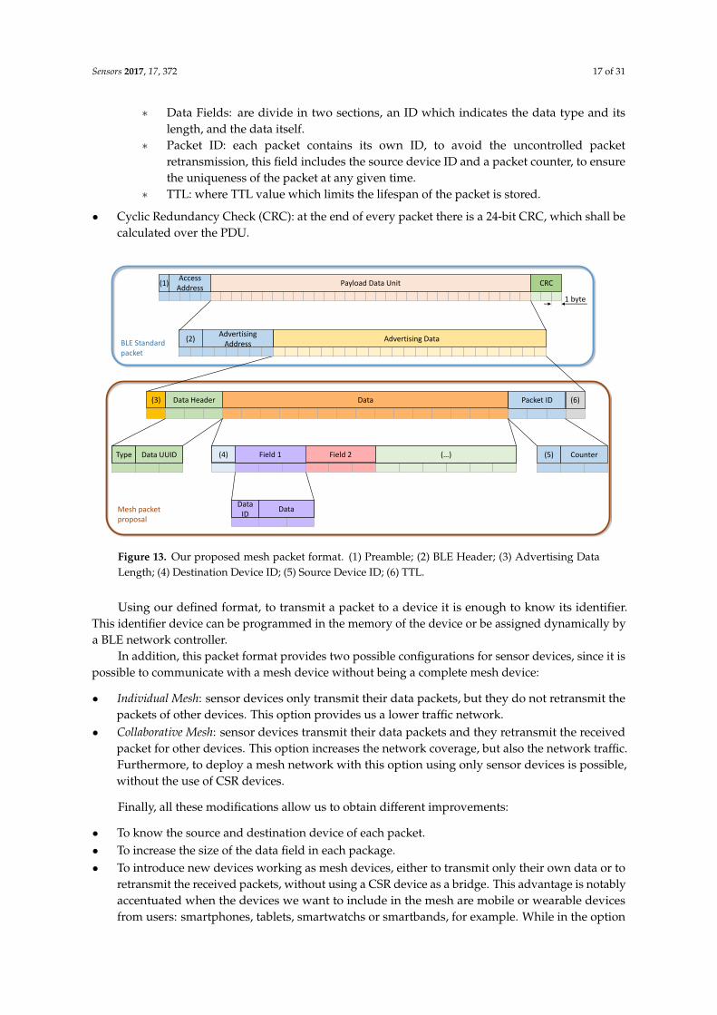
As said above, we created our own packet format since CSR uses its proprietary packet formatfor its proprietary mesh protocol, and it is not available for users. However, in our proposal, we havedeveloped our packet format following BLE standard, and it is compatible with CSR devices, to givethe choice of including them in the network. Thereby, any two devices can communicate using themesh when both of them are inside its coverage range. In this way, devices only have to transmitan advertising package, following the defined format, in their broadcaster mode to transmit data.Figure 13 shows our proposed format, which can be used by any developer to create a new meshnetwork. This packet format follows the BLE specification, so that, the most of its fields can beconsulted in [41]. These fields are shown below:
• Preamble: all BLE packets have an eight bit preamble, which is used in the receiver forfrequency synchronization, symbol timing estimation, and Automatic Gain Control trainingtasks. In advertising packets, as in this case, preamble must be 0xAA.
• Access Address: in advertising packets, access address is a 32-bit value, and for advertisingpackets shall be 0x8E89BED6.
• Payload Data Unit (PDU): packets have a variable size payload, from 12 to 37 bytes,which includes:
– Header: a 16-bit header, where PDU type is specified. This PDU type is non connectableundirected advertising, which is used in broadcast data transmissions.
– Advertising Address: this 6-octet field contains the BLE address. In our proposal this isa random address generated by device.
– Advertising Data: this variable size field (from 4 to 31 bytes) contains data collected fromsensors or device information (battery level, for example). Advertising Data contains thefollowing fields:
∗ Advertising Data Packet Length: following the BLE standard, first octet contains thePDU length.
∗ Data header: contains two different fields. The first field is Type which indicates the PDUservice. For mesh packets, its value is 0x16 (service data). The second field is a 16-bitUUID. To ensure the compatibility with CSR devices, the UUID for his packets shall bethe CSR UUID.
∗ Destination Device ID: due to the use of random address, devices use an ID to identifythem, which is shorter than a BLE address.
Sensors 2017, 17, 372 17 of 31
∗ Data Fields: are divide in two sections, an ID which indicates the data type and itslength, and the data itself.
∗ Packet ID: each packet contains its own ID, to avoid the uncontrolled packetretransmission, this field includes the source device ID and a packet counter, to ensurethe uniqueness of the packet at any given time.
∗ TTL: where TTL value which limits the lifespan of the packet is stored.
• Cyclic Redundancy Check (CRC): at the end of every packet there is a 24-bit CRC, which shall becalculated over the PDU.
Data(3) Data Header (6)Packet ID
Type Field 1 Field 2 (…)
Data ID
Data
(4)
(2)Advertising
AddressAdvertising Data
(5) CounterData UUID
Access Address
Payload Data Unit CRC
1 byte
(1)
BLE Standard packet
Mesh packet proposal
Figure 13. Our proposed mesh packet format. (1) Preamble; (2) BLE Header; (3) Advertising DataLength; (4) Destination Device ID; (5) Source Device ID; (6) TTL.
Using our defined format, to transmit a packet to a device it is enough to know its identifier.This identifier device can be programmed in the memory of the device or be assigned dynamically bya BLE network controller.
In addition, this packet format provides two possible configurations for sensor devices, since it ispossible to communicate with a mesh device without being a complete mesh device:
• Individual Mesh: sensor devices only transmit their data packets, but they do not retransmit thepackets of other devices. This option provides us a lower traffic network.
• Collaborative Mesh: sensor devices transmit their data packets and they retransmit the receivedpacket for other devices. This option increases the network coverage, but also the network traffic.Furthermore, to deploy a mesh network with this option using only sensor devices is possible,without the use of CSR devices.
Finally, all these modifications allow us to obtain different improvements:
• To know the source and destination device of each packet.• To increase the size of the data field in each package.• To introduce new devices working as mesh devices, either to transmit only their own data or to
retransmit the received packets, without using a CSR device as a bridge. This advantage is notablyaccentuated when the devices we want to include in the mesh are mobile or wearable devicesfrom users: smartphones, tablets, smartwatchs or smartbands, for example. While in the option

Sensors 2017, 17, 372 18 of 31
proposed by CSR a device must establish a master-slave connection that will be lost when theuser leaves the range of coverage of the bridge device, our option allows us to transmit packets tothe network in general, accentuating the concept of mesh and total coverage.
• To add new devices, no matter how many bridge devices are available, since they are no required.In this way, our network provides increased scalability, sustainability, and saving cost, becausewe can eliminate CSR bridge devices, reducing the final number of network devices withoutcompromising the network performance.
7.1. Evaluation of Our New Mesh Proposals
After the description of our mesh topology proposal, an in-depth study about its behaviour isnecessary. In this study, we took advantage of the scalability of our proposed mesh and the possibilityto include any type of device. So that, we used 8 Waspmote devices, 3 CSR devices and a BLE controller.In addition, Waspmote devices were configured in the two settings before defined: Individual Mesh andCollaborative Mesh.
To evaluate the behaviour of our mesh topology proposal and its scalability, these steps havebeen followed:
• Three CSR devices were deployed following the previous coverage study.• As in previous experiments, an industrial environment was emulated where different parameters
were measured. A BLE controller was included in the network using a master-slave connection(CSR1-BLE controller) to take advantage of the BLE 4.1 radio used by CSR devices. Moreover,in this experiment, 8 Waspmote devices equipped with sensors were included. These devicesmonitored different parameters, and transmitted their data each 5 s. Figure 14 shows thedeployed network.
• Network configurations have been defined: Individual Mesh and Collaborative Mesh. For eachconfiguration, the PLR for each Waspmote device and the number of packets per second receivedby each CSR was measured.
Planta primera0 5
W6
W8
CSR1 CSR3CSR2
Lab1 Lab2
Lab3Lab4 Lab5
CSR devices Waspmote devicesMaster-slave connection Mesh transmission (Broadcast)
BLE Controller
W1W3
W7
W5W4W2
Figure 14. Network deployed using 8 sensor devices without master-slave connection.
In the following sections, the behaviour of both configurations has been detailed. Moreover, foreach configuration, a study for Low Network Load and High Network Load were carried out. On theone hand, using a Low Network Load, Waspmote devices repeat each packet once, which reduces thenetwork traffic and the network PLR. On the other hand, using a High Network Load, Waspmote devicesrepeat each packet three times, which increases the network PLR and the network traffic. To choosethe best option, the following studies were carried out.

Sensors 2017, 17, 372 19 of 31
7.2. Individual Mesh Evaluation
In this section we evaluate the first Waspmote device configuration: Individual Mesh. As statedbefore, using this configuration, Waspmote devices transmit their data packets using our mesh packetformat and receive packets from others devices; if this device is the destination, it process the packet;else, the packet is discarded.
The main improvement over CSR Mesh is the scalability: this mesh network was deployed using3 CSR devices and 9 final devices (8 sensor devices and 1 BLE controller). It increases the networksustainability and reduces the cost (to deploy a network with 200 sensor devices is not necessary to use200 bridge devices). In addition, the total coverage range of network is maintained, since the numberof devices which retransmit the packets is the same.
As seen before, the CSR devices retransmit each received packet 3 times by default. Although thisnumber can be reduced, the network PLR is increased. For this reason, our mesh proposal has beenevaluated using both CSR device configurations.
7.2.1. CSR Devices Retransmit Each Packet Three Times: Default Mode
In this evaluation, CSR devices were configured in default mode, while Waspmote devices wereusing the two different configurations described before: Low Network Load (each packet is transmittedonly once by Waspmote devices) and High Network Load (each packet is transmitted three times byWaspmote devices).
Tables 7 and 8 show the received and sent packets, respectively, by different devices in this study.Specifically, Table 7 shows the number of received packets by CSR devices and by BLE server. As saidbefore, CSR devices process the received packet, and retransmit it only the first time it is received(the repeated packets are discarded). However, the CSR API is not completely open, and to know thenumber of retransmitted packets is not possible. Results show an increase of the number of receivedpackets in the High Network Load configuration, due to the high number of original packets from eachsensor node (see Table 8) and the number of repetitions for each original packet (three instead of one).In this case, the node with the highest number of received packets is CSR2, due to its placement (seeFigure 14).
Table 7. Number of packets received by CSR devices and BLE server for each Waspmote deviceconfiguration in Individual Mesh with CSR devices retransmit each packet three times.
Number of Packets Transmittedby Waspmote Devices
Packets Received by
CSR1 CSR2 CSR3 Server
1 (Low Network Load) 15,587 26,306 21,618 4761
3 (High Network Load) 23,950 43,306 32,070 6132
Table 8 shows the number of original packets sent by sensor nodes for each network configuration(Low Network Load and High Network Load). In this case, sensor nodes sent broadcast packets to alldevices in their coverage range, so that, it is not possible to know the receiver device. Despite of thisfact, all sensor nodes sent a similar number of packets for each configuration, being received a highernumber of packets for the second configuration.
As Figure 15 shows, even using a Low Network Load, the PLR average (1.89%) was lower thanthe PLR average from CSR Mesh (around 3%) using the recommended configuration. In addition,the network deployed to evaluate our proposal had 8 sensor devices, compared with the 2 sensordevices used in CSR Mesh (is not possible to include a higher number of sensor devices in CSR Meshdue to the bridge restriction).

Sensors 2017, 17, 372 20 of 31
Table 8. Number of packets sent by each sensor node and received by BLE server, for each Waspmotedevice configuration in Individual Mesh with CSR devices retransmit each packet three times.
Sensor NodesLow Network Load High Network Load
Sent Packets Packets Receivedby BLE Server Sent Pakcets Packets Received
by BLE Server
W1 644 633 781 780
W2 582 571 811 810
W3 594 576 745 744
W4 588 579 748 746
W5 607 598 763 760
W6 635 623 768 764
W7 627 613 747 747
W8 576 568 782 781
Moreover, Figure 15 shows the PLR for High Network Load configuration: if Waspmote devicestransmit each packet 3 times, the network PLR is, on average, only the 0.21%.
0%
2%
4%
6%
8%
10%
12%
14%
16%
18%
20%
22%
24%
W1 W2 W3 W4 W5 W6 W7 W8
Pack
et L
oss
Rat
e
Sensor devices
Low Network Load High Network Load
Figure 15. PLR in our mesh proposal for 8 sensor devices with Individual Mesh configuration and 3 CSRdevices with default configuration.
Another important parameter to be considered is the network traffic, specially in mesh topologies.Table 9 shows the packets received per second in CSR devices. As it can be seen, even though using theHigh Network Load configuration, the number of packet received by CSR devices was 8.338 on average.In CSR Mesh, we obtained 1.61 packets per second in CSR default mode, but number of sensor deviceswas only 2. In addition, using the Low Network Load, a lower number of packets per second is receivedby CSR devices (6.564 on average), reducing the traffic network.
Table 9. Packets per second received by CSR devices when they retransmit each packet 3 times (defaultmode). Waspmote devices configured as Individual Mesh.
Number of Packets Transmittedby Waspmote Devices
Packets Received per Second
CSR1 CSR2 CSR3 Average
1 (Low Network Load) 4.833 8.157 6.703 6.564
3 (High Network Load) 6.031 10.906 8.076 8.338

Sensors 2017, 17, 372 21 of 31
In this study, we can see the advantages of our mesh proposal with regard to CSR Mesh topology:our mesh proposal increases the network scalability, and reduces considerably the costs, because theuse of CSR bridge devices is not necessary. Moreover, the network PLR has been reduced, and thenetwork traffic is maintained.
Finally, it is possible to reduce further the traffic network, reducing the number of packetretransmitted by CSR devices. Although this measure reduces the network PLR (the default CSRdevice configuration is modified), to evaluate the behaviour of this configuration in a real environmentis interesting. Therefore, next section shows the evaluation for Individual Mesh configuration, reducingthe number of packet retransmitted by CSR devices.
7.2.2. CSR Devices Retransmit Each Packet Once
In this experiment, CSR devices were configured in a saving mode, retransmitting each receivedpacket once, while Waspmote devices used both two available configurations in our mesh proposal:Low Network Load (each packet is transmitted only once by Waspmote devices) and High Network Load(each packet is transmitted three times by Waspmote devices).
Tables 10 and 11 contain data relating to network traffic. Specifically, Table 10 shows the number ofpackets received by CSR devices, as well as the number of original packets received by the BLE server.As we can see, the highest number of packets is received by CSR2 and CSR3 devices (especially CSR2)for both configurations, due to sensor nodes placement (see Figure 14). Analysing each configuration,an important increase in the number of packets is observed for High Network Load configuration(198% for the CSR devices, on average, compared to Low Network Load), although the number ofpackets received by the BLE server is increase only a 12.4%.
Table 10. Number of packets received by CSR devices and BLE server for each Waspmote deviceconfiguration in Individual Mesh with CSR devices retransmit each packet once.
Number of Packets Transmittedby Waspmote Devices
Packets Received by
CSR1 CSR2 CSR3 Server
1 (Low Network Load) 7172 11,481 9197 4814
3 (High Network Load) 15,628 20,480 18,395 5410
Table 11 shows the number of packets sent by each sensor node. Although knowing the immediatedestination node is not possible due to the broadcast topology, the number of packets received in thefinal destination node (BLE server) is showed. In this case, the number of received packets by BLEserver is increased when the High Network Load configuration is used, as we will analyse later.
Table 11. Number of packets sent by each sensor node and received by BLE server, for each Waspmotedevice configuration in Individual Mesh with CSR devices retransmit each packet once.
Sensor NodesLow Network Load High Network Load
Sent Packets Packets Receivedby BLE Server Sent Pakcets Packets Received
by BLE Server
W1 677 642 669 668
W2 668 624 695 695
W3 646 610 681 678
W4 632 590 670 669
W5 637 538 684 679
W6 660 611 682 675
W7 672 587 681 681
W8 654 612 669 665

Sensors 2017, 17, 372 22 of 31
As Figure 16 shows, the network PLR average was lower for these configurations, comparedwith the PLR average from CSR Mesh when CSR devices retransmit each packet once: 8.25% for LowNetwork Load and 0.39% for High Network Load, compared with the 16.73% for CSR Mesh retransmittingeach packet once. The PLR for High Network Load is notable, specially for Industry 4.0 requirements.
0%
2%
4%
6%
8%
10%
12%
14%
16%
18%
20%
22%
24%
W1 W2 W3 W4 W5 W6 W7 W8
Pack
et L
oss
Rat
e
Sensor devices
Low Network Load High Network Load
Figure 16. PLR in our mesh proposal for 8 sensor devices with Individual Mesh configuration and 3 CSRdevices with saving configuration.
Table 12 shows the traffic network, measured in packets per second received in CSR devices.As seen in CSR Mesh experiment, when packets were retransmitted only once, 1.04 packets werereceived in each CSR device, on average, for two sensor devices. Using our mesh proposal, we achieveda 2.71 packets per second received by each CSR device, on average, for 8 sensor devices configuredwith a Low Network Load, which guarantees the network scalability. Moreover, to minimize the PLR ispossible using High Network Load configuration, although network traffic is slightly higher (5.19 onaverage for 8 sensor devices).
Table 12. Packets per second received by CSR devices when they retransmit each packet once.Waspmote devices configured as Individual Mesh configuration
Number of Packets Transmittedby Waspmote Devices
Packets Received per Second
CSR1 CSR2 CSR3 Average
1 (Low Network Load) 2.096 3.356 2.688 2.714
3 (High Network Load) 4.469 5.856 5.260 5.195
In this experiment, our proposal achieved a lower PLR than CSR Mesh; although the networktraffic was increased, given that there was a higher number of sensor devices. However, the PLR forthis configuration was higher than the PLR achieved for the previous configuration (CSR devices indefault mode).
In these experiments, the Individual Mesh configuration was evaluated. However, our meshproposal has another configuration: Collaborative Mesh. In this configuration, every device on thenetwork collaborates to create the mesh network, retransmitting the received packets. Next sectiondetails this configuration evaluation.

Sensors 2017, 17, 372 23 of 31
7.3. Collaborative Mesh Evaluation
In this second configuration, all devices collaborate to create the mesh network. For this reason,this configuration provides a greater scalability, due to allowing, even, deploying a mesh networkusing any BLE device or only sensor devices. In addition, this configuration increases the coveragerange of the network, because the number of devices which retransmits packets is higher, maintainingthe network cost (specific mesh devices are not necessary). This advantage is particularly importantwhen mobile devices are included, because the network coverage range varies in a dynamic way.
It is important to highlight that this configuration of our topology can not be implemented in theCSR Mesh topology, due to two reasons: first, the restriction of adding new devices using CSR devicesas bridges creates the need for adding a new CSR device for each new device; second, this requirementlimits the role of the new devices to master.
As the previous experiment, two different configurations for CSR devices are used to evaluate thebehaviour of this collaborative mesh in both cases: default mode and saving mode.
7.3.1. CSR Devices Retransmit Each Packet Three Times: Default Mode
In this experiment, CSR devices were configured in default mode: retransmitting each receivedpacket three times. Two available configurations were used for Waspmote devices: Low Network Load(each packet is transmitted once by Waspmote devices, and the received packets in these packetsare retransmitted once the first time that they are received) and High Network Load (each packet istransmitted, or retransmitted if it is received, three times).
Table 13 shows the number of packets received by CSR devices which make up the core of thismesh network. The number of packets received is increased, compared with the Individual Mesh, due tothe fact that in this Collaborative Mesh all devices collaborate for retransmitting packets and extendingthe network coverage range. In both cases, CSR2 has received the highest number of packets, due toits placement (see Figure 14), as in Individual Mesh configuration. Further investigations regarding thislack of network load balance are required.
Table 13. Number of packets received by CSR devices and BLE server for each Waspmote deviceconfiguration in Collaborative Mesh with CSR devices retransmit each packet three times.
Number of Packets Transmittedby Waspmote Devices
Packets Received by
CSR1 CSR2 CSR3 Server
1 (Low Network Load) 36,917 49,824 34,377 6326
3 (High Network Load) 51,316 77,035 63,009 5411
Table 14 shows the number of packets sent by sensor nodes and the number of these packetsreceived by the final device: the BLE server. In this case, the number of retransmitted packetshas also been included, owing to sensor nodes also retransmit packets in this Collaborative Mesh,as explained above.
Figure 17 shows the PLR for each Waspmote device using both configurations, Low Network Loadand High Network Load. The PLR for Waspmote devices is, on average, 2.06% for Low Network Load and0.11% for High Network Load. This network PLR is lower than CSR Mesh PLR, although the number ofsensor devices was 8 in this experiment and 2 in CSR Mesh topology experiment.
Comparing this configuration with Individual Mesh configuration, whose PLR is 1.89% and 0.21%(for Low Network Load and High Network Load, respectively), there is not a great difference. However,the main contrast is that this configuration allows increasing the coverage range of the network, due toall devices collaborate to retransmit the packets.

Sensors 2017, 17, 372 24 of 31
Table 14. Number of packets sent and retransmit by each sensor node and received by BLE server, foreach Waspmote device configuration in Collaborative Mesh with CSR devices retransmit each packetthree times.
Sensor Nodes
Low Network Load High Network Load
Sent Packets
PacketsReceivedby BLEServer
RetransmittedPackets Sent Pakcets
PacketsReceivedby BLEServer
RetransmittedPackets
W1 817 800 2928 709 709 4334
W2 787 756 2889 690 689 2143
W3 816 807 3076 688 687 1332
W4 814 795 3101 705 705 939
W5 787 772 3128 626 625 3211
W6 811 798 3148 655 652 4054
W7 838 825 3181 678 678 4354
W8 789 773 2882 666 666 4090
0%
2%
4%
6%
8%
10%
12%
14%
16%
18%
20%
22%
24%
W1 W2 W3 W4 W5 W6 W7 W8
Pack
et L
oss
Rat
e
Sensor devices
Low Network Load High Network Load
Figure 17. PLR in Collaborative Mesh for 8 sensor devices and 3 CSR devices with default configuration.
Table 15 shows the traffic network, measured in packet per second received in CSR devices.As seen before, using CSR Mesh configuration, devices received, on average, 1.61 packets per secondwhen packets were retransmitted three times, for two sensor devices. In this experiment, the numberof packets received was higher (8.44 for Low Network Load and 11.76 for High Network Load), but alsothe number of sensor devices, which is 8 in this case.
Table 15. Packet per second received by CSR devices when they retransmit each packet 3 times (defaultmode). Waspmote devices configured as Collaborative Mesh.
Number of Packets Transmitted andRetransmitted by Waspmote Devices
Packets Received per Second
CSR1 CSR2 CSR3 Average
1 (Low Network Load) 7.720 10.419 7.189 8.443
3 (High Network Load) 9.464 14.208 11.621 11.764
This configuration keeps the advantages of our proposal: its a PLR is close to zero, and increasesthe scalability of network regarding to CSR Mesh. Moreover, compared with the Individual Mesh

Sensors 2017, 17, 372 25 of 31
configuration, the coverage area is increased, although the traffic network for this configuration isslightly higher.
Finally, the next section details the evaluation of the behaviour of this configuration in a realenvironment, using the saving mode for CSR devices.
7.3.2. CSR Retransmit Each Packet Once
In this experiment, CSR devices were configured to retransmit each received packet once, whileWaspmote devices used two different configurations described before: Low Network Load and HighNetwork Load.
Table 16 shows the number of packets received by CSR devices (the core of our mesh network)and by the BLE server. As results shows, for Low Network Load, the number of packets received islower than the number of packets received when CSR devices were configured in default mode. It isexpected since, with the current configuration, CSR devices repeat each packet less times. In addition,for High Network Load, the number of packets received by CSR devices is greatly increased, althoughthe number of packets (sent and retransmitted by sensor nodes) does not increase (see Table 17). This isdue to the used configuration, which triples the number of repetitions of this packets. However, thesenumbers are very high compared with the collaborative mesh with CSR devices configured in defaultmode (see Table 13. In future work, a study will be conducted to understand this fact.
Table 16. Number of packets received by CSR devices and BLE server for each Waspmote deviceconfiguration in Collaborative Mesh with CSR devices retransmit each packet once.
Number of Packets Transmittedby Waspmote Devices
Packets Received by
CSR1 CSR2 CSR3 Server
1 (Low Network Load) 10,384 14,700 12,589 4617
3 (High Network Load) 95,138 116,130 100,465 5218
Table 16 shows the number of packets sent by sensor nodes, the number of original packets fromeach sensor node received by BLE server and also the number of packets retransmitted by each sensornode. The highest number of original packets is obtained for the High Network Load configuration.
Table 17. Number of packets sent by each sensor node and received by BLE server, for each Waspmotedevice configuration in Collaborative Mesh and CSR devices retransmit each packet once.
Sensor Nodes
Low Network Load High Network Load
Sent Packets
PacketsReceivedby BLEServer
RetransmittedPackets Sent Pakcets
PacketsReceivedby BLEServer
RetransmittedPackets
W1 695 591 3006 652 652 2081
W2 680 537 2997 638 638 2058
W3 690 650 3089 660 660 2161
W4 666 592 2976 660 659 2176
W5 690 547 3046 641 641 2115
W6 680 529 2979 643 643 2121
W7 683 652 3037 670 669 2199
W8 643 519 2921 656 656 2069
Figure 18 shows the PLR for both Waspmote configurations. As shown, the PLR for Low NetworkLoad is around 15% on average, too high for our Zero fails. It is the highest of all configurations for our

Sensors 2017, 17, 372 26 of 31
mesh proposal, and similar to the PLR obtained for 2 sensor devices by CSR Mesh topology, usingthe saving mode configuration in CSR devices. However, the PLR for High Network Load is 0.03%, thelowest of all configuration, including CSR Mesh.
0%
2%
4%
6%
8%
10%
12%
14%
16%
18%
20%
22%
24%
W1 W2 W3 W4 W5 W6 W7 W8
Pack
et L
oss
Rat
e
Sensor devices
Low Network Load High Network Load
Figure 18. PLR in Collaborative Mesh for 8 sensor devices and 3 CSR devices with savingmode configuration.
Table 18 shows the network traffic. For Low Network Load, the traffic network is low for 8 sensordevices. However, its PLR is too high for real network requirement. For High Network Load, the trafficnetwork is very high. This high traffic network explains the low PLR.
Table 18. Packets per second received by CSR devices when they retransmit each packet once.Waspmote devices configured as Collaborative Mesh.
Number of Packets Transmitted andRetransmitted by Waspmote Devices
Packets Received per Second
CSR1 CSR2 CSR3 Average
1 (Low Network Load) 2.833 4.010 3.434 3.425
3 (High Network Load) 25.316 30.902 26.734 27.651
As can be seen, Low Network Load for Waspmote devices with CSR devices in saving mode is not agood option for Industry 4.0 due to its Zero fails requirement. However, High Network Load achievedan incredible PLR, but a higher traffic network. As always in networks, we have to evaluate theimportance and priority of these parameters. For our aim, the most important parameters are: to geta PLR as close to zero as possible and to provide a wide network coverage, both with an acceptablenetwork traffic which is not increased in a huge way compared with the traffic on CSR Mesh network.
8. Conclusions
This paper has introduced the need of using a new BLE topology which fulfills the requirementsin the new Industry 4.0. Firstly, existing mesh topologies have been documented. Secondly, we havechosen CSR Mesh since it allows us to take advantage of the use of BLE 4.1 radio chips, which are notvery common in devices intended for IoT and Industry 4.0 use.
In addition, we have proposed a new mesh topology, with different configuration modes, whichhas been evaluated for different use cases in an emulated Industry 4.0 environment. Our topologyallows us to obtain the following benefits with respect to CSR Mesh protocol:

Sensors 2017, 17, 372 27 of 31
• To reduce the PLR (improving the network performance). Our proposal has obtained a lowerPLR for sensor devices. Even in networks with a higher number of sensor devices, severalconfigurations of our proposal maintain this rate close to zero fails required in Industry 4.0.
• To increase the coverage area of the network. All devices can retransmit packets received from themesh ensuring the total coverage (another Industry 4.0 requirement).
• To increase the scalability of the network. It is achieved by allowing any device with a BLE chipto be part of the mesh without master-slave connection.
• To improve the user experience. The most common user devices that will use this mesh networkare mobile devices (for example, smartphones or smartbands), which can communicate with allthe devices of the mesh without reconnecting each time when the user leaves the coverage area ofhis bridge device.
• To provide an open packet format for BLE mesh topology.
Moreover, results obtained for different network configurations show that each configurationworks better in a particular use case:
• Collaborative Mesh for use cases in which to cover totally an area using the minimum number ofdevices is needed.
• Individual Mesh for use cases where the number of network devices is superior to the number ofdevices needed to cover totally the area. Both configurations can be combined to create an hybridnetwork, in which some devices use a configuration while the rest of them use the other one.
Regarding the number of packets per second, we can select in a flexible way the best configurationfor our network topology, according to the particular use case: Individual Mesh configurations forsmall spaces with a lot of sensor devices and Collaborative Mesh for large areas due to it increasesthe network coverage with a low cost. Another possible option is to combine both configuration inthe same network. However, this is not possible in the evaluated CSR topology, since it has a fixedconfiguration, and it also requires a bridge device for each new device in the network.
Although the configurations proposed in this paper (Collaborative Mesh and Individual Mesh)use broadcast transmissions like CSR Mesh, there are several differences between them. The maindifferences between CSR Mesh protocol, and the Individual Mesh and the Collaborative Mesh proposedare showed in Table 19.
Table 19. Differences between CSR Mesh protocol, Individual Mesh and Collaborative Mesh.
Evaluated Characteristics CSR Mesh Individual Mesh Collaborative Mesh
Open protocol No Yes Yes
Bridge device neededto use the network Yes No No
Master-Slaveconnections
Among new devicesand bridge devices No No
Necessary BLE version4.1 or higher for bridges
4.0 or higher for rest of nodes 4.0 or higher 4.0 or higher
All devices retransmitmesh packets No No Yes
Despite the advantages of BLE, due to network requirements and a lack of standard for meshtopology (not yet available in last BLE version [30]), different alternatives are needed. Our proposalprovides an open protocol, built over BLE and completely compatible with it (in contrast to CSRMesh [27]). In addition, our proposal uses the broadcast transmission mode, which allows us to takeadvantage over other alternatives that uses master-slave connections (see [28]), like a rapid network
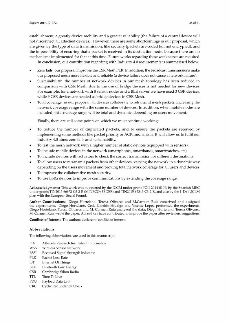
Sensors 2017, 17, 372 28 of 31
establishment, a greatly device mobility and a greater reliability (the failure of a central device willnot disconnect all attached devices). However, there are some shortcomings in our proposal, whichare given by the type of data transmission, like security (packets are coded but not encrypted), andthe impossibility of ensuring that a packet is received in its destination node, because there are nomechanisms implemented for that at this time. Future works regarding these weaknesses are required.
In conclusion, our contribution regarding with Industry 4.0 requirements is summarised below:
• Zero fails: our proposal improves the CSR Mesh PLR. In addition, the broadcast transmissions makeour proposed mesh more flexible and reliable (a device failure does not cause a network failure).
• Sustainability: the number of network devices in our mesh topology has been reduced incomparison with CSR Mesh, due to the use of bridge devices is not needed for new devices.For example, for a network with 8 sensor nodes and a BLE server we have used 3 CSR devices,while 9 CSR devices are needed as bridge devices in CSR Mesh.
• Total coverage: in our proposal, all devices collaborate to retransmit mesh packets, increasing thenetwork coverage range with the same number of devices. In addition, when mobile nodes areincluded, this coverage range will be total and dynamic, depending on users movement.
Finally, there are still some points on which we must continue working:
• To reduce the number of duplicated packets, and to ensure the packets are received byimplementing some methods like packet priority or ACK mechanism. It will allow us to fulfil ourIndustry 4.0 aims: zero fails and sustainability.
• To test the mesh network with a higher number of static devices (equipped with sensors).• To include mobile devices in the network (smartphones, smartbands, smartwatches, etc).• To include devices with actuators to check the correct transmission for different destinations.• To allow users to retransmit packets from other devices, varying the network in a dynamic way
depending on the users movement and proving total network coverage for all users and devices.• To improve the collaborative mesh security.• To use LoRa devices to improve communications by extending the coverage range.
Acknowledgments: This work was supported by the JCCM under grant POII-2014-010P, by the Spanish MECunder grants TIN2015-66972-C5-2-R (MINECO/FEDER) and TIN2015-65845-C3-2-R, and also by the I+D+i UCLMplan with the European Social Found.
Author Contributions: Diego Hortelano, Teresa Olivares and M.Carmen Ruiz conceived and designedthe experiments. Diego Hortelano, Celia Garrido-Hidalgo and Vicente Lopez performed the experiments.Diego Hortelano, Teresa Olivares and M. Carmen Ruiz analyzed the data; Diego Hortelano, Teresa Olivares,M. Carmen Ruiz wrote the paper. All authors have contributed to improve the paper after reviewers suggestions.
Conflicts of Interest: The authors declare no conflict of interest.
Abbreviations
The following abbreviations are used in this manuscript:
I3A Albacete Research Institute of InformaticsWSN Wireless Sensor NetworkRSSI Received Signal Strength IndicatorPLR Packet Loss RateIoT Internet Of ThingsBLE Bluetooth Low EnergyCSR Cambridge Silion RadioTTL Time To LivePDU Payload Data UnitCRC Cyclic Redundancy Check

Sensors 2017, 17, 372 29 of 31
References
1. Albacete Research Institute of Informatics. Available online: http://www.i3a.uclm.es/site/index.php/en(accessed on 9 February 2017).
2. Olivares, T.; Orozoco-Barbosa, L.; Lopez, V.; Pedron, P. WISEVINE: Wireless Sensor Networks applied toVineyards. In Proceedings of the 2nd ACM Workshop on Real-World Wireless Sensor Networks (REALWSN2006), Sweden, 19 June 2006.
3. Olivares, T.; Tirado, P.J.; Royo, F.; Castillo, J.C.; Orozoco-Barbosa, L. IntellBuilding: A wireless sensor networkfor intelligent buildings. In Proceedings of the 4th European Conference on Wireless Sensor Networks(EWSN), Delft, The Netherlands, 29–31 January 2007.
4. Royo, F.; Ortiz, A.M.; Diaz, P.; Olivares, T.; Lopez, V.; Orozoco-Barbosa, L. ROBA, A Role-Based Architecturewith cross-layer services and multichemistry hardware supply. In Proceedings of the InternationalConference on Embedded Wireless Systems and Networks, Bologna, Italy, 30 January–1 February 2008.
5. Diaz, P.; Olivares, T.; Orozoco-Barbosa, L. ATON, A battery-less power supply with dynamic duty cyclefor wireless sensor networks. In Proceedings of the IEEE INFOCOM 2009—IEEE Conference on ComputerCommunications, Rio de Janeiro, Brazil, 19–25 April 2009.
6. Ortiz, A.M.; Olivares, T.; Royo, F.; Diaz, P.; Orozco-Barbosa, L. A cross-layer integration prototype forwireless sensor networks. In Proceedings of the ACM SIGCOMM 2009 Conference on Data Communication,Barcelona, Spain, 16–21 August 2009.
7. Ortiz, A.M.; Royo, F.; Olivares, T.; Castillo, J.C.; Orozco-Barbosa, L.; Marrón, P.J.; Fuzzy-Logic based Routingfor Dense Wireless Sensor Networks. Telecommun. Syst. J. 2013, 52, 2687–2697.
8. Royo, F.; Lopez-Guerrero, M.; Olivares, T.; Orozco-Barbosa, L. A fast network configuration algorithm forTDMA wireless sensor networks. EURASIP J. Wirel. Commun. Netw. 2010, 21–30.
9. Ortiz, A.M.; Royo, F.; Olivares, T.; Castillo, J.C.; Orozco-Barbosa, L. On reactive routing protocols in ZigBeewireless sensor networks. Expert Syst. J. 2014, 31, 154–162.
10. Ortiz, A.M.; Olivares, T.; Royo, F.; Crespi, N.; Orozco-Barbosa, L. Smart Cross-Layer Protocol Integration forEfficiency Wireless Communications. Int. J. Ad Hoc Ubiquitous Comput. 2015, 20, 148–158.
11. Diaz, P.; Royo, F.; Olivares, T.; Ramirez-Mireles, F.; Orozco-Barbosa, L. A Case Study on the Power AwareProtocol Framework for Wireless Sensor Networks. Int. J. Distrib. Sens. Netw. 2013, 9, 1–12.
12. Shashi Prabh, K.; Royo, F.; Tennina, S.; Olivares, T. BANMAC: An opportunistic MAC protocol for reliablecommunications in Body Area Networks. In Proceedings of the 2012 IEEE 8th International Conference onDistributed Computing in Sensor Systems (DCOSS), Hangzhou, China, 16–18 May 2012.
13. Diaz, P.; Olivares, T.; Galindo, R.; Ortiz, A.M.; Royo, F.; Clemente, T. The Ecosense Project: an intelligentenergy management system with a wireless sensor and actor network. In Sustainability in Energy and Buildings;Springer: Berlin/Heidelberg, Germany, 2011; pp. 237–245.
14. Olivares, T.; Royo, F.; Ortiz, A.M. An Experimental Testbed for Smart Cities Applications. In Proceedings ofthe 11th ACM International Symposium on Mobility Management and Wireless Access, Barcelona, Spain,3–8 November 2013 .
15. Borgia, E. The Internet of Things vision: Key features, applications and open issues. Comput. Commun. 2014,54, 1–31.
16. Townsend, K.; Cufí, C.; Davidson, R. Getting Started with Bluetooth Low Energy: Tools and Techniques forLow-Power Networking; Oreilly & Associates: Sebastopol, CA, USA, 2014.
17. Plattform Industrie 4.0. Available online: http://www.plattform-i40.de/I40/Navigation/EN/Home/home.html;jsessionid=D03017A808974684F2F061676466D8E5 (accessed on 28 November 2016).
18. The Industrial Internet: Towards the 4th Industrial Revolution. IoT Now Mag. 2016. Available online:http://www.iot-now.com/2016/10/20/53811-the-industrial-internet-towards-the-4th-industrial-revolution/ (accessed on 15 November 2016).
19. Collotta, M.; Pau, G. Bluetooth for internet of things: A fuzzy approach to improve power management insmart homes. Comput. Electr. Eng. 2015, 44, 137–152.
20. Garrido, C.; Olivares, T.; Lopez, V.; Ruiz, M.C. Architecture proposal for heterogeneous BLE-based sensorand actuator networks for easy management of smart homes. In Proceedings of the International Conferenceon Information Processing in Sensor Networks, Vienna, Austria, 11–14 April 2016.
Sensors 2017, 17, 372 30 of 31
21. Hortelano, D.; Olivares, T.; Ruiz, M.C.; Lopez, V. Improving the BLE mesh transmissions with usercollaboration in smart spaces management. In Proceedings of the International Conference on InformationProcessing in Sensor Networks, Vienna, Austria, 11–14 April 2016.
22. Array of Things. Array of Things Offial Site. Available online: https://arrayofthings.github.io (accessed on10 February 2017).
23. Bronzi, W.; Frank, R.; Castignani, G.; Engel, T. Bluetooth low energy performance and robustness analysisfor inter-vehicular communications. Ad Hoc Netw. 2016, 37, 76–86.
24. Narzt, W.; Mayerhofer, S.; Weichselbaum, O.; Haselbock, S.; Hofler, N. Be-In/Be-Out with BluetoothLow Energy: Implicit Ticketing for Public Transportation Systems. In Proceedings of the IEEE XVIIIInternational Conference on Intelligent Transportation Systems, Las Palmas de Gran Canaria, Spain,15–18 September 2015.
25. Jeong, H.D.J.; Lee, W.; Lim, J.; Hyun, W. Utilizing a bluetooth remote lock system for a smartphone.Pervasive Mob. Comput. 2015, 24, 150–165.
26. Kim, H.S.; Lee, J.Y.; Jang, J.W. Blemesh: A wireless mesh network protocol for bluetooth low energy devices.In Proceedings of the 2015 3rd International Conference on Future Internet of Things and Cloud (FiCloud),Rome, Italy, 24–26 August 2015; pp. 558–563.
27. Zenker, P.; Krug, S.; Binhack, M.; Seitz, J. Evaluation of BLE Mesh capabilities: A case study based onCSRMesh. In Proceedings of the 2016 Eighth International Conference on Ubiquitous and Future Networks(ICUFN), Vienna, Austria, 5–8 July 2016; pp. 790–795.
28. Patti, G.; Leonardi, L.; Lo Bello, L. A Bluetooth Low Energy real-time protocol for Industrial Wireless meshNetworks. In Proceedings of the IECON 2016—42nd Annual Conference of the IEEE Industrial ElectronicsSociety, Florence, Italy, 23–26 October 2016; pp. 4627–4632.
29. Bluetooth SIG. Bluetooth Technology Adding Mesh Networking to Spur New Wave of Innovation.Available online: https://www.bluetooth.com/news/pressreleases/2015/02/24/bluetoothtechnology-adding-mesh-networking-to-spur-new-wave-of-innovation (accessed on 10 February 2017).
30. Bluetooth SIG. Bluetooth Core Specification v 5.0. Available online: https://www.bluetooth.com/specifications/adopted-specifications (accessed on 10 February 2017).
31. Nordic Semiconductor. Nordic Semiconductor Official Site. Available online: https://www.nordicsemi.com(accessed on 10 February 2017).
32. Qualcomm Technologies International, Ltd. and/or Its Affiliated Companies. Cambridge Silicon RadioLimited Offial Site. Available online: http://www.csr.com (accessed on 10 February 2017).
33. Snekvik, T. nRF OpenMesh. Available online: https://github.com/NordicSemiconductor/nRF51-ble-bcast-mesh (accessed on 10 February 2017).
34. Norwegian University of Science and Technology. Norwegian University of Science and Technology OffialSite. Available online: https://www.ntnu.edu/ (accessed on 10 February 2017).
35. Nordic Semiconductor, nRF51 Series SoC. Available online: https://www.nordicsemi.com/eng/Products/nRF51-Series-SoC (accessed on 10 February 2017).
36. Qualcomm Technologies International, Bluetooth Smart csr101x Product Family. Available online:http://www.csr.com/products/bluetooth-smart-csr101x-product-family (accessed on 10 February 2017).
37. Qualcomm Technologies International, Csrmesh. Available online: https://wiki.csr.com/wiki/CSRmesh(accessed on 10 February 2017).
38. ZigBee Alliance. ZigBee Alliance Offial Site. Available online: http://www.zigbee.org (accessed on 10February 2017).
39. Wi-Fi Alliance. Wi-Fi Alliance Offial Site. Available online: http://www.wi-fi.org (accessed on 10February 2017).
40. Subramanian, J.; Morris, R.; Balakrishnan, H. UFlood: High-throughput flooding over wireless meshnetworks. In Proceedings of the 31st Annual IEEE International Conference on Computer Communications,Orlando, FL, USA, 25–30 March 2012; pp. 82–90.
41. Bluetooth SIG. Specification of the Bluetooth System. Covered Core Package Version: 4.0. Available online:https://www.bluetooth.com/specifications/adopted-specifications/legacy-specifications (accessed on10 February 2017).

Sensors 2017, 17, 372 31 of 31
42. Bluetooth SIG. Specification of the bluetooth system. Covered core package version: 4.1. Available online:https://www.bluetooth.com/specifications/adopted-specifications/legacy-specifications (accessed on10 February 2017).
43. Bluetooth SIG. Specification of the Bluetooth System. Covered Core Package Version: 4.2. Available online:https://www.bluetooth.com/specifications/adopted-specifications (accessed on 10 February 2017).
44. The Smart Factory of the Future. Part 1. Available online: http://www.belden.com/blog/industrialethernet/The-Smart-Factory-of-the-Future-Part-1.cfm (accessed on 10 February 2017).
45. The Smart Factory of the Future. Part 2. Available online: http://www.belden.com/blog/industrialethernet/The-Smart-Factory-of-the-Future-Part-2.cfm (accessed on 10 February 2017).
46. Murugesan, S.; Laplante, P.A. It for a greener planet. J. IT Prof. 2011, 13, 16–18.47. Kern, E.; Naumann, S.; Dick, M.; Johann, T.; Guldner, A. Software and gren software engineering-definitions,
measurements and quality aspects in green software engineering. In Proceedings of the First InternationalConference on Information and Communication Technologies for Sustainability, Zurich, Switzerland,14–16 February 2013.
48. Stock, T.; Seliger, G. Opportunities of sustainable manufacturing in industry 4.0. Procedia CIRP 2016, 40,536–541.
49. Jacobsson, M.; Guo, C.; Niemegeers, I. An experimental investigation of optimized flooding protocols usinga wireless sensor network testbed. Comput. Netw. 2011, 55, 2899–2913.
50. Libelium Comunicaciones Distribuidas S.L. Available online: http://www.libelium.com (accessed on10 February 2017).
51. Bluegiga, a Silicon Labs Company. Available online: https://www.bluegiga.com (accessed on 10February 2017).
52. Qualcomm Technologies International, Designing an Inverted-F Antenna. Application Note, 2011.
c© 2017 by the authors; licensee MDPI, Basel, Switzerland. This article is an open accessarticle distributed under the terms and conditions of the Creative Commons Attribution(CC BY) license (http://creativecommons.org/licenses/by/4.0/).