Embed Size (px)
DESCRIPTION
DC/AC 3-Phase Inverter (LTspice Model) Simplified SPICE Behavioral Model Bee Technologies Inc.
Citation preview
DC/AC Inverter (3-Phase) Simplified SPICE Behavioral Model
All Rights Reserved Copyright (C) Bee Technologies Corporation 2011 1
Contents
1. Model Overview
2. Benefit of the Model
3. Concept of the Model
4. 3-Phase DC/AC Specification (Example)
5. Parameter Settings
6. Input-Output Characteristics6.1 Simulation Circuit and Setting
7. Line-to-Line Output Characteristics7.1 Simulation Circuit and Setting
8. Efficiency Characteristics8.1 Simulation Circuit and Setting
9. Minimum DC Input Voltage9.1 Simulation Circuit and Setting
Library Files and Symbol Files Location
Simulation Index
All Rights Reserved Copyright (C) Bee Technologies Corporation 2011 2
1.Model Overview
All Rights Reserved Copyright (C) Bee Technologies Corporation 2011 3
• This 3-Phase DC/AC Inverter Simplified SPICE Behavioral Model is for users who require the model of an Inverter as a part of their system.
• The model focuses on the input/output relationships of the Inverter block; therefore, it is not using high frequency models (e.g. oscillator and noise models), and is not based on the electronic topologies of the Inverter.
• The model enables long-term behavior simulation of the system (e.g. in a Photovoltaic system simulation).
2.Benefit of the Model
• Enable Transient Simulation.
• Can be adjusted to your own 3-Phase DC/AC specifications, by editing the
model parameters.
• The simplified model is an easy-to-use, which can be provided without the
circuit detail.
• Time and costs are saved because only the necessary parts are simulated.
All Rights Reserved Copyright (C) Bee Technologies Corporation 2011 4
3.Concept of the Model
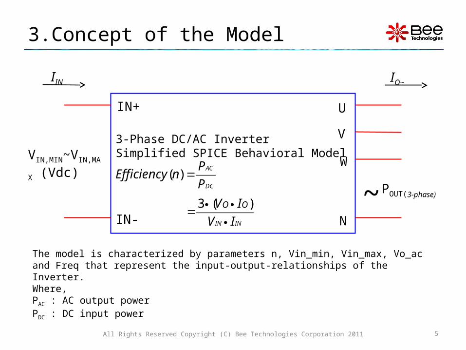
The model is characterized by parameters n, Vin_min, Vin_max, Vo_ac and Freq that represent the input-output-relationships of the Inverter. Where,
PAC : AC output powerPDC : DC input power
All Rights Reserved Copyright (C) Bee Technologies Corporation 2011 5
3-Phase DC/AC Inverter Simplified SPICE Behavioral Model
IN+
IN-
U
N
VIN,MIN~VIN,MAX (Vdc)
IIN IO~
~
V
W
DC
AC
P
PnEfficiency )(
ININ IV
IV OO
)(3POUT(3-phase)

4.DC/AC Specification (Example)
3-Phase DC/AC Inverter with •VIN = 24~250Vdc, •VO, LN = 100VAC, •POUT(3-phase) = 1500W,•and Efficiency = 80%
All Rights Reserved Copyright (C) Bee Technologies Corporation 2011 6
3-Phase DC/AC InverterEfficiency (n) = 80%
Operating Input Voltage:VIN,MIN=24 ~ VIN,MAX =250(Vdc)
IN+
IN-
~ POUT(3-phase)
IO~IIN
U
N
V
W

5.Parameter Settings (Example)
VIN_MIN DC minimum input voltage• 0 < VIN_MIN < VIN_MAX• Value = 24V
VIN_MAX DC maximum input voltage• VIN_MAX > VIN_MIN• Value = 250V
VO_AC AC Output Voltage, rms value• e.g. 100V, 220V• Value = 100V
FREQ AC Output Frequency• e.g. 50Hz, 60Hz• Value = 50Hz
N Efficiency in 100%• 0 < N < 1• Value = 0.8 (80% Efficiency)
• From the inverter specification, the model is characterized by setting parameters VIN_MIN, VIN_MAX, VO_AC, FREQ, and N.
All Rights Reserved Copyright (C) Bee Technologies Corporation 2011 7
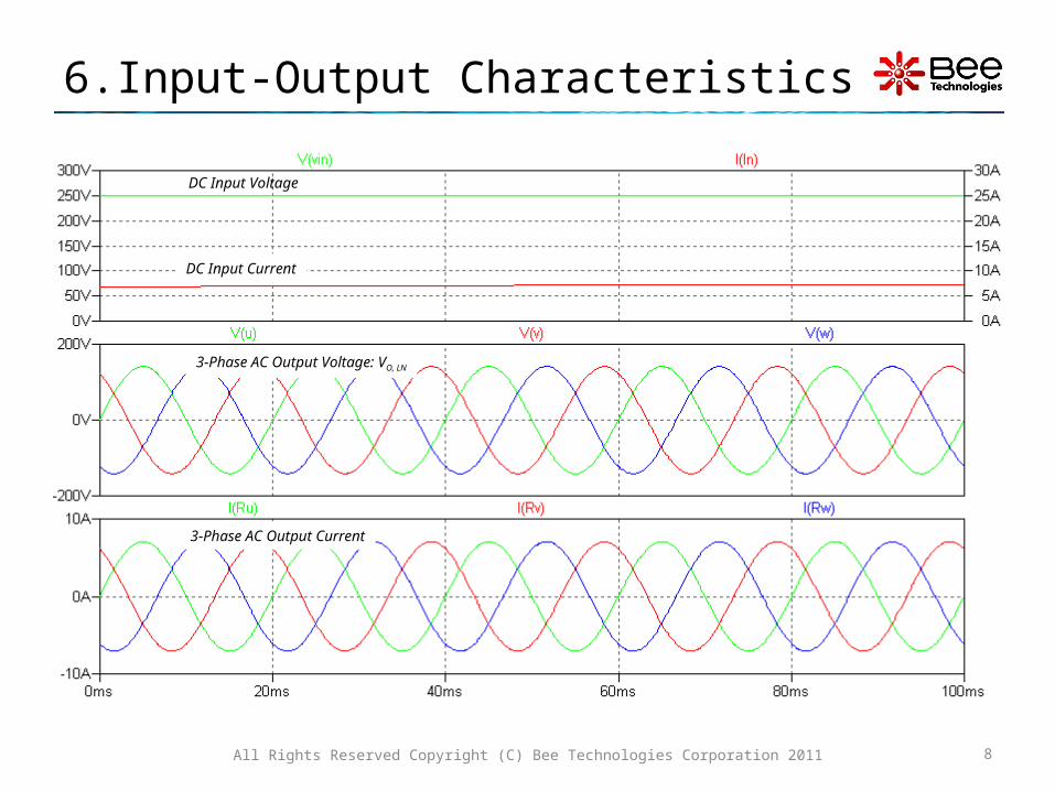
6.Input-Output Characteristics
All Rights Reserved Copyright (C) Bee Technologies Corporation 2011 8
3-Phase AC Output Voltage: VO, LN
DC Input Current
DC Input Voltage
3-Phase AC Output Current
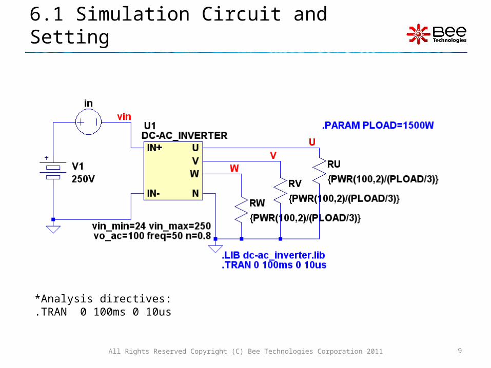
6.1 Simulation Circuit and Setting
*Analysis directives: .TRAN 0 100ms 0 10us
All Rights Reserved Copyright (C) Bee Technologies Corporation 2011 9
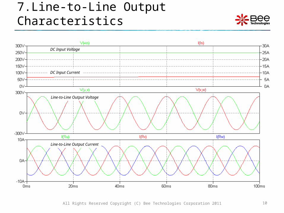
7.Line-to-Line Output Characteristics
All Rights Reserved Copyright (C) Bee Technologies Corporation 2011 10
Line-to-Line Output Current
Line-to-Line Output Voltage
DC Input Voltage
DC Input Current

7.1 Simulation Circuit and Setting
*Analysis directives: .TRAN 0 100ms 0 10us
All Rights Reserved Copyright (C) Bee Technologies Corporation 2011 11

8.Efficiency Characteristics
Output and efficiency of the Inverter on time domain analysis.Efficiency(n) = PAC/PDC Efficiency = (3*VO(RMS)*IO(RMS)/VIN*IIN)*100, where the output voltage (VO(RMS)) is the inverter spec and the output current (IO(RMS)) is read from the simulation result.
All Rights Reserved Copyright (C) Bee Technologies Corporation 2011 12
N = 0.8 Hold the Ctrl key and left click to Calculate RMS value of I(Ru)
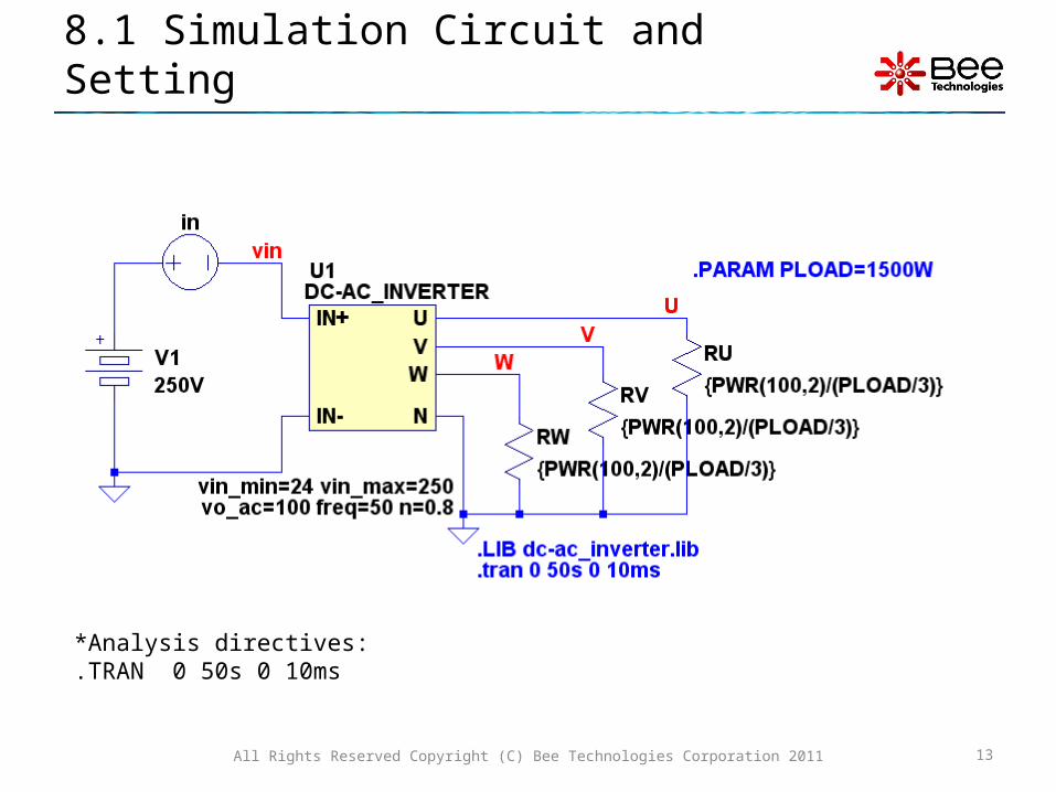
8.1 Simulation Circuit and Setting
*Analysis directives: .TRAN 0 50s 0 10ms
All Rights Reserved Copyright (C) Bee Technologies Corporation 2011 13
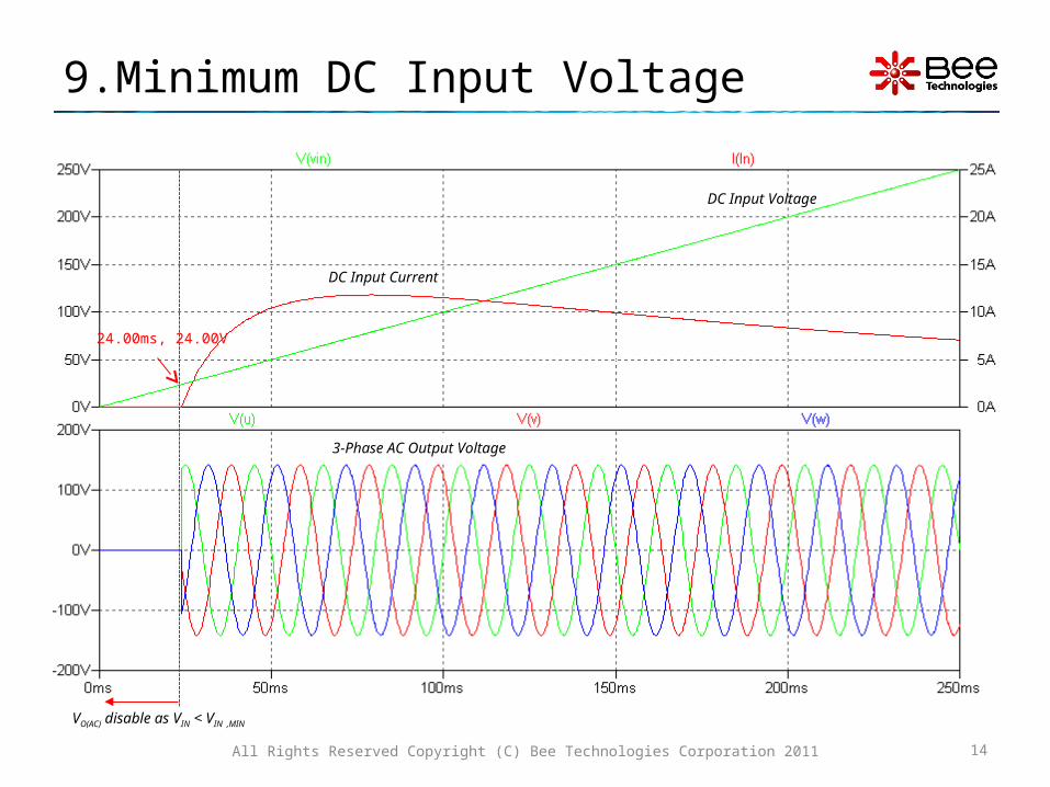
9.Minimum DC Input Voltage
All Rights Reserved Copyright (C) Bee Technologies Corporation 2011 14
VO(AC) disable as VIN < VIN ,MIN
3-Phase AC Output Voltage
DC Input Voltage
DC Input Current
24.00ms, 24.00V

9.1 Simulation Circuit and Setting
*Analysis directives: .TRAN 0 250ms 0 10u
All Rights Reserved Copyright (C) Bee Technologies Corporation 2011 15

Library Files and Symbol Files Location
1) Copy LIB files from CD to C:\Program Files\LTC\LTspiceIV\lib\sub
2) Copy LTspice symbols files from CD to C:\Program Files\LTC\LTspiceIV\lib\sym
All Rights Reserved Copyright (C) Bee Technologies Corporation 2011 16
.LIB
.ASY

Simulation Index
All Rights Reserved Copyright (C) Bee Technologies Corporation 2011 17
Simulations Folder name
1. Input-Output Characteristics.............................................
2. Line-to-Line Output Characteristics..................................
3. Efficiency Characteristics.................................................
4. Minimum DC Input
Voltage...............................................
VO_LN
VO_LL
Efficiency
VIN_MIN