Embed Size (px)
Citation preview
Page | 1
Contents
OSI Model
TCP/IP
Telnet, FTP and TFTP
HDLC
IP Addressing and Subnetting
Cisco IOS
CDP
Router commands
Routing Protocols
EIGRP
OSPF
Routed protocol: Frame-Relay
Access-Lists
NAT
Switching
STP
VLANs
VTP
Security
Miscellaneous
Network Devices
WAN Devices
Wireless LAN
Others
Page | 2
OSI Model
The 7 layers of OSI model are:
1. The Application Layer: Application layer is responsible for identifying and establishing the availability of desired communication
partner and verifying sufficient resources exist for communication. Some of the important application layer protocols are: WWW,
SMTP, FTP, etc.
2. The Presentation Layer: This layer is responsible for presenting the data in standard formats. This layer is responsible for data
compression, decompression, encryption, and decryption. Some Presentation Layer standards are: JPEG, MPEG, MIDI, PICT, Quick
Time, TIFF.
3. The Session Layer: Session Layer is responsible for co-ordinating communication between systems/nodes. The following are
some of the session layer protocols and interfaces: a) Network File System (NFS), SQL, RPC (Remote Procedure Call), X-Windows,
ASP, DNA SCP.
4. The Transport Layer: The Transport Layer is responsible for multiplexing upper-layer applications, session establishment, and
tearing-down of virtual circuits. This layer is responsible for flow control, to maintain data integrity.
5. The Network Layer: There can be several paths to send a packet from a given source to a destination. The primary responsibility
of Network layer is to send packets from the source network to the destination network using a pre-determined routing methods.
Routers work at Network layer.
6. The Data Link Layer:
Data Link Layer is layer 2 of OSI reference model. This layer is divided into two sub-layers:
A. Logical Link Control (LLC) sub-layer.
B. Media Access Control (MAC) sub-layer.
The LLC sub-layer handles error control, flow control, framing, and MAC sub-layer addressing.
The MAC sub-layer is the lower of the two sub-layers of the Data Link layer. MAC sub-layer handles access to shared media, such a
Token passing or Ethernet.
7. Physical Layer: The actual flow of signals take place through Physical layer. At Physical layer, the interface between the DTE and
DCE is determined. The following are some of the standard interfaces are defined at Physical layer: EIA/TIA-232, EIA/TIA-
449,V.24,V.35,X.21,G.703,HSSI (High Speed Serial Interface).
SONET defines interface standards at the physical layer of the OSI seven-layer model. The standard defines a hierarchy of
interface rates that allow data streams at different rates to be multiplexed. SONET establishes Optical Carrier (OC) levels from 51.8
Mbps (OC-1) to 9.95 Gbps (OC-192).
Page | 3
TCP/IP
1. Port numbers are used by TCP/ UDP to set up sessions with other hosts. The following are the recommended port numbers:
1. Numbers 0 - 255 are used for public applications.
2. Numbers 255 - 1023 are assigned to companies so that they can use these port numbers in their applications.
3. Numbers above 1023 are used by upper layers to set up sessions with other hosts and by TCP to use as source and destination
addresses.
2.The term Segments is usually associated with Transport layer
The term Packets is usually associated with Network Layer and
The term Frames is usually associated with Data Link Layer
3. TCP: TCP is a full-duplex, connection-oriented protocol. It incorporates error checking as well.
UDP (User Datagram Protocol): UDP is a thin protocol. UDP is a connectionless protocol. It doesn't contact the destination before
sending the packet and doesn't care whether the packet is reached at the destination.
4. SNMP is part of TCP/IP protocol suite. It allows you to monitor and manage a network from a centralized place by using SNMP
Manager software. The systems or devices that provide the responses are called agents (or MIBs). An SNMP agent is any computer
running SNMP agent software.
MIB stands for Management Information Base. It is part of SNMP agent database. A MIB records and stores information about the
host it is running on. An SNMP manager can request and collect information from an agent's MIB. Routers are typical MIB agents.
SNMP agent generates "trap" messages that are then sent to an SNMP management console, which is a trap destination.
Telnet, FTP, and TFTP:
1. Telnet is used for terminal emulation that runs programs remotely. Telnet uses TCP/IP protocol.
2. Telnet requires a username and password to access.
3. FTP (File Transfer Protocol) is a connection oriented protocol. It uses TCP/IP for file transfer. Compare this with TFTP (Trivial File
Transfer Protocol) that uses UDP (Connectionless protocol). SNMP uses UDP over IP. Tracert, Ping uses ICMP as their base protocol.
FTP is used to transfer files.
Both FTP and Telnet are client-server protocols. Note that TCP/IP is a client server oriented protocol.
HDLC
1. The High Level Data Link Control protocol (HDLC) is the default encapsulation used on the synchronous serial interfaces of a
Cisco router. HDLC is a Data Link layer protocol used to encapsulate and transmit packets over point-to-point links.
Page | 4
Internetwork IP addressing and Subnetting:
1. IP addresses are written using decimal numbers separated by decimal points. This is called dotted decimal notation of expressing
IP addresses.
The different classes of IP addresses are as below:
Class Format Leading Bit pattern Network address Range Maximum networks Maximum hosts/ nodes
A N.H.H.H 0 0-126 127 16,777,214
B N.N.H.H 10 128-191 16,384 65,534
C N.N.N.H 110 192 -223 2,097,152 254
- Network address of all zeros means "This network or segment".
- Network address of all 1s means "all networks", same as hexadecimal of all Fs.
- Network number 127 is reserved for loop-back tests.
- Host (Node) address of all zeros mean "This Host (Node)".
- Host (Node) address of all 1s mean "all Hosts (Nodes)" on the specified network.
2. The range of numbers from 224.0.0.0 to 239.255.255.255 is used for multicast packets. This is known as Class D address range.
3. Subnetting is nothing but creating networks within a network. Subnetting allows an organization with a single IP address (Class
A /Class B /Class C) to have multiple subnetworks, thus allowing several physical networks within the organization.
4. How to maximize the number of subnets for a given number of hosts:
Let us take a network ID of 168.8.0.0, and find the maximum number of possible subnets and the corresponding subnet mask that
can accommodate at least 500 hosts. The steps involved are outlined below:
I. Find the Class of the IP address, in this case it is a class B network. Class B network has the form N.N.H.H. Therefore, we have a
total of 16 bits (two octets) for assigning to internal networks and hosts. The minimum number of host addresses required is 500.
The last octet corresponds to 2^8 = 256 hosts which is still less than 500 Hosts. Therefore, you have to borrow one more bit from
the third octet to make it 256*2 = 512 Hosts. This leaves 7 bits in the third octet for assigning subnet addresses. This is equal to
2^7=128 subnets.
II. Write the 7 bits available for subnetting in third octet in the form 11111110 (last bit being the Host bit). The decimal
equivalent of the first seven bits is 2^7+2^6+2^5+2^4+2^3+2^2+2^1 = 128 + 64 +32 + 16 + 8 + 4 + 2 = 254.
III. Therefore, the subnet mask required is 255.255.254.0.
5. How to maximize the number of hosts for a given number of subnets:
Determining the subnet mask that allows maximum number of hosts:
Let us consider an IP address 196.202.56.0 with four subnets and maximize the number of host for the given subnets. The steps
involved are as below:
I. The number of subnets required are four. We need to add subnets of all ones and all zeros to this. This is because all zeros and
all ones subnets belong to "this subnet" and "all subnets" broadcasts and cannot be used. Therefore, the total number of subnets to
be reserved is 4+2 = 6.
II. We want to implement maximum possible Hosts. Therefore, we need to minimize the number of subnets. This minimum
number is 6 here. If we reserve 2 bits, it results in only 2^2=4 subnets which is less than 6. Therefore, we have to reserve 3 bits for
Page | 5
implementing subnets, resulting in 2^3=8 subnets. This is now optimized for maximum number of Hosts (as we have optimized for
minimum number of subnets).
III. Write the 3 bits available for subnetting in fourth octet in the form 11100000 (Five 0s being Host bits). The decimal equivalent
is 2^7+2^6+2^5
= 128 + 64 +32 = 224.
IV. Therefore, the subnet mask required is 255.255.255.224.
6. 127.0.0.1 is the local loop back address.
7. In an internetwork, the number of distinct IPs' required are
1. One each per client computer
2. One each per server computer
3. One each per router interface
For example, your network has 2 servers, 26 clients machines, and 2 router interfaces the total number of IP addresses required are
30.
8. Finding the number of Hosts and subnets available for a given subnet mask: For example, let us find the number of hosts and
subnets available for an IP 156.233.42.56 with a subnet mask of 7 bits.
a. Class B network has the form N.N.H.H, the default subnet mask is 16 bits long. There is additional subnet mask of 7 bits long.
b. 7 bits of subnet mask corresponds to (2^7-2)=128-2 = 126 subnets.
c. 9 bits (16-7) of host addresses corresponds to (2^9-2)=512-2 = 510 hosts.
Sometimes, the subnet mask is specified with the bits available in the default subnet mask. In this case the bits available in default
subnet mask is 16. Therefore, total number of bits available in the subnet mask are 16+7=23. If you are given a subnet mask of 23
bits long for a class B address, it is understood that it contains the bits from the default subnet mask as well.
Hence, 126 subnets and 510 hosts are available.
9. The directed broadcast should reach all Hosts on the intended network (or subnet, if sub netted). For example, the directed
broadcast address for an IP network 196.233.24.15 with default subnet mask is 196.233.24.255. This is arrived by putting all 1s for
the host potion of the IP address.
10. To find valid hosts given an IP address (say 156.16.3.52) and a subnet mask (sat a 12-bit subnet). The valid hosts are
determined as below:
A 12-bit subnet mask gives us 255.255.255.240; 4094 subnets, each with 14 hosts. (Host addresses of all zeros and all 1s can't be
assigned). The 156.16.3.52 is in the 48 subnet range. The valid range is through 49 - 62. 63 is a broadcast address.
Here is how you get the subnet range:
1. Find the subnet mask. In this case, default subnet mask for Class B address is 255.255.0.0. There are additional; 12 bits in the
subnet mask. Now the subnet mask looks like:
11111111.11111111.11111111.11110000. This is equal to 255.255.255.240.0.2. Now, deduct the lowest value octet (Which is
non zero), from 256. Here, (256-240) =16.
This is the value that the subnets are incremented. Therefore, you will have hosts with values from:
156.16.3.1 to 156.16.3.14 (All 0s and all 1s host addresses cannot be used)
156.16.3.17 to 156.16.3.30
156.16.3.33 to 156.16.3.46

Page | 6
156.16.3.49 to 156.16.3.62 and so on.
It is important to know that subnets are incrementing here by a factor of 16.
11. VLSM (Variable Length Subnet Masking) allows efficient use of IP addresses. Networks implemented with VLSM can be
summarized more efficiently due to manual control. With a distance vector protocol such as RIP or IGRP, only one subnet mask
value can be used on a network, as subnet mask values are not sent in routing updates.
Page | 7
Cisco IOS
1. Cisco router boot configuration commands:
1. boot system - This is a global command that allows you to specify the source of the IOS software image to load. If you configure
more than one source, attempts are made to load the IOS from the first command in the configuration to the last successively. If
the first fails, the second boot command is used.
2. boot system rom - Loads IOS from ROM.
3. boot system flash - Loads the first file from flash memory.
4. boot system tftp <file name> < tftp_address > - Loads IOS with a filename <file name> from a TFTP server.
2. To enable the Cisco IOS to forward packets destined for obscure subnets of directly connected networks onto the best route,
you use "ip classless" command.
3. Internal memory components of a Cisco router:
1. ROM (Read Only Memory): Memory containing micro-code for basic functions to start and maintain the router. ROM is not
typically used after the IOS is loaded.
2. RAM/DRAM : stores the running configuration, routing tables, and packet buffers. Some routers, such as the 2500 series, run IOS
from Flash, not RAM.
3. NVRAM (Non-Volatile Ram): Memory that does not lose information when power is lost. Stores the system’s configuration file
and the configuration register. NVRAM uses a battery to maintain the data when power is turned off.
4. Flash Memory: Stores the compressed IOS (IOS stands for Cisco Internetwork Operating System) image. Flash memory is either
EEPROM or PCMCIA card. Flash memory enables you to copy multiple versions of IOS software. This allows you to load a new level
of the operating system in every router in your network and then, to upgrade the whole network to that version at an appropriate
time.
4. The Cisco router can be configured from many locations.
1. Console port: During the initial installation, you configure the router from a console terminal connected to the "Console port" of
the router.
2. Virtual Terminals (vty): A virtual terminal (vty) is typically accessed through Telnet. A router can be accessed through vty after it
the initial installation in the network. There are five virtual terminals, namely, vty0, vty1, vty2, vty3, vty4.
3. Auxiliary Port: you can configure a router through auxiliary port. Typically, a modem is used to configure the modem through
aux port.
4. TFTP Server: Configuration information can be downloaded from a TFTP server over the network.
5. NMS (Network Management Station): You can also manage router configuration through NMS such as CiscoWorks or HP Open
View.
5. Router modes of operation:
1. User EXEC mode (Prompt: Router>):- This is the LOWEST level of access. This allows examination of router status, see routing
tables, and do some diagnostics. However, you cannot change the router configuration, view the configuration files, or control
Page | 8
the router in any way. The prompt in this mode is "Router>".
2. Privileged (enable) EXEC mode (Prompt: Router#):- This mode allows you to have all the privileges of EXEC (user) mode plus
commands that enable you to view configuration files, change the router configuration, perform troubleshooting that could
potentially disrupt traffic. The default prompt for this mode is "Router#".When you are working in the privileged mode (at #
prompt), you can get back to user mode by typing "disable" at the "#" prompt.
3. Global Configuration mode (Prompt: Router (Config)#):- Global configuration mode allows you to perform tasks that affect the
entire router, such as naming the router, configuration of banner messages, enabling routed protocols, and generally anything
that affects the operation of the entire router.
When you first switch on a router, you enter Setup mode. Setup mode is different from configuration mode in that setup mode
appears when there is no configuration file present. Upon entering setup mode, you can supply some basic configuration
parameters to Cisco router.
6. There are three ways a router learns how to forward a packet:
1. Static Routes - Configured by the administrator manually. The administrator must also update the table manually every time a
change to the network takes place. Static routes are commonly used when routing from a network to a stub (a network with a
single route) network
The command is
ip route network mask address/interface [distance]
ex: ip route 165.44.34.0 255.255.255.0 165.44.56.5
Here, 165.44.34.0 is the destination network or subnet
255.255.255.0 is the subnet mask
165.44.56.5 is the default gateway
2. Default Routes - The default route (gateway of last resort) is used when a route is not known or is infeasible. The command is
ip route 0.0.0.0 0.0.0.0 165.44.56.
The default gateway is set to 165.44.56.5
3. Dynamic Routes - In dynamic routing, the routing tables are automatically updated. Dynamic routing uses broadcasts and
multicasts to communicate with other routers.
The commands to enable rip are:
router rip
network <major network number>
7. The following are some important commands that can be used to edit and review command history buffer on a Cisco router. It
will be useful to practice these commands.
<ctrl> A: Move to the beginning of the command line
<ctrl> E: Move to the end of the command line
<ctrl> F: Move forward one character, same as using "Right Arrow".
<ctrl> B: Move backward one character, same as using "Left Arrow".
<ctrl> P: Repeat Previous command, same as using "Up Arrow".
<ctrl> N: Repeat Next (more recent) command, same as using "Down Arrow".
<esc> B: Moves to beginning of previous word.
Page | 9
<esc> F: Moves to beginning of next word.
<ctrl>R: Creates new command prompt, followed by all the characters typed at the last one.
8. There are five different types of passwords:
1. ENABLE PASSWORD - A global command that restricts access to privileged exec mode. This is a non-encrypted password.
2. ENABLE SECRET - Assigns a one-way encryptographic secret password, available in versions 10.3 and up. This secret password is
used instead of the enable password when it exists.
3. Virtual Terminal Password (vty password) - The virtual terminal password is used for Telnet sessions into the router. The
password can be changed at any time. It can be set up when you configure the router from the console. There can be five distinct
passwords corresponding to each vty (vty0 to vty4) or there can be a single password for all vtys.
4. Auxiliary Password - Auxiliary password is used to set password to the auxiliary port. This port is used to access a router through
a modem.
5. Console Password - Console password is used to set the console port password
9. The Catalyst IOS software is very similar to a router IOS. IOS image files are stored in the Flash memory on a switch.
Show running-config [interface <type> <mod>/<num> | vlan <vlan-id> | module <mod>]: The command displays the contents of
the configuration file.
Show tech-support: The command is primarily used to send switch information to Cisco TAC support personnel.
Verify flash:<filename> - This command is used to verify whether the Flash contents are intact, and not corrupted. The checksum of
the flashfile specified is verified for correctness.
10. By default, Cisco routers support 5 simultaneous telnet sessions. This number can be configured using IOS commands.
11. Routers can make alternate route decisions based on ICMP messages, if appropriate. Routers send an ICMP message if the
destination is unreachable.
ICMP (Internet Message Control Protocol) messages are used for basic error reporting between host to host, or host to gateway. It
is not used for error reporting between Gateways. ICMP messages are encapsulated using the IP protocol. For example, the
command “ping” uses ICMP protocol. In the OSI Reference model, ICMPs are generally considered part of the IP layer.
CDP
1. CDP stands for Cisco Discovery Protocol. This protocol is proprietary of Cisco. CDP runs SNAP (Sub network Access Protocol) at
the Data Link Layer. Two Cisco devices running two different Network layer protocol can still communicate and learn about each
other.
2. The following are true about CDP:
1. CDP - Cisco Discovery Protocol is a Cisco proprietary Layer 2 protocol.
2. CDP uses a multicast packet to the common destination address 01-00-0c-cc-cc.
3. CDP packets are sent out with a non-zero TTL after an interface is enabled and with a zero TTL value immediately before and
interface is made idle. This enables the neighboring devices to quickly discover the state of neighbors.
Page | 10
4. CDP packets will never be forwarded beyond the directly connected devices. To find CDP information on indirectly connected
routers, administrators can 'telnet' to the intended destination device and run CDP command.
Router Commands
1. The following are some frequently used COPY commands:
1. COPY RUNNING-CONFIGURATION STARTUP-CONFIGURATION (alternatively, you can use an older version of the command,
WRITE MEMORY): This command saves the current configuration to NVRAM. Alternatively, we can issue the command using short
form: COPY RUNNING STARTUP - Copies configuration from RAM to NVRAM
2. COPY STARTUP RUNNING - This command merges configuration from NVRAM to RAM.
3. COPY FLASH TFTP - Copies current IOS from router flash memory to TFTP server.
4. COPY TFTP FLASH - Copies image file from TFTP server to flash. This is used to upgrade the IOS image file to a newer version, or
if your IOS image becomes corrupt.
2. SHOW command is extensively used for seeing the status and configuration information of the router.
Some of the frequently used commands are:
1. SHOW RUNNING-CONFIGURATION -This command displays the router's active configuration file, passwords, system name, and
interface settings, interfaces IP addresses etc.
2. SHOW INTERFACE - Shows status and configuration information of the local interfaces. The first line says something like
“TokenRing1 is up, line protocol is up”. The first part “TokenRing1 is up” describes the physical layer components such as electrical
cabling and signaling are OK. The second part “line protocol is up” means that the router is detecting keep-alive messages. The
router may be put into administratively down status, at which point the line would read, “TokenRing1 is administratively down , line
protocol is down.”
3. SHOW INTERFACE SERIAL 0 - Shows the serial 0 configuration.
4. SHOW INTERFACES - Displays statistics for all interfaces configured on the switch.
5. SHOW PROCESS - Displays a router’s CPU utilization.
6. SHOW CONFIG - Displays information on the startup configuration.
7. SHOW VERSION - Displays information about the system hardware (RAM/ROM), software version, names of configuration files,
and boot-images. This command will also show the current configuration register value.
3. Show IP protocol: This command will show information on RIP timers including routing update timer (30sec default), hold-down
timer (default 180sec). It also displays the number of seconds due for next update (this is fraction of update timer). This command
also gives the network number for which IP RIP is enabled, Gateway, and the default metric.
4. Show IP route: This command will display the IP routing table entries. In addition, it displays the Gateway of last resort (if one is
assigned). It also displays the codes used for various types of routes. Some of the important codes are:
C: directly connected;
S: Statically connected
I: IGRP
R: RIP
Page | 11
Show IP interface: This command shows you interface-wise information such as IP address assigned to each interface, whether the
interface is up, MTU etc.
Debug IP RIP: Debug IP RIP will turn the RIP debugging ON. This will display a continuous list of routing updates as they are sent
and received. This leads to lot of overhead, which is the reason that you use "undebug ip rip" to turn-off debugging as soon as you
finish with debugging.
5. The banner is displayed whenever anyone logs in to your Cisco router. The syntax is
"banner motd # ". MOTD stands for "Message Of The Day".
# symbol signifies the start of the banner message to the router. You will be prompted for the message to be displayed. You need
to enter "#" symbol at the end of the message, signifying that the message has ended.
6. Copy running-config startup-config
-allows the running configuration file to be saved onto the startup configuration file on the switch. Make sure that you use this
command whenever you have made any configuration changes to the switch. Otherwise, your configuration command are not
permanently saved in the switch memory, and lost soon after power cycling the switch.
The command:
Copy startup-config running-config
-allows startup configuration file to be copied into the current running configuration file.
Copy running-config tftp:
-Copies the running configuration of a switch to a TFTP server. You will be prompted for the server address and destination
filename.
Copy tftp: startup-config
-This command is useful to restore the startup-config file incase the original is lost or corrupt. The command loads the startup-
config file from a remote tftp server.
Page | 12
Routing Protocols
Classful routing protocols:
RIP v1, IGRP are examples of classful routing protocols. It is important to know that classful routing protocols do not exchange
subnet information during routing information exchanges. The summarization is always done automatically at major network
boundaries.
Classless routing protocols: RIP v2, EIGRP, OSPF, BGP v4, and IS-IS are examples of classless routing protocols. In classless routing
protocols, subnet information is exchanged during routing updates. This results in more efficient utilization of IP addresses. The
summarization in classless networks is manually controlled.
Maximum hop count supported by RIP is 15.
Routed and Routing Protocols
Routing protocols job is to maintain routing tables and route packets appropriately. Examples of routing protocols are RIP, IGRP,
EIGRP, OSPF. Routers can support multiple independent routing protocols and can update and maintain routing tables for each
protocol independently.
Routed protocols are used to transport user traffic from source node to destination node. Examples of routed protocols are IP, IPX,
and AppleTalk.
There are broadly three types of routing protocols:
1. Distance Vector (Number of hops) - Distance vector routing determines the direction (vector) and distance to any link in the
internetwork. Typically, the smaller the metric, the better the path. EX: Examples of distance vector protocols are RIP and IGRP.
Distance vector routing is useful for smaller networks. The limitation is that any route which is greater than 15 hops is considered
unreachable. Distance vector protocols listen to second hand information to learn routing tables whereas, Link state protocols
build routing tables from first-hand information. Routers with distance vector protocols send its entire routing table to each of its
adjacent neighbors.
2. Link State Routing: Link State algorithms are also known as Shortest Path First (SPF) algorithms. SPF generates the exact topology
of the entire network for route computation, by listening to the first-hand information. Link State protocols take bandwidth into
account using a cost metric. Link State protocols only send updates when a change occurs, which makes them more efficient for
larger networks. Bandwidth and delay are the most widely used metrics when using Link-State protocols. EX: OSPF and NLSP.
Benefits of Link State protocols:
1. Allows for a larger scalable network
2. Reduces convergence time
3. Allows “supernetting”
The metric limit for link-state protocols is 65,533
Page | 13
3. Balanced Hybrid - Balanced Hybrid combines some aspects of Link State and Distance Vector routing protocols.
Balanced Hybrid uses distance vectors with more accurate metrics to determine the best paths to destination networks. Ex: EIGRP
Distance vector protocol depends only on Hop count to determine the nearest next hop for forwarding a packet.
One obvious disadvantage is that, if you have a destination connected through two hops via T1 lines, and if the same destination
is also connected through a single hop through a 64KBPS line, RIP assumes that the link through 64KBPS is the best path!
RIP (and IGRP) always summarizes routing information by major network numbers. This is called classful routing.
RIP, RIP2, and IGRP use distance vector algorithms.
RIP2 transmits the subnet mask with each route. This feature allows VLSM (Variable Length Subnet Masks) by passing the mask
along with each route so that the subnet is exactly defined.
IP RIP based networks send the complete routing table during update. The default update interval is 30 seconds. IGRP update
packet is sent every 90 seconds by default.
Default administrative distances some important routing protocols are as below:
Route Source Default Distance
Directly connect Interface 0
Static Route 1
IGRP 100
RIP 120
Unknown 255
An administrative distance of 0 represents highest trustworthiness of the route.
An administrative distance of 255 represents the lowest trustworthiness of the route.
The port numbers used by different programs are as below:
I. FTP: Port #21
II. Telnet: Port #23
III. SMTP: Port #25
IV. SNMP: Port #161
It is important to know that FTP, Telnet, SMTP uses TCP; whereas TFTP, SNMP use UDP.
Address Resolution Protocol (ARP)
ARP is used to resolve or map a known IP address to a MAC sub layer address to allow communication on a multi-access medium
such as Ethernet. Reverse ARP (RARP) is used to obtain an IP address using an RARP broadcast. RARP can be used to boot diskless
workstations over a network.
EIGRP1
Some of the important terms used in Enhanced IGRP are:
Page | 14
1. Successor: A route (or routes) selected as the primary route(s) used to transport packets to reach destination. Note that successor
entries are kept in the routing table of the router.
2. Feasible successor: A route (or routes) selected as backup route(s) used to transport packets to reach destination. Note that
feasible successor entries are kept in the topology table of a router. There can be up to 6 (six) feasible successors for IOS version
11.0 or later. The default is 4 feasible successors.
3. DUAL (Diffusing Update Algorithm): Enhanced IGRP uses DUAL algorithm to calculate the best route to a destination.
Routing metrics used by IGRP:
Bandwidth, MTU, Reliability, Delay, and Load.
1. Bandwidth: This is represents the maximum throughput of a link.
2. MTU (Maximum Transmission Unit): This is the maximum message length that is acceptable to all links on the path. The larger
MTU means faster transmission of packets.
3. Reliability: This is a measurement of reliability of a network link. It is assigned by the administrator or can be calculated by using
protocol statistics.
4. Delay: This is affected by the band width and queuing delay.
5. Load: Load is based among many things, CPU usage, packets processed per sec.
For IGRP routing
You need to provide the AS (Autonomous System) number in the command. Routers need AS number to exchange routing
information. Routers belonging to same AS exchange routing information. OSPF, and IGRP use AS numbers.
OSPF
1. OSPF is a link state technology that uses Dijkstra algorithm to compute routing information. It has the following advantages over
Distance Vector protocols such as RIP:
1. Faster convergence: OSPF network converges faster because routing changes are flooded immediately and computer in
parallel.
2. Support for VLSM: OSPF supports VLSM. However, please note that RIP version2 also supports VLSM.
3. Network Reachability: RIP networks are limited to 15 hops. Therefore, networks with more than 15 hops cannot be reached by
RIP by normal means. On the other hand, OSPF has practically no reachability limitation.
4. Metric: RIP uses only hop count for making routing decisions. This may lead to severe problems in some cases, for example, that
a route is nearer but is very slow compared to another route with plenty of bandwidth available. OSPF uses "cost" metric to choose
best path. Cisco uses "bandwidth" as metric to choose best route.
5. Efficiency: RIP uses routing updates every 30 seconds. OSPF multicasts link-state updates and sends the updates only when there
is a change in the network.
Page | 15
2. An OSPF area is a collection of networks and routers that have the same area identification. OSPF process identifier is locally
significant.
Two neighboring router interfaces can have same or different process ids. It is required to identify a unique instance of OSPF
database.
3. OSPF keeps up to six equal-cost route entries in the routing table for load balancing. Further, OSPF uses Dijkstra algorithm to
calculate lowest cost route.
The algorithm adds up the total costs between the local router and each destination network. The lowest cost route is always
preferred when there are multiple paths to a given destination.
4. OSPF determines the router ID using the following criteria:
1. Use the address configured by the ospf router-id command
2. Use the highest numbered IP address of a loopback interface
3. Use the highest IP address of any physical interface
4. If no interface exists, set the router-ID to 0.0.0.0
If no OSPF router ID is explicitly configured, OSPF computes the router-ID based on the items 2, 3, and 4 and restarts OSPF (if the
process is enabled and router-ID has changed).
5. When two or more routers are contending to be a DR (designated Router) on a network segment, the router with the highest
OSPF priority will become the DR for that segment. The same process is repeated for the BDR. In case of a tie, the router with the
highest RID will win. The default for the interface OSPF priority is one. Remember that the DR and BDR concepts are per
multiaccess segment. Setting the ospf priority on an interface is performed using the ip ospf priority <value> interface command. A
priority value of zero indicates an interface which is not to be elected as DR or BDR. The state of the interface with priority zero will
be DROTHER.
Page | 16
Routed protocol - Frame-Relay
1. The following are true about Frame Relay:
1. Frame Relay is purely, a Layer 2 standard.
2. Frame Relay DLCIs have local significance.
3. Cisco supports three types of LMIs (Link Management Interface): cisco, ansi, and q933a
4. Cisco supports two types of Frame Relay encapsulation: cisco, and ietf. When you are connecting a Cisco router with a non-
Cisco router, use ietf as the encapsulation method.
2. Frame Relay supports two types of virtual circuits (VCs):
1. Permanent Virtual Circuits (PVCs): these are permanently established connections that are used for frequent and consistent data
transfers between DTEs across a Frame Relay cloud.
2. Switched Virtual Circuits (SVCs): these are temporary connections used in situations requiring only occasional data transfers
between DTEs across Frame Relay cloud.
The terms "Call Setup", "Data Transfer", "Idle", and "Call Termination" are associated with SVCs. Frame Relay SVCs are not widely
supported by manufacturers.
3. Frame-Relay support point-point and multipoint connection types. In point-to-point connection type, a single sub interface
establishes a PVC connection to another physical interface or sub-interface. In multipoint connection type, a single sub-interface is
used to establish multiple PVC connections to several physical interfaces or sub-interfaces. In multipoint Frame-Relay network, split
horizon rule is applicable to broadcast traffic.
Another important thing to note when configuring Frame-Relay using sub-interfaces: The physical interface on which sub-
interfaces are configured would not be assigned any IP address. Even if one is assigned, it should be removed prior to configuring
Frame-Relay. Note that if an IP address is assigned to a physical interface, the sub-interfaces defined within the physical interface
will not receive any frames.
4. When the sub-interfaces on a serial interface are to be configured for Frame Relay, each sub interface needs to be assigned
individual DLCI.
The following command assigns a dlci of 100 to any sub-interface:
R(config-if)#frame-relay interface-dlci 100
Note that prior to issuing the above command; issue the following command to get into proper sub interface configuration mode:
R(config)#interface serial0.1 point-to-point
5. Given below are salient features of Frame Relay DLCIs:
1. DLCIs (Data Link Connection Identifier) have only local significance. It means, the end devices over FR network can have
different DLCI numbers.
2. DLCI number is provided by the FR service provider. DLCI number is mapped to Layer 3 protocol address using 'frame-relay
map' statement.
3. DLCI numbers must be unique on a router.

Page | 17
6. In Frame Relay NBMA networks, if no sub-interfaces are defined, then the routers will not be able to communicate routing
information due to split horizon rule.
Split horizon is a method of preventing a routing loop in a network. The basic principle is simple: Information about the routing for
a particular packet is never sent back in the direction from which it was received.
To overcome the split horizon, sub-interfaces can be configured on NBMA networks. A sub interface is a logical way of defining an
interface. The same physical interface can be split into multiple logical interfaces, with each sub interface being defined as point-to-
point.
Page | 18
Access-Lists
1. Access lists are primarily used for two purposes:
1. Controlling traffic through a router, and
2. Controlling VTY access to a router’s VTY ports
2. IP access lists are a sequential list of permit and deny conditions that apply to IP addresses or upper-layer protocols. Access
Control Lists are used in routers to identify and control traffic.
There are two types of IP access lists:
A. Standard IP Access Lists: These have the format,
access-list [number] [permit or deny] [source_address]
Keep in mind that:
1. Place standard access lists as near the destination as possible and extended access lists as close to the source as possible.
2. Access lists have an implicit deny at the end of them automatically. Because of this, an access list should have at least one permit
statement in it; otherwise the access list will block all remaining traffic.
3. Access lists applied to interfaces default to outbound if no direction is specified.
B. Extended IP Access Lists: IP Extended Access lists have the format,
access-list {number}{permit or deny} {protocol} {source} {destination} {port}
With extended IP access lists, we can act on any of the following:
- Source address
- Destination address
- IP protocol (TCP, ICMP, UDP, etc.)
- Port information (WWW, DNS, FTP, etc.)
The permitted numbers for some important access-lists are:
1-99: IP standard access list
100-199: IP extended access list
800-899: IPX standard access list
900-999: IPX extended access list
1000-1099: IPX SAP access list
1100-1199: Extended 48-bit MAC address access list
3. Wild card masking:
Wild card masking is used to permit or deny a group of addresses. For example, if we have a source address 185.54.13.2 and want
all the hosts on the last octet to be considered, we use a wild card mask, 185.54.13.255.

Page | 19
Special cases:
Host 185.54.13.2 is same as 185.54.13.2 with a wild card mask of 0.0.0.0, considers only specified IP.
Any is equivalent to saying 0.0.0.0 with a wild card mask of 255.255.255.255. This means none of the bits really matter. All IP
addresses need to be considered for meeting the criteria.
Page | 20
NAT
1. NAT (Network Address Translation) can be broadly classified as below:
1. Static NAT: Static NAT maps an unregistered IP address to registered IP (globally unique) addresses on one-to-one basis.
The command used for this purpose is: ip nat inside source static <local-ip> <global-ip>,
where, <local-ip> is the local IP address assigned to a host on the inside network.
<global-ip> is the globally unique IP address of an inside host as it appears to the outside world.
2. Dynamic NAT: Maps an unregistered IP address to a registered (globally unique) IP address from a group of registered (globally
unique) IP addresses.
3. Overloading - A special case of dynamic NAT that maps multiple unregistered IP addresses to a single registered (globally
unique) IP address by using different port numbers. Dynamic NAT with overloading is also known also as PAT (Port Address
Translation).
4. Overlapping - This occurs when your internal IP addresses belong to global IP address range that belong to another network. In
such case, the internal IP addresses need to be hidden from the outside network to prevent duplication. NAT overlapping allows
the use of internal global addresses by mapping them to globally unique IP addresses using static or dynamic NAT.
2. 1. NAT allows several hosts be connected to Internet by using fewer globally unique IP addresses. This in turn results in
conserving the scarce public IP addresses. The terms public / global is used in the sense that the IP addresses are globally unique
and officially registered.
2. NAT supports load sharing on inside machines. The inside machines are accessed in a round robin fashion, thus sharing load.
3. NAT offers some degree of security since IP addresses are not easily traceable. This is because, the actual host IP that is accessing
the Internet is translated into outside IP address and vice versa. Thus, NAT offers protection against hacking.
4. One disadvantage of NAT is that it increases delay. This is obvious since address translation is involved.
5. Another disadvantage of NAT is that, when an application uses physical IP address, it may not function properly. This is because
the physical IP address is changed by NAT.
3. When you are configuring NAT, NAT should be enabled on at least one inside and one outside interface. The command for
enabling NAT on inside interface is:
R(config-if)#ip nat inside
The command for enabling NAT on the outside interface is:
R(config-if)#ip nat outside
Remember to enter into appropriate configuration modes before entering the commands. Usually, the inside NAT will be
configured on an Ethernet interface, whereas the outside NAT is configured on a serial interface.
The command, ip nat inside source static <local ip> <global ip>configures address translation for static NAT.
The command, ip nat inside source list <access-list-number> pool <name>
is used to map the access-list to the IP NAT pool during the configuration of Dynamic NAT.
4. The following command configures a static NAT translation by mapping inside local address to the inside global address.
ip nat inside source static 192.168.0.100 88.248.153.137
Here, 192.168.0.100 is the inside local address, and 88.248.153.137 is the inside global address. A packet’s source address
Page | 21
192.168.0.100 is changed to 88.248.153.137 by the NAT device.
5. Enable dynamic NAT on an interface include the following:
1. Defining a standard IP access-list using the command:
access-list <access-list-number> {permit | deny} <local-ip-address>
2. Defining an IP NAT pool for the inside network using the command:
ip nat pool <pool-name> <start-ip> <end-ip> {netmask <net-mask> | prefix-length <prefix-length>} [type-rotary]
Note that type-rotary is optional command. It indicates that the IP address range in the address pool identifies hosts among which
TCP load is distributed.
3. Mapping the access-list to the IP NAT pool by using the command:
ip nat inside source list <access-list-number> pool <pool-name>
4. Enabling NAT on at least one inside and one outside interface using the command:
ip nat {inside | outside}
6. The syntax for enabling dynamic NAT to translate many inside hosts to an inside global IP address is:
ip nat inside source list <access-list-number> pool <pool-name> overload
where <access-list-number> is the standard access list number, and <pool-name> is the pool name.
Note that the option 'overload' specifies many to one relationship.
This configuration is typically used when many hosts with private IP addresses need to access Internet through a specified globally
unique IP address.
7. The following two statements are true about dynamic NAT translations:
1. The inside IP addresses eligible for address translation are defined in a standard IP access-list.
2. Only packets moving between inside and outside networks will get translated. This is true even for static NAT. If a packet is
destined for another host, but does not require to cross the NAT boundary, the packet source /destination addresses are not
translated. This is understandable, since the packet is not crossing the inside network boundary.
Page | 22
Switching
1. Switches forward packets based on the physical address (such as MAC address) whereas, routers forward packets based on
logical address (such as IP address).
A frame’s IP address doesn’t change when being forwarded through a switch.
2. The MAC address table of a switch would be empty to begin with.
However, it builds the MAC table learning from the frames that arrive at its ports by adding the MAC address and the
corresponding port that it had arrived to the MAC table.
3. Cisco switches can be managed out-of-band or In-band. Examples of Out-of-band management are:
1. Console 0
2. Auxiliary 0
Examples of in-band management are:
1. TFTP servers
2. Network management software like CiscoWorks,
3. Virtual terminal (vty) ports.
4. The “show version” command on a Catalyst switch displays
a. The current version of IOS running in a switch
b. Available hardware, RAM, Flash memory,
c. Switch uptime
d. Configuration register’s content
e. Reason for the last reload etc.
5. Port security enables securing switch ports as required. Typical configuration commands for enabling port security are given
below:
Switch#config t
Switch(config)#int fa0/1
Switch(config-if)#switchport port-security
By default, the port is locked to the first MAC address that it learns via the port. You can also manually associate a specific MAC
address to a given port by issuing the command:
switchport port-security mac-address {MAC address} in the interface configuration mode.
6. Cisco Visual Switch Manager (CVSM) is software that allows access to Cisco switches over the internet using a web browser,
such as Internet Explorer or Netscape Navigator.
You can monitor and configure the CVSM compatible switches over the network (remotely). The requirement is that the IP
address, gateway and CVSM must be configured on the switch, so that it is accessible over the network using a web browser.
7. The command "no switchport" enables a switch port for layer 3 operation. On the other hand, the command "switchport"
Page | 23
enables a switch port for layer 2 operation.
8. To associate a switch with a management VLAN, you need to assign an IP address to the switch.
The subnet portion of the switch IP address must match the subnet number of the management VLAN. Note that switches can
maintain an IP stack, which enables us to manage the switches either locally, as well as remotely by Telnet.
9. The options available with switchport port security are:
1. Switchport port-security maximum {max # of MAC addresses allowed}: You can use this option to allow more than the default
number of MAC addresses, which is one. For example, if you had a 12-port hub connected to this switch port, you would want to
allow 12 MAC addresses, one for each device.
2. Switchport port-security violation {shutdown | restrict | protect}: This command tells the switch what to do when the number
of MAC addresses on the port has exceeded the maximum. The default is to shut down the port. However, you can also choose to
alert the network administrator (i.e., restrict) or only allow traffic from the secure port and drop packets from other MAC addresses
(i.e., protect).
3. Switchport port-security mac-address {MAC address}: You can use this option to manually define the MAC address allowed for
this port rather than letting the port dynamically determine the MAC address.
10. To telnet to a switch, the following are required:
1. Assignment of ip address and subnetmask to the management vlan,
2. Assignment of default gateway IP address.
The following are the typical steps in preparing a switch for telnet access:
Switch(config)#interface vlan <vlan-id>
Switch(config-if)#ip address <ip-address> <subnet-mask>
Switch(config-if)#ip default-gateway <ip-address>
Switch(config-if)#no shutdown
11. The command syntax for assigning a management domain for a switch is:
Switch# vtp domain <domain-name>
For example, if the domain name is newyork, the command is:
Switch# vtp domain network
You need to create a domain while configuring the first switch in a switch network. For subsequent switches, you only need to
join the existing domain. The password is required if the domain need to be secured by a password. The command allows you to
create a new domain (in case the first switch is being configured) or to join an existing domain (one or more switches have
already been assigned a domain).
12. The enable a switch port for layer 2 functionality use the following commands:
1. switch(config)#interface <type> <mod>/<num>
2. switch(config-if)#switchport
Page | 24
The first command enters interface configuration mode for the switch interface <mod>/<num>, and the second command
enables layer 2 functionality on the port.
Use the “no” form of the switchport command to enable layer3 functionality.
13. Switching methods:
1. Store-and-Forward switching: Here the LAN switch copies the entire frame into its buffers and computes the CRC. The frame is
discarded if there are any CRC errors. Giant (more than 1518 bytes0 and Runt (less than 64 bytes) frames are also dropped, if
found.
2. Cut-Through (Real-Time) switching: Here, the LAN switch copies only the destination address into its buffers. It immediately looks
up the switching table and starts forwarding the frame. The latency is very less because, the frame is forwarded as soon as the
destination address is resolved.
3. Fragment-Free switching: Here, the switch waits for the collision window before forwarding the entire frame. The collision
window is 64 bytes long.
i. Spanning Tree Protocol
1. Spanning Tree Protocol (STP) IEEE Specification 802.1d is used to prevent routing loops. In Cisco Catalyst 5000 series switches,
use BDPUs (Bridge Protocol Data Units) to determine the spanning tree topology. STP uses a Tree Algorithm (STA) to prevent
loops, resulting in a stable network topology.
2. Following are the possible solutions for preventing routing loops.
1. Split Horizon - based on the principle that it is not useful to send the information about a route back in the direction from which
the information originally came.
2. Poison Reverse - A router that discovers an inaccessible route sets a table entry consistent state (infinite metric) while the network
converges.
3. Hold-down Timers - Hold down timers prevent regular update messages from reinstating a route that has gone bad. Here, if a
route fails, the router waits a certain amount of time before accepting any other routing information about that route.
4. Triggered Updates - Normally, new routing tables are sent to neighboring routers at regular intervals (IP RIP every 30 sec / and
IPX RIP every 60 sec). A triggered update is an update sent immediately in response to some change in the routing table. Triggered
updates along with Hold-down timers can be used effectively to counter routing loops.
3. Spanning Tree Protocol (STP) is enabled on every port on Cisco switches, by default. It is preferred to leave it enabled, so that
bridging loops don't occur. STP can be disabled selectively on any specific port by issuing the command:
Switch (enable) set spantree disable <mod-number>/<port-number>.
Ex: Switch (enable) set spantree disable 2/4
The above command disables STP on port 4 of module 2.
4. All switches participating in STP exchange information with other switches in the network through messages, known as, Bridge
Protocol Data Units (BDPUs). BDPUs are sent out at a frequency of 2 seconds on every port.
Page | 25
5. Internally, STP assigns to each bridge (or switch) port a specific role. The port role defines the behavior of the port from the STP
point of view. Based on the port role, the port either sends or receives STP BPDUs and forwards or blocks the data traffic.
The different port roles are given below:
1. Designated: One designated port is elected per link (segment). The designated port is the port closest to the root bridge. This
port sends BPDUs on the link (segment) and forwards traffic towards the root bridge. In an STP converged network, each
designated port is in the STP forwarding state. The switch with the lowest cost to reach the root, among all switches connected to
a segment, becomes a DP (Designated Port) on that switch. If the cost is tied (that is two or more switches have the same cost),
the switch with the lowest bridge ID will have the DP (the switch on which DP is elected is called Designated Switch or
Designated Bridge). Bridge ID: Priority + MAC address
2. Root: A bridge can have only one root port. The root port is the port that leads to the root bridge. In an STP converged network,
the root port is in the STP forwarding state. All bridges except the root bridge will have a root port.
3. Alternate: Alternate ports lead to the root bridge, but are not root ports. The alternate ports maintain the STP blocking state.
4. Backup: This is a special case when two or more ports of the same bridge (switch) are connected together, directly or through
shared media. In this case, one port is designated, and the remaining ports block. The role for this port is backup.
6. A switch, participating in Spanning-Tree protocol, passes through the following states:
1. Blocked state: This is the initial state. All ports are put in a blocked state to prevent bridging loops.
2. Listen state: This is the second state of switch ports. Here all the ports are put in listen mode. The port can listen to frames but
can't send. The period of time that a switch takes to listen is set by "fwd delay".
3. Learn state: Learn state comes after Listen state. The only difference is that the port can add information that it has learned to its
address table. The period of time that a switch takes to learn is set by "fwd delay".
4. Forward state: A port can send and receive data in this state. Before placing a port in forwarding state, Spanning-Tree Protocol
ensures that there are no redundant paths or loops.
5. Disabled state: This is the state when the switch port is disabled. A switch port may be disabled due to administrative reasons or
due to switch specific problems.
7. During the process of Spanning-Tree Protocol execution, Root switch (say, switch A) is elected first. Next, the switch closest to the
root switch is selected. This switch is known as Designated switch or Parent switch (say switch B). The frames are forwarded to the
root switch(A) through the designated switch(B). Now the lowest cost port on a switch (say switch C) is selected. This is known as
the Root port. A Root Port is the port on a switch that has the lowest cost path to the Root Bridge. All Non-Root Switches will have
one Root Port. Here, switch B is the designated switch for switch C and switch A is known as the root switch for switch C. Note
that switch C is connected to the root switch (A) through its designated switch (B).
8. During the process of Spanning-Tree Algorithm execution, some redundant ports need to be blocked. This is required to avoid
bridging loops. To choose which port to use for forwarding frames, and which port to block, the following three components are
used by the Spanning-Tree Protocol:
1. Path Cost: The port with lowest path cost is placed in the forwarding mode. Other ports are placed in blocking mode.
2. Bridge ID: If the path costs are equal, then the bridge ID is used to determine which port should forward. The port with the
lowest Bridge ID is elected to forward, and all other ports are blocked.
3. Port ID: If the path cost and bridge ID are equal, the Port ID is used to elect the forwarding port. The lowest port ID is chosen to
Page | 26
forward. This type of situation may arise when there are parallel links, used for redundancy.
9. When a bridge starts up, the bridge ID is set as root ID. That is, it considers itself as the root bridge. However, while exchanging
BDPUs, if it comes across a BDPU that has a bridge ID lower than its own, then the bridge corresponding to the BDPU is
considered as root bridge, and this information is propagated. The bridge ID consists of the following:
1. 2-byte priority: The default value on Cisco switches is 0X8000 (32,768), lower the priority, higher the chances of becoming a
root bridge.
2. MAC address: The 6 byte MAC address of the bridge. Lower the MAC address, higher the chances of becoming a root bridge.
Note that, the bridge (or switch) with lowest value of 2-byte priority will become the root bridge. If the priority value is same, then
the bridge with lowest value of 6-byte MAC address will become the root bridge.
10. The command "show spantree" includes information about the following:
1. VLAN number
2. Root bridge priority, MAC address
3. Bridge timers (Max Age, Hello Time, Forward Delay)
VLANS
1. The following are the advantages of LAN segmentation using VLANs:
1. Segmentation of broadcast domains using VLANs result in creation of more bandwidth per user.
2. Security is provided by isolating users corresponding to different VLANs. Users belonging to one VLAN will not receive frames
mean for some other VLAN.
3. LAN segmentation using VLANs can be done based on job function rather than physical location, if required.
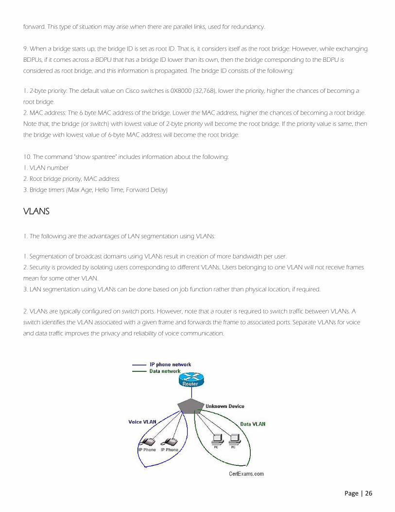
2. VLANs are typically configured on switch ports. However, note that a router is required to switch traffic between VLANs. A
switch identifies the VLAN associated with a given frame and forwards the frame to associated ports. Separate VLANs for voice
and data traffic improves the privacy and reliability of voice communication.
Page | 27
A single physical port on a router can support one or more VLANs by use of sub-interfaces. There is no need to have as many
physical ports on a router as that of VLANs.
3. Inter-VLAN communication can occur only if the router is configured with appropriate sub-interfaces. In this case, there are 4
VLANs (VLANs 100,200,300, and 400), in addition to VLAN 1 (management VLAN). Therefore, 5 sub-interfaces have to be
configured on the router interface connecting the switch.
A roll-over cable is required for connecting a terminal to the Console port of a router/switch.
VTP
1. VLAN Transport Protocol (VTP) information can be distributed throughout the
network to all stations including servers, routers, and switches.
The VLAN transport protocol are:
ISL: ISL (Inter Switch Link) is the VLAN transport protocol used over Fast Ethernet trunked link.
802.1: 802.1 is the VLAN transport protocol used over FDDI trunked link.
LANE: LAN Emulation (LANE) is the VLAN transport protocol used across an ATM trunked link.
The default VTP configuration parameters for the Catalyst switch are as follows:
1. VTP domain name: None
2. VTP mode: Server
3. VTP password: None
4. VTP pruning: Disabled
5. VTP trap: Disabled
2. The VTP domain name can be specified manually or learned across a configured trunk line from a server with a domain name
configured. By default, the domain name is not set.
If you configure a VTP password, VTP does not function properly unless you assign the same password to each switch in the
domain.
VTP trap is disabled by default. If you enable this feature, it causes an SNMP message to be generated every time a new VTP
message is sent.
3. VTP is a Layer 2 messaging protocol. It carries configuration information throughout a single domain. VTP operates in one of
three modes:
1. Server mode: VTP Servers can create, modify, or delete VLANs and other configuration parameters for the specified VLAN
domain.
2. Client mode: A VTP client can't create, change, or delete VLANs.
3. Transparent mode: A VTP transparent mode is used when a switch is not required to participate in VTP, but only pass the
information to other switches. Transparent switches don't work either as Server or clients.
Page | 28
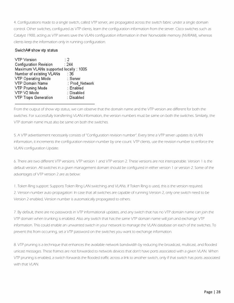
4. Configurations made to a single switch, called VTP server, are propagated across the switch fabric under a single domain
control. Other switches, configured as VTP clients, learn the configuration information from the server. Cisco switches such as
Catalyst 1900, acting as VTP servers save the VLAN configuration information in their Nonvolatile memory (NVRAM), whereas
clients keep the information only in running configuration.
From the output of show vtp status, we can observe that the domain name and the VTP version are different for both the
switches. For successfully transferring VLAN information, the version numbers must be same on both the switches. Similarly, the
VTP domain name must also be same on both the switches.
5. A VTP advertisement necessarily consists of "Configuration revision number". Every time a VTP server updates its VLAN
information, it increments the configuration revision number by one count. VTP clients, use the revision number to enforce the
VLAN configuration Update.
6. There are two different VTP versions. VTP version 1 and VTP version 2. These versions are not interoperable. Version 1 is the
default version. All switches in a given management domain should be configured in either version 1 or version 2. Some of the
advantages of VTP version 2 are as below:
1. Token Ring support: Supports Token Ring LAN switching and VLANs. If Token Ring is used, this is the version required.
2. Version number auto propagation: In case that all switches are capable of running Version 2, only one switch need to be
Version 2 enabled, Version number is automatically propagated to others.
7. By default, there are no passwords in VTP informational updates, and any switch that has no VTP domain name can join the
VTP domain when trunking is enabled. Also any switch that has the same VTP domain name will join and exchange VTP
information. This could enable an unwanted switch in your network to manage the VLAN database on each of the switches. To
prevent this from occurring, set a VTP password on the switches you want to exchange information.
8. VTP pruning is a technique that enhances the available network bandwidth by reducing the broadcast, multicast, and flooded
unicast messages. These frames are not forwarded to network devices that don't have ports associated with a given VLAN. When
VTP pruning is enabled, a switch forwards the flooded traffic across a link to another switch, only if that switch has ports associated
with that VLAN.
Page | 29
Security
1. The following are the important characteristics of SDM (Security Device Manager):
1. SDM doesn’t use Telnet/SSH for communicating with the router. Actually, a web server will be running on the router, and the
client software will be running on the host computer.
2. SDM uses web interface on a PC, and the user needs to connect to the router over an IP network and not through Console.
3. The configuration will be written to the router’s running configuration file only after the Finish button is pressed on the SDM
wizard. Note that the configuration is not written to the start-up configuration.
4. SDM configuration wizard allows DHCP client services to be configured, with an option to add PAT services or not.
2. The Internet architecture provides an unregulated network path to attack innocent hosts. Denial-of-service (DoS) attacks exploit
this to target mission-critical services.
DoS attacks, are explicit attempts to block legitimate users system access by reducing system availability. Any physical or host-based
intrusions are generally addressed through hardened security policies and authentication mechanisms. Although software
patching defends against some attacks, it fails to safeguard against DoS flooding attacks, which exploit the unregulated forwarding
of Internet packets.
3. An intrusion prevention system is a computer security device that monitors network and/or system activities for malicious or
unwanted behavior and can react, in real-time, to block or prevent those activities.
Intrusion Detection Systems (IDS) detect unauthorized access attempts. There are basically two main types of IDS being used today:
Network based (a packet monitor), and Host based (looking for instance at system logs for evidence of malicious or suspicious
application activity in real time).
Both IPS and IDS are closely related, and IPS is considered as an extension of IDS.
Page | 30
Miscellaneous
Network Devices
1. Repeaters, Bridges, and Routers:
The most frequently used network devices may be categorized as repeaters, hubs, switches, and routers. These devices let you
connect computers, printers, and other devices to communicate with each other. The medium that is used for communication is
usually cable (optical or copper) and air (Wi-Fi, Bluetooth, etc.).
A repeater is a basic device that simply amplifies the input signals and retransmits. It is used to extend the range of a network
segment.
For example, the range of a 10BaseT network segment is 100meters by default. If the end devices are at a distance more than 100
meters, you will require a repeater so that the transmitted signals are received at the destination device without losing any
information.
A bridge/switch essentially forwards the frames that come from one port to other ports. A switch is used to connect two or more
network segments. A switch learns the physical addresses of sending devices by reading the MAC address and mapping it to the
port number through which the frame had arrived.
This way, it will quickly learn which MAC address belongs to which switch port, and stores the information in a table (called MAC
table). Then onwards, it will send a frame only to the port that connects to the destination device (as specified in the frame). MAC
addresses are layer-2 addresses. Because a switch works on MAC addresses, we can classify switches as Layer-2 devices.
A router is used to route packets by connecting two or more networks together. They work at layer-3 of the OSI model. They route
packets based on the IP addresses where as a switch forwards packets based on the MAC addresses. A router needs to
disseminate an incoming packet down to its IP address and route it to destination based on information available in its routing
table.
I. Repeaters work at Physical layer (Layer 1),
II. Bridges and simple switches work at Data Link Layer (Layer 2),
III. Routers work at Network Layer (Layer 3) of ISO Reference Model.
2. CSU / DSU is an acronym for Channel Service Unit / Data Service Unit. CSU/DSU is part of Customer Premise Equipment
(CPE). CSU / DSU connect to a Central Office (CO), a telephone switching company located nearer to the customer.
3. For using full duplex Ethernet transmission, a switch is required. A Hub cannot support full duplex transmission. In full
duplex mode, there will not be any frame collisions.
WAN Devices
Page | 31
1. WAN (Wide Area Network) devices extend the reach of LAN (Local Area Network) devices. WANs typically span over a
wide area, such over multiple cities / countries. WANs are connected over serial lines that operate at lower speeds than LANs .
Some of the WAN devices are:
1. Routers: Routers are responsible for routing the packets in an internetwork.
2. Modems: Modems connect to public telephone circuits through dial-up.
3. CSU/DSU: Stands for Channel Service Unit / Data Service Unit. CSU/DSUs are used for connecting to Central Office of a
Telephone switching company and provide serial WAN connections.
4. Communication Servers: These are used for dial in/out to remote users. Provides RAS Remote Access Server) functionality.
5. Multiplexers (mux): Multiplexers combine two or more signals before transmitting on a single channel. Multiplexing can be done
by sharing "time" or "frequency".
Wireless LAN
1. WEP uses RC4 stream encryption
WPA uses (as describe above) TKIP/MIC Encryption.
WPA2 uses AES-CCMP Encryption
2. In "ad-hoc" or Independent Basic Service Set (IBSS) configuration there is no backbone infrastructure. Mobiles can talk to each
other without the use of an Access Point (AP). In the Extended Service Set (ESS) configuration, there will be two or more Access
Points (APs), and users can freely roam between the Access Points without any disconnection or reconfiguration.
Others
1. HTTP is the protocol used for accessing the World Wide Web services. HTTP operates over TCP/IP. TCP/IP is the protocol, which
is used by all internet applications such as WWW, FTP, Telnet etc. IPX/SPX is proprietary protocol stack of Novell NetWare.
2. Route summarization is calculated as below:
Step 1:
1. Take the first IP: 172.24.54.0/24 : 172.24. 0 0 1 1 0 1 1 0.0
2. Take the second IP: 172.24.53.0/24 : 172.24. 0 0 1 1 0 1 0 1.0
Note that we are not really concerned about the octets that have equal decimal values. This is because they don’t come into p lay
while calculating summarization route, in this case.
Step 2:
Count the number of bits in the third octet that are aligned (or lined up) with same values. In this case 6 bits are lined up in the
third octet. The summarization route is calculated by adding this number (6) to the octets preceding the third (first and second
octets).
Therefore, the number of bits in the summarized route is 8+8+6 = 22
Step 3:
Calculate the decimal equivalent for third octet with 6 bits as given in the matching binary. That is 0 0 1 1 0 1 x x. Note x is because
it corresponds to non-matching binary number. It is equal to 128*0 + 64*0 + 32*1 + 16*1 + 8*0 + 4*1 or 32+16+4 or 52.
Page | 32
Therefore, the summarized route is:
172.24.52.0/22
3. Debugging output takes priority over other network traffic. Also, the debug all command generates more output than any
other debug command, and it can severely affect the router's performance. In practically all cases, it is best to use more specific
debug commands.
4. Ethernet II has a type field to identify the upper-layer protocol. 802.3 has only a length field and can't identify the upper-layer
protocol.
5. Hold down timers prevents regular update messages from reinstating a route that has gone bad. Here, if a route fails, the router
waits a certain amount of time before accepting any other routing information about that route. Hold downs tell routers to hold
any changes that might affect routes for some period of time. The holddown period is usually calculated to be just greater than
the period of time necessary to update the entire network with a routing change.
6. Congestion avoidance, Windowing, and Buffering are three types of flow control.
7. Convergence is the term used to describe the state at which all the internetworking devices, running specific routing protocol,
are having the same information about the internetwork in their routing tables. The time it takes to arrive at common view of the
internetwork is called Convergence Time.
8. IP helper addresses forward a client broadcast address (such as a DHCP or BOOTP requests) to a unicast or directed broadcast
address. Helper-address is required due to the fact that routers do not forward broadcasts. By defining a helper-address, a router
will be able to forward a broadcast from a client to the desired server or network. There can be more than one helper-address on
a network. The helper-address must to be defined on the interface that receives the original client broadcast.
Note that "ip unnumbered" command is used to enable IP processing on a serial interface without assigning a specific IP address to
the interface.
9. Runts are packets that are smaller than the medium's minimum packet size. For example, Ethernet has a minimum allowed
packet size of 64 bytes. Any packet that is less than 64 bytes in size is considered a runt in Ethernet.
Giants are packets that bigger than the medium's maximum packet size. Fro example, Ethernet has a maximum allowed packet
size of 1,518 bytes. Any packet that is bigger than 1,518 bytes is considered a Giant in Ethernet.
CRC error occurs when the check sum calculated at the receiving end of the frame does not match with the check sum calculated
at the source end.
The most probable reasons for runts, giants, and CRC errors is frame collisions while traveling from source to destination. It is also
possible that a network card or device is bad and generating runts and giants.
10. Standard adopted for Ethernet CSMA/CD by IEEE Committee is 802.3. 100BaseT (Fast Ethernet) uses IEEE803.2u standard
which incorporates CSMA/CD protocol.
Page | 33
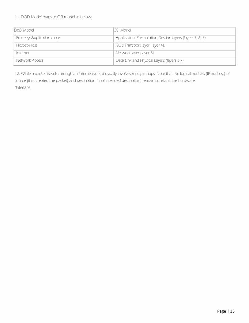
11. DOD Model maps to OSI model as below:
DoD Model OSI Model
Process/ Application maps Application, Presentation, Session layers (layers 7, 6, 5).
Host-to-Host ISO's Transport layer (layer 4).
Internet Network layer (layer 3)
Network Access Data Link and Physical Layers (layers 6,7)
12. While a packet travels through an Internetwork, it usually involves multiple hops. Note that the logical address (IP address) of
source (that created the packet) and destination (final intended destination) remain constant, the hardware
(Interface)