Embed Size (px)
Citation preview

ACC_WE_DF 4000 KITCHEN DESIGN & FITTING OUT (V 2-2 - Dec 08) Page 1 of 54
... DF_4000...
HOTEL KITCHENS and associated areas
Mid-scale & Up-scale hotels
Design and fitting out
NEW BUILDINGS OR REFURBISHMENTS
TECHNICAL AND FUNCTIONAL CRITERIA
International Edition V2-2 Dec 2008
This document is intended for the use of designers and constructors
for the preparation of project specifications
ACCOR has published this document for use on its projects; its distribution or reproduction for other purposes is not permitted

ACC_WE_DF 4000 KITCHEN DESIGN & FITTING OUT (V 2-2 - Dec 08) Page 2 of 54
CONTENTS
1 INTRODUCTION 5 2 SANITARY SAFETY OF FOODSTUFFS 6
2.1 THE "FOOD WAY FORWARD" PRINCIPLE .......................................................................................................6 2.2 HACCP PROCEDURES .....................................................................................................................................8
3 STAFF COMFORT, HEALTH AND SAFETY 9 3.1 STAFF COMFORT..............................................................................................................................................9
3.1.1 WORKING CONDITIONS...........................................................................................................................9 3.1.2 AMBIENT TEMPERATURE ........................................................................................................................9 3.1.3 NOISE LEVEL .........................................................................................................................................9 3.1.4 CLEAR CEILING HEIGHT ..........................................................................................................................9 3.1.5 VIEW TO THE OUTSIDE AND NATURAL LIGHT .............................................................................................9 3.1.6 ARTIFICIAL LIGHTING..............................................................................................................................9
3.2 STAFF HYGIENE ...............................................................................................................................................9 3.3 STAFF SAFETY................................................................................................................................................10
3.3.1 ELECTRICAL SAFETY ............................................................................................................................10 4 FIRE SAFETY AND SUSTAINABLE DEVELOPMENT CRITERIA 10
4.1 FIRE SAFETY...................................................................................................................................................10 4.1.1 STAFF EMERGENCY EXITS ....................................................................................................................10 4.1.2 ISOLATION OF ROOMS ..........................................................................................................................10 4.1.3 COLD ROOM PANELS............................................................................................................................11 4.1.4 ISOLATION OF THE HOOD EXTRACT DUCT ...............................................................................................11 4.1.5 CASE OF KITCHEN OPEN ONTO THE RESTAURANT ...................................................................................11 4.1.6 AUTOMATIC FIRE EXTINCTION OVER THE COOKING RANGE.......................................................................11 4.1.7 FIRE DETECTION IN THE KITCHEN ZONE .................................................................................................11 4.1.8 FLOOR, WALL AND CEILING FINISHES .....................................................................................................11
4.2 KITCHEN GAS SAFETY...................................................................................................................................12 4.2.1 GAS SUPPLY .......................................................................................................................................12 4.2.2 GAS DETECTION ..................................................................................................................................12 4.2.3 AUTOMATIC SAFETY DEVICES ...............................................................................................................12
4.3 SECURITY (INTRUSION) .................................................................................................................................12 4.3.1 ACCESS CONTROL ...............................................................................................................................12 4.3.2 LOCKING OF THE AREAS .......................................................................................................................12
4.4 SUSTAINABLE DEVELOPMENT......................................................................................................................13 5 GUIDELINES FOR THE DESIGN OF A KITCHEN PROJECT 14
5.1 THE FOOD AND BEVERAGE PROJECT BRIEF..............................................................................................14 5.2 THE DESIGN OF THE FOOD AND BEVERAGE INSTALLATIONS..................................................................15
5.2.1 KITCHEN CONSULTANT.........................................................................................................................15 5.2.2 CHOICE OF ENERGY SOURCES..............................................................................................................15 5.2.3 LIMITS TO THE EXTENT OF WORK...........................................................................................................15 5.2.4 CONNECTION OF SERVICES ..................................................................................................................15
5.3 FUNCTIONALITY .............................................................................................................................................16 5.4 FUNCTION SERVICE, SERVED AT TABLE, TO THE PLATE ..........................................................................16 5.5 THE GENERAL LAYOUT OF THE ROOMS......................................................................................................17 5.6 FOOD AND BEVERAGE AREAS......................................................................................................................18 5.7 CIRCULATION FLOWS FOR STAFF AND FOODSTUFFS...............................................................................19
5.7.1 HORIZONTAL CIRCULATION ...................................................................................................................19 5.7.2 GOODS LIFT ........................................................................................................................................19 5.7.3 VEHICLE ACCESS AND SERVICE COURTYARD..........................................................................................19
5.8 SETTING OUT AND FITTING OUT OF ASSOCIATED AREAS ........................................................................20 5.8.1 RUBBISH ROOMS AND AREAS ................................................................................................................20 5.8.2 KITCHEN ZONE ELECTRICAL DISTRIBUTION BOARD ..................................................................................20 5.8.3 COLD ROOM COMPRESSORS ................................................................................................................20 5.8.4 GREASE TRAP .....................................................................................................................................20 5.8.5 STAFF CLOAKROOMS AND TOILETS........................................................................................................20
5.9 CONTROL OVER NUISANCES FROM THE KITCHEN ....................................................................................21 5.9.1 ACOUSTIC CRITERIA ............................................................................................................................21 5.9.2 RISK OF SMELLS ..................................................................................................................................21 5.9.3 RISKS OF WATER DAMAGE....................................................................................................................21 5.9.4 PROTECTION OF THE DRINKING WATER SERVICES ..................................................................................21 5.9.5 PROTECTION OF THE WASTE WATER SERVICES ......................................................................................21
6 ANALYSIS OF THE DESIGN DATA 22 7 STRUCTURAL REQUIREMENTS 23
7.1 STRUCTURE....................................................................................................................................................23 7.1.1 FLEXIBILITY OF THE KITCHEN ZONE .......................................................................................................23 7.1.2 BASES OF CALCULATION ......................................................................................................................23 7.1.3 THERMAL INSULATION OF THE BUILDING ................................................................................................23

ACC_WE_DF 4000 KITCHEN DESIGN & FITTING OUT (V 2-2 - Dec 08) Page 3 of 54
7.1.4 FLOOR OF THE KITCHEN ZONE ..............................................................................................................23 7.2 EXTERNAL JOINERY.......................................................................................................................................24
7.2.1 WINDOWS IN THE KITCHEN AREAS .........................................................................................................24 7.2.2 VENTILATION GRILLES IN EXTERNAL WALLS ............................................................................................24 7.2.3 EXTERNAL DOORS ...............................................................................................................................24
8 INTERNAL FITTING-OUT 25 8.1 PARTITIONS AND DOORS ..............................................................................................................................25
8.1.1 PARTITIONS ........................................................................................................................................25 8.1.2 INTERNAL DOORS ................................................................................................................................25
8.2 CONSTRUCTION OF COLD ROOMS ..............................................................................................................26 8.2.1 LAYOUT OF THE COLD ROOMS ..............................................................................................................26 8.2.2 COLD ROOM PANELS............................................................................................................................26 8.2.3 COLD ROOM DOORS ............................................................................................................................26 8.2.4 FLOORS OF COLD ROOMS.....................................................................................................................26 8.2.5 CLEANING...........................................................................................................................................26 8.2.6 CONTROL AND ALARM ELEMENTS ..........................................................................................................26
8.3 FLOORS, WALLS AND CEILINGS ...................................................................................................................27 8.3.1 SCHEDULE OF FINISHES .......................................................................................................................27 8.3.2 ARRANGEMENTS TO FACILITATE CLEANING ............................................................................................27 8.3.3 TILED FLOORING..................................................................................................................................28 8.3.4 SKIRTINGS ..........................................................................................................................................28 8.3.5 TILED BASES .......................................................................................................................................28 8.3.6 FLOOR GULLIES AND CHANNELS............................................................................................................29 8.3.7 WALLS IN THE KITCHEN ZONE ...............................................................................................................29 8.3.8 TRIM AT WALLS ANGLES .......................................................................................................................29 8.3.9 PROTECTION OF THE WALLS .................................................................................................................29 8.3.10 CEILINGS ............................................................................................................................................30 8.3.11 LIGHT FITTINGS ...................................................................................................................................30 8.3.12 CLEANING POINTS ...............................................................................................................................30
9 SERVICES INSTALLATIONS 31 9.1 PLUMBING.......................................................................................................................................................31
9.1.1 DESIGN CRITERIA ................................................................................................................................31 9.1.2 PROTECTION OF DRINKING WATER ........................................................................................................31 9.1.3 PROTECTION AGAINST NOISE................................................................................................................31 9.1.4 COLD WATER AND HOT WATER DISTRIBUTION.........................................................................................32 9.1.5 KITCHEN WASTE WATER DRAINAGE .......................................................................................................33 9.1.6 GREASE TRAP .....................................................................................................................................35
9.2 GAS DISTRIBUTION IN THE KITCHEN ...........................................................................................................36 9.3 VENTILATION AND AIR CONDITIONING OF THE KITCHEN ZONE ...............................................................37
9.3.1 VENTILATION OF THE ROOMS ................................................................................................................37 9.3.2 EXTRACT HOODS .................................................................................................................................38 9.3.3 AUTOMATIC FIRE SUPPRESSION SYSTEM OVER THE COOKING RANGE .......................................................39 9.3.4 HOOD (TYPE H) WITH ULTRA VIOLET TECHNOLOGY .................................................................................39 9.3.5 FILTER CEILINGS .................................................................................................................................40 9.3.6 REGULATION OF THE EXTRACTION FLOW RATE .......................................................................................40 9.3.7 VENTILATION DUCTWORK SYSTEM.........................................................................................................40 9.3.8 EXTRACT AND AIR DISCHARGE FANS......................................................................................................41 9.3.9 MAKE-UP AIR SUPPLY ..........................................................................................................................41 9.3.10 COOLED AREAS ...................................................................................................................................42 9.3.11 SMOKE EXTRACTION FUNCTION VIA THE KITCHEN HOOD .........................................................................42 9.3.12 NATURAL SMOKE EXTRACTION FROM THE KITCHEN .................................................................................42 9.3.13 OPEN FIREPLACE.................................................................................................................................43
9.4 KITCHEN ELECTRICITY ..................................................................................................................................43 9.4.1 GENERAL REQUIREMENTS ....................................................................................................................43 9.4.2 KITCHEN ELECTRICAL DISTRIBUTION......................................................................................................44 9.4.3 "POWER" ELECTRICAL DISTRIBUTION BOARDS AND PANELS .....................................................................44 9.4.4 SUPPLIES TO THE KITCHEN EQUIPMENT .................................................................................................44 9.4.5 LIGTH FITTINGS IN THE KITCHEN ZONES..................................................................................................45 9.4.6 EMERGENCY LIGHTING.........................................................................................................................45
9.5 TELEPHONE, COMPUTERS............................................................................................................................46 9.6 FIRE PROTECTION .........................................................................................................................................46 9.7 COLD ROOMS .................................................................................................................................................46 9.8 GOODS LIFT ....................................................................................................................................................46
APPENDICES – DOCUMENTATION 47 APPENDIX A DEVICES FOR PROTECTION OF DRINKING WATER SERVICES 47 APPENDIX B GREASE TRAPS 48 APPENDIX C EXTRACTION FLOW RATES FROM KITCHEN HOODS 50 APPENDIX D PRINCIPLES FOR KITCHEN HOODS 51 APPENDIX E REGULATION OF THE HOODS 54
ACC_WE_DF 4000 KITCHEN DESIGN & FITTING OUT (V 2-2 - Dec 08) Page 4 of 54
ALPHABETICAL INDEX
A ABBREVIATIONS ................................................................. 5 ACCESS CONTROL............................................................ 12 ACOUSTIC CRITERIA......................................................... 21 AIR TRANSFER................................................................... 37 ANALYSIS OF THE DESIGN DATA..................................... 22 ASSOCIATED AREAS......................................................... 20 AUTOMATIC FIRE EXTINCTION......................................... 11 AUTOMATIC FIRE SUPPRESSION .................................... 41 C CEILINGS ............................................................................ 27 CHANNEL AND GRATING .................................................. 34 CHOICE OF ENERGY SOURCES....................................... 15 CIRCULATION FLOWS FOR FOODSTUFFS ...................... 19 CIRCULATION FLOWS FOR STAFF................................... 19 COLD ROOM COMPRESSORS .......................................... 20 COLD ROOM PANELS........................................................ 11 COLD ROOMS .................................................................... 48 COMPUTERS...................................................................... 47 CONSTRUCTION OF COLD ROOMS ................................. 26 CONSTRUCTION REGULATIONS ........................................ 5 COOLED AREAS................................................................. 44 D DESIGN OF THE FOOD AND BEVERAGE I INSTALLATIONS ................................................................ 15 DIAGRAM OF A HOOD ....................................................... 39 DISHWASHER HOOD ......................................................... 41 DRAINAGE CHANNELS...................................................... 28 E ELECTRICAL DISTRIBUTION BOARD .............................. 20 EMERGENCY LIGHTIN....................................................... 46 EMERGENCY SWITCHES .................................................. 46 EXTERNAL DOORS ............................................................ 24 EXTRACT AND AIR DISCHARGE FANS............................. 43 EXTRACT HOODS .............................................................. 39 F FIRE PROTECTION ............................................................ 47 FIRE SAFETY...................................................................... 10 FLEXIBILITY OF THE KITCHEN ZONE ............................... 23 FLOOR GULLIES AND CHANNELS .................................... 29 FLOOR OF THE KITCHEN ZONE ....................................... 23 FLOOR, WALL AND CEILING FINISHES ............................ 11 FLOORS.............................................................................. 27 FOOD AND BEVERAGE AREAS......................................... 18 FOOD AND BEVERAGE PROJECT BRIEF......................... 14 FOOD WAY FORWARD ........................................................ 6 FUNCTION SERVICE.......................................................... 16 FUNCTIONAL LAYOUT......................................................... 6 FUNCTIONALITY................................................................. 16 G GAS DISTRIBUTION IN THE KITCHEN .............................. 36 GENERAL LAYOUT OF THE ROOMS................................. 17 GOODS LIFT ....................................................................... 19 GREASE TRAP ............................................................. 20, 35 H HACCP PROCEDURES ........................................................ 8 I INTERNAL DOORS ............................................................. 25
ISOLATION OF ROOMS ......................................................10 ISOLATION OF THE HOOD EXTRACT DUCT.....................11 K KITCHEN CONSULTANT ....................................................15 KITCHEN ELECTRICITY......................................................45 KITCHEN GAS SAFETY ......................................................12 KITCHEN OPEN ONTO THE RESTAURANT.......................11 L LIGHT FITTINGS .................................................................30 LIGTH FITTINGS IN THE KITCHEN ZONES........................46 LIMITS TO THE EXTENT OF WORK ...................................15 LOCKING OF THE AREAS ..................................................12 M MAKE-UP AIR SUPPLY ......................................................43 N NATURAL SMOKE EXTRACTION FROM THE KITCHEN ..44 NUISANCES FROM THE KITCHEN.....................................21 P PARTITIONS ........................................................................25 PRINCIPLE OF WATER DISTRIBUTION .............................32 PRINCIPLES FOR KITCHEN HOODS .................................53 PROTECTION OF THE DRINKING WATER SERVICES......21 PROTECTION OF THE WALLS ...........................................29 PROTECTION OF THE WASTE WATER SERVICES ..........21 R REGULATION OF THE HOODS ..........................................56 RISK OF SMELLS ................................................................21 RISKS OF WATER DAMAGE...............................................21 RUBBISH ROOMS AND AREAS..........................................20 S SANITARY SAFETY OF FOODSTUFFS ................................6 SECURITY (INTRUSION......................................................12 SERVICE COURTYARD ......................................................19 SKIRTINGS..........................................................................28 SLOT CHANNELS................................................................34 STAFF CLOAKROOMS AND TOILETS................................20 STAFF COMFORT.................................................................9 STAFF EMERGENCY EXITS ...............................................10 STAFF HYGIENE...................................................................9 STAFF SAFETY ...................................................................10 STRUCTURAL REQUIREMENTS ........................................23 STRUCTURE .......................................................................23 SUSTAINABLE DEVELOPMENT .........................................13 T TELEPHONE .......................................................................47 TERMINOLOGY.....................................................................5 THERMAL INSULATION OF THE BUILDING.......................23 TILED BASES ......................................................................28 V VEHICLE ACCESS ..............................................................19 VENTILATION DUCTWORK SYSTEM.................................42 VENTILATION GRILLES IN EXTERNAL WALLS .................24 VENTILATION OF THE ROOMS..........................................37 W WALLS ................................................................................27 WATER METERS.................................................................32 WINDOWS IN THE KITCHEN AREAS .................................24

ACC_WE_DF 4000 KITCHEN DESIGN & FITTING OUT (V 2-2 Dec 08) Page 5 sur 54
1 INTRODUCTION
OBJECT OF THE DOCUMENT The technical and functional criteria cover the whole chain through the food and beverage areas and their corridors, from the point of delivery up to the removal of rubbish. Field of application:
NEW BUILDINGS
&
REFURBISHMENT OF EXISTING BUILDINGS
TERMINOLOGY KITCHEN
• Indicates globally all the food and beverage service areas, such as: kitchen, relay-kitchens, grill, rotisserie, wash-up, pantries, coffee room, room service kitchen or pantry, bar pantry, stores, cold rooms, rubbish rooms, delivery areas, food service corridors, goods lifts, as applicable to each project.
BANQUETING SERVICE
• Indicates, without distinction, all services for groups, where the same food is served to those attending, whatever the type of the event (conferences, meetings, parties, etc.)
CONSTRUCTORS
• Indicates, without distinction, all those people who are responsible for the design of the project, the supervision of the site, the execution of the works and the technical supervision of the building work, the services installations and the external works (architect, interior designer, specifier, quantity surveyor, consulting engineer, fire safety officer, technical supervisor, contractors, suppliers, etc.)
CONSTRUCTION REGULATIONS
• "Construction regulations" shall be deemed to mean all the regulations or requirements of the authorities applicable to the project affecting all aspects of the works: food and beverage hygiene, fire safety, staff comfort and safety, protection of the environment, etc.
WARNING The ACCOR technical and functional criteria define the minimum principles which should be applied to all construction or refurbishment projects, in all countries. They shall be used as guides for the technical desi gn of each project. The designers appointed to carry out this design (architect and consulting engineers for the construction, the mechanical services installations and kitchen equipment) shall make an analysis of all the functional, technical and statutory data and shall coordinate their designs so as to define an overall, coherent project. The design must incorporate the application of the codes, standards and regulations applicable locally. The m ost stringent between the local codes and the Accor requirements shall be implemented.
ABBREVIATIONS (APPLICABLE GENERALLY TO THE FRENCH
VERSION OF THIS DOCUMENT ONLY)
RE Smoke rating REI Fire rating BAES Autonomous emergency lighting unit BET Consulting Engineers CCH Construction and residential code
(under French regulations) CDT Labour code (under French regulations) ERP Public building (under French regulations) HACCP Hazard Analysis Critical Control Point IGH High rise building (under French regulations) CMSI Fire safety central control system SSI Fire detection protection system Refrigerants CFC Chlorofluorocarbons HCFC Chlorinated and fluorinated hydrocarbons HFC Fluorinated hydrocarbons

ACC_WE_DF 4000 KITCHEN DESIGN & FITTING OUT (V 2-2 Dec 08) Page 6 of 54
2 SANITARY SAFETY OF FOODSTUFFS
2.1 THE "FOOD WAY FORWARD" PRINCIPLE This title summarises three essential principles: 1 Products always move forwards through the kitchen. They never go back to where they have been
previously. 2 They are worked on or stored with products of an
equivalent level of cleanliness. 3 Each transformation gives them a higher status of
cleanliness.
It is therefore possible to distinguish between three main states:
"Unprocessed" "Clean" "Finished"
Stored with "unprocessed"
products.
Worked on or stored with
"clean" products.
Worked on or stored with "finished" products.
No mixing of "unprocessed" / "clean" / "finished".
A "clean" edible foodstuff shall never meet an item of rub bish
• Peelings, rubbish and "clean" products shall never meet or take the same route: • The vegetable preparation room shall have two doors: one "dirty" entrance / exit and one "clean" exit. • The dustbins from the wash-up shall not use the same corridor as the products leaving a cold room. • The same goods lift should not be used for bringing down the dustbins from the functions pantry, for delivering clean linen to the
bedrooms, for delivering breakfast trays, or for bringing down dirty linen, except if refuse bags are sealed and carried within a closed container.
FUNCTIONAL LAYOUT
SEMINARS FUNCTIONS
DIRTY
CLEAN UNTREATED
FINISHED
RESTAURANT
Rubbish Seletive sorting
Pantry
Dishwash
Checking Unpacking
Storage Cleaning
Cold room
Cooking range
Cold preparation
D
istr
ibut
ion
Wash-up crockery

AC
C_W
E_D
F 4000 K
ITC
HE
N D
ES
IGN
& F
ITT
ING
OU
T (V
2-2 Dec 08)
Page 7 of 54
•
Goods deliveries
Cleaning/ Unpacking Rubbish removal
Rubbish removal
Pot wash
Crockery wash
Boxes Organic rubbish
Checking and Reception of Goods
Restaurant Disposal
FOOD WAY FORWARD ORGANISATIONAL FOOD WAY FORWARD ORGANISATIONAL FOOD WAY FORWARD ORGANISATIONAL FOOD WAY FORWARD ORGANISATIONAL
DIAGRAMDIAGRAMDIAGRAMDIAGRAM
Food & Foodstuffs
Circuit
Glass
Rubbish Circuit
Vegetable Preparation Meat Preparation Fish Preparation
"Untreated products" storage
Cold rooms Freezers Store
Function room
Function pantry / Relay kitchen
Clean crockery storage
To Bedroom lift
Rubbish removal
Main kitchen enclosure
Prepared Products Cold Room
Patisserie
Cold room
Coffee Pantry
Cold preparation Function Preparation Cooking range
Room service pantry
This organisational diagram is that for full service with restaurant, functions and
room service.
The same principles shall remain applicable to simple
catering or breakfast service, but omitting the
unused functions.

ACC_WE_DF 4000 KITCHEN DESIGN & FITTING OUT (V 2-2 Dec 08) Page 8 of 54
2.2 HACCP PROCEDURES HACCP procedures comprise a systematic approach to the identification, location, evaluation and control of potential risks relating to the wholesomeness of foodstuffs in the food chain. They consist of identifying specific risks, determining points of control of those risks and defining the preventive measures to implement in order to control those risks. They take the form of written procedures defined by the chef, who then ensures that they are properly applied. Designs for kitchens must be produced with these procedures in mind, particularly:
• a minimum of critical points; (examples: proper definition of the routes to be taken by staff, foodstuffs and rubbish, cooling of the cold preparation area) • ease of maintenance of the rooms and items of
equipment; (examples: washable floors and walls, no exposed pipework, stainless steel equipment, wash-down points) • means of control.
(example: display and recording of temperatures in cold rooms).
REFURBISHMENT OF EXISTING BUILDINGS HACCP procedures must be taken into account in all refurbishment projects as, if the constraints of the existing premises and of the budget do not allow ideal conditions to be provided, there is a close relationship between:
• existing critical points; • improvements that can be made; • critical points that will remain; • the new procedures that arise from them.
This means that a two-stage procedure is needed: 1 – Determination of the critical points
• Marking on the drawing a division into zones (reception, cold production, etc.).
• Establishing for each zone an accurate schedule of condition of the premises and of the plant.
• Tracing the circuits (foodstuffs, staff, rubbish) and identifying critical points.
2 – By visualising the critical points, undertaking reflection about the steps to be taken to avoid contamination
• either by means of works or items of equipment in an order of priority to be defined,
• or by implementing new procedures. These procedures should be combined with the design of the new catering concept, if proposed as part of the refurbishment brief.
Risk control
Identification Control Points
Preventive measures
Staff circuits for foodstuffs,
for rubbish
Ease of maintenance : - of the areas
- of the equipment
Means of control
Two-stage procedure in refurbishment
projects
111 Determine the critical
points on the drawings of the existing building
222 Reflection on the steps to be taken

ACC_WE_DF 4000 KITCHEN DESIGN & FITTING OUT (V 2-2 Dec 08) Page 9 of 54
3 STAFF COMFORT, HEALTH AND SAFETY
3.1 STAFF COMFORT 3.1.1 WORKING CONDITIONS Proper ergonomic conditions are essential for work in a kitchen, which is tiring (working standing up) and requires close attention, as any negligence will lead to an immediate sanction: dissatisfaction of a consumer and, at the worst, food poisoning. 3.1.2 AMBIENT TEMPERATURE The ambient temperature in the working areas shall not be:
• Greater than 27°C • Less than 18°C (Exceptions – See art.
9.3.9) Depending on the climate, these conditions must be ensured by mechanical ventilation, with the addition of fresh air, and by a cooling system or static heating system if necessary. 3.1.3 NOISE LEVEL The noise level generated by the mechanical ventilation fan at high speed shall not be greater than 40 dB(A). The intermittent noise level generated by the running of the kitchen and wash-up equipment shall not be greater than 80 dB(A). 3.1.4 CLEAR CEILING HEIGHT The recommended clear ceiling height in the kitchen zone shall be 3 metres, or at least 2.80 m. A height of 2.50 m may be acceptable in the stores and corridor zones.
3.1.5 VIEW TO THE OUTSIDE AND NATURAL LIGHT The permanent work stations in the kitchen shall, as far as possible, have the benefit of natural light:
• by openings in the roof; • or by openings in the external wall.
Areas where staff work temporarily (stores pantries, wash-up) will generally not have windows. 3.1.6 ARTIFICIAL LIGHTING The lighting shall not deform the colours: fluorescent light source, temperature 3000°K, providing a lighting le vel of:
• 500 lux on work surfaces; • 200 lux in cloakrooms and toilets (at floor level); • 150 lux in corridors and staircases (at floor level); • 300 lux in cold rooms and stores (at floor level).
3.2 STAFF HYGIENE Kitchen staff shall have access to an electronic or elbow-controlled hand-rinse basin.
Catering staff shall have separate "men's" and "women's" toilets and cloakrooms: The lockers shall be:
• double for kitchen staff; • single for restaurant staff in uniform.
Double Width 50 cm
Single Width 30 cm

ACC_WE_DF 4000 KITCHEN DESIGN & FITTING OUT (V 2-2 Dec 08) Page 10 of 54
Rubbish
Restaurant
Kitchen Stores < 100 m²
3.3 STAFF SAFETY 3.3.1 ELECTRICAL SAFETY Emergency stop devices with key resetting shall be provided near sensitive workstations (cooking range, wash-up). All power cables to kitchen equipment shall connect into terminal boxes in order to protect live cables when equipment is disconnected.
Non-slip floor The kitchen floor shall be horizontal (*) and non-slip, with an R-Value slipperiness classification of R12 (DIN) or PC 27 (NF), shod foot > 27.
R12 (DIN) equivalent to PC 27 (NF) between 27° and 35° (High adhesion)
Slip angle (*) The normal construction tolerances defined under construction rules shall not be used to justify cross-falls that prevent washing water from flowing to floor gullies and channels.
4 FIRE SAFETY AND SUSTAINABLE DEVELOPMENT CRITERIA
4.1 FIRE SAFETY The minimum provisions of the Accor Group's BTH "FIRE SAFETY" method, shall be given in detail for each project by the Fire Safety officer, who shall take into account the specific requirements of the regulations applicable in the project location. 4.1.1 STAFF EMERGENCY EXITS The maximum distance A to be travelled to reach an exit (or a staircase), from the furthest point in a room, shall not exceed 40 metres. Dead end corridors B shall be no longer than 10 m. The kitchen zone shall have at least two exits C .
4.1.2 ISOLATION OF ROOMS Rubbish rooms are high-risk areas and shall be constructed with REI 120 floors and walls, with REI 60 doors fitted with door closers. The kitchen areas, pantries and stores are medium-risk areas and shall be separated from the service corridors and from the public areas with REI 60 floors and walls with REI 30 doors fitted with door closers (or RE 30 between the kitchen and the restaurant ). The load-bearing structures shall have a fire resistance "R" equal to the "REI" fire resistance of the constructions they bear. The stores shall have REI 60 partitions, but they may include internal wire mesh partitions, provided that their area does not exceed 100 m². REI 120 fire-resisting partition REI 60 fire-resisting partition Internal partitions Mesh partitions (These minimum isolation values may need increasing if the safety regulations of the particular location require it.)
A
B C
27°

ACC_WE_DF 4000 KITCHEN DESIGN & FITTING OUT (V 2-2 Dec 08) Page 11 of 54
≥ 50 cm
Kitchen Restaurant
4.1.3 COLD ROOM PANELS The composite panels – insulation and sheet metal facings – used for the floors, walls and ceilings of cold rooms shall be non-inflammable (category B of the European standard). These panels shall be used only for the cold rooms and not for partitioning the kitchen areas. Important – Electrical cables passing through shall be run in sleeves. No naked cable or live metal part shall ever be in contact with the thermal insulation. 4.1.4 ISOLATION OF THE HOOD EXTRACT DUCT The hood extract ducts shall be in steel and, outside the volume of the kitchen, shall be run in REI 60 (minimum), or 90 or 120, depending on the building, fire-resisting enclosures.
Every 3 meters in horizontal runs and at changes of direction, removable sealed hatches, backed up by REI hatches, shall enable the ductwork to be cleaned periodically. The cleaning hatch at the bottom of the vertical duct shall be fitted with a residue trap.
The "start – stop" control for the fan shall be visible, easily-accessible and fitted with a sign.
A Fan at top
B Steel duct
C REI 60 or 120 enclosure
D Hood and sensors
E Cooking range No fire damper on
extract duct from kitchen hoods
4.1.5 CASE OF KITCHEN OPEN ONTO THE RESTAURANT A specific study must be prepared by the Fire Safety Engineer. Accor recommends the following: A downstand at least 50 cm deep below the ceiling in the kitchen zone, in a non-combustible RE 15 material, shall be constructed immediately above the serveries so as to contain the smoke in the event of a fire. The extraction fan should be capable of running for one hour with smoke at 400°C and have a priority emergency e lectrical supply. The emergency power cut-off device for the kitchen equipment shall not switch off this fan. The "start – stop" control for the fan shall be visible, easily-accessible and fitted with a sign. 4.1.6 AUTOMATIC FIRE EXTINCTION OVER THE COOKING
RANGE Fryers shall have an automatic extinction system incorporated into the hood. In general, this equipment shall protect the whole area of the cooking range. 4.1.7 FIRE DETECTION IN THE KITCHEN ZONE Fire detection shall be provided in all rooms and corridors. In the cooking range zone, the fire detectors shall be of the optical / thermal type, in order to prevent accidental alarms. PARTICULAR CASE OF COLD ROOMS The kitchen fire detection shall also be installed in the void over the cold rooms. 4.1.8 FLOOR, WALL AND CEILING FINISHES The floor, wall and ceiling finishes, and also the suspended ceilings in the kitchen and its associated areas, shall be in low flammable materials (Class A of the European standard), or as per local authorities requirements if more stringent.
Access panel for maintenance
Maintenance access panels in duct + on fire protection
Maintenance access panels in duct + on fire protection + grease collector
(*) No fire damper required as the vertical duct is fully fire
protected. (A fire damper would even be detrimental if using the kitchen extract for smoke removal purposes)
≤ 3 m ≤ 3 m
D
E
B
A
C

ACC_WE_DF 4000 KITCHEN DESIGN & FITTING OUT (V 2-2 Dec 08) Page 12 of 54
4.2 KITCHEN GAS SAFETY 4.2.1 GAS SUPPLY Gas may be installed in kitchens when local regulations allows (in some countries, gas is not permitted in high rise buildings). In all cases:
• An emergency cut-off valve shall be installed externally for gas supply shut-off by emergency responders.
• A visible and easily-accessible stop valve shall also be provided within the kitchen, to isolate gas supply to the kitchen equipment.
(see gas distribution – art 9.2)
4.2.2 GAS DETECTION Accor recommends that automatic gas detection be installed in kitchens. Any gas leak to be indicated by an alarm at the hotel's central monitoring point and to trigger associated safety controls, as specified by Fire Safety Engineer or local codes. 4.2.3 AUTOMATIC SAFETY DEVICES Motorised gas switch-off valves shall generally be installed as per fire engineer’s specifications. They shall cut off gas supply in case of lack of ventilation or when fire alarm is activated (subject to Local Authority requirements).
4.3 SECURITY (INTRUSION) The Accor Group's "SECURITY" requirements shall be implemented, making allowance for the level of threat that exists on the site. 4.3.1 ACCESS CONTROL Staff and delivery entrances shall be provided with the necessary equipment to control the entry and exit of people:
• Card or code lock or electric locks + intruder alarm contact
• Intercom or videophone
• CCTV monitoring
4.3.2 LOCKING OF THE AREAS The stores, the chef's office and the staff cloakrooms shall be locked with key-, card- or code-operated locks. Particular case of cloakrooms The showers shall generally be included in the cloakrooms. On the other hand, access to the toilets shall be possible without a key. If facilities are provided for temporary/external staff, they shall include cloakrooms that are separate from those of the permanent staff, but the toilets may be common.

ACC_WE_DF 4000 KITCHEN DESIGN & FITTING OUT (V 2-2 Dec 08) Page 13 of 54
4.4 SUSTAINABLE DEVELOPMENT The Accor sustainable development guidelines shall be complied with when designing and fitting out kitchens & associated areas This includes :
• Staff comfort o See article 3.1
• Thermal insulation to the building o See article 7.1.3
• Selective sorting of rubbish o See article 5.8.1
• Acoustic comfort to hotel guests & Limiting
disturbance to neighbourhood See article 5.9 • Protecting potable water systems o See article 9.1.2
• Domestic hot water control o Legionella risk – See article 9.1.2 • Protecting sewage systems o Grease separators - See article 9.1.5
• Energy conservation o Extract hoods - See article 9.3.2 o Energy recovery on extract hoods - See article 9.3.13 o Lighting fittings - See article 9.4.5 o

ACC_WE_DF 4000 KITCHEN DESIGN & FITTING OUT (V 2-2 Dec 08) Page 14 of 54
5 GUIDELINES FOR THE DESIGN OF A KITCHEN PROJECT
5.1 THE FOOD AND BEVERAGE PROJECT BRIEF Any design of a kitchen and of food and beverage facilities for a hotel must be based on a "food and beverage project brief", which shall list, quantify and describe the various services and constraints to be taken into account: 1 - Context
• Type of hotel • Type(s) of customers • Country, etc.
2 - Definition of the facilities for preparation an d service The facilities shall be determined for each type of customer:
• Private hotel guests • Groups • Meetings • Other, etc.
a) The services and the times at which they are provided
Permanent
Breakfast Lunch Dinner
Bar Bar + café snacks
Hotel staff
Occasional
Conference breaks Conference meals
Function meals Training course meals
Room service Butler service
Outside catering
Caterer: meals prepared for outside
"Central" kitchen: for other establishments Airline catering: preparations on trays for airlines
b) Types of catering and method of service
Type Method of service
Gastronomic Brasserie
Grill or rotisserie Bistro or café
"Pub" "Salon de thé"
etc.
Table service
or mixed table and buffet Snack bar (counter)
Self-service Hors d’oeuvre, dessert buffet
Breakfast buffet Bedroom service
c) Estimate of the anticipated catering capacity
• Permanent service and occasional service (conferences, functions, etc.)
• Typical average • Peak periods • Annual total
d) Definition and layout of service zones
• Restaurant(s) • Function, conference, meeting rooms, etc. • Swimming pool restaurant and/or snack bar • Staff restaurant • etc.
3 - Frequency of supply
Types of products Supplies
"1ère Gamme" Unprocessed products
Daily and as available in the
markets "2ème Gamme" Canned products Weekly
"3ème Gamme" Frozen products Weekly
"4ème Gamme" Fresh, ready-to-use products
(also vacuum-packed)
Daily or twice weekly
"5ème Gamme" Prepared products (pre-cooked)
Daily or twice weekly
"6ème Gamme" Freeze-dried and ionised
(infrequently used)
Weekly
4 - Type of distribution for each type of service
• Hot food • Cold food • Arranging and reheating (Regeneration)
5 - Type of kitchen
• Production kitchen adjacent to the restaurant • Display kitchen isolated with a glazed screen • Display kitchen open onto the public area • Relay kitchen for theme restaurant • Relay pantry for functions • etc.
6 - Number of staff
• Staff in the kitchen • Staff in the public areas • Temporary staff

ACC_WE_DF 4000 KITCHEN DESIGN & FITTING OUT (V 2-2 Dec 08) Page 15 of 54
5.2 THE DESIGN OF THE FOOD AND BEVERAGE INSTALLATIO NS 5.2.1 KITCHEN CONSULTANT The design of the kitchens shall be carried out by a KITCHEN CONSULTANT who shall specify all of the areas and the items of equipment and shall submit his proposals to the OWNER'S REPRESENTATIVE as they are prepared. This design shall cover all the areas involved and shall include a description of the proposed methods of organisation:
• access for deliveries, stores, cold rooms, • production kitchen, • pantries and relay kitchens, • bars, • staff restaurant, • selective sorting of rubbish, • technical impacts, etc.
It shall be carried out in several phases:
1 Analysis of the food and beverage project brief, taking into account the various types of catering required.
2 Definition of the equipment to be installed in order to provide the services. Choice of energy sources and of the main technical arrangements, communication with the other consulting engineers involved.
3 Preliminary design drawings at a scale of 1:100 and lists of equipment
4 Detailed final kitchen design drawings, at a scale of 1:50, with elevations at 1:20, indicating the exact layout of the equipment, together with the accessory works (bases, hoods, etc.) and the services connections, the quantities and characteristics of which should be listed in an accurate schedule.
5 Detailed technical instructions to enable the other consulting engineers involved and the specifier to make allowance for the kitchen functions in the documentation of the other contractors. These instructions shall, in particular, indicate the anticipated flow rates and the levels of consumption of the various mechanical and electrical services.
6 Detailed list of the limits to the scope of the work of the contractors for works and the suppliers and installers of the items of equipment.
7 Tender documentation for the building works, comprising the detailed kitchen preliminary design drawings, revised to co-ordinate with the other members of the design team, and the specifications of the works for each trade prepared by the relevant consulting engineers or specifiers.
8 At the same time as preparing the tender documents for the contracts for works, the KITCHEN CONSULTANT shall prepare the tender documents for the contracts for equipment (supply and fixing).
DUTIES OF THE KITCHEN CONSULTANT (Recommended)
1. NEW BUILDINGS AND MAJOR REFURBISHMENT WORKS : the KITCHEN CONSULTANT shall define the functional organisation, the rooms and the kitchen equipment, together with their technical impact. He shall work in association with the architect and the other consulting engineers involved.
2. REFURBISHMENT OF EXISTING KITCHENS : the KITCHEN CONSULTANT shall act as the sole designer. His appointment shall be extended to all the works arising from the refurbishment: partitions, doors, ceilings, floor and wall finishes, plumbing, ventilation, air conditioning, electricity, data and communications, etc.
5.2.2 CHOICE OF ENERGY SOURCES The kitchen may be fully electric or mixed gas and electricity, in accordance with the following criteria:
• "Fine dining" kitchens – the hobs shall be induction hobs
• Other kitchens – gas should be used wherever possible (public natural gas main or propane from a storage tank) as it usually has several advantages:
o lower peak electricity demand at peak periods; o lower energy cost. However, the above needs checking subject to local prices and availability and gas shall not be used if the local safety codes do not permit it.
Dishwashers shall preferably be supplied with softened hot water in order to limit electrical consumption at peak periods. 5.2.3 LIMITS TO THE EXTENT OF WORK A document entitled LIMITS TO THE EXTENT OF WORK shall define the allocation between:
• the construction works and the services installations in the building, including the services connections and the associated works necessary for installing and operating the items of equipment;
• the specialist kitchen, wash-up and bar equipment; • the hotel equipment (small items of equipment and
table decorations). The development or Sale/purchase or Lease contract, or the contracts for works, shall define the works, installations and items of equipment that are, depending on circumstances:
• the responsibility of the CONSTRUCTORS; • or purchased directly by the OWNER; • or purchased directly by the TENANT.
5.2.4 CONNECTION OF SERVICES The Consulting Engineer's layout drawing of the kitchen shall define the nature, the layout and the characteristics of all the services connections: UNTREATED COLD WATER, TREATED (SOFTENED) COLD WATER, HOT WATER, GAS, ELECTRICITY. A table shall be provided, listing all the connection points and their characteristics. An attached technical note shall state the peak flow rates and the hourly or daily levels of consumption of the items of equipment.
Take care to define and differentiate between:
���� Unitary requirements
Unit flow rate or capacity of each item of equipment (calculation of the sections of connecting cables and pipework)
���� Consumption Hourly or daily consumptionof each item of equipment
���� Peak periods Total values, corrected to take into account diversity factors and load shedding (calculation of supplies)

ACC_WE_DF 4000 KITCHEN DESIGN & FITTING OUT (V 2-2 Dec 08) Page 16 of 54
5.3 FUNCTIONALITY
In order to enable the premises to provide food and beverage services rapidly, under good working conditions and without an excess of staff, the design shall make allowance for: 1 the specific food and beverage requirements (project brief); 2 local supply conditions;
3 and, especially, the essential objectives:
• individual guests must be served rapidly; • guests in groups must be served on time and all at
the same time; • cold prepared food must be kept at a low
temperature; • hot food must be served hot to the guests.
5.4 FUNCTION SERVICE, SERVED AT TABLE, TO THE PLATE
The REGENERATION concept shall be applied:
(Cold link with service to the plate) . There shall be no other alternative, even if the kitchen leads directly off the function rooms. PRINCIPLE Cold dishes All the food shall be placed on the plates in advance, stored on plate racks, covered with cling film, in a trolley refrigerator with a level floor at the door. Placing the food on the plates shall take place in an air-conditioned room at a temperature of 12°C:
• either in the cold preparation zone in the kitchen; • or in the banqueting pantry, if the distance between
the preparation zone and the kitchen is so great as to create a danger of the finished products being adversely affected.
Hot dishes The components of hot dishes shall be:
• cooked in a traditional way; • cooled in a blast chiller, then stored, if necessary, in a
cold room (clean products); • sliced and placed on the plates; • stored on special plate rack ovens in a cold room with
a level floor at the door (with the cold dishes – finished products);
• reheated in a rack oven fitted with a REGENERATION programme at the time of service (As the racks are taken from the oven they shall be placed in insulated sleeves in order to permit 2 rotations in each oven).
OUTSIDE CATERING SERVICE
If the products are delivered by an outside caterer, the principle of distribution shall remain the same: the catering pantry shall provide the same functions as the banqueting pantry described above.
FUNCTION ROOMS

ACC_WE_DF 4000 KITCHEN DESIGN & FITTING OUT (V 2-2 Dec 08) Page 17 of 54
5.5 THE GENERAL LAYOUT OF THE ROOMS The kitchen (or kitchen areas) shall be private. Under no circumstances shall this zone be used as a passage or for access to the other service zones: passage of linen, staff requiring access to the staff restaurant, plant rooms, etc. LAYOUT ON A SINGLE FLOOR LEVEL The solution to be sought above all shall be, as far as possible, to position all the food and beverage units on the same floor level , with no changes in level, steps or other obstacles to prevent the use of trolleys LAYOUT OVER SEVERAL FLOOR LEVELS If the layout of the building means that the production zones and the service zones must occupy several floor levels, the consumption zones shall always be adjacent to the distribution zones (same floor level, with no changes of level or steps), which shall comprise: For a restaurant:
• finishing and hot distribution, • finishing and cold distribution, • drinks, coffee and breakfast pantry, • crockery sorting zone.
In this case, the product storage and cleaning zones shall be on a different floor level
For a banqueting room:
• cold storage, • reheating, • drinks storage, • crockery sorting.
A layout on several floor levels shall be used only if the site or the existing building makes it necessary. In this case, goods lifts shall be installed. But caution! The distribution areas shall always be on the same floor level as the public areas they serve.
!
1 Level Production + Distribution + Consumption

ACC_WE_DF 4000 KITCHEN DESIGN & FITTING OUT (V 2-2 Dec 08) Page 18 of 54
5.6 FOOD AND BEVERAGE AREAS
The areas listed above may not exist in all hotels and sometimes several functions can be grouped together in the same area, but they should always comply with the "Food way forward" principle.
Steward's office Day store Drinks Wines and spirits Maintenance products Freezer Refrigerator Beer store
Delivery area Delivery hall Control room Unpacking Breaking bulk
Cleaning butchery, vegetable preparation, fish prep.
Corridors Goods lift
Cold preparation Cooking range Hot distribution Chef’s office “Garde manger” Cold rooms Internal corridors Caterer's pantry Patisserie
Room service pantry Sundry pantries Coffee room Rotisserie or grill Crockery, linen drop off Cold rooms
"Clean" corridors ”Clean” goods lift Kitchen toilets Staff kitchen Cold room compressors Electrical panel
Organic rubbish Empty packaging Deposit-paid glass Recycled glass skips Cardboard, metal skips Compactor position
"Dirty" corridors ”Dirty” goods lift
Dishwash Main crockery wash Pantry crockery wash
DIRTY
CLEAN
UNTREATED FINISHED UNTREATED
CLEAN

ACC_WE_DF 4000 KITCHEN DESIGN & FITTING OUT (V 2-2 Dec 08) Page 19 of 54
5.7 CIRCULATION FLOWS FOR STAFF AND FOODSTUFFS 5.7.1 HORIZONTAL CIRCULATION The conveyor-belt principle shall always be used (See § 2.1) and distribution shall be on the same floor level as the public areas being served (See § 5.5). The entrance routes for staff between the staff cloakrooms and toilets and the kitchen shall be as direct as possible. They must never cross a public hall or a mechanical services zone. The service corridors shall be direct, practicable by trolleys, with a minimum of turnings, and without narrow sections or projecting objects
There shall be no steps or ramps in the corridors.
5.7.2 GOODS LIFT Goods lift shall be avoided as far as possible . If the layout of the building means that the services and the public areas have to be on several floor levels, goods lifts shall be installed to fulfil the various functions. A Linen service and room service lift B C Pantry service from the kitchen Clean lift D Pantry service rubbish Dirty lift E Supplies to the kitchen Clean lift F Kitchen rubbish disposal Dirty lift Important – The number of goods lifts will depend on the category of the hotel, its size and the layout of the building as, depending on circumstances, several functions may be provided by the same goods lift. Exceptionally, and only for a small hotel or a refurbishment, a dual-purpose, clean/dirty goods lift may be considered by applying HACCP procedures.
< 3 % Functions over several floor levels
Bedrooms
Bedrooms
Bedrooms
Bedrooms
Bedrooms
Function banquet rooms
Conference rooms
Kitchen Restaurant
Courtyard/deliveries
A B C D E F *separated good lifts
1 2 3
*B,D,F : According to local regulations.5.7.3 VEHICLE ACCESS AND SERVICE COURTYARD Access for delivery lorries and for the removal of rubbish shall be carried out via a service courtyard or an internal delivery area that is big enough to allow vehicles to manoeuvre, and for unloading, temporary storage and the siting of skips. If there is a loading dock, it shall be positioned 80 cm above road level. The access road, either external or internal, shall have the clearance necessary for the delivery and rubbish removal lorries.
This rule shall also apply to linen delivery vehicl es.
The clearances indicated on the diagram are those for the loads, lengths and turning circles indicated. If the lorries specified in the hotel brief are lar ger, the clearances shall be increased as necessary . The slope of internal or external ramps shall not exceed 12% and the unloading area shall be horizontal.
R 1 Outer turning circle R 2 Outer radius of the road
≥ 15,00
Virages : > 5,75
≤ 12 %
≤ 10 Tons Length ≤ 11 m > 10 Tons Length ≤ 18 m
≥ 15,50
R 1
R 2
R 1
R 2
≥ 4,10 ≥ 3,50
≥ 12,50
Virages : > 5,00
≥ 3,50
≥ 3,60
≥ 12,00

ACC_WE_DF 4000 KITCHEN DESIGN & FITTING OUT (V 2-2 Dec 08) Page 20 of 54
5.8 SETTING OUT AND FITTING OUT OF ASSOCIATED AREAS 5.8.1 RUBBISH ROOMS AND AREAS
The necessary rooms and areas shall be specified to suit the selective sorting and collection of rubbish that is organised or provided locally, and should include:
• a cooled room for organic rubbish (see art. 9.3.9 § 2); • a room or an external shelter for empty packaging; • a room or an area for storing deposit-paid glass; • skips for cardboard, metal and glass for recycling; • if applicable, a space for a compactor (except for food
products) (usually only for large hotels); • a space for storing used oil drums.
5.8.2 KITCHEN ZONE ELECTRICAL DISTRIBUTION BOARD The electrical distribution board shall be sited in an "electrical" room or cupboard, located near the power outlets, that is easily accessible from the kitchen. A general emergency stop switch shall be provided on the outside of the door. Emergency stop switches for the "power" equipment shall be located near to sensitive work stations (cooking, wash-up). 5.8.3 COLD ROOM COMPRESSORS The compressors shall be sited:
• on a rooftop plant room; • or in the external or internal service courtyard (if it is
permanently well-ventilated); • or other outdoor area; • or in a well-ventilated room on an external wall.
They shall never be sited within the volume of the kitchen. As their installation in a plant room would require mechanical ventilation, it shall only be considered if there is no other possibility (energy consumption to be avoided). They shall be carefully located and fixed onto metal supports fitted with anti-vibration devices in order to prevent the risk of noise problems (transmission of sound through the air or through the structure, vibrations) in respect of the guest bedrooms, the public areas or neighbours. Units located externally shall be protected from the rain. When located in the delivery zone, they shall be fixed at a height of 2 m. If they have to be enclosed, a perforated roller shutter or grille shall be provided, so that the area is permanently ventilated.
5.8.4 GREASE TRAP External location : close to the building, in the service courtyard or other location accessible to pump-out vehicles and out of the view of guests.
Internal location : in a plant room provided especially for this function, under the kitchen zone (for gravity drainage) and accessible for routine maintenance. Functional openings with sleeves shall be provided to allow the pumping hose to be run.
Location in the kitchen : solution not to be used, due to the overall size of the equipment and pipework, incompatible with the permanent cleaning of the areas. 5.8.5 STAFF CLOAKROOMS AND TOILETS The kitchen staff shall use the sets of cloakrooms and toilets provided for the hotel staff, where cloakrooms, showers, basins, WCs and urinals shall be provided, which shall be kept separate:
Permanent staff Contracted staff (if applicable)
Men Women Men Women If these areas are a long way away, other toilets (WCs, urinals, basins), separate for men and women, shall be provided close to the kitchen. In all cases, the route between the kitchen and the staff cloakrooms and toilets shall use the service corridors. A public corridor or a mechanical services zone shall never be used. MINIMUM FITTINGS (To be adjusted to suit the anticipated number of staff and the requirements of the local authorities)
Fittings for the people present employed
Every 20 men
Every 20 women
per person
Basin 2 2 WC 1 2
Urinal 1 Shower 1 1
Cupboard 1 Bench
1 / 5
Showers should only apply to staff carrying out dirty work, rules applicable in the location
As the toilets are to remain accessible and the cloakroom locked, the following diagram shall be followed:
(*) The toilet door shall not open onto the kitchen
Corridor
Toilets & Washbasins
Lockers & showers
FOR PERMANENT STAFF
(*)
Lockers & showers
FOR CONTRACTED
STAFF
ACC_WE_DF 4000 KITCHEN DESIGN & FITTING OUT (V 2-2 Dec 08) Page 21 of 54
5.9 CONTROL OVER NUISANCES FROM THE KITCHEN
A kitchen will inevitably generate NOISE and SMELL nuisances, together with the risk of POLLUTION of drinking water services and of sewers, which must be taken into account and controlled in the detailing of the design of the building and of the mechanical services. 5.9.1 ACOUSTIC CRITERIA
A kitchen will inevitably generate noise as it is used, throughout the day, and often late into the evening, depending on the type of service provided by the hotel.
The detailing of the construction and of the mechanical services must therefore meet the objectives defined in the Accor acoustic specifications published for each Brand:
• absence of noise problems in the guest bedrooms and in the public areas;
• acceptable noise level inside the kitchen of less than 80dB(A).
1 – Insulation from air-borne noise
Adequate steps to be taken concerning:
• floors, walls, partitions, services ducts and suspended ceilings;
• door sets; • the service lobbies between the kitchen and the
restaurant; • a corridor with doors not in line with each other
between the kitchen and any meeting room. In the case of a refurbishment of an existing kitch en a particular study will be needed in order to determine whether the existing structure meets the objectives or not and, if it does not, work shall be carried out as required (lining of walls, insulation under the floor slab, etc.). In the case of the transfer of air from the restaur ant to the kitchen subject to approval by local authorities, the transfer grille must be positioned in such a way that it does not cause a problem for the restaurant customers. The transfer ductwork shall incorporate an acoustic silencer + a fire damper if required by Fire Engineer.
2 – Noise and vibration from mechanical services Extract fans, intake and discharge air grilles (risk of vibration) and cold room compressors shall be sited and/or installed so as not to cause any nuisance in respect of:
• the hotel bedrooms (from inside or via the windows); • indoor or outdoor public areas (restaurant terrace for
example); • neighbouring buildings.
3 – Impact noises and transmission through the stru cture
The noise generated by the handling of crockery and of kitchen equipment or by dropping things on the tiled floor shall only be taken into account if the project includes bedrooms or public areas immediately next to or above the kitchen. The most effective way of achieving an appropriate acoustic performance is to separate the structure enclosing the kitchen from other areas by the use of a construction joint. If not, other precautions shall be taken, in particular:
• laying tiling on a floating screed and a resilient material;
• items of equipment not fixed to walls; • wall shelves hung on elastomer anti-vibration pads.
5.9.2 RISK OF SMELLS The balancing of the ventilation installations in the kitchens and surrounding areas shall maintain permanently a negative pressure in the kitchen in comparison with the public rooms and corridors so as to prevent the spread of smells. The discharge of the air extracted from the hoods shall be at the top of the building (the roof over the bedrooms). The extract fan shall be located at the top of the duct so that the duct is at negative pressure. The installation of an extraction system dischargin g over a low-level roof, even with anti-smell filters, will not be accepted by Accor 5.9.3 RISKS OF WATER DAMAGE If the kitchen, the wash-up areas or the pantries are over another area of the hotel or over third-party premises, damp-proofing shall be provided in the floor. The type of damp-proofing and its level of protection shall suit the nature of the premises below:
• Level 1 Underfloor void • Level 2 Hotel car park and secondary areas • Level 3 Main areas of the hotel, or
Third-party car park or premises, or Electrical plant rooms. 5.9.4 PROTECTION OF THE DRINKING WATER SERVICES Antipollution valves shall be provided on the cold water and hot water distribution. Disconnectors shall be provided on the water supplies to the machines or equipment. 5.9.5 PROTECTION OF THE WASTE WATER SERVICES The fat-laden water from the kitchen, the wash-up and the pantries shall be run to a grease trap positioned prior to the connection to the discharge waste water drainage point. If the supply of unprocessed vegetables is proposed, a starch separator shall be provided on the outlet from the peeling machine.

ACC_WE_DF 4000 KITCHEN DESIGN & FITTING OUT (V 2-2 Dec 08) Page 22 of 54
6 ANALYSIS OF THE DESIGN DATA
Any project for the creation, restructuring or refurbishment of a kitchen shall incorporate all the aspects that will lead to a logical and coherent approach to meeting the project specific requirements and constraints:
FOR THE GENERAL DESIGN
• FOOD WAY FORWARD principle (See article 2.1). • Allowance for HACCP procedures (See article 2.2). • Food and beverage concept brief and conditions of
supply (See article 5.1). • Design of the project by a KITCHEN CONSULTANT (See
article 5.2). • Functionality (See article 5.3). • Specific requirements for banquet service (See article
5.4). • Setting out of the rooms on the same level (See
article 5.5 et seq.). • Allowance for local codes and regulations and/or local
authority requirements (See warning – article 1). Important note – In certain countries, additional rooms or items of equipment may be required, such as:
• Egg preparation room • 3 bowl pot-wash
FOR THE TECHNICAL DESIGN
• Flexibility: the kitchen functions may change over
time. • Local climatic conditions. • Choice of energy sources (See article 5.2.2). • Fire safety (Study to be co-ordinated with the FIRE
SAFETY CONSULTANT). • Safety, ergonomics, hygiene and comfort of staff (See
article 3). • Prevention of health and food risks. • Water hygiene: Protection against the risk of
legionella. • Protection of the environment, including sorting of
rubbish, treatment of waste water. • Control over noise, smells. • Thermal insulation and energy savings. • Planned and reactive maintenance: accessibility. • Security: protection against the risk of intrusion and
theft.
AND, IN THE CASE OF AN EXISTING BUILDING
• Critical points in the existing layout (see HACCP
procedures). • Layout of the premises and their means of access. • Non-modifiable structural items. • Whether existing services installations can be re-used
and modified. • Site safety and, in particular, allowance for "asbestos"
risks. • Security and Fire Safety of the establishment during
the works.
All these points shall be examined and checked at p roject reviews to be organised by the design team or the O wner's
representative

ACC_WE_DF 4000 KITCHEN DESIGN & FITTING OUT (V 2-2 Dec 08) Page 23 of 54
7 STRUCTURAL REQUIREMENTS
7.1 STRUCTURE 7.1.1 FLEXIBILITY OF THE KITCHEN ZONE The construction shall retain the possibility of modifying the partitioning and the setting out of the equipment:
• the walls and partitions enclosing and dividing the kitchen areas shall be built in non load-bearing masonry; reinforced concrete structures shall be restricted to the structural columns and walls around unavoidable hard points (stair wells, lift shafts, service ducts);
• pipework and cables shall be modifiable and, therefore, accessible and, for this purpose, all the supply services shall be run from above; only the drainage shall be run in the floor;
• if the kitchen is located over solid ground and the ground floor slab or the raft foundation shall be formed at a lower level and the pipework shall be encased in a weak mix concrete false floor and shall be run to external inspection chambers (See diagram B and F).
7.1.2 BASES OF CALCULATION Superimposed loads on floors: ≥ 5 kN/m² (To be increased if necessary to suit local codes construction or particularly heavy items of equipment). Fire resistance criteria: see article 4.1.1 7.1.3 THERMAL INSULATION OF THE BUILDING Whatever the climate, thermal insulation shall be provided to the whole volume of the kitchen and its associated areas. It may be possible to omit the insulation (particularly to the stores) in certain hot climates, provided that it can be proved that it does not affect:
• the durability of the structure; • the comfort of staff; • operations; • energy consumption; • in particular, a check must be made that the ambient
temperature is compatible with the conservation of the products being stored (maximum 27°C) .
The design shall take into account the specific requirements of the air-conditioned rooms, which may require internal thermal insulation between horizontally or vertically adjacent rooms. 7.1.4 FLOOR OF THE KITCHEN ZONE The design of the floor will depend on - 1 - the area immediately below, - 2 - the nature of the ground and its hydrology (possible tanking may be required), - 3 - the running of pipework, - 4 - functional requirements (fire, thermal, acoustic insulation, flexibility, damp-proofing.).
TYPES OF FLOORS A – Slab cast on solid ground The underground pipework under the slab shall be run individually to external inspection chambers. B – Raft or suspended slab The raft or the slab shall be set at a lower level and the pipework shall be encased in a weak concrete false floor. C – Suspended floor over under-floor void The pipework shall be run under of the slab. The under-floor void shall have means of access ≥ 1.80 m. Damp-proofing shall be provided under the tiling in order to avoid damage to the structure caused by leaks. D – Suspended floor over other areas of the hotel The drainage pipework shall be run under the slab. Damp-proofing shall be provided under the tiling. (*) E – Suspended floor over the hotel car park The pipework shall be run under the slab. Damp-proofing shall be provided under the tiling. Reinforced concrete casings under the pipework shall provide the necessary level of fire-resistance under the channels. Fire in tumescent collars to be fitted to pipes. F – Suspended floor over main area of the hotel (or over third-party premises or car park) The slab shall be set at a lower level and the drainage pipework shall be encased in a concrete false floor. Damp-proofing shall be provided under the screed. (*) KEY Tiling
Damp-proofing Thermal insulation (*) Add, in certain cases: Thermal insulation in order to avoid condensation and/or acoustic insulation against impact noise and/or air-borne noise.

ACC_WE_DF 4000 KITCHEN DESIGN & FITTING OUT (V 2-2 Dec 08) Page 24 of 54
7.2 EXTERNAL JOINERY 7.2.1 WINDOWS IN THE KITCHEN AREAS The joinery may be in PVC or metal or aluminium profiles with a thermal break (lightweight anodised or powder-coated alloy or powder-coated steel). The windows shall usually have thermally insulating glazing which, depending on the site, shall also meet acoustic and/or anti-intrusion criteria. The windows shall be fixed, or openable, for cleaning only. Only high level parts may be considered to open for natural ventilation (and subject to climate). Insect mesh nets shall be included to all openings. In order to improve cleanliness, the windows shall be fixed flush with the internal wall tiling. If the architecture of the external walls requires windows fixed flush with the external surface, austenitic stainless steel frames shall be provided. Functions to be provided in all cases:
• air- and water-tightness and wind-resistance; • possibility of cleaning both sides of the glazing; • 10 year guarantee of durability.
And, depending on the location and climate:
• thermal insulation; • solar protection by filtering or reflective glazing; • protection against intrusion.
7.2.2 VENTILATION GRILLES IN EXTERNAL WALLS Ventilation grilles in services areas shall have anodised or powder-coated lightweight alloy rain-proof blades and an inner insect- and rodent-proof lining in lightweight expanded metal alloy. They shall be fixed into a lightweight alloy sub-frame. Note – Except in cases where the climate is suitable for natural ventilation, the stores shall have mechanical ventilation. 7.2.3 EXTERNAL DOORS External doors shall be made from powder-coated steel profiles with 2 mm thick sheet metal facings both sides. If thermal insulation is needed for heated or air-conditioned rooms, the steel profiles shall have a thermal break and the infill shall be made from an insulating sandwich panel with sheet steel facings. Doors shall be wide enough for passage of people, trolleys and palettes and for possible replacement of kitchen equipment. In all cases, the free passage shall not be less than 900 mm minimum, or more if required by the local codes. Double doors will be required on kitchen access from delivery area. The glazing provided for natural light, built into the top of the doors or into fanlights, shall be:
• Thermally-insulating in heated or cooled rooms; • Laminated in doors (both sides for insulating glazing).
The glazing, the fittings (hinges, locks or electric latches, bolts, handles, casement bolts, door closers, door stops, anti-panic bar, electromagnetic bolts, etc.) and the locking and access control systems shall fulfil the various functions:
• protection against intrusion (See article 4.3); • safety (unlocked in the event of a fire alarm).
Solid Solid
Glazed

ACC_WE_DF 4000 KITCHEN DESIGN & FITTING OUT (V 2-2 Dec 08) Page 25 of 54
8 INTERNAL FITTING-OUT
8.1 PARTITIONS AND DOORS 8.1.1 PARTITIONS Plaster and plasterboard panels shall not be used in the whole of the kitchen zone and its associated areas. The materials to be used for walls and partitions and thermal linings shall be exclusively:
• fair-faced reinforced concrete; • concrete blocks with neatly floated cement render; • concrete blocks with cement pointing (in the store
zone only); • hollow terracotta bricks with a cement render; • hollow, smooth-faced bricks laid on a concrete kicker
(recommended option); • cellular concrete blocks, such as THERMALITE
(subject to taking the necessary steps for protection against moisture).
In all cases, the partitions and their thicknesses shall be compatible with depth of the chases necessary for building-in cable and pipework sleeves.
SMOOTH-FACED BRICKS AND CONCRETE KICKER
(Recommended option)
8.1.2 INTERNAL DOORS
Room Door set (e) Protection (d) Restaurant service lobby (a) (b) (c)
Metal or hardwood frame, solid-core door, laminate facings 1 side 60 cm h.
Perimeter of the kitchen (a) Metal frame and solid-core door, laminate facings 1 side 60 cm h.
Chef’s office Half-glazed door or windows, anodised lightweight alloy or stainless steel profiles
Both sides 15 cm h.
Inside kitchen and wash-up (c) Austenitic stainless steel frame, polyethylene door, vision panel
Stores (a) Metal frame and solid-core door, gloss paint 1 side 90 cm h.
Service corridors Metal frame and solid-core door, laminate facings Both sides 90 cm h.
Rubbish room (a) Door set, both sides electro-galvanised sheet metal / insulating core, gloss paint
Plant rooms (a) Door set, both sides electro-galvanised sheet metal / insulating core, gloss paint
Service ducts (a) Metal frame and solid-core door, gloss paint
(a) FIRE RESISTANCE See article 4.1.1.
(b) FOOD AND BEVERAGE SERVICE Independent one-way doors for service and dirty return to wash-up.
(c) AUTOMATIC DOORS In some cases, the doors shall be sliding or automatically-operating side-hung, controlled by a movement detector.
(d) KICK PLATES Protection shall be provided by Acrovyn (acrylo-vinyl resin) or polished austenitic stainless steel panels, 1 mm thick, fixed with adhesive, plus extra stainless steel screws.
(d) FITTINGS The hinges, locks, bolts, handles, lever handles, casement bolts, door closers, door stops, etc. shall be
robust and functional and shall comply with the fire safety and security criteria.
POLYPROPYLENE DOORS

ACC_WE_DF 4000 KITCHEN DESIGN & FITTING OUT (V 2-2 Dec 08) Page 26 of 54
(B) (A)
OK
8.2 CONSTRUCTION OF COLD ROOMS 8.2.1 LAYOUT OF THE COLD ROOMS In order to avoid contamination and to comply with the cold chain, foodstuffs shall be stored in refrigerators (> 4°) and frozen foods in freezers (-20°C). The cold rooms for unprocessed products shall be separate:
• packaged fresh products: meat, fish; • fruit and vegetables; • butter, eggs, cheese and other dairy products; • frozen foods.
Unpackaged products awaiting transformation shall be stored in a refrigerated day store. Finished products awaiting consumption shall be stored in specific refrigerated day stores. The access doors shall be set out so as to optimise the storage space. For freezers, access via a refrigerated lobby is recommended. 8.2.2 COLD ROOM PANELS The prefabricated panels for the walls, doors and ceilings shall be in built-up insulation, with painted galvanised steel facings. They shall meet the "non-inflammable" classification ("B" of the European standard).
Insulation for refrigerators
• Day-store, vegetables U ≥ 0.23 W/m²/°K • Butchery, fish U ≥ 0.20 W/m²/°K
Insulation for freezers
• Regeneration U ≥ 0.16 W/m²/°K • Frozen products U ≥ 0.13 W/m²/°K
The panels shall be left exposed where facing the kitchen, but, if there is equipment backing up to them, a separating partition will be needed.
8.2.3 COLD ROOM DOORS It shall be possible to open the doors from the inside, even if they are locked from the outside.
For freezers, in order to avoid ice build-up preventing the doors from opening, a heated strip shall be provided around the frame and the fans shall turn themselves off when the doors are opened. 8.2.4 FLOORS OF COLD ROOMS The floor shall be tiled in the same way as the kitchen and at the same level, so that access with trolleys is possible.
For refrigerators, thermal insulation may be necessary, depending on the nature and the temperature of the rooms underneath.
For freezers, thermal insulation shall always be provided: Room underneath (A) or solid ground (B).
A gasket shall be provided around the perimeter in order to prevent cleaning water ingress below cold rooms.
A drain shall be necessary (risk of leaks and washing water freezing). Water shall flow away by direct flow or to a trap before the drain. The trap shall be visible, accessible and fitted with a plug, so that it can be re-primed in order to prevent smells. RECOMMENDED OPTION – LEVEL FLOOR ALTERNATIVE – RAISED FLOOR
If it is not possible to do otherwise, the floor of the freezers may be raised. 8.2.5 CLEANING The shelves shall be demountable so as to allow them to be cleaned by machine and, if possible, the sets of shelving shall be on castors and in separate units, in order to allow them to be moved around easily. 8.2.6 CONTROL AND ALARM ELEMENTS The following shall be provided for all cold rooms:
• a warning light to indicate that the lighting is on; • a temperature display; • an audible alarm in the event of an abnormal
temperature and a repeater alarm at reception + a report on the BMS;
• for dishes cooked in advance and for frozen foods, a temperature recorder, with, if necessary, a repeater of the recordings and of the alarms;
• for regeneration function kitchens, connection of the temperature recording to the chef's computer.
(B) (A)

ACC_WE_DF 4000 KITCHEN DESIGN & FITTING OUT (V 2-2 Dec 08) Page 27 of 54
8.3 FLOORS, WALLS AND CEILINGS 8.3.1 SCHEDULE OF FINISHES
Room Floor Skirtings Walls Ceiling Lighting Kitchen, its associated areas and corridors (a)
Porcelain stoneware
Tiles (unglazed) Water proof joints
Stoneware with cove
Glazed stoneware tiles (b)
Metal Cassettes (c)
or paint
Recessed fluorescent (e) + hood lighting
Store corridor Stoneware Cement joints
Stoneware with cove
Enamelled stoneware Paint (d)
Suspended ceiling or paint (f)
Recessed fluorescent (e)
Stores Stoneware
Cement joints Stoneware
Paint Painted concrete Fluorescent strip
lights Organic rubbish Stoneware
Epoxy joints Stoneware with cove
Enamelled stoneware
(b)
Painted concrete Fluorescent strip lights
Dry rubbish Stoneware Cement joints
Stoneware
Paint Painted concrete Fluorescent strip lights
Staff toilets Stoneware Cement joints
Stoneware
Ceramic tiling Paint
Suspended ceiling or painted
concrete (f)
Fluorescent fittings
Staff cloakrooms Stoneware Cement joints
Stoneware
Paint Suspended ceiling or painted
concrete (f)
Fluorescent fittings
Refrigerator Stoneware Epoxy joints
Freezer Stoneware Waterproofing
joints (g)
Insulating panels, galvanised and painted sheet metal facings,
with sundry trim (skirtings and sundries) and removable gaskets on doors (for cleaning).
(a) Floors of these rooms washed several times per day.
(b) Stoneware full height. Economical alternative: 2 m high, with food-quality epoxy paint at top The alternative is specially of interest when the ceiling is painted in the same way
(c) Suspended ceiling in painted aluminium cassettes. Alternatively food-quality epoxy paint on concrete or plasterboard. Alternative possible if the pipework and supply cables from above are in the perimeter corridors of stores
(d) Enamelled stoneware for a height of 1.40 m above the skirting in the service and store corridors and paint at top.
(e) Suspended sealed light fittings when there is no suspended ceiling. In this case, it shall be possible to clean the top.
(f) A false ceiling will often be necessary to conceal the layers of pipework and cables.
(g) Alternative: Insulating panels with "tear-drop" pattern austenitic stainless steel sheet floor.
8.3.2 ARRANGEMENTS TO FACILITATE CLEANING All necessary arrangements shall be made to facilitate the cleaning of the kitchen zone and, for this purpose:
• the floors shall be washable and provided with gullies and channels;
• the skirtings shall be coved; • the wall finishes shall be coved at internal angles; • the suspended ceilings shall be demountable and
washable in the dishwasher; • the light fittings shall be recessed; • there shall be no horizontal surfaces that are
inaccessible for cleaning; • the pipework shall be run in sleeves recessed in walls
and distribution shall be from the top in order to avoid the need for bases and obstacles on the floor;
• tables and sinks shall be mounted on castors; • one or more cleaning points shall be provided for
washing and disinfection (see 8.3.12).
Suspended equipment (fixed to walls)
This option has a certain advantage for cleaning and avoids the need for bases, but it does have the disadvantage of increasing kitchen surface areas, due to the clear space underneath, which leads to separate items of equipment for ovens and storage.
MOBILE TABLES FOR CLEANING
MOBILE TABLES WALL-MOUNTED TAPS

ACC_WE_DF 4000 KITCHEN DESIGN & FITTING OUT (V 2-2 Dec 08) Page 28 of 54
8.3.3 TILED FLOORING The stoneware tiling shall be of size 20 x 20 cm (approximately) or 30 x 30 cm maximum, washable and non-slip (PC 27).
Stoneware tiles - 200 x 200 x 12mm Colour : White, Malaga, Asiago Slipperiness DIN : R 12 - CNAMTS : 0,33 UPEC classification : U4 P4S E3 C2 Porousness: 0,03 - 0,08 % Stain resistance: Classe 5
The floors shall be laid to level (see 3.3.2), but shall have diamond point falls around floor gullies and drainage channels. The method of laying shall be specified by the designers to suit the requirements for waterproofing and for acoustic insulation against impact noise:
• resin waterproofing or bitumen elastomer system; • floating screed on waterproofing; • floating screed on resilient material; • cement mortar screed to falls; • bonding on floating screed or on concrete slab; • bonding on resilient material; • bonding on waterproofing system and resilient
material. The joints shall be approximately 5 mm wide and shall be filled either with
• *waterproof joints with a mineral product that is 100% resistant to corrosive agents (example: Botament Systembaustoff), in the kitchen zone (frequent washing);
• *standard joint with special cement grout in the stores and corridor zone.
Expansion joints shall be provided around the perimeter against the coved skirtings. Stainless metal threshold strips shall be provided between the tiling and other floor finishes.
8.3.4 SKIRTINGS The skirtings shall be in stoneware, with a cove, and external (A) and internal (B) angle pieces (sit-on coved skirtings will not be accepted) Expansion joint around perimeter The coved skirtings shall also be provided around bases. Possible option : sit-on coved skirtings *(on tiles) 8.3.5 TILED BASES Concrete bases with a coved skirting surround shall be provided:
• under fixed items of equipment (cooking range, cupboards, etc.);
• and, in the occasional case where a pipe passes through the floor (dishwasher for example), there shall be a small concrete block with a coved skirting, external A and internal B angles and a tiled top.
A B

ACC_WE_DF 4000 KITCHEN DESIGN & FITTING OUT (V 2-2 Dec 08) Page 29 of 54
8.3.6 FLOOR GULLIES AND CHANNELS Washing water and the water from the sinks shall drain via floor gullies with a square grille (≥ 30 x 30 cm) with a basket (A) and channels with a grille (B), all in stainless steel. Les grilles de couverture et les paniers sont nécessaires pour faciliter le nettoyage fréquent des siphons et caniveaux. The trim and the fixing details shall take into account the method of laying the tiling and, if applicable, the waterproofing complex and/or the acoustic insulation.
WITH WATERPROOFING WITHOUT WATERPROOFING
1 Tiling 2 Slurry or bonding 3 Bedding mortar or screed 4 Waterproofing membrane 5 Concrete slab 6 Waste pipe 7 Plate incorporated into double-entry gulley 8 Double-entry gulley 9 Traditional trap
8.3.7 WALLS IN THE KITCHEN ZONE The walls shall be faced with white or light-coloured (grey or beige) stoneware tiles size 20 x 20 cm (approximately), with a coloured frieze near the top. The different colours shall indicate the "Food way forward" principle.
8.3.8 TRIM AT WALLS ANGLES The tiling shall include:
• stainless steel coving in internal angles (A); • stainless steel corner protectors (B) built into the
thickness of the tiling. Corner angles stuck or screwed on top of tiling shall not be accepted. 8.3.9 PROTECTION OF THE WALLS Sections exposed to the impact of trolleys in corridors shall have protective rails with concealed fixings, fixed at one or two heights, to suit the bumpers on the trolleys.
"Acrovyn" examples
Bio Lign 200
A ronde 170 duo
As kitchens are classified as "areas exposed to water", a product shall be used to prevent water from penetrating under the tiling and an appropriate waterproof adhesive shall be used for fixing the tiling to the walls
A
B
1 2 3
4
5 6
7
8 9
5
1 2 3
6
A B
Dirty products zones
Clean products zones
Finished products zones s

ACC_WE_DF 4000 KITCHEN DESIGN & FITTING OUT (V 2-2 Dec 08) Page 30 of 54
8.3.10 CEILINGS There are two possible options for ceilings:
• painted ceiling, • suspended ceiling.
A painted ceiling will be possible if the services supplies from the top can be located around the perimeter of the kitchen (A), otherwise a suspended ceiling (B) will be needed. If there are ceilings at a lower level, as for cold rooms, the upper section (C) shall be partitioned so that the top (which would be difficult to clean) does not form part of the volume of the kitchen. The same principle shall apply to ventilation ductwork which shall be encased in a boxing. PAINTED CEILINGS The ceilings to be painted may be in fair-faced concrete or plasterboard.
• In the kitchen zones, they shall be painted with washable, gloss, "food quality" epoxy paint, with a high-quality finish.
• In the stores, corridors and plant rooms, they shall be
painted with washable acrylic paint, standard finish. SUSPENDED CEILINGS IN THE KITCHEN ZONES The suspended ceilings shall comprise painted aluminium cassettes, mounted on a concealed framework and easily demountable for cleaning. SUSPENDED CEILINGS IN CORRIDORS AND SUNDRY AREAS In the corridors and sundry areas, they may be in moisture-resistan t boards or tiles, self-supporting or fixed to an exposed grid framework. In all cases, they shall be easily demountable for access to pipework and cables or include access hatches as appropriate. All plasterboards shall be of the moisture resistant type.
8.3.11 LIGHT FITTINGS
• All the light fittings shall be sealed type. • All lightings shall be fluorescent with electronic
ballasts. • In suspended ceilings, they shall be recessed (A). • If there is no suspended ceiling, the light fittings shall
be suspended (B) at an accessible height so that they are easy to clean.
• Inside hoods, they shall be of the "high temperature" type, recessed (C) in the hood and designed to allow easy cleaning.
IN SUSPENDED CEILING UNDER CONCRETE CEILING LIGHTING IN HOODS The emergency lighting units shall also be sealed type. 8.3.12 CLEANING POINTS The cleaning points shall include a reel with a low-pressure nozzle and a unit for the dilution of cleaning products, supplied from drums. They shall be provided in sufficient numbers so that any point is accessible with limited lengths of hose, and shall be adapted to the layout of the kitchen. Note – In order to allow for washing, all electrical apparatus in the volume of the kitchen shall be waterproof type.
A A
B
C
A B
C
C
C

ACC_WE_DF 4000 KITCHEN DESIGN & FITTING OUT (V 2-2 Dec 08) Page 31 of 54
9 SERVICES INSTALLATIONS
9.1 PLUMBING 9.1.1 DESIGN CRITERIA Simultaneity factor : y = 0.02 + 1.6
√ x -1
y = Simultaneity factor x = Number of taps supplied
Cold water (CW) and hot water (HW) supplies
Flow rates at taps diam. mm CW HW CW HW
Unit flow rates
Cold water hot Cold water hot ½" taps 0.33 l/sec 0.33 l/sec 15 diam. 15 diam. ¾" taps 0.42 l/sec 0.42 l/sec 20 diam. 20 diam. Equipment As per suppliers' data (caution: do not
confuse with hourly consumption). Wastes
Unit flow rates from the appliances
Flow rate diam. mm
½" sink taps 0,75 l/sec 45 diam. ¾" sink taps 0,90 l/sec 55 diam. Stainless steel floor gullies with 80 diam. outlet
2 l/sec 75 diam.
Stainless steel floor gullies with 100 diam. outlet
2.5 l/sec 95 diam.
Equipment: to be stated on equipment drawings 9.1.2 PROTECTION OF DRINKING WATER The devices for the protection of drinking water systems shall comply with European standards EN 1717 and EN 806 or with the country's standards if they are more stringent. For protection against the risk of legionella, hot water pipework shall be able to withstand a permanent temperature of 60°C and an occasional shock treatment temperature of 70°C.
1 – On the main supplies (See appendix on the protection systems)
• A non-return valve with a stop valve on its inlet and a
test tap at each branch serving sectors such as (type EA): KITCHEN and BAR.
• A hydraulic disconnection device (type CA or BA) for the cold water or hot water circuits feeding closed circuit machines such as:
DISHWASHER, GLASS WASHER.
The hydraulic disconnection device shall be one of two types, depending on the apparatus served:
• non-controllable disconnection device with valve on inlet and test tap for use on small installations, in principle up to 20/27 diameter (type CA);
• controllable disconnection device with valves on inlet and outlet, filter fitted with a rinse valve for large installations (type BA).
Principle of disconnection systems Air vent in the hydraulic circuit creating an air g ap between two units, one carrying or containing drinking wate r (on inlet), the other carrying the water to the point o f use (on outlet). The vent may be provided by means of a free flow in to a tank (break tank) or a " disconnection device " apparatus providing this function, which may be controllable or non-controllable . 2 – At tap level
• Use of stop valves generally (type AA) 3 - At water treatment level
• A non-return valve with stop valve on its inlet and a test tap on the inlet to the appliance (type EA).
• 2 taps on the circuits on the inlet and the outlet of the appliance (type X).
• Air vent waste via a tundish and trap at each drainage point (type Y).
4 - Commissioning Commissioning shall include disinfection and rinsing of the hot water and cold water systems to be carried out by a specialist contractor and test analyses for potability shall also be carried out. The disinfection and potability certificates shall be submitted to the hotel operator. In the event of work being carried out on an existing installation, the lengths of the systems affected shall be isolated so that the disinfection and rinsing can be carried out without disturbing the remainder of the installations. 9.1.3 PROTECTION AGAINST NOISE ACCOR acoustic comfort specifications
• Speed of water in the pipework: < 1.50 m/sec. • Pipework preferably in high density cross-linked
polyethylene (XLPE), the relative flexibility of which absorbs vibrations.
• Woven stainless steel hose connections to the kitchen equipment.
• Taps with flow regulator (12 l/min) and splash preventer.
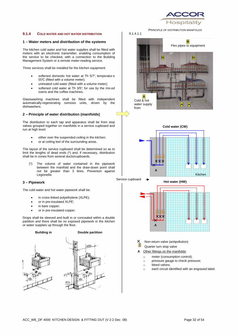
ACC_WE_DF 4000 KITCHEN DESIGN & FITTING OUT (V 2-2 Dec 08) Page 32 of 54
PRINCIPLE OF DISTRIBUTION MANIFOLDS
9.1.4 COLD WATER AND HOT WATER DISTRIBUTION 1 – Water meters and distribution of the systems The kitchen cold water and hot water supplies shall be fitted with meters with an electronic transmitter, enabling consumption of the service to be checked, with a connection to the Building Management System or a remote meter-reading service. Three services shall be installed for the kitchen equipment:
• softened domestic hot water at Th 5/7°, temperatur e 55°C (fitted with a volume meter);
• untreated cold water (fitted with a volume meter); • softened cold water at Th 3/5°, for use by the mix ed
ovens and the coffee machines. Glasswashing machines shall be fitted with independent automatically-regenerating osmosis units, driven by the dishwashers. 2 – Principle of water distribution (manifolds) The distribution to each tap and apparatus shall be from stop valves grouped together on manifolds in a service cupboard and run at high level:
• either over the suspended ceiling in the kitchen; • or at ceiling leel of the surrounding areas.
The layout of the service cupboard shall be determined so as to limit the lengths of dead ends (*) and, if necessary, distribution shall be in zones from several ducts/cupboards. (*) The volume of water contained in the pipework
between the manifold and the draw-down point shall not be greater than 3 litres. Preventon against Legionella
3 – Pipework The cold water and hot water pipework shall be:
• in cross-linked polyethylene (XLPE); • or in pre-insulated XLPE; • in bare copper; • or in pre-insulated copper.
Drops shall be sleeved and built in or concealed within a double partition and there shall be no exposed pipework in the kitchen or water supplies up through the floor.
Building in Double partition
9.1.4.1.1
PRINCIPLE OF DISTRIBUTION MANIFOLDS
Cold water (CW)
Hot water (HW)
Non-return valve (antipollution)
Quarter turn stop valve
A Other fittings on the manifolds:
o meter (consumption control); o pressure gauge to check pressure; o bleed valves; o each circuit identified with an engraved label.
A
A
Service cupboard
Kitchen
A A
B
B
A Cold & hot water supply from
B Flex pipes to equipment

ACC_WE_DF 4000 KITCHEN DESIGN & FITTING OUT (V 2-2 Dec 08) Page 33 of 54
4 – Requirements – Pressurised water systems
• Pressure reduction valves shall be installed if necessary so that the working pressure of the cold water and hot water distribution remain between 2.5 and 3.5 bar at draw-off points.
(This pressure shall not be exceeded on XLPE pipework, which may be subjected to thermal shock at 70°C).
• Cold water pipework subject to a risk of condensation
(particularly above suspended ceilings) shall be pre-insulated or lagged.
• Hot water pipework shall always be pre-insulated or
lagged.
• The lagging shall be classified as "non-inflammable"
• Pipework chased in shall be run in continuous sleeves and shall have no joints in its length.
• Workmanship shall comply with the manufacturer's
instructions and standards. 5 – Connection of the equipment Each individual connection shall terminate at a wall-mounted recessed elbow connection with a threaded socket to enable a tap or a hose for the connection of an item of equipment to be fixed. When the point to be fed has 1 cold water + 1 hot water point, the two connections shall be grouped together on a recessed fixing plate. In general, any supply point shall be fixed onto supports recessed into walls, of a type as specified by the manufacturer. 6 – Limits to the extent of works The taps to sinks and pot-washes shall not be fixed to the fittings, but shall all be of the wall-mounted type. They shall generally be provided by the kitchen equipment contractor and fixed by the plumbing contractor. The hoses for connecting the kitchen equipment and the hand rinse basins to the plumbing services shall be supplied and fixed by the kitchen equipment contractor. 9.1.5 KITCHEN WASTE WATER DRAINAGE 1 Design of the drainage systems PRIMARY VENTILATION The waste stacks shall be vented at roof level above occupied areas in order to ensure the proper flow of water, the maintenance of water seal in traps and the ventilation of systems and drains. When a system has main pipes in branches that are not connected to ventilated stacks, primary ventilation stacks shall be formed at the top of these main pipes.
VENTILATION OF THE APPLIANCE WASTES Secondary ventilation will not be required throughout, but it shall be provided when necessary for the correct operation of the installation. This concerns drain runs that serve more than 4 or 5 appliances and must therefore be treated as main drain runs. SEPARATION OF THE SYSTEMS The kitchen waste drainage system shall be kept separate from other waste systems and fitted with a grease trap located before its connection to the common system. PROTECTION AGAINST BACKFLOW FROM THE DRAINS As the external drains are capable of being full of water up to the level of the roadway, if the installations are at a lower level than the road, the wastes shall be run to a sump pump and the outflow pipework, with its non-return valve, shall be run in a crosshead going above the level of the road. 2 Waste drainage systems The drains serving the kitchen and its associated zones, from the floor gullies and channels down to the grease trap shall be capable of resisting very hot water and the corrosiveness of water containing detergents. The main pipework shall be in polyethylene or in non-corroding cast iron, with elastomer gaskets and straps and hangers. (Or special gaskets on underground systems). No section of these systems shall be run in a diameter of less than 100 mm. The falls shall be set at ≥ 3% and rodding eyes shall be provided at changes in direction and every 3 m. The runs of pipework in an unheated basement shall be lagged so that grease does not solidify and, if necessary, a self-regulating electrical tape shall be used to maintain the temperature. The tops of the ventilation pipes shall project above roof level as primary ventilation outlets, in non-flammable PVC pipework. If the drains are run underground, inspection chambers with stainless steel air-tight covers shall be provided.
highway
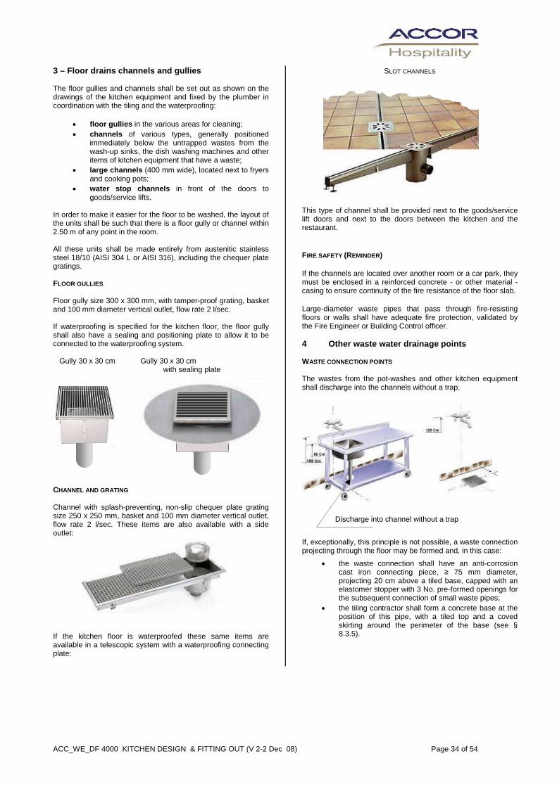
ACC_WE_DF 4000 KITCHEN DESIGN & FITTING OUT (V 2-2 Dec 08) Page 34 of 54
3 – Floor drains channels and gullies The floor gullies and channels shall be set out as shown on the drawings of the kitchen equipment and fixed by the plumber in coordination with the tiling and the waterproofing:
• floor gullies in the various areas for cleaning; • channels of various types, generally positioned
immediately below the untrapped wastes from the wash-up sinks, the dish washing machines and other items of kitchen equipment that have a waste;
• large channels (400 mm wide), located next to fryers and cooking pots;
• water stop channels in front of the doors to goods/service lifts.
In order to make it easier for the floor to be washed, the layout of the units shall be such that there is a floor gully or channel within 2.50 m of any point in the room. All these units shall be made entirely from austenitic stainless steel 18/10 (AISI 304 L or AISI 316), including the chequer plate gratings. FLOOR GULLIES Floor gully size 300 x 300 mm, with tamper-proof grating, basket and 100 mm diameter vertical outlet, flow rate 2 l/sec. If waterproofing is specified for the kitchen floor, the floor gully shall also have a sealing and positioning plate to allow it to be connected to the waterproofing system. Gully 30 x 30 cm Gully 30 x 30 cm with sealing plate CHANNEL AND GRATING Channel with splash-preventing, non-slip chequer plate grating size 250 x 250 mm, basket and 100 mm diameter vertical outlet, flow rate 2 l/sec. These items are also available with a side outlet: If the kitchen floor is waterproofed these same items are available in a telescopic system with a waterproofing connecting plate:
SLOT CHANNELS This type of channel shall be provided next to the goods/service lift doors and next to the doors between the kitchen and the restaurant. FIRE SAFETY (REMINDER) If the channels are located over another room or a car park, they must be enclosed in a reinforced concrete - or other material - casing to ensure continuity of the fire resistance of the floor slab. Large-diameter waste pipes that pass through fire-resisting floors or walls shall have adequate fire protection, validated by the Fire Engineer or Building Control officer. 4 Other waste water drainage points WASTE CONNECTION POINTS The wastes from the pot-washes and other kitchen equipment shall discharge into the channels without a trap.
Discharge into channel without a trap
If, exceptionally, this principle is not possible, a waste connection projecting through the floor may be formed and, in this case:
• the waste connection shall have an anti-corrosion cast iron connecting piece, ≥ 75 mm diameter, projecting 20 cm above a tiled base, capped with an elastomer stopper with 3 No. pre-formed openings for the subsequent connection of small waste pipes;
• the tiling contractor shall form a concrete base at the position of this pipe, with a tiled top and a coved skirting around the perimeter of the base (see § 8.3.5).

ACC_WE_DF 4000 KITCHEN DESIGN & FITTING OUT (V 2-2 Dec 08) Page 35 of 54
WASTES TO HAND RINSE BASINS The plumber shall form the wastes to the hand rinse basins in polyethylene or copper pipework with all necessary bends and fittings to connect them to the traps of the basins. The vertical copper waste shall be sleeved and built into the wall or concealed within a double partition and shall be connected to the main waste water pipes under the kitchen. AIR VENT BACKFLOW PREVENTION (OPEN AT GAP ON WASTES ) Certain items of equipment may require an air-vented waste. This shall comprise a trapped tundish (Y shape) which shall be surface-fixed to a wall using isolating collars. It shall be connected to the cast iron waste pipe provided by others, projecting from the floor. 9.1.6 GREASE TRAP 1 – Sizing The size of the grease trap shall be determined to suit various factors:
• the number of meals per day handled by the kitchen; (Breakfast being counted as half a meal) • daily flow rate of the effluent to be treated; • peak flow rate; • temperature of the effluent; • whether detergents are present; • frequency of emptying, maximum 4 times per year;
(the supplier shall guarantee proper operation at this frequency) • sanitary rules applicable in the location.
Depending on the type of apparatus, the contractor shall determine the characteristics by a calculation in accordance with European standard EN 1825-2 or in accordance with the equipment manufacturer's specific data. 2 – Selection of the type of grease trap
(See documentation in A PPENDIX B)
The apparatus selected shall have a purification efficiency greater than 90% and may be installed:
• Internally
A – Traditional grease trap B – Self-cleaning trap with skimmer
• Internally, below the kitchen level
C – Traditional trap (concrete or polyethylene)
3 – Grease trap fixed internally (A or B)
• The apparatus may be of the type:
A – Traditional grease trap with strainer basket Sized by the calculation in accordance with standard EN 1825.2 Manufactured in steel, protected against corrosion, B - Self-cleaning trap with skimmer
Recommended whenever possible Sized in accordance with the manufacturer's data Manufactured in austenitic stainless steel • In either cases, the apparatus shall be installed in a
dedicated plant room below the kitchen level and shall be accessible for routine maintenance.
• A straight sleeve shall be provided to allow access for the suction hose for the grease pumping lorry.
• The ventilation pipe from the apparatus, in non-flammable PVC, shall project above roof level.
4 – Underground grease trap externally (C) Separate units with inspection chamber on outlet
Single-unit apparatus A Strainer basket B Separator C Raising piece (frost protection)
• The equipment shall be buried in a location accessible to the emptying vehicle.
• It may be constructed from lightweight concrete or polyethylene.
• The covers shall be capable of withstanding the rolling load of the lorries that come into the service courtyard (> 19000 Kg)
• Raising pieces of an appropriate height shall be provided, so that the units can be buried at the required depth, depending on the risk of frost locally.
Primary ventilation pipework shall be provided, in order to prevent the risk of smells.
A B
C C
A B
C

ACC_WE_DF 4000 KITCHEN DESIGN & FITTING OUT (V 2-2 Dec 08) Page 36 of 54
9.2 GAS DISTRIBUTION IN THE KITCHEN A gas supply from the public main or from a gas tank shall generally be provided for the kitchen if it is possible and if it is not forbidden under local building regulations. The gas connection shall include a meter and a pressure regulator. From the gas valve provided at the pressure regulator, the installation shall comprise:
Outdoor
• the connection to the valve; • manual emergency stop valve in a glass-fronted
cabinet, with a clearly-visible indicator panel located in a position accessible to the fire brigade, before the entry of the gas into the building; (externally).
Indoor
• gas pipework inside the building up to the kitchen; • manual stop valve located in an accessible and
visible position, with an indicator panel, positioned at the point of entry of the gas into the kitchen;
• distribution of the gas in the ceiling and built-in drops in sleeves in the walls, in copper tubing, up to the various items of equipment. The tails to each item of equipment shall have visible and accessible stop valves.
• painting of the pipework in the conventional colour and indicator panels.
Horizontal pipework shall preferably be run visible, surface mounted below suspended ceilings . If it has to be run above ceilings, suspended ceiling voids in which the gas pipework is run shall have ventilation grilles. Pipework built into walls shall be protected by a protection sleeve and shall be in a single length, with no connections or welds, and shall be marked and identified with engraved plates. If the gas pipework passes through another room, it shall be protected by a duct or casing with a REI 60 fire rating, the ends of which shall be left open in order to ventilate the duct. Gas pipework shall not be run through car parks. If it is inevitable, it shall be enclosed in a vented duct to provide fireproofing and mechanical protection. If gas is also provided for requirements other than those of the kitchen, individual sub-metering shall be provided on the gas supply to the whole of the kitchen. The gas installation shall comply with the country's safety rules and should preferably include, in all cases, gas detection in the kitchen and, if necessary, a valve linked to that detection. All visible and non visible gas pipes shall be painted yellow (or other colour as per local codes).

ACC_WE_DF 4000 KITCHEN DESIGN & FITTING OUT (V 2-2 Dec 08) Page 37 of 54
A B
9.3 VENTILATION AND AIR CONDITIONING OF THE KITCHEN ZONE 9.3.1 VENTILATION OF THE ROOMS 1 – Components of the installations
• Extract hoods required o Over the cooking range in the cooking zone o Over ovens (kitchen and patisserie) o Over the dishwashing machines • Extraction system from the above hoods and
branches and extract grilles in partitioned or remote associated areas
• Fresh air make-up equipment comprising, depending on the size of the kitchen and the climatic conditions of the site:
o one external air intake, open directly onto the kitchen; o one external air intake, a fan and a system of ducts to
the hood; o an air handling unit, supply air ducts and diffusers,
independent or on the hoods.
• Mechanical ventilation of stores 2 – Guidelines The design of the kitchen ventilation shall be coordinated with that of the air-conditioning of the hotel, in order to avoid nuisances: acoustic and smells. The kitchen shall be kept at negative pressure in relation to the remainder of the hotel. The fresh air shall be supplied to the kitchen by an air treatment installation, which shall compensate for the extracted air, while still maintaining the negative pressure. (Compensation by the transfer of air from the restaurant will only be permitted under particular circumstances). Induction hoods or capture jet hoods shall be favoured in order to improve the efficiency of capture and to save energy. The treated air shall be supplied to the kitchen areas, in such a way that it provides good cross ventilation with extract hoods.. The installation shall operate, depending on circumstances:
• small installations, dishwashing, pantries: o at 2 speeds, controlled manually by the chef from a
switch in the kitchen (positions off - speed 1 - speed 2);
• cooking zone: o at a variable speed, controlled by a programmer / time-
clock, with the possibility of manual override. A system for the management of fumes and temperatures shall be installed in the hoods of large kitchens, in order to ensure the automatic management of the fans and extracts depending on the level of activity. The system shall take into account changes in temperature and shall manage the extract and make-up air flow rates proportionally, as in the “Intelli Hood / Gestion’air systems” (These systems shall also be capable of being controlled manually).
See APPENDIX E
The hoods over the dishwashing zone shall be left running permanently at low speed when the kitchen is no longer being used. PARTICULAR CASE OF OPEN KITCHEN
In the case of a kitchen open onto a restaurant, the installation may also need to provide smoke extraction in the event of fire (subject to local codes and design of Fire engineer). PARTICULAR CASE OF AIR TRANSFER The transfer of air from an adjacent room will be permitted for pantries and small reheating kitchens where the extract flow rate is considerably lower than in a BIG kitchen. In this case, a transfer grille shall be provided, fitted with a fire damper linked to the fire detection and an aco ustic buffer. A Acoustic ducting
B Fire damper 2 – Comfort criteria in the kitchen
• Ambient temperatures shall be > 19°C in winter < 27° C in summer.
• Air flow speed in the kitchen: ≤ 0.3 m/sec. 3 – Extract flow rates from the hoods
See APPENDIX C
4 – Permanent ventilation A kitchen is a very humid room, in which heat is given off continuously (motors of refrigerated units) and in which there is always a characteristic smell. It is necessary to provide permanent ventilation, programmed by a weekly time-clock, to ensure air changes and to maintain the negative pressure in relation to other areas. All the areas are affected.
• Main kitchen • Pantries • Stores • Rubbish rooms
THE MAIN KITCHEN AND ITS ASSOCIATED AREAS In order to ensure sufficient air changes when the kitchen is not being used, an air change rate of 1.5 volumes per hour minimum shall be provided. This extraction shall be provided by the permanent low speed of the dishwashing hood and the intermittent operation of the cooking range hood. The fresh air supply rate shall be maintained at reduced speed. The kitchen shall always be maintained at negative pressure in relation to other areas.
Kitchen Restaurant

ACC_WE_DF 4000 KITCHEN DESIGN & FITTING OUT (V 2-2 Dec 08) Page 38 of 54
THE OTHER AREAS The ventilation of these areas shall generally be connected to the hotel's extraction system, with an air change rate of 2 volumes / hour. These rates may be increased to allow for heat sources (in relation to the volume of each room). Air may be extracted from some areas by transfer through openings in these areas onto adjacent rooms or corridors, provided that the extraction is correctly located opposite the air inlet, so that complete air changes can be ensured. 9.3.2 EXTRACT HOODS 1 – Principle of the hoods The extract hoods shall be designed either by the air-conditioning designer or by the manufacturer of the hoods to suit kitchen equipment.
They shall be entirely in austenitic stainless steel sheet ≥ 1.0 mm thick, brightly polished, fixed to galvanised steel structures, and shall comprise;
• a gutter to collect condensates and grease; • filters; • internal lighting.
If the kitchen has a suspended ceiling, the hood shall have a flange at the top, to butt up against the suspended ceiling. DIAGRAM OF A HOOD a Lighting
b Automatic fire suppression system (over fryers and range)
c Gutter to collect condensation and grease
d Air speed at the entry to the hood of between 0.25 and 0.50 m/sec, depending on equipment.
e Height between the floor and the hood: > 1,9 and < 2 metres. Over certain items of equipment such as ovens, the height may be increased to 2.20 m.
f Projection of the hood beyond the units:
o Hobs: ≥ 30 cm o Ovens:
� at front ≥ 50 cm � at sides ≥ 30 cm
o Dishwasher * � without casing ≥ 90 cm � with casing ≥ 40 cm
The hood shall be as shallow as possible in height so as to absorb the mixture of fumes and steam as an oven or a fryer is opened. The filters shall be at the top of the hood so that there is no unventilated zone above the filters. 2 – Types of hoods
See principles in APPENDIX D
The selection of the particular type of hood is an essential point in the design of the ventilation of kitchens. It will depend on the characteristics of the kitchen and on the climatic conditions in the locality.
A joint study by the kitchen consultant and the air-conditioning consultant shall justify the solutions proposed, stressing the various parameters (Operation, comfort, capital cost, energy costs).
• A – Simple hood (wash-up, pantry, small kitchens)
• B – Compensation hood – Natural air or treated air
• C – Induction hood, natural or reheated air (when risk of condensation)
• D – Induction and compensation hood, treated air
• E – Capture jet and compensation hood on external wall
c
f
e
d
b a
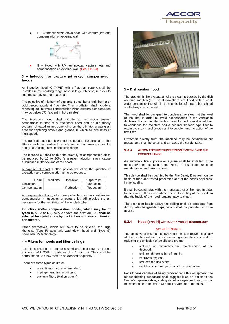
ACC_WE_DF 4000 KITCHEN DESIGN & FITTING OUT (V 2-2 Dec 08) Page 39 of 54
• F – Automatic wash-down hood with capture jets and
compensation on external wall
• G – Hood with UV technology, capture jets and compensation on external wall (See § 9.3.4)
3 – Induction or capture jet and/or compensation hoods An induction hood (C TYPE) with a fresh air supply, shall be installed in the cooking range zone in large kitchens, in order to limit the supply rate of treated air. The objective of this item of equipment shall be to limit the hot or cold treated supply air flow rate. This installation shall include a reheating coil to avoid condensation when external temperatures may go below 5°C (except in hot climates). The induction hood shall include an extraction system comparable to that of a traditional hood and an air supply system, reheated or not depending on the climate, creating an area for capturing smoke and grease, in which air circulates at high speed. The fresh air shall be blown into the hood in the direction of the filters in order to create a horizontal air curtain, drawing in smoke and grease rising from the cooking range. The induced air shall enable the quantity of compensation air to be reduced by 10 to 20% (a greater induction might cause turbulence in the volume of the hood). A capture jet hood (Halton patent) will allow the quantity of extraction and compensation air to be reduced.
Hood Traditional Induction Capture jet Extraction Reduction Compensation Reduction Reduction A compensation hood, which may also be used in combination: compensation + induction or capture jet, will provide the air necessary for the ventilation of the whole kitchen. Induction and/or compensation hoods, which may be o f types B, C, D or E (See § 2 above and APPENDIX D), shall be selected by a joint study by the kitchen and air-co nditioning consultants. Other alternatives, which will have to be studied, for large kitchens: (Type F) automatic wash-down hood and (Type G) hood with UV technology. 4 – Filters for hoods and filter ceilings The filters shall be in stainless steel and shall have a filtering efficiency of ≥ 95% of particles of ≥ 8 microns. They shall be demountable to allow them to be washed frequently. There are three types of filters:
• mesh filters (not recommended), • impingement (impact) filters, • cyclonic filters (Halton patent).
5 – Dishwasher hood The problem is the evacuation of the steam produced by the dish washing machine(s). The dishwashers are fitted with a cold-water condenser that will limit the emission of steam, but a hood shall always be provided. The hood shall be designed to condense the steam at the level of the filter in order to avoid condensation in the ventilation ductwork. It shall be fitted with a panel formed from shaped bars to condense the moisture and a second "Impact" type filter to retain the steam and grease and to supplement the action of the first filter. Extraction directly from the machine may be considered but precautions shall be taken to drain away the condensate. 9.3.3 AUTOMATIC FIRE SUPPRESSION SYSTEM OVER THE
COOKING RANGE An automatic fire suppression system shall be installed in the hoods over the cooking range zone. Its installation shall be mandatory when there is a fryer. This device shall be specified by the Fire Safety Engineer, on the basis of tried and tested processes and of the codes applicable in the locality. It shall be coordinated with the manufacturer of the hood in order to incorporate the device above the metal ceiling of the hood, so that the inside of the hood remains easy to clean. The extinction heads above the ceiling shall be protected from dirt by interchangeable caps, which shall be provided with the device. 9.3.4 HOOD (TYPE H) WITH ULTRA VIOLET TECHNOLOGY
See APPENDIX C
The objective of this technology (Halton) is to improve the quality of the discharged air by eliminating grease deposits and by reducing the emission of smells and grease:
• reduces or eliminates the maintenance of the ductwork;
• reduces the emission of smells; • improves hygiene; • reduces the risk of fire; • enables optimum operation of the ventilation.
For kitchens capable of being provided with this equipment, the air-conditioning consultant shall suggest it as an option to the Owner's representative, stating its advantages and cost, so that the selection can be made with full knowledge of the facts.

ACC_WE_DF 4000 KITCHEN DESIGN & FITTING OUT (V 2-2 Dec 08) Page 40 of 54
9.3.5 FILTER CEILINGS There are two types of filter ceilings: 1 – Open filter ceiling An open filter ceiling extracts air in bulk in the void between the ceiling and the slab. As an alternative, it can be divided into several ceiling voids covering large areas. This technique is to be avoided as it causes numerous maintenance and hygiene problems. 2 – Closed filter ceilings All the extract points are connected to the extraction system. This design facilitates maintenance, guarantees hygiene and distributes flow rates evenly. 3 – Why selecting a “ventilated ceiling” ? Normally, this choice should not be considered for an enclosed kitchen, but it may be of interest for a kitchen or a kitchen zone visible to the public (display kitchen). In any case, it shall be subject to a particular study to justify this choice, bearing in mind that the initial capital cost is greater than hoods and that there are operation constraints for cleaning (resulting in higher operation costs).
9.3.6 REGULATION OF THE EXTRACTION FLOW RATE
See APPENDIX D For large installations (+ 10 kW) a MELINK-type automatic extraction flow rate regulation system may be of functional and financial interest. It shall be proposed by the consulting engineer for the large installations that justify it. 9.3.7 VENTILATION DUCTWORK SYSTEM 1 – Ventilation ductwork The extract ductwork from the hood over the cooking range shall be made from black iron sheet ≥ 2 mm thick, with welded joints, perfectly air-tight and protected externally against corrosion. The other extract ductwork and the air supply ductwork shall be made from galvanised steel. The ducts may be of circular section or rectangular section (ratio L /l < 2/1). The extract ductwork shall not be lagged; the supply air ductwork shall be lagged if necessary, depending on the climatic conditions of the site. 2 – Air speed The air speed in the extraction ductwork shall be limited by design as follows:
• Supply air ≤ 4 m/second • Extract ≤ 6 m/second
3 – Fire safety of ventilation ductwork There shall be no fire dampers in the hood extraction system. This means that the extract duct shall be fixed inside a vertical fire-resisting duct, constructed with the structure of the building, and that the horizontal run of the duct shall have a protective casing that is fire-resisting in both directions (possible fire inside or outside the duct). 4 – Inspection covers in the extract ductwork In order to permit cleaning, an airtight, easily-removable inspection cover shall be provided:
• at the bottom of vertical lengths of duct, with a residue collector;
• and, on horizontal runs, every 3 metres and at each change of direction of more than 30°.
If the horizontal run of ductwork is outside the kitchen, the inspection cover shall be a double cover, with a fire-resisting cover fixed on the casing.

ACC_WE_DF 4000 KITCHEN DESIGN & FITTING OUT (V 2-2 Dec 08) Page 41 of 54
9.3.8 EXTRACT AND AIR DISCHARGE FANS 1– Kitchen fan The extract ductwork shall be kept at negative pressure for its full length. A fan located on the roof shall be preferred to a box or turbine located along the run of the extract duct. Criteria to be taken into account:
• vertical-jet two-speed or variable-speed fan; • ease of cleaning the assembly: access to the fan and
dismantling of its various parts; • noise level of the equipment compatible with its
environment; • local switch for safety of maintenance.
If it is not possible to install a rooftop fan, the extraction unit shall be located as close as possible to the discharge grille. A weatherproof electrical panel shall be provided for the supply, protection, remote controls. All equipment located outdoors shall have an anti-corrosion treatment with an epoxy paint finish, and fixing accessories and bolts shall be in stainless steel.
2 – Dishwashing extract fan The extract fan from the dishwashing hood shall be independent from that from the kitchen. It shall have the same characteristics. 3 – Air discharge The location of the discharge (always at the top of the building) shall be determined to take into account:
• Prevailing winds, that risk driving back smells and creating smell problems for the hotel guests or for neighbours;
• Fresh air inlets (which should not be less than 8 m from the discharge);
• Avoidance of possible damage or inconvenience to neighbouring buildings.
If there is a discharge grille, it shall have anodised or lacquered aluminium rain-proof blades and shall be removable for cleaning. This grille shall be compatible with the air discharge speed so that it does not cause any noise problems (whistling or vibration). 4 – Energy recovery on kitchen extract systems Energy recovery on kitchen extracts may be included subject to project particulars and based on a feasibility study. It may include plate heat exchangers or heat pumps systems installed :
• On the extract to the dishwasher, or • On the general kitchen extract (preferably if extract is
fitted with ultra-violet system to reduce grease deposits– see 9.3.4)
Energy recovered may be used for heating air supply. The consulting engineer shall provide calculations to ensure that the energy recovery is satisfactory in the light of the temperatures (relatively low) and of the build-up of grease or deposits on the coils installed on the extract system
9.3.9 MAKE-UP AIR SUPPLY 1- Principle Particular attention shall be paid to compensation. Incorrectly-sized or badly-positioned diffusers may create drafts and limit the effectiveness of hoods of filter ceilings. (Low-speed compensation on the front of the hoods deals well with this problem) The installation shall comprise:
• a fresh air inlet system on the outside of the building; • an air handling unit (supply air only); • a system of supply air ducts and diffusers above
suspended ceiling. The operation of this unit shall be inter-linked to the operation of the extraction system. For induction hoods, there shall normally be a double make-up air installation:
• natural air or heated air, if necessary, for the inside of
the hood (induction or capture jets); • treated air for compensation (on the hood or spread
through the kitchen); • mobile louvered grilles on the external wall (if the
climate is suitable). The diffusers shall be designed to limit the residual air speed at any workstation to ≤ 0.3 m/sec. 2 Air handling units Note – Refer to the brand's "Air-conditioning" technical requirements concerning:
• the air handling unit: • fire safety in the unit; • the controls of the unit; • the electrical panel or distribution board; • the controls of the ventilation installation

ACC_WE_DF 4000 KITCHEN DESIGN & FITTING OUT (V 2-2 Dec 08) Page 42 of 54
9.3.10 COOLED AREAS 1 - Treatment of the cold preparation zone Compliance with the cold chain means that "cold preparation" food must be kept at an internal temperature of less than 10° C.
In order to maintain this internal temperature when cutting, slicing and preparing food, it shall be essential to cool these working zones. A cooling installation shall be provided that will ensure keeping a temperature set by a room thermostat below ≤ 17°C in:
o vegetable preparation, o butchery, o fish preparation, o cold preparation areas.
Note : Under the regeneration process, food may be prepared 1 or 2 days before serving. In such case, the room where food is prepared (including food cutting, plate dressing) must be maintained below 12°C. Prepared food must then be s tored in cold rooms below 3°C.
Each system shall be direct expansion type and shall comprise:
• an independent low-speed air/air "refrigerator" type evaporator for these areas (wall-mounted rather than ceiling-mounted, so that filters can be changed easily);
• connection of the condensates to a drain; • external "condenser" units, the locations of which
shall be selected to ensure correct operation and to avoid noise problems for the surrounding areas;
• a thermostat and control box in each room involved; • connection pipework and cabling between the indoor
and outdoor units, lagging and accessories. • It will not be allowed to cool these rooms out of the
main hotel chilled water distribution. 2 Treatment of the organic rubbish room In addition to its ventilation, whether natural or mechanical depending on circumstances, an air/air split system "refrigerator" direct expansion type unit shall be installed, in order to guarantee a maximum temperature of:
• 12°C in hot countries; • 16°C in temperate and cold countries.
Same principle of unit as at §1above.
9.3.11 SMOKE EXTRACTION FUNCTION VIA THE KITCHEN HOOD
This function is essential for kitchens open onto the restaurant and may also be required in enclosed kitchens by the country's safety codes or in accordance with the requirements of the Fire Safety Engineer. RECOMMENDED ARRANGEMENTS :
• the hood over the cooking range shall provide smoke extraction;
• the fan shall be able to run for one hour at 400°C ; • the ductwork shall be in non-combustible materials;
• the electrical cables supplying the fans shall be fire-resistant and shall originate at the main safety distribution board backed up by the replacement of electrical source (generator or UPS); • the emergency stop devices (electrical power and gas
cut-off) shall not interrupt the operation of the extract fan;
• a manual "smoke extraction" control shall be provided in an accessible location and identified by an indelible panel;
• any other necessary arrangements (possible inter-link to the main fire panel), in accordance with the local safety codes, or as specified by the Fire Safety Engineer.
9.3.12 NATURAL SMOKE EXTRACTION FROM THE KITCHEN If the kitchen is located under a roof and smoke extraction has to be provided, this can be provided by outlets at high level. In this case, the fresh air supply shall be via opening panels in the external walls. The outlets and the opening sections shall be fitted with screw openers, which shall be controlled manually from a single point, accessible and identified with an engraved sign. The area of the openings (approximately 1/100th of the area of the room) and any other necessary arrangements (possible inter-link to the main fire panel), in accordance with the local safety codes, or as specified by the Fire Safety Engineer.

ACC_WE_DF 4000 KITCHEN DESIGN & FITTING OUT (V 2-2 Dec 08) Page 43 of 54
9.3.13 OPEN FIREPLACE In the case of an open fireplace for a grill or for decoration (which may exist in some restaurants), a particular study will be needed to ensure the safety and the proper operation of the ventilation.
This installation will only be possible if the local codes permit it.
The flue may have a natural or mechanical draft depending on the layout of the building.
A natural or mechanical supply of fresh air to the fireplace shall be provided in order to ensure proper operation. The flue must be:
• vertical, with no changes in direction in its height; • constructed from non-combustible materials; • located and thermally insulated so that, in the event
of a flue fire, the internal structure of the building is not heated;
• extended to a sufficient height above the building and nearby roof extensions;
• easy to sweep under proper safety conditions for staff.
In the case of mechanical ventilation, the fan shall be resistant to fumes at 400°C for one hour and shall have an emerg ency electrical supply
If a change of direction is unavoidable at the bottom of the flue, mechanical ventilation must be used
If a change of direction is unavoidable at the bottom of the flue, mechanical ventilation must be used.
9.4 KITCHEN ELECTRICITY
9.4.1 GENERAL REQUIREMENTS The electrical installation shall comply with applicable safety standards in respect of the public and of workers, concerning, in particular:
• the separation of the circuits for public areas from those of service areas;
• the separation of lighting circuits from power circuits; • earthing; • residual current circuit breakers; • emergency switches; • emergency lighting.
Supply voltage in accordance with international standards (except USA and other countries with a different standard):
• 3 Phase + N 230/400 V - 50 Hertz; • 230 V or 240V - for "lighting" and "Power outlets"
circuits; • 400 V or 410 V for the "power" circuits.
The maximum voltage drop between the origin of the MV installation and the furthest user points shall not exceed:
• < 3% for the "lighting" and "socket outlet" circuits; • < 5% for the "power" circuits.
The power load calculation shall be established for the whole of the hotel, including the kitchen equipment, making allowance, without excess, for appropriate simultaneity factors according to the possible total demand at different times of the day. The wiring in the kitchen zones shall be run:
• horizontally, on cable trays located above the suspended ceilings or in conduits cast into the concrete ceiling slab, if there is no suspended ceiling;
• vertically, in conduits cast into walls, and on cable trays in service ducts.
(Only store rooms may have an exposed electrical distribution in plastic conduit fixed on collars with plastic connectors and tees.) The cable trays shall be made from welded galvanised mesh and shall be positioned in such a way that they are accessible for maintenance (particularly junction boxes). They shall include 30% spare capacity for possible additions. The cables shall be aligned and fixed to the cable trays. (No bunched cables.)
« Courte Paille » Fire place

ACC_WE_DF 4000 KITCHEN DESIGN & FITTING OUT (V 2-2 Dec 08) Page 44 of 54
9.4.2 KITCHEN ELECTRICAL DISTRIBUTION The neutral regime shall be determined by the consulting engineer by application of the country's standards and codes and, in all cases, protection by means of a differential residual current device and selectivity shall be ensured. Earthing shall be provided for the electrical distribution boards, cable trays, tails for "power" installations, light fittings, socket outlet bases, hoods, metal frames, suspended ceilings and their structures and, in a general way, for all metal masses likely to become live. If the hotel has a replacement power source, the circuits with normal supplies (N) shall be kept separate from those with a normal and emergency supply (NS). For the kitchen, the replacement supplies shall include:
• For the replacement function: o refrigerators and freezers; o lighting; o kitchen equipment, if applicable
(depending on the reliability of the public main).
• For the safety function: o mechanical smoke extraction (see above).
9.4.3 "POWER" ELECTRICAL DISTRIBUTION BOARDS AND
PANELS Depending on the layout of the main kitchen and the pantries or other associated areas, a single kitchen power distribution board may be provided, or one main board and other boards or panels serving remote items of equipment. This waterproof cabinet, with a lockable door, shall be located inside a small room or a cupboard with a fire-resisting door. For small kitchens or pantries, the sealed cabinet or panel may be located within the room, in a recess or in a passage as far away from impact and damp as possible. The "power" compartments shall not be grouped together with the lighting circuits, which shall be connected to the nearest secondary distribution boards.
PRINCIPLE OF EQUIPMENT
• Meters with an electronic transmitter connected to the BMS
o General meter for the electrical consumption of the kitchen installations
o Maximum load meter, with reset to 0
• Sets of bus bars protected with plastic screens • Earthing • Main switch • ”Push” type emergency shutdown • Main circuit breaker • Live current warning lamp (LEDs) • Residual current circuit breakers protecting each
circuits • "Lamp test" button • Engraved and riveted circuit and sub-circuit
identification labels • Wiring diagram in pocket inside the door
The appliances shall be protected individually using residual current circuit breakers. The origins of the circuits on the bus bars shall be arranged per room or per zone, leaving spare space of 20% on the end of each series of outlets for the possible subsequent addition of items of equipment. Each outlet shall be identified with an engraved label. EMERGENCY SWITCHES
In each room, "push" type emergency stop buttons, reset by key, shall be provided on the cabinet (or panel), at the entrance door and close to the main workstations (cooking range, dishwashing machines, pastry), in locations not exposed to accidental impacts. Each emergency stop button in a room or zone shall cut off all the power supplies, without selectivity (but shall not switch off lighting).
ALARM REPEATER
A repeater alarm shall be sent from the kitchen distribution board to the technical alarm panel to indicate cold room faults and rises in temperature. LOAD SHEDDING
Depending on the power levels installed and the power levels available in normal and/or emergency running, an automatic, selective load-shedding system, with simple or cyclical cut-off, may be necessary. This system shall be designed on a case by case basis using an operational use scenario. 9.4.4 SUPPLIES TO THE KITCHEN EQUIPMENT 1 – Kitchen equipment The electrical connections shall be listed on the kitchen equipment drawings prepared by the kitchen consultants; The supplies shall be from ceiling level, with drops in conduits recessed into walls. The tails shall be three-phase+N+E type or single-phase+E type and shall include, depending on circumstances:
• a sealed terminal box, built in approximately 50 cm above floor level, with a cable outlet at the bottom, with a gland;
• a sealed terminal box with an isolating switch, built in approximately 140 cm above floor level, with a cable outlet at the bottom, with a gland.

ACC_WE_DF 4000 KITCHEN DESIGN & FITTING OUT (V 2-2 Dec 08) Page 45 of 54
Cables approximately 2 m long, provided to connect the equipment to the terminal boxes, shall first be fixed to the equipment (unconnected cables, which may become live, must not be supplied). 2 – Small fittings The socket outlets, switches, push-buttons, indicator lamps, etc. shall be waterproof (IP : 4/4) and in an unbreakable material, metal or polycarbonate, with screw fixings. They shall generally be recessed. In the stores zones, they may be surface-mounted. 3 – Particular case of cold rooms Depending on the location of the compressors, the cold rooms may be fed either directly from the main distribution board or from the kitchen board. In all cases, they shall be fed from circuits backed up by the replacement source. 4 – Sundry other supplies The independent air-conditioning units in the cooled kitchen zones shall be fed from the kitchen "power" panel. The kitchen supply and extract fans shall be fed directly from the hotel's main medium-voltage distribution board. 9.4.5 LIGTH FITTINGS IN THE KITCHEN ZONES
Light fittings shall be distributed so as to obtain average lighting levels, with no low points less than 75% of the average level.
All fluorescent light fittings shall have electronic ballast (Accor sustainable development rules). Fluorescent light sources shall have a colour temperature of 3000°K. Light fittings shall comply with the standards for water-tightness, impact- and temperature- resistance, and fire-rating, depending on the room and the location where they are fixed. They shall be supplied complete with accessories, trim, fixings and lamps. Those built into suspended ceilings shall include their hangers and soffit fixings, independent of the ceilings' framework and hangers. The lighting controls shall include movement detectors with delay switching so that they turn off at night (kitchen, service corridors) (Accor sustainable development rules). Areas not equipped with movement detectors shall have manual switches for each room or zone and be located at the entrances: switch, two-way if there are several entrances, or switches with remote timers and illuminated push-buttons in large zones and corridors.
9.4.6 EMERGENCY LIGHTING Emergency lighting providing 60 lumens for 1 hour, not permanently on, permanent indicator lamp. They shall have a remote stand-by switch and control boxes that allow the units to be tested in sectors. In the kitchen zone, the units shall be of a waterproof type and shall be used over each exit to indicate the escape routes. In corridors, they shall be positioned in such a way that at least one unit can always be seen from any location. In the stores zones, one unit shall be provided over each exit.

ACC_WE_DF 4000 KITCHEN DESIGN & FITTING OUT (V 2-2 Dec 08) Page 46 of 54
9.5 TELEPHONE, COMPUTERS The kitchen zone shall be provided with telephone and computer installations:
• In the chef's office: o 1 RJ 45 point for the desk telephone; o 2 RJ 45 points for the computer point on the internal
computer system; o 3 specialist socket outlets for the computer point, o 1 spare socket outlet. • In the breakfast pantry and room service:
o 1 RJ 45 point for the telephone point; o 2 RJ 45 points for the computer point on the internal
computer system; o On the service table (cooking zone) for the order
printer: o 1 RJ 45 point; o 1 socket outlet.
9.6 FIRE PROTECTION
Equipment concerning the kitchen and its associated areas:
• automatic extinction in the hood over the cooking range (reminder);
• addressable fire detection and alarm; o optical and thermal detectors in the kitchen; o optical detectors in the other rooms and corridors and
above the cold room ceilings; o action indicators for each zone (kitchen) or each room
(isolated rooms); o manual deformable-membrane alarm actuators located
at exits; o alarm sounders (louder than the ambient noise)
audible at all points in the rooms and corridors;
• sprayed water and CO² fire extinguishers distributed at critical places and close to exit doors;
• one or more fire-extinguishing blankets stored in an easily accessible position immediately next to the cooking zone(s).
If applicable – Depending on the Fire Safety engineer design:
• mechanical or natural smoke extraction; • hosereels; • sprinkler system.
9.7 COLD ROOMS The cold rooms shall be provided with evaporators connected by a system of refrigerant pipework to semi-hermetic chillers. The chillers shall be located in a naturally-ventilated space (mechanical ventilation of this space shall only be considered if there is no other alternative), easily accessible for maintenance. They shall be of the "scroll" or rotary type, depending on the necessary cooling capacity. In all cases, they shall be mounted on metal supports that are effectively protected against corrosion and fitted with anti-vibration devices.
CFC and HCFC refrigerants shall not be used. The installations shall therefore use chlorine-free HFC or FC refrigerants. The cold rooms shall have an external temperature display and an alarm warning light. For freezers and pre-cooked products, a temperature recorder shall be provided, with a repeater alarm on the technical alarm panel or the BMS. The following will not be permitted :
• open-circuit water cooling of the compressors; • connection to the main chilled water system.
9.8 GOODS LIFT Goods lifts for the exclusive use of food and beverage shall be minimum 1000 kg type. They shall be accessible to trolleys and shall have sliding doors, preferably centrally-opening, with a clear width of 1.10 m and a height of 2.10 m. The whole interior of the car shall be in austenitic stainless steel, with a chequer plate or teardrop pattern sheet metal floor, and
with protective rails on the walls at two heights for the trolley buffers. For use with trolleys or trays, a simple push-button control shall be provided, or call-collection, but without an immediate response at intermediate levels, up or down. If these goods lifts are to be used for other functions, for example fire-brigade access, this shall be stated at the project design stage.

ACC_WE_DF 4000 KITCHEN DESIGN & FITTING OUT (V 2-2 Dec 08) Page 47 of 54
APPENDICES – DOCUMENTATION
APPENDIX A DEVICES FOR PROTECTION OF DRINKING WATER SERVICES
Type AA – Break tank An AA anti-backflow system has a complete and visible air-gap, provided permanently and vertically, between the lowest point of the supply outlet and any surface of the recipient, determining the maximum level of filling, above which the device overflows. Types AB AC – Anti-backflow by means of air-gap and overflow Types AB and AC apply the same principle, but the water level in the recipient is determined by a rectangular overflow on one edge (AB) or a circular overflow with free flow on a Y-junction (AC). Type BA – Controllable disconnector This device creates a break in the hydraulic flow, creating an air gap between two units, one carrying or containing drinking water (on inlet), the other carrying the water to the point of use (on outlet). The device enables each disconnection zone to be controlled and the safety devices to be kept watertight (blanking plates, discharge valves). Type CA – Non-controllable disconnector Same disconnection principle as type BA, but the fitting does not contain a control device. Type EA – Anti-pollution non-return valve Controllable protection device fitted with a blanking plate designed to allow water to circulate in one direction only.

ACC_WE_DF 4000 KITCHEN DESIGN & FITTING OUT (V 2-2 Dec 08) Page 48 of 54
APPENDIX B GREASE TRAPS
There are several systems available, including: A and B shall be selected according to their output
C shall not be selected due to its low output D for use on large installations (disproportionate for a hotel)
Traditional grease trap + strainer basket
Self-cleaning grease trap
with overflow
Self-cleaning grease trap
with skimmer GREASE GUARDIAN ®
Semi-biological grease trap
A B C D Treatment principle Physical Physical Physical Biological Layout Underground externally YES In plant room YES YES YES YES Manufacture Outdoor Indoor Concrete YES Polyethylene YES Steel + rust proofing YES Stainless steel YES YES YES
Sundry
materials
Treatment capacity 92% at t=0 Variable (*) 90% Stable 50% Low Variable 30 to 80% Uses electricity YES YES YES
(*) Output decreasing over time if not maintained; < 50% after 2 weeks, < 10% after 4 weeks A – Traditional grease trap + strainer basket DESCRIPTION AND LAYOUT A traditional grease trap will generally be sited underground in order to receive, by gravity, the effluent containing solids and grease. Depending on the characteristics of the site, it may also be installed above ground level in a plant room and, in certain cases, it may be necessary to install a pump on the inlet or the outlet of the device.
It consists of 2 compartments:
1. The strainer basket: which separates solids in suspension. 2. The degreaser: which separates the grease from the water.
SIZING
The sizing shall be carried out by The kitchen design office using the method described in European standard EN 1825-2 or other equivalent standards applicable outside Europe.
MAINTENANCE
Maintenance products may be added at the point of discharge of the waste water or into the degreasing compartment of the trap so as to pre-degrade or liquefy the grease in the pipework and the traditional grease trough:
• Bioadditives - Cocktails of bacteria that pre-degrade the grease without degrading it completely. Very limited effectiveness, which depends on the physical and chemical characteristics of each greasy effluent. Their use is not always compatible with cleaning and disinfection products, which may destroy them. This is why they have to be injected either in one dose, outside working hours, generally at night, or continuously throughout the day. They are therefore very complicated and expensive to use.
• Liquefactors (lipolytic enzymes) – Enable odours from the fermentation of fatty acids to be eliminated and the grease to be liquefied, in order to prevent the pipework from blocking. On the other hand, they will cause a large proportion of the grease to drain away. They shall not therefore be used.
• Regular cleaning and annual emptying: in order to avoid the need to call in a specialist contractor, leading to high maintenance costs, it is preferable to train a member of the staff to carry out the regular cleaning of the degreasing section of the trap.
The standard recommends cleaning every week or fortnight (manual breaking out of the grease crust on the surface). This greasy rubbish may be included with the organic rubbish. Use of this method should mean that the two compartments will only need to be drained once a year by a specialist contractor.
In practice, the equipment should be sized assuming that this routine maintenance will not always be carried out by the hotel and the device will be drained down quarterly.
SAFETY RULES
In order to guarantee staff health and safety, the routine maintenance shall be carried out taking precautions for the disposal of the greasy residue (wrap the rubbish so that it cannot leach into the ground). The contractor carrying out the emptying and cleaning shall be advised of the risks to the hotel of his work. A risk analysis in connection with the use of this equipment shall be implemented.
ADVANTAGES
• Standardised sizing method • Normal capital cost
DISADVANTAGES
• Rapid deterioration when made from steel or concrete • Works for underground installation or difficulty to
install indoors when it is over-sized • Low and rapidly-decreasing output • Phenomenon of grease washout accentuated by flow
rates and effluent temperatures that are too high • Maintenance costs if cleaning is carried out regularly
by a specialist company or if the device is under-sized (increased frequency of draining)

ACC_WE_DF 4000 KITCHEN DESIGN & FITTING OUT (V 2-2 Dec 08) Page 49 of 54
B – Self-cleaning trap with skimmer
DESCRIPTION:
At the effluent entry, on the left or the right of the device, a removable basket collects the remnants of food and other solids. The device is supplied with two strainer baskets. As grease has a lower density than water it rises to the surface and is stored in a holding area. The treated effluent can then drain via the right or the left side of the device.
At a time of the day determined by a time-clock, the self-cleaning cycle consists of turning on a heater which liquefies the grease.
This thermal process also ensures proper prevention of the development of bacteria inside the tank. It is the bacteria that cause the unpleasant smells.
Once the appropriate temperature has been reached inside the tank, a blanking plate blocks the effluent outlet and water is injected into the bottom of the tank so as to cause the grease on the surface to overflow into a container provided with the device.
SIZING
Sizing shall be carried out by the supplier or the installer of the equipment. Several patterns are available, whose maximum waste water treatment flow rate varies from 2.7 to 18 m3/hr, i.e. nominal sizes of 1 to 7. OUTPUT
The treatment output remains stable over time at a high level, greater than 90%, as the grease is extracted every day and because this device has been better designed in respect of the minimum area of the grease separation zone than the grease trap that is self-cleaning by the use of a skimmer. LAYOUT
The device shall be installed above ground level in a plant room and, in certain cases, it will be necessary to install a pressure pump on the inlet or the outlet of the device. PLANNED AND REACTIVE MAINTENANCE
This equipment requires:
• Emptying and cleaning of the removable basket used to collect food residues and other materials in suspension;
• the collection and disposal of the greasy waste stored in the external container,
o Preferably by a specialist contractor for recycling, o or by including it with the household rubbish (if
approved by local authority), or by taking it to a waste disposal centre, as required by the local authority
• cleaning of the inside of the device at regular intervals;
• routine maintenance at intervals of the effluent lift pump (if installed);
• checking at intervals of the electrical connections.
SAFETY RULES In order to guarantee staff health and safety, the routine maintenance of this self-cleaning grease trap, when indoors, shall be carried out in compliance with elementary safety rules. A risk analysis in connection with the use of this device shall be implemented. ADVANTAGES AND DISADVANTAGES Advantages
• All in stainless steel (resistant to attack by the acids resulting from the fermentation of the grease)
• Small overall size • Automatic draining of the grease and daily recovery in
an external container • No civil works for its installation
Disadvantages
• Fairly high capital cost • Possible capital cost of an effluent pump (peristaltic) • Uses electricity for the heater and water for the
operation and the cleaning of the device • Time spent every day on the planned and reactive
maintenance of the device

ACC_WE_DF 4000 KITCHEN DESIGN & FITTING OUT (V 2-2 Dec 08) Page 50 of 54
APPENDIX C EXTRACTION FLOW RATES FROM KITCHEN HOODS
TRADITIONAL HOOD OVER COOKING RANGE
The calculation of the volumes to be extracted shall be made to suit the appliances installed. The basic method shall use the air flow rate for each appliance as indicated below, given for a stove 800 mm wide and 900 mm deep. The figures given are valid for stoves located against a wall and for island stoves only. The flow rate for an island stove is greater and shall be subject to a specific calculation.
This method shall be used as a basis for the overall calculation of the extraction using a traditional hood, but, in all cases, the consulting engineer or the manufacturer of the hoods shall justify the extract flow rates by calculations.
Schedule of the volume of air to be extracted accor ding to the various items of equipment
Method of calculation: Standard VDI 2052
Reference energy source: Electricity
Consumption (kW) 3 5 7 10 15 20 25 30 35 40 45 50 55 60 65 70 75 80 85 Fryer content (in litres) 6 15 35 70 Cooking pot content (in litres) 60 150 200 260 Number of levels of the oven 6 10 20 20 20 20 20 20 20 20 20 20 20 20 20 Area of sauté pans / Grills / Plancha in dm² 18 33 45 54 80
Output rate in m3/hr
Salamander 525 875 1225 Single / double service on cupboard 1000 1500 2000 2500 3000 3500 4000 4500 5000 5500 6000 Single / double service on oven 1500 2000 2500 3000 3500 4000 4500 5000 5500 6000
Naked flames 480 672 960 1440 Hotplate cooker instant heat 452 632 903 1355
Bain marie 140 233
Induction hob 200 280 400
Ceramic hob 200 280 400
Rotisserie 644 920 1380 1840 2300 2760 3220 3680 4140 4600
Deep-fryer 430 602 860 1290 1720 2150 2580 3010 3440 3870 4300
Direct-heated pot 343 515 687 858 1030 1202 1373
Bain marie pot 343 515 687 858 1030 1202 1373 1545
Convection oven 233 333 500 667 833 1000 1167 1333 1500 1667
Combination oven 254 363 545 727 908 1090 1272 1453 1635 1817 1998 2180 2362 2543 2725 2907 3088
Sauteuse 1000 1500 2000 2500 3000 3500 4000 4500
Grill 436 623 935 1247 1558
HOODS OVER DISH WASHING MACHINES The sizes of these hoods shall be indicated on the kitchen equipment drawings. The extracted volume shall be between 1.000 and 1.500 m3/hr per m² of hood (horizontal area).
FRESH AIR SUPPLY FLOW RATE It shall always be necessary to supply between 80% and 90% of the volume of the extracted air. The remaining 10 or 20% representing the necessary negative pressure (approximately 5 mm Water Column), in order to be sure that smells or moisture cannot be transferred into the hotel or, in particular, to adjacent areas (restaurant). The recommended negative pressure for an enclosed cooking zone shall be 10%. Air taken from outside shall be treated in an air handling unit (AHU) with filtering and heating or cooling. It shall be distributed through a system of ventilation ducts.

ACC_WE_DF 4000 KITCHEN DESIGN & FITTING OUT (V 2-2 Dec 08) Page 51 of 54
APPENDIX D PRINCIPLES FOR KITCHEN HOODS
Introduction This appendix includes several references to technologies developed and patented by HALTON, which form part of a full range, aimed at energy savings. However, it must not be forgotten that:
• the kitchens in Accor's various brands are very different from each other; • high technology can only be justified for certain kitchens (size and type of food and beverage); • the market is open to all manufacturers, whose current or future technology meets the requirements.
Type A – Simple hood (dishwasher, pantry, small kitchens) The hood shall only extract air. The compensation air shall come from a ductwork and diffuser system independent from the hood or, in certain cases, by transfer from another room. These hoods are generally used over ovens or dishwashers that do not produce grease particles. They may be fitted with light fittings and stainless steel filters in order to prevent the penetration of large particles into the extraction system. Type B – Compensation hood – Treated air The principle consists of using the hood to diffuse the make-up air in the kitchen. The air shall be heated in order to prevent a flow of cold or cooled air, to provide an acceptable ambience for staff comfort. Type C – Induction hood – Natural or reheated air The induction hood shall comprise air extraction fitted with filters and a supply air assembly to ensure compensation for the air extracted, in an adjustable proportion. The added air shall be blown inside the hood.
The energy saving objective shall be to limit the hot or cold treated supply air flow. In temperate and cold climates, a reheater element shall be provided in order to avoid condensation. The hood shall include an extraction system comparable to that of a traditional hood and a system for the supply of treated or untreated air (depending on the climate), thus creating an area for trapping smoke and grease where the air circulates at high speed. The fresh air shall be blown on the face of the hood in the direction of the filters. The effect produced shall be that of a horizontal curtain of air trapping the smoke and grease rising from the cooking unit. This principle reduces air movement in the kitchen and saves energy by limiting the reheating of the added air to that strictly essential (depending on external temperature). It makes air extraction easier by trapping greasy steam by means of the air supply directed towards the filters (induction). In general, it has been established that the rate of induction shall not exceed 20% and the quantity of extracted air shall not be reduced. But, in all cases, the manufacturer of the hoods shall justify the rate of induction and any reduction in the quantity of extracted air. Note For ovens, the hood generally needs larger dimensions to suit the (deeper) size of the oven. Type D – Induction and compensation hood This hood combines the functions of compensation "B" and induction "C". The compensation (treated air) and induction (natural or reheated air) systems must be kept separate.

ACC_WE_DF 4000 KITCHEN DESIGN & FITTING OUT (V 2-2 Dec 08) Page 52 of 54
Type E – Capture jet hood
HALTON documentation Double and perimeter Capture Jet hoods may be back-to-back or central. They enable the extraction flow rates to be reduced by the maximum, with the direct consequence of:
• energy savings; • reduced maintenance costs; • improved comfort for users.
All Capture Jet hoods require only two systems of ducts (extraction and supply). With model KVF, the air is supplied on the external wall, at low speed, in order to avoid any drafts. Performance tests have shown a reduction in the extraction flow rate of at least 30% in comparison to installations with simple extraction.
with Capture Jets without Capture Jets The Capture Jets direct the convective flows, laden with grease particles, to the cyclonic-effect KSA filters (non-cloggable fully stainless steel filters, with low pressure drop). CAPTURE JET FAN When low supply-air flow rates are necessary, it is possible to install a small centrifugal fan on the hood, as an option.
Type F - Automatic wash-down hood with capture jets
HALTON documentation Automatically-cleaning and Capture Jet hoods have the same filtration efficiency as Capture Jet hoods on their own. Their design enables the filters to be cleaned totally automatically, with users unaware. To the advantages of hoods type E (Capture Jets on their own), must be added:
• a reduction in maintenance costs (omission of the statutory cleaning of the filters);
• an increase in the time available to staff for cooking / preparation work.
HOOD
CONTROL PANEL Automatically-cleaning hoods are used in conjunction with a control panel installed near the cooking zone (built into a plant cupboard). They incorporate a fire safety function that enables the extraction sensors to be protected and prevents the spread of flames through the ductwork system (but does not replace automatic extinction systems over fryers). The modular design of these hoods makes them a product that is easy to incorporate.

ACC_WE_DF 4000 KITCHEN DESIGN & FITTING OUT (V 2-2 Dec 08) Page 53 of 54
Type G – Hood with UV technology
HALTON documentation UV-technology Capture Ray hoods are fitted with UV-C lamps, which act on the grease particles and neutralise them, in what can be compared to cold combustion. The product of this combustion comprises carbon dioxide CO2, water H2O and a totally-inert fine ash (removed by the extracted air flow). UV-technology also enables the emission of smells to the outside to be reduced. Capture Ray hoods are also fitted with double and perimeter Capture Jets. MAIN ADVANTAGES
• Respect for neighbours (fewer smells) • Health and Safety (absence of grease deposits) • Maintenance (less-frequent cleaning of ducts) • Energy savings • Improved comfort for users.
FUNCTIONAL FACTORY-TESTS ON UV-C LAMPS
POLLUSTOP HALTON
Type H – Filter ceilings with Capture Jets
HALTON documentation Filter ceilings with double and perimeter Capture Jets are particularly suitable for kitchens with very high concentrations of cooking appliances (the installation of hoods in such cases may turn out to be complex). They are also an original solution for open kitchens. MAIN ADVANTAGES
• Optimised thermal and acoustic comfort • Maximum hygiene, air quality and safety • Easy routine and occasional maintenance • Great visual comfort and pleasant working
conditions • Flexibility in respect of changes to the kitchen • Numerous possibilities of personalisation.
FILTER CEILING WITH CAPTURE JETS
FILTER CEILING WITHOUT CAPTURE JETS
"TRADITIONAL KITCHEN" FILTER CEILINGS
"DISPLAY KITCHEN" FILTER CEILINGS

ACC_WE_DF 4000 KITCHEN DESIGN & FITTING OUT (V 2-2 Dec 08) Page 54 of 54
APPENDIX E REGULATION OF THE HOODS
Principle Melink Intelli-Hood ® controls are the new industry standards for kitchen ventilation systems that enable the extraction flow rate to be regulated automatically to suit instantaneous requirements. This system has a functional and financial interest for large installations in which the extract fan has a consumption ≥ 10 kW. The savings and benefits The Intelli-Hood® controls improve hood efficiency up to 50%. and generate annual operational savings with a payback time between 1 to 3 years. They also improve comfort in the kitchen.
To operate, the cook/chef presses the light and fan switch on the Keypad. The hood turns on and the fans turn at a minimum preliminary speed of 10-50%. When the cooking appliances are turned on, the fan speed increases based on exhaust air temperature. During cooking, the speed increases to 100% until the smoke and steam are removed.
----------------END OF THE DOCUMENT------