Embed Size (px)
Citation preview

Experimental Results on Thermal Boundary Resistance for Nb and
Nb/CuEnzo Palmieri1,2, A.A. Rossi1, R. Vaglio3
1 Legnaro National Laboratories of the INFN2 Università degli Studi di Padova3 Università degli Studi di Napoli


0 2 4 6 8 10 12 14
1E7
1E8
1E9
1st RF Test:
@4.2K
@1.8K
P=200mW
2nd RF Test:
@4.2K
@1.8K
P=200mW
Q
Eacc
[MV/m]
quench
Measured twice


0 2 4 6 8 10 12 14 16 1810
9
1.5x10⁹
2x10⁹
2.5x10⁹
3x10⁹
3.5x10⁹
Q-switch
Q-slope
quench
T=1.8K
Before Anodization
After Anodization
After De-Anodization
Q0
Eacc
[MV/m]
quench
Q-switch
Q-slope
field emission

If we mirror finish the cavity
external surface, ….
this will behave as a Mirror for
thermal phonons!


A mirror-like external surface will
also decrease the nucleation sites
for Helium boiling nucleation,
promoting then
the Liquid He Super-heating
If liquid He Super-heating is
detrimental for Q(Eacc
),
Should we worry more about that
type of superheating rather than to
the Nb HSh
?

Since the qD
of the Cu is
higher than the one of Nb
and in Kapitza it plays as𝑇
𝜃𝐷
3,
does this contribute to the fact
that, at 1.8K, sputtered Nb
showsn lower performances?

Outer Lead coating of a sputtered Nb/Cu
BEFORE AFTER

0 2 4 6
106
107
108
Cu1_Comparison before&after Pb
1.8K_AfterPb
4.2K_AfterPb
4.2K_BeforePb
1.8K_BeforePb
Q
Eacc
[MV/m]
Lead however did not remain attached to CU

Can water micro-cristallites
on the external surface of Nb
promote film boiling and then
positively affect cavity
performances?

0 2 4 6 8 10 12 1410
7
108
109
Nb 127 with external EP
@ 4.2K
@ 1.8K
@ 4.2K After Grinding
@ 1.8K After Grinding
@ 4.2K After Anodization (Yellow)
@ 1.8K After Anodization (Yellow)
@ 4.2K After Ice Film
@ 1.8K After Ice Film
Q
Eacc (V/m)

For years we have considered a cavity
as an adiabatic system made by the
RF fields + Nb, because the He bath
has been considered as a stable and
infinite reservoir at fixed temperature.
Is it not the time now to consider
instead the adiabatic system
composed by RF fields + Nb + Liquid
Helium ?


Nb/Cu 6 GHz
cavities


The Cathodic Arc coated cavity deposited by Soltan Institute
and INFN- Roma2 was never measured ….
do you know why?
Bad adherence between Cu and Nb
is a common problem!

Tsurface
CuNbVacuum
ΔT1
Helium
sNb sCu
T4
T3
T2
T1
T0
ΔT2
ΔT3
ΔT4
Nb Cuthermal d d
TOT Nb CuNb Cu Cu He
R P P s sT
K h K h
1 1

If the adhesion of
Niobium to Copper is not
good, the cavity will go in
thermal runaway!!!!


What has high solubility
both in Niobium and in
Copper?
• Palladium
• Silver
• Tin
• Alluminum

“Silver Cathode”
0 1 2 3 4 5 6 7 8
106
107
108
109
Eacc
[MV/m]
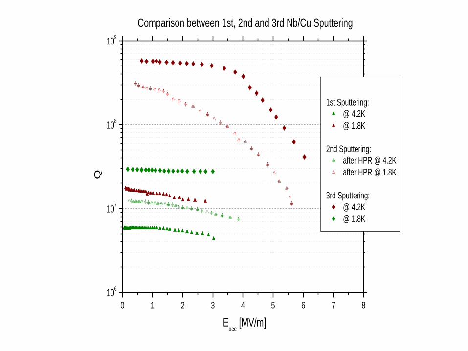
Comparison between 1st, 2nd and 3rd Nb/Cu Sputtering
1st Sputtering:
@ 4.2K
@ 1.8K
2nd Sputtering:
after HPR @ 4.2K
after HPR @ 1.8K
3rd Sputtering:
@ 4.2K
@ 1.8K
Q

0 1 2 3 4 5 6 7 8
106
107
108
109
Eacc
[MV/m]
Comparison between 1st, 2nd and 3rd Nb/Cu Sputtering
1st Sputtering:
@ 4.2K
@ 1.8K
2nd Sputtering:
after HPR @ 4.2K
after HPR @ 1.8K
3rd Sputtering:
@ 4.2K
@ 1.8K
Q

If we want to improve SRF
performances
we must study more deeply
Cryogenics
and precisely Heat Transfer
mechanism from a Surface to Liquid
Helium

If the adhesion of
Niobium to Copper is not
good, the cavity will go in
thermal runaway!!!!

Acknowledgements
• We thank F. Stivanello and V. Pastushenko for the Chemical and electrochemical polishing of the cavities,
• Serguey Stark for the huge work on RF,
• M. Martinello and M. Checchin for the sputtering and rf test