Embed Size (px)
Citation preview

Part 2: Piezoelectric Energy harvesting due to
harmonic excitations
Professor Sondipon Adhikari
FRAeS
Chair of Aerospace Enginering, College of Engineering, Swansea University, Swansea UKEmail: [email protected], Twitter: @ProfAdhikari
Web: http://engweb.swan.ac.uk/~adhikarisGoogle Scholar: http://scholar.google.co.uk/citations?user=tKM35S0AAAAJ
October 31, 2017
S. Adhikari (Swansea) GIAN 171003L27 Oct-Nov 17 — IIT-M 1 / 19

Outline of this talk
1 Introduction
2 The single-degree-of-freedom coupled model
3 Energy harvesters without an inductor
Time-domain and state-space equation
Response in the frequency domain
4 Energy harvesters with an inductor
Time-domain and state space equation
Response in the frequency domain
5 Summary
S. Adhikari (Swansea) GIAN 171003L27 Oct-Nov 17 — IIT-M 2 / 19
Introduction
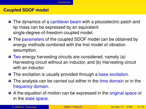
Coupled SDOF model
The dynamics of a cantilever beam with a piezoelectric patch and
tip mass can be expressed by an equivalent
single-degree-of-freedom coupled model.
The parameters of the coupled SDOF model can be obtained by
energy methods combined with the first model of vibration
assumption.
Two energy harvesting circuits are considered, namely (a)
Harvesting circuit without an inductor, and (b) Harvesting circuit
with an inductor
The excitation is usually provided through a base excitation.
The analysis can be carried out either in the time domain or in the
frequency domain.
A the equation of motion can be expressed in the original space or
in the state space.
S. Adhikari (Swansea) GIAN 171003L27 Oct-Nov 17 — IIT-M 3 / 19

The single-degree-of-freedom coupled model
Energy harvesting circuits
x tb( )PZT Layers
v t( )Rl
x t x tb( )+ ( )Tip Mass
(a) Harvesting circuit without an inductor
x tb( )PZT Layers
L v t( )Rl
x t x tb( )+ ( )Tip Mass
(b) Harvesting circuit with an inductor
Figure: Schematic diagrams of piezoelectric energy harvesters with two
different harvesting circuits.
S. Adhikari (Swansea) GIAN 171003L27 Oct-Nov 17 — IIT-M 4 / 19

Energy harvesters without an inductor
The equation of motion
The coupled electromechanical behaviour of the energy harvester
can be expressed by linear ordinary differential equations as
mx(t) + cx(t) + kx(t)− θv(t) = fb(t) (1)
Cpv(t) +1
Rlv(t) + θx(t) = 0 (2)
Here:
x(t): displacement of the mass
m: equivalent mass of the harvester
k : equivalent stiffness of the harvester
c: damping of the harvester
fb(t): base excitation force to the harvester
θ: electromechanical coupling
v(t): voltage
Rl : load resistance
Cp: capacitance of the piezoelectric layer
t : timeS. Adhikari (Swansea) GIAN 171003L27 Oct-Nov 17 — IIT-M 5 / 19

Energy harvesters without an inductor Time-domain and state-space equation
The state-space equation
The force due to base excitation is given by
fb(t) = −mxb(t) (3)
In the time domain, equations (1) and (2) can be expressed in the
state-space form as
dz1(t)
dt= A1z1(t) + B1fb(t) (4)
The state-vector z and corresponding coefficient matrices are
defined as
z1(t) =
x(t)x(t)v(t)
,A1 =
0 1 0
−k/m −c/m θ/m
0 −θ/Cp −1/(CpRl)
, (5)
and B1 =
0
1/m
0
(6)
S. Adhikari (Swansea) GIAN 171003L27 Oct-Nov 17 — IIT-M 6 / 19

Energy harvesters without an inductor Time-domain and state-space equation
The state-space equation
Equation (4) can be solved with suitable initial conditions and
elements of the state-vector can be obtained.
The solution will involve exponential of the matrix A1.
The natural frequencies of the system can be obtained by solving
the eigenvalue problem involving the matrix A1, that is, form the
roots of the following equation
det |A1 − λI3| = 0 (7)
Here I3 is a 3 × 3 identity matrix and the above equation will have
3 roots.
As the matrix A1 is real and the system is stable, two roots will be
in complex conjugate pairs and one root will be real and negative.
The interest of this paper is to analyse the nature of the voltage
v(t) when the forcing function is a harmonic excitation.
S. Adhikari (Swansea) GIAN 171003L27 Oct-Nov 17 — IIT-M 7 / 19
Energy harvesters without an inductor Response in the frequency domain
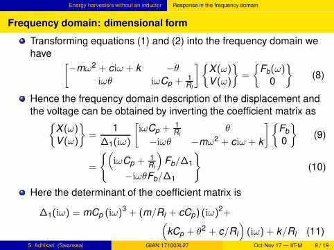
Frequency domain: dimensional form
Transforming equations (1) and (2) into the frequency domain we
have[
−mω2 + ciω + k −θ
iωθ iωCp + 1Rl
]
X (ω)V (ω)
=
Fb(ω)0
(8)
Hence the frequency domain description of the displacement and
the voltage can be obtained by inverting the coefficient matrix as
X (ω)V (ω)
=1
∆1(iω)
[
iωCp + 1Rl
θ
−iωθ −mω2 + ciω + k
]
Fb
0
(9)
=
(
iωCp + 1Rl
)
Fb/∆1
−iωθFb/∆1
(10)
Here the determinant of the coefficient matrix is
∆1(iω) = mCp (iω)3 + (m/Rl + cCp) (iω)
2+(
kCp + θ2 + c/Rl
)
(iω) + k/Rl (11)
S. Adhikari (Swansea) GIAN 171003L27 Oct-Nov 17 — IIT-M 8 / 19

Energy harvesters without an inductor Response in the frequency domain
Frequency domain: non-dimensional form
Transforming equations (1) and (2) into the frequency domain we
obtain and dividing the first equation by m and the second
equation by Cp we obtain
(
−ω2 + 2iωζωn + ω2n
)
X (ω)−θ
mV (ω) = Fb(ω) (12)
iωθ
CpX (ω) +
(
iω +1
CpRl
)
V (ω) = 0 (13)
Here X (ω), V (ω) and Fb(ω) are respectively the Fourier
transforms of x(t), v(t) and fb(t).
The natural frequency of the harvester, ωn, and the damping
factor, ζ, are defined as
ωn =
√
k
mand ζ =
c
2mωn(14)
S. Adhikari (Swansea) GIAN 171003L27 Oct-Nov 17 — IIT-M 9 / 19

Energy harvesters without an inductor Response in the frequency domain
Frequency domain: non-dimensional form
Dividing the preceding equations by ωn and writing in matrix form
one has[
(
1 − Ω2)
+ 2iΩζ − θk
iΩαθCp
(iΩα+ 1)
]
X
V
=
Fb
0
(15)
Here the dimensionless frequency and dimensionless time
constant are defined as
Ω =ω
ωnand α = ωnCpRl (16)
The constant α is the time constant of the first order electrical
system, non-dimensionalized using the natural frequency of the
mechanical system.
S. Adhikari (Swansea) GIAN 171003L27 Oct-Nov 17 — IIT-M 10 / 19

Energy harvesters without an inductor Response in the frequency domain
Frequency domain: non-dimensional form
Inverting the coefficient matrix, the displacement and voltage in
the frequency domain can be obtained as
X
V
=1
∆1
[
(iΩα+ 1) θk
−iΩαθCp
(
1 − Ω2)
+ 2iΩζ
]
Fb
0
=
(iΩα+ 1)Fb/∆1
−iΩαθCp
Fb/∆1
(17)
The determinant of the coefficient matrix is
∆1(iΩ) = (iΩ)3α+(2 ζ α+ 1) (iΩ)2+(
α+ κ2α+ 2 ζ)
(iΩ)+1 (18)
This is a cubic equation in iΩ leading to to three roots.
The non-dimensional electromechanical coupling coefficient is
κ2 =θ2
kCp(19)
S. Adhikari (Swansea) GIAN 171003L27 Oct-Nov 17 — IIT-M 11 / 19

Energy harvesters with an inductor
The equation of motion
The coupled electromechanical behaviour of the energy harvester
can be expressed by linear ordinary differential equations as
mx(t) + cx(t) + kx(t) − θv(t) = fb(t) (20)
Cpv(t) +1
Rlv(t) +
1
Lv(t) + θx(t) = 0 (21)
Here L is the inductance of the circuit. Note that the mechanical
equation is the same as given in equation (1).
Unlike the previous case, these equations represent two coupled
second-order equations and opposed one coupled second-order
and one first-order equations.
S. Adhikari (Swansea) GIAN 171003L27 Oct-Nov 17 — IIT-M 12 / 19

Energy harvesters with an inductor Time-domain and state space equation
The state-space equation
Equations (20) and (21) can be expressed in the state-space form
asdz2(t)
dt= A2z2(t) + B2fb(t) (22)
Here the state-vector z and corresponding coefficient matrices are
defined as
z2(t) =
x(t)x(t)v(t)v(t)
, B2 =
0
1/m
0
−θ/mCp
and (23)
A2 =
0 1 0 0
−k/m −c/m θ/m 0
0 0 0 1
θk/mCp θc/mCp θ2/mCp − 1/LCp −1/RCp
(24)
Equation (22) can be solved in a similar way as Equation (4).
S. Adhikari (Swansea) GIAN 171003L27 Oct-Nov 17 — IIT-M 13 / 19

Energy harvesters with an inductor Time-domain and state space equation
The state-space equation
Equation (22) can be solved with suitable initial conditions and
elements of the state-vector can be obtained.
The solution will involve exponential of the matrix A2.
The natural frequencies of the system can be obtained by solving
the eigenvalue problem involving the matrix A2, that is, form the
roots of the following equation
det |A2 − λI4| = 0 (25)
Here I4 is a 4 × 4 identity matrix and the above equation will have
4 roots.
As the matrix A2 is real and the system is stable, two roots will be
in complex conjugate pairs and the other two roots will be real and
negative.
S. Adhikari (Swansea) GIAN 171003L27 Oct-Nov 17 — IIT-M 14 / 19

Energy harvesters with an inductor Response in the frequency domain
Frequency domain: dimensional form
Transforming equation (21) into the frequency domain one obtains
− ω2θX (ω) +
(
−ω2Cp + iω1
Rl
+1
L
)
V (ω) = 0 (26)
Similar to equation (15), this equation can be written in matrix
form with the equation of motion of the mechanical system as
[
−mω2 + ciω + k −θ
−ω2θ −ω2Cp + iω 1Rl
+ 1L
]
X (ω)V (ω)
=
Fb(ω)0
(27)
S. Adhikari (Swansea) GIAN 171003L27 Oct-Nov 17 — IIT-M 15 / 19

Energy harvesters with an inductor Response in the frequency domain
Frequency domain: dimensional form
Inverting the coefficient matrix, the displacement and voltage in
the frequency domain can be obtained as
X (ω)V (ω)
=1
∆2
[
−ω2Cp + iω 1Rl
+ 1L θ
ω2θ −mω + ciω + k
]
Fb
0
=
(
−ω2Cp + iω 1Rl
+ 1L
)
Fb/∆2
ω2θFb/∆2
(28)
Here the determinant of the coefficient matrix is a fourth-order
polynomial in (iω) and is given by
∆2(iω) = mCp(iω)4 +
(cCpRlL + mL)
RlL(iω)3
+
(
mRl + cL + θ2RlL + kCpRlL)
RlL(iω)2 +
(cRl + kL)
RlL(iω) +
k
L(29)
S. Adhikari (Swansea) GIAN 171003L27 Oct-Nov 17 — IIT-M 16 / 19

Energy harvesters with an inductor Response in the frequency domain
Frequency domain: non-dimensional form
Transforming equation (21) into the frequency domain and dividing
by Cpω2n one has
− Ω2 θ
CpX +
(
−Ω2 + iΩ1
α+
1
β
)
V = 0 (30)
The second dimensionless constant is defined as
β = ω2nLCp (31)
This is the ratio of the mechanical to electrical natural frequencies.
Similar to Equation (15), this equation can be written in matrix
form with the equation of motion of the mechanical system (12) as[
(
1 − Ω2)
+ 2iΩζ − θk
−Ω2 αβθCp
α(
1 − βΩ2)
+ iΩβ
]
X
V
=
Fb
0
(32)
S. Adhikari (Swansea) GIAN 171003L27 Oct-Nov 17 — IIT-M 17 / 19
Energy harvesters with an inductor Response in the frequency domain
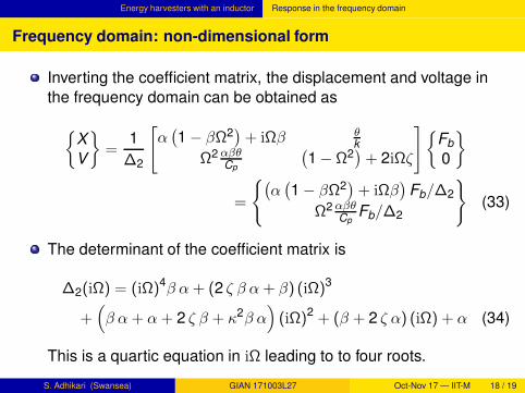
Frequency domain: non-dimensional form
Inverting the coefficient matrix, the displacement and voltage in
the frequency domain can be obtained as
X
V
=1
∆2
[
α(
1 − βΩ2)
+ iΩβ θk
Ω2 αβθCp
(
1 − Ω2)
+ 2iΩζ
]
Fb
0
=
(
α(
1 − βΩ2)
+ iΩβ)
Fb/∆2
Ω2 αβθCp
Fb/∆2
(33)
The determinant of the coefficient matrix is
∆2(iΩ) = (iΩ)4β α+ (2 ζ β α+ β) (iΩ)3
+(
β α+ α+ 2 ζ β + κ2β α)
(iΩ)2 + (β + 2 ζ α) (iΩ) + α (34)
This is a quartic equation in iΩ leading to to four roots.
S. Adhikari (Swansea) GIAN 171003L27 Oct-Nov 17 — IIT-M 18 / 19

Summary
Summary
The single-degree-of-freedom coupled model can effectively
represent a piezoelectric Euler-Bernoulli beam with a tip mass.
Dynamic analysis of the coupled SDOF is discussed in the time
domain and in the frequency domain.
Two circuit configurations have been introduced, namely, (a)
Energy harvesters without an inductor and (b) Energy harvesters
with an inductor
The first case leads to a state-space system of dimension three
and the model has three roots for it eigenvalues
The second case leads to a state-space system of dimension four
and the model has four roots for it eigenvalues
Explicit expressions of displacement and voltage response in the
frequency domain for both the cases have been derived in
closed-form.
S. Adhikari (Swansea) GIAN 171003L27 Oct-Nov 17 — IIT-M 19 / 19