Embed Size (px)
Citation preview

USA Ground Rods are the
second key to Lightning
Protection on Oilfield Sites
Underwriters Laboratories (UL) is notifying electricians, regulatory authorities and consumers
that certain ground rods sold at various hardware and home improvement stores bear a
counterfeit UL Mark for the United States.
http://www.rd.usda.gov/files/UEP_LoM_Supplement3_2015.pdf All rods used must be tested
based upon

Hazard: It is unknown if the mechanical properties and dimensional tolerances of the ground
rods are suitable to ensure an adequate ground path. The performance characteristics for
these ground rods are unknown.
Identification: The counterfeit ground rods are marked NEHRING NCC 588. The marking does
not include a UL control number or the word "LISTED".
What you should do: If you suspect a counterfeit ground rod was installed on your premises,
contact a qualified electrician and have it replaced with a UL-LISTED ground rod. If you have
one of these ground rods in your possession that has not been installed, UL recommends that
the counterfeit ground rod be returned to the place of purchase.
Distributed by: Unknown
Photos of the counterfeit ground rod: The counterfeit ground rods are marked with only the
following information:

This information supersedes UL’s previous public notice dated July 16, 2007.
Name of Product: Ground Rod, Catalog Number PWC 588
Units: Unknown quantity
Manufacturer: Unknown
Date of Manufacture: Unknown
Hazard: The products in question have not been evaluated for safety by UL and are not eligible
to bear the UL Mark. The thickness of the copper plating for these ground rods does not
comply with UL requirements. It is unknown whether the mechanical properties and
dimensional tolerances of the ground rods are suitable to ensure an adequate ground path.
Identification: The counterfeit ground rods are marked with the following information:
What You Should Do: If you suspect a counterfeit ground rod was installed on your premises,
contact a qualified electrician and have it replaced with a UL-Listed ground rod. If you have in
your possession a ground rod bearing a counterfeit UL Mark that has not been installed, UL
recommends that the counterfeit ground rod be returned to the place of purchase.
Distributed By: The ground rods are known to be sold at electrical distributors throughout the
United States.
Counterfeit Ground Rod: Photos of the counterfeit ground rods are shown below:

Legitimate Ground Rod: A photo of the legitimate ground rod is shown below:

Consider the inspector who passes a grounding installation in which an unlisted, unmarked
ground rod is used. He can’t know if the rod is the required eight feet in length or if it has the
required coating thickness. Unless he is carrying a micrometer, he can’t really know whether
the rod is the proper diameter. Should an electrical fire be the result of improper grounding,
he could be liable for damages. If there is a death or a serious injury involved, the damages
could be staggering.
By demanding the use of clearly marked listed (UL or CSA) ground rods, the inspector avoids
this potential liability. Listed rods meet all requirements of the code.
Wholesalers also have significant liabilities associated with selling unmarked rods. While most
galvanized and stainless steel ground rods sold today are not marked, if a rod that has no
markings – neither a listing mark nor a manufacturer’s name or symbol – fails to pass
inspection, the installer could demand a refund from the wholesaler. If there is no way to
identify the manufacturer, the wholesaler is stuck with the loss. By the same token, if there is
a fire or electrocution associated with that same rod, with no traceable manufacturer’s
marking, the liability could stop at the wholesaler.
Selling only rods that are clearly marked with the manufacturer’s name or symbol provides
some protection for the wholesaler against this kind of potential product liability.
An unmarked rod protects only the manufacturer. If you’ve ever wondered why every ground
rod isn’t marked, now you know one big reason.
A contractor’s liability is often limited to a year and a day after a job is completed and passes
inspection. Still, it is hard to imagine why anyone would accept 365 days of potentially
catastrophic liability to save a few cents on a ground rod.
Those most at risk are consumers: homeowners and business owners who could literally lose
everything. They play no role in choosing ground rods, but the lives of their families and
companies are in the hands of those who do. Maybe it is just a ground rod to you, but to them
it could be a matter of life and death. Make the responsible choice. Installing and selling only
traceable, listed ground rods is in everybody’s best interest.

A national standard to improve product quality as well as dimensional and physical
characteristics for users of galvanized ground rods, the National Electrical Manufacturers
Association (NEMA), Rosslyn, Va., recently released ANSI/NEMA GR 1-2001, Grounding Rod
Electrodes and Ground Rod Electrode Couplings.
The ANSI-approved standard, which replaces NEMA GR 1-1997, provides information
concerning the construction, testing, performance, and manufacture of ground rod electrodes
and ground rod electrode couplings. It includes information about materials, construction, and
performance of copper bonded, hot-dip galvanized ground rod electrodes. http://www.neca-
neis.org/
Testing.
The standard three-point fall-of-potential or slope test on a “totally isolated electrode,” as
described in the IEEE Std. 81-1983, will determine the effectiveness of a grounding system.
You can test nearly any site with a standard three-point ground tester. This equipment works
at a safe output of up to 50 mA and — when not affected by on-site stray voltages — provides
accurate values if properly employed. However, people often perform the test without shutting
down power or isolating the grounding system from the utility neutral. Such a mistake will only
provide you with a test of the utility neutral ground.
What Are Ground Rods?
Ground rods are used to connect the grounding system of electrical systems to earth ground.
Ground rods are manufactured of many different materials, although the two most popular are
probably made of copper clad or galvanized steel. These materials are very good conductors
of electricity and allow any dangerous electricty to flow to ground, taking the danger away
from you and the electrical panel.
Ground rods come in both 8' and 10' lengths, however, an 8' ground rod is the common size
used in residential installations. As a rule, ground rods must be a minimum of 8' long, so do
not cut them off! If you are in very dry ground, you may want to consider a special clamp that
allows you to stack ground rods.
Another option is to add a second ground rod, which is a better option, but remember that the
NEC requires them to be a minimum of 6' apart. If possible, try to get the ground rods in a
moist area around your home. Usually, the area close to the exterior wall has enough moisture
due to runoff water from downspouts.
Ground rods come in varying thickness that include 3/8", 1/2", 3/4", and 1". The minimum
diameter ground rod allowed is 3/8".
Although there are many types of wire, including copper and aluminum, copper is the best for
connecting to earth ground. You see, the ground wire, often referred to as the grounding
electrode conductor, is the link between the ground rod and the service ground connection.
Usually a #6 wire is used to make this connection, but a larger wire may be used to make a
bigger connection if you'd like. In larger electrical service installations, a larger ground wire
would be needed.
Grounding clamps are used to connect the grounding electrode conductor to the ground rod.
There are mechanical clamps that have set screws taht tighten the clamp around the ground
rod to form a connection.

An acorn clamp is an oval-shaped clamp with a bolt used to tighten it to the ground rod. An
acorn clamp is the most commonly used clamp for ground rod connections and is approved for
direct burial applications. The grounding conductor should be attached against the ground rod
and in the "v" of the acorn clamp, opposite the bolt side of the clamp.
Driven Rod
The standard driven rod or copper-clad rod consists of an 8 to 10 foot length of steel with a 5
to 10-mil coating of copper. This is by far the most common grounding device used in the field
today. The driven rod has been in use since the earliest days of electricity with a history
dating as far back as Benjamin Franklin.
Driven rods are relatively inexpensive to purchase, however ease of installation is dependent
upon the type of soil and terrain where the rod is to be installed. The steel used in the
manufacture of a standard driven rod tends to be relatively soft. Mushrooming can occur on
both the tip of the rod, as it encounters rocks on its way down, and the end where force is
being applied to drive the rod through the earth. Driving these rods can be extremely labor-
intensive when rocky terrain creates problems as the tips of the rods continue to mushroom.
Often, these rods will hit a rock and actually turn back around on themselves and pop back up
a few feet away from the installation point.
Because driven rods range in length from 8 to 10 feet, a ladder is often required to reach the
top of the rod, which can become a safety issue. Many falls have resulted from personnel
trying to literally ‘whack’ these rods into the earth, while hanging from a ladder, many feet in
the air.

The National Electric Code (NEC) requires that driven rods be a minimum of 8 feet in length
and that 8 feet of length must be in direct contact with the soil. Typically, a shovel is used to
dig down into the ground 18 inches before a driven rod is installed. The most common rods
used by commercial and industrial contractors are 10 ft in length. Many industrial
specifications require this length as a minimum.
A common misconception is that the copper coating on a standard driven rod has been applied
for electrical reasons. While copper is certainly a conductive material, its real purpose on the
rod is to provide corrosion protection for the steel underneath. Many corrosion problems can
occur because copper is not always the best choice in corrosion protection. It should be noted
that galvanized driven rods have been developed to address the corrosion concerns that
copper presents, and in many cases are a better choice for prolonging the life of the grounding
rod and grounding systems. Generally speaking, galvanized rods are a better choice in all but
high salt environments.
An additional drawback of the copper-clad driven rod is that copper and steel are two
dissimilar metals. When an electrical current is imposed, electrolysis will occur. Additionally,
the act of driving the rod into the soil can damage the copper cladding, allowing corrosive
elements in the soil to attack the bared steel and further decrease the life expectancy of the
rod. Environment, aging, temperature and moisture also easily affect driven rods, giving them
a typical life expectancy of five to 15 years in good soil conditions. Driven rods also have a
very small surface area, which is not always conducive to good contact with the soil. This is
especially true in rocky soils, in which the rod will only make contact on the edges of the
surrounding rock.
A good example of this is to imagine a driven rod surrounded by large marbles. Actual contact
between the marbles and the driven rod will be very small. Because of this small surface
contact with the surrounding soil, the rod will increase in resistance-to-ground, lowering the
conductance, and limiting its ability to handle high-current faults.
Advanced Driven Rods
Advanced Driven Rods are specially engineered variations of the standard driven rod, with
several key improvements. Because they present lower physical resistance, advanced rods
can now go into terrain where only large drill-rigs could install before and can quickly be
installed in less demanding environments. The modular design of these rods can reduce
safety-related accidents during installation. Larger surface areas can improve electrical
conductance between the soil and the electrode.

Of particular interest is that Advanced Driven Rods can easily be installed to depths of 20 ft or
more, depending upon soil conditions.
Advanced Driven Rods are typically driven into the ground with a standard drill hammer. This
automation dramatically reduces the time required for installation. The tip of an Advanced
Driven Rod is typically made of carbide and works in a similar manner to a masonry drill bit,
allowing the rod to bore through rock with relative ease. Advanced Driven Rods are modular in
nature and are designed in five foot lengths. They have permanent and irreversible
connections that enable an operator to install them safely, while standing on the ground.
Typically, a shovel is used to dig down into the ground 18 inches before the Advanced Driven
Rod is installed. The Advanced Driven Rod falls into the same category as a driven rod and
satisfies the same codes and regulations.
In the extreme northern and southern climates of the planet, frost-heave is a major concern.
As frost sets in every winter, unsecured objects buried in the earth tend to be pushed up and
out of the ground. Driven grounding rods are particularly susceptible. Anchor plates are
sometimes welded to the bottom of the rods to prevent them from being pushed up and out of
the earth by frost-heave. This however requires that a hole be augured into the earth in order
to get the anchor plate into the ground, which can dramatically increase installation costs.
Advanced Driven Rods do not suffer from frost-heave issues and can be installed easily in
extreme climes.
Grounding Plates
Grounding plates are typically thin copper plates buried in direct contact with the earth. The
National Electric Code requires that ground plates have at least 2 ft2 of surface area exposed
to the surrounding soil. Ferrous materials must be at least .20 inches thick, while non-ferrous
materials (copper) need only be .060 inches thick. Grounding plates are typically placed under
poles or supplementing counterpoises.

As shown, grounding plates should be buried at least 30 inches below grade level. While the
surface area of grounding plates is greatly increased over that of a driven rod, the zone of
influence is relatively small as shown in “B”. The zone of influence of a grounding plate can be
as small as 17 inches. This ultra-small zone of influence typically causes grounding plates to
have a higher resistance reading than other electrodes of similar mass. Similar environmental
conditions that lead to the failure of the driven rod also plague the grounding plate, such as
corrosion, aging, temperature, and moisture.
Ufer Ground or Concrete Encased Electrodes
Originally, Ufer grounds were copper electrodes encased in the concrete surrounding
ammunition bunkers. In today’s terminology, Ufer grounds consist of any concrete-encased
electrode, such as the rebar in a building foundation, when used for grounding, or a wire or
wire mesh in concrete.
Concrete Encased Electrode
The National Electric Code requires that Concrete Encased Electrodes use a minimum No. 4
AWG copper wire at least 20 feet in length and encased in at least 2 inches of concrete. The
advantages of concrete encased electrodes are that they dramatically increase the surface
area and degree of contact with the surrounding soil. However, the zone of influence is not
increased, therefore the resistance to ground is typically only slightly lower than the wire
would be without the concrete.

Concrete encased electrodes also have some significant disadvantages. When an electrical
fault occurs, the electric current must flow through the concrete into the earth. Concrete, by
nature retains a lot of water, which rises in temperature as the electricity flows through the
concrete. If the extent of the electrode is not sufficiently great for the total current flowing,
the boiling point of the water may be reached, resulting in an explosive conversion of water
into steam. Many concrete encased electrodes have been destroyed after receiving relatively
small electrical faults. Once the concrete cracks apart and falls away from the conductor, the
concrete pieces act as a shield preventing the copper wire from contacting the surrounding
soil, resulting in a dramatic increase in the resistance-to-ground of the electrode.
There are many new products available on the market designed to improve concrete encased
electrodes. The most common are modified concrete products that incorporate conductive
materials into the cement mix, usually carbon. The advantage of these products is that they
are fairly effective in reducing the resistivity of the concrete, thus lowering the resistance-to-
ground of the electrode encased. The most significant improvement of these new products is
in reducing heat buildup in the concrete during fault conditions, which can lower the chances
that steam will destroy the concrete encased electrode. However some disadvantages are
still evident. Again, these products do not increase the zone-of-influence and as such the
resistance-to-ground of the concrete encased electrode is only slightly better than what a
bare copper wire or driven rod would be in the ground. Also a primary concern regarding
enhanced grounding concretes is the use of carbon in the mix. Carbon and copper are of
different nobilities and will sacrificially corrode each other over time. Many of these products
claim to have buffer materials designed to reduce the accelerated corrosion of the copper
caused by the addition of carbon into the mix. However, few independent long-term studies
are being conducted to test these claims.
Electrolytic Electrode
The electrolytic electrode was specifically engineered to eliminate the drawbacks of other
grounding electrodes. This active grounding electrode consists of a hollow copper shaft filled
with natural earth salts and desiccants whose hygroscopic nature draws moisture from the
air. The moisture mixes with the salts to form an electrolytic solution that continuously seeps
into the surrounding backfill material, keeping it moist and high in ionic content.
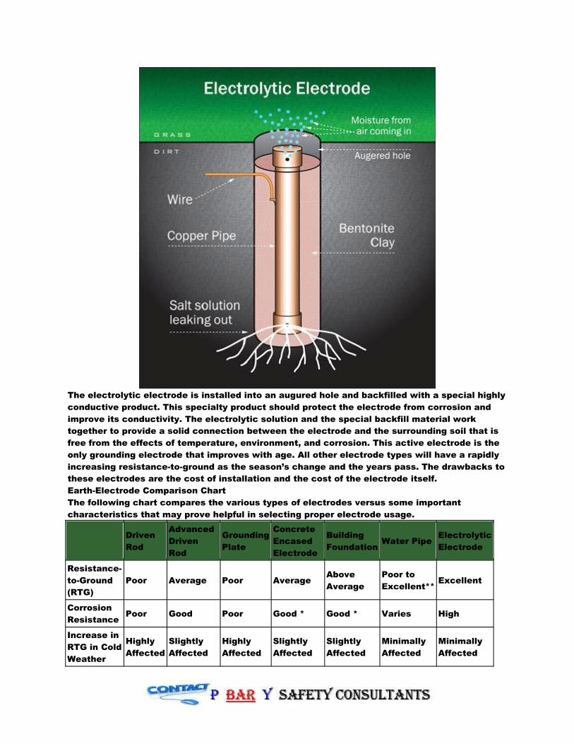
The electrolytic electrode is installed into an augured hole and backfilled with a special highly
conductive product. This specialty product should protect the electrode from corrosion and
improve its conductivity. The electrolytic solution and the special backfill material work
together to provide a solid connection between the electrode and the surrounding soil that is
free from the effects of temperature, environment, and corrosion. This active electrode is the
only grounding electrode that improves with age. All other electrode types will have a rapidly
increasing resistance-to-ground as the season’s change and the years pass. The drawbacks to
these electrodes are the cost of installation and the cost of the electrode itself.
Earth-Electrode Comparison Chart
The following chart compares the various types of electrodes versus some important
characteristics that may prove helpful in selecting proper electrode usage.
Driven
Rod
Advanced
Driven
Rod
Grounding
Plate
Concrete
Encased
Electrode
Building
Foundation Water Pipe
Electrolytic
Electrode
Resistance-
to-Ground
(RTG)
Poor Average Poor Average Above
Average
Poor to
Excellent** Excellent
Corrosion
Resistance Poor Good Poor Good * Good * Varies High
Increase in
RTG in Cold
Weather
Highly
Affected
Slightly
Affected
Highly
Affected
Slightly
Affected
Slightly
Affected
Minimally
Affected
Minimally
Affected

Increase in
RTG over
Time
RTG
Worsens
RTG
typically
unaffected
RTG
Increases
RTG
typically
unaffected
RTG
typically
unaffected
RTG
typically
unaffected
RTG
Improves
Electrode
Ampacity Poor Average Average Average *
Above
Average *
Poor to
Excellent** Excellent
Installation
Cost Average Excellent
Below
Average
Below
Average Average Average Poor
Life
Expectancy
Poor
5–10
years
Average
15–20
years
Poor
5-10
years
Average *
15-20
years
Above
Average *
20-30
years
Below
Average*
10-15
years
Excellent
30-50 years
* High-current discharges can damage foundations when water in the concrete is rapidly
converted into steam.
** When part of extensive, bare, metallic, electrically continuous water system.
USA Codes and Enforcement
This publication covers state safety requirements for electrical construction. Most states
adopt by reference the National Electrical Code (ANSI/NFPA standard 70), sometimes with
local changes. Some also adopt by reference the National Electrical Safety Code (ANSI/IEEE
standard C2). Many states with statewide electrical codes allow local jurisdictions to adopt
more stringent requirements. Some states have no electrical codes or enforcement authority,
leaving these matters entirely to local jurisdictions.
Contractor/Electrician Licensing
States with statewide licensing requirements generally have an electrical or licensing Board
with the power to give examinations and issue licenses, and to suspend and revoke licenses
for cause. Some states have no statewide licensing requirements, leaving this matter entirely
to local jurisdictions. Some states have reciprocity arrangements for contractor/electrician
licensing with others that have the same or similar requirements. These are generally
neighboring states.
Exceptions: Some states exempt certain types of work or classes of installations from
electrical code, inspection, and/or licensing requirements. Typical exemptions are listed
below; they are referenced by code letter in the individual state listings:
1.Electric utility installations and wiring, up to and including meters on customer premises.
2.Communications systems including radio, cable television, telecommunications, and similar
systems.
3.Industrial installations.
4.Installations of a specialized nature such as mines, refineries, gas and oil fields, and
transportation systems.
Considerations for Grounding Grid Effectiveness
Use wire at least as large as specified in NEC table 250.94.
Before energizing, perform a continuity test between the grid and the neutral ground
connection.
The ground grid wire must be mechanically continuous to the neutral ground bus.
The ground grid connection may not have any sharp bends in it.

Texas
Code
The 2008 NEC (implemented September 1st, 2008) will be the effective "minimum standard"
for all electrical installations in Texas that is covered by the Act. In addition, all examinations
for state electrical licenses offered on or after that date will be based on the 2008 NEC.
Enforcement
Contractors must have a Texas State Electrical License to perform electrical installations.
Texas Department of Licensing and Regulations - Fort Worth
1501 Circle Drive, Suite 215
Ft. Worth, TX 76119
(817) 321-8350
(817) 321-8365 fax
Texas Department of Licensing and Regulations - Houston
5425 Polk Avenue, Suite G40
Houston, TX 77023
(713) 924-6300
(713) 921-3106 fax
www.tdlr.state.tx.us
You will need one auxiliary potential probe (P2) and one auxiliary current probe (C2) to
perform a three-point test. Connect the C1 and P1 either directly or internally through the
meter to the electrode under test. To perform a valid test, place the C2 probe 100 ft from the
potential probe. If the system under test is larger than one or two 10-ft electrodes, you must
determine the width and length of the system as well as the diagonal dimension. Place the C2
probe at least three times the length of the diagonal from the system under test. For example,
if the system is 30 ft by 40 ft, the diagonal will be 50 ft. You should place the C2 probe a
minimum of 150 ft (3 ft × 50 ft) from the system under test. If the P2 values remain within 5%
to 10% of each other at 52% (52 ft), 62%
(62 ft) and 72% (72 ft) distances, you can
assume the results are accurate. Use the
62% reading as your base value.
To get an accurate test, place the
auxiliary probes on opposite sides of the
electrode under test and take the
average of the readings. If the test values
differ greatly, rotate the position of the
probes 90° around the electrode and take
two more tests. Now average the four
results. Keep in mind, dry conditions or highly resistant soils can make it difficult to get
consistent readings. Adding salted water around the test probes or employing deeper test
probes may be necessary. If stray voltages affect your readings, running a test 90° from the
first test should cancel out these objectionable currents. It may be necessary to use a tester
that provides adjustable or variable test currents.

An alternative to this kind of testing is the clamp-on ground tester, which is effective in many
grounding situations and doesn't require you to turn off the power — nor does its effectiveness
depend on how well you lay out your probes. However, the instrument is useful only if you
follow the instructions that come with the
tester. Doing so will yield a valid test or
will render an indication the test is invalid
— usually, a reading of 0.7 ohms.
When used properly, the clamp-on gives
consistent readings and is an excellent
tool for periodic checking of an existing
system against baseline readings. If you
are reading anything less than a few ohms,
you're probably reading a ground loop. In
that case, you need to look at the system
and make sure you're at the right point.
Don't overlook the three-point test during
new construction either — you may never
get another opportunity to conduct that particular test.
The National Electrical Code requirement in Sec. 250-54, which requires the resistance to
ground of a single-made electrode (e.g., ground rod) to be 25 ohms or less. Unfortunately, it
seems many electrical professionals don't actually test the grounding electrode system (GES)
to ensure they're meeting this requirement. Even fewer of you feel testing the earth ground
system is worthwhile. From a power quality perspective, you may be right.
A GES provides:
• A zero-volt reference for the supplied or derived power systems.
• A path to dissipate lightning or fault current (for higher voltage systems).
• A path for the dissipation of electrostatic currents.
A GES consists of two components: the grounding electrode conductor (GEC) and the
grounding electrode.
You can choose a bare or insulated GEC (sized per Table 250-66) in copper or aluminum. The
GEC connects the grounding electrode to the grounded circuit conductor, the equipment-
grounding conductor, or both, at the main service equipment or the source of a separately
derived system.
The most common types of grounding electrodes (identified by Sec. 250-50 and 250-52) are:
• Structural steel
• Metal underground water pipe
• Ground ring
• Ground rods
How to test. You should measure the resistance of an electrode with respect to the
surrounding soil in the area. You can only do this by using the fall-of-potential method with a
three-terminal, earth ground resistance tester. To properly test the resistance of a GES, you
must follow some simple rules:
1. Disconnect the electrode under test from the rest of the electrical system. Considering this,
it is not possible to test the grounding electrode system in nearly all circumstances.
2. Don't use a meter that injects DC current into the ground rod. Do not use standard VOMs.
3. Don't perform test measurements if the current on a GES is greater than 5A.
Contrary to popular belief, clamp-on earth ground resistance testers can be inaccurate in field
applications. These testers require a low-resistance feedback loop with adequate spacing
between electrode systems to provide meaningful readings. Many people often add a high
resistance (caused by loose connections in the feedback loop) to the displayed value of the

meter. Also, inadequate spacing between electrodes results in the meter only making a
comparative bonding test, which almost always results in a low-resistance value.
Why do I need to reach 25 ohms? The most credible answer to this question is: 25 ohms is a
reasonable value to strive for, given the average soil resistivity for most regions of the United
States. Keep in mind, however, that 25 ohms is not a requirement when you install multiple
electrodes. This is only a requirement for single-made electrodes, per Sec. 250-56. If you drive
the first rod and get a resistance reading greater than 25 ohms, the NEC allows you to drive an
additional rod 6 ft away from the first rod.
Let's say, for example, you drive a ground rod into the soil, but instead of testing that rod to
see if it meets the 25-ohm criteria you drive the second. Once the two rods bond together,
consider the GES complete. But if you don't take a measurement, how do you know your
installation meets Code?
Reality check. In most commercial and industrial low-voltage power systems, technicians do
not perform earth ground resistance testing. But this shouldn't surprise you. An informal poll
of 50 electricians found only four performed earth ground testing in the past. The reasons
cited for not testing were:
• The testers were too expensive.
• The test was too confusing and took too much time.
• Two rods are good enough (most common response).
Impact of power quality. Believe it or not, nearly all electronic equipment will operate properly
without the benefit of a low-resistance GES. Power quality site surveys have shown that in
situations where the grounding electrode resistance is between 5 ohms and 105 ohms, it
doesn't affect equipment.
Galvanized ground rods
The NEC establishes the minimum requirements considered necessary for safety. Most
industrial installations go over and above what the Code requires, since performance and
safety is usually more important than the overall costs.
While process units typically don’t have a complete copper grid like that installed at high-
voltage substations (see IEEE Std. 80), they are concerned about touch and step potentials
during large faults or lightning strikes. Also, during maintenance inspections, the inspector
can visually see that each piece of equipment has a grounding conductor attached to it and
doesn’t have to be concerned if the equipment is adequately grounded. Each tap to equipment
above ground can also be used to test the grounding system to ensure it is intact and
functional.
Copper plating is corrosion resistance. Copper, silver, mercury and gold have high resistance
to corrosion, while processed metals like aluminum and magnesium are easily corroded. Noble
metals like copper become the cathode when joined together with less noble metals in the
presence of an electrolyte (water). Less noble metals become the sacrificial anode and
corrode away.
Not listed in the galvanic table of metals is Graphite, since it is not a metal. Graphite is even
more noble than silver and certainly much nobler than copper. Therefore, if a graphite backfill
material is to be used as a ground “enhancer” to surround copper, the copper will be
sacrificial to the graphite and will dissolve away into the soil.
The following affect the amount and speed of corrosion both above and below the soil:
1. Water. The presence of water mixed with contaminants is the basis of galvanic
corrosion. Pure rain water is slightly acidic (pH 5.5 to 6.0). It picks up carbon dioxide
as it falls which creates carbonic acid. It can start attacking some metals, even
copper, without being in a junction. The ions etched from the copper go into solution in
the rain water. As this rain water drips on galvanized tower sections, it will cause the
zinc to combine and wash off. This leaves the bare steel to oxidize away.
2. Oxygen. This is the main corrosion accelerator. Rain water also picks up oxygen as it
falls through the atmosphere. Water provides an excellent carrier of oxygen.
3. Temperature. Generally, the higher the temperature the faster the chemical reaction.
4. Texture of the metal(s). Glass smooth surfaces are less likely to corrode than rough
finishes.
5. Hydrogen Sulfide. A gaseous product of exhaust emissions, it combines with rain water
creating acid rain. Chlorine. Tap water can have an acidic effect on underground
materials.
6. Inert gases. Helium displaces oxygen and reduces the corrosive effect.
7. Alkaline. Although some alkalis tend to increase the rate of carbon dioxide absorption
from the air, which creates corrosive carbonate solutions, slight amounts of alkalinity
can reduce corrosion rates.
8. Salts. Sodium chloride, found just about everywhere, increases the soil conductivity
and also Why Steel Ground Rods are Copper Plated Document ID: PEN1008
9. Salts. Sodium chloride, found just about everywhere, increases the soil conductivity
and also increases the corrosion process in nearly the same proportion to its
concentration. Other naturally occurring salts or non natural added salts do the same.
Only sodium carbonate or phosphate and potassium ferricyanide form a protective film
that prevents further corrosion.
10. Microorganisms. Both bacteria and fungus can deteriorate metal. Some will give off
acids in trapped water or when they die and decompose into acids.
Types of Corrosion
There are several types of corrosion. Listed below are the common names given for
descriptive purposes:
1. Uniform Etch: A direct chemical attack from salts, urine and acids. If allowed to
continue, a polished surface will dull and then take on a rough or frosted appearance.
2. Pitting: Tiny pin holes from localized chemical or galvanic attack.
3. Inter-granular: Usually galvanic, this is a selective attack along the grain boundaries of
an alloy metal. We have referenced this as “de-alloying.” Typical corrosion-resistant
alloys can break down when corrosion actually works on the individual components of
the alloy.
4. Exfoliation: Found on extruded metals, the corrosion occurs just below the metal
surface and causes a blister to form. This appears where the extruding dyes have
forced the crystal structure of the metal to change direction.
5. Galvanic: The classic two dissimilar metal connection with a water electrolyte bridge
is the most basic of corrosion problems.
6. Concentration Cell: As the amount of oxygen reaching the electrolyte varies, the rate
of corrosion will vary accordingly. High concentrated areas of oxygen will have high
levels of corrosion.
7. Stress: More corrosion will occur where high tensile stress is applied. This is where
metal is bent or where rivets have been driven. Metals that have been cold worked
(bent back and forth several times) should be annealed (stress relieved by heating).
Stress corrosion appears as a crack running parallel to the metal grain.
8. Fatigue: Another form of stress corrosion where pits are defined along the grain.
Additional stress begins to concentrate around them and cracking occurs at the
bottom of the pits.
9. Filiform: Thread-like filament corrosion occurring under painted surfaces where water
and oxygen have penetrated and form a corrosion concentration cell. Why Steel Ground
Rods are Copper Plated.
Helpful Hints
• Mother Nature will see that nothing we place in the soil will last forever. But we can do
our part to design a grounding system that lasts.
• Use all similar metals in your grounding system. If copper is used, don’t mix in tin
plated copper wire.
• On mechanical compression joints, copper joint compound should be used to cover the
hardware. This will prevent corrosion that can cause a loss of compression strength
and increase joint resistance over time. The joint compound, a petroleum based
product with conductive copper flakes, displaces water, oxygen, acids and salts.
• Exothermic connections should be allowed to cool slowly to prevent stress corrosion.
• A grounding system should be tested annually.
• Grounding systems should also be checked annually for corrosion.
• Know your soil’s pH. If acidic, either correct it to neutral or suffer the consequences.
There is one caveat though. When installing large amounts of copper in contact with the earth,
a cathodic protection study should be performed. Copper will act as a cathode and any anodic
material in the earth in the vicinity of the copper, such as iron or steel, will sacrifice itself to
the copper because a corrosion cell could be formed. Underground piping/rebar may need to
have a cathodic protection system installed to protect it from the copper.
The NEC code specifies that a solid copper wire used to connect to a ground rod must be #6
gauge, or larger. It doesn't specify a limit as to the maximum length. Of course, shorter is
better.
The grounding system serves a few different purposes:
1. Make the voltage of the land around your business be at approximately the same voltage
as your power line neutral. This means that you can't shock yourself by holding an
appliance in one hand and touching the earth with your feet.
2. A fault path during lightning storms. When lightning strikes near your business, it
energizes your electrical lines. Surge suppressors will try to shunt the voltage to the
neutral or ground line. Having a good ground will maximize the power transfer out of your
business.
3. Safety. If the neutral going to your business is disconnected and you don't have a ground
to neutral bond in your main panel, both prongs of each electric outlet in your business
will have the full line voltage on it. Older appliances will connect their chassis to neutral,
causing their chassis to hold 120V. With the grounding system properly connected, the
ground will pull the neutral closer to 0 V, reducing the risk of shock.
So, what resistance to ground should you want? The smaller, the better. The electrical code
states that with one ground rod, it must have a maximum resistance of 25 ohms to the earth.
According to a Fluke brochure, you should try to have a ground to earth resistance of less than
25 ohms, or less than 5 ohms for sensitive electrical equipment.
#6 gauge solid copper is approx 0.4 ohm/thousand feet, so having a run of thirty feet will add
minimal extra resistance (about 0.008 ohm). But, it will somewhat reduce the effectiveness of
your system during a lightning storm. For the best lightning protection, your grounding wires
should not have any sharp bends. This is because lightning is a very high frequency signal, and
the wire's impedance increases with frequency. The 0.4 ohm/thousand feet figure is only valid
at DC (zero frequency). While sharp bends do not increase the DC resistance, it does increase
the high frequency impedance.
There are many other rules that I have not mentioned (read the NEC book (NFPA 70) or your
local code for details). As always, use caution when working around electrical systems.
Recently, UL-listed galvanized ground rods have shown up in the market. You may have
wondered why now and what does this mean? Underwriters Laboratories had never listed
galvanized ground rods in the past and there are no listing requirements for galvanized rods in
the existing UL 467 Standard, unlike copper-bonded and stainless steel rods which have clear
listing requirements. These rods use the higher tensile strength steel found in copper-bonded
rods, which is a plus, but we’ve already established that as a minor benefit. These galvanized
rods have a smaller diameter than non-UL listed galvanized rods requiring special accessories
and different exothermic welding equipment.
One of the industries leaders Mr. Johnson noted
A lightning strike to an unprotected structure can be catastrophic. One bolt can pack up to
100 million volts of electricity. Imagine that kind of current traveling through business
circuitry. The National Lightning Safety Institute estimates there are roughly 15 to 20 million
ground strikes per year with a higher ratio in areas where soil resistivity is greater.
A path of least resistance
Damage from lightning strikes to residences and businesses can be reduced with the
installation of a lightning protection system. Systems are designed to control or provide a
designated path for the lightning current to travel to ground, with the purpose of minimizing
the risk of fire or explosion within nonconductive parts of the structure.
Most lightning protection systems are made up of several components, including air terminals
(lightning rods), conductors, and surge arrestors and suppressors. Regardless of the type of

system, all must link to some type of ground terminals, usually in the form of metal rods driven
into the earth.
While grounding is not exclusively intended to prevent lightning damage, it can help ensure
electrical safety with its ability to provide reliable electrical connection to the earth. Homes
that meet the current National Electrical Code (NEC) typically have a grounding-electrode
system connected to their electrical service, and these homes are typically equipped with an
electrical distribution system, which includes grounded outlets.
Commercially, good grounding is essential for the power quality of electrical equipment and
distribution systems. The IEEE Emerald Book provides additional guidelines for grounding
electronic and electrical equipment. Some utility companies develop substation grounding
grids to provide electrical protection for items such as power transformers.
Equal ground
Grounding rods can vary from sophisticated electrolytic rod systems with active soil moisture
replenishment to metal-coated steel rods. In addition to the copper-clad and stainless-steel
ground-rod electrodes currently offered within the metal-coated steel-rod category, the
industry has a relatively new alternative with UL-listed hot-dip galvanized (zinc-coated)
ground-rod electrodes.
According to David Prior, technical services manager at Galvan Industries-which
manufactures all three types of metal-coated rods-Underwriters Laboratories has listed the
hot dip galvanized ground rod electrode to UL 467, ensuring the same critical criteria is
mandated for the galvanized rods as the copper-coated rods currently listed.
“Since the 5/8-inch nominal diameter copper-clad and hot-dip galvanized rods are produced
fundamentally from the same steel core, the only difference is the coating,” said Prior. “The
intention of UL 467 is to provide conformity testing of the rod throughout the industry.”
Before the introduction of the listed galvanized ground rod, most manufacturers produced the
ground rods to an ANSI C135.30 specification, which expired in 1993 and did not meet the
NEC. The listed galvanized ground rod, Prior said, meets the strictest interpretation of the
NEC.
All rod-type grounding electrodes or “ground rods” are manufactured from a steel core with a
nonferrous coating to guard the steel. To protect the industry against poor-quality steel,
Galvan and other NEMA members developed the ANSI-approved NEMA GR-1 in 2001 ground-rod
specification, which established minimum acceptable performance criteria.

Eliminating coating controversy
Electrical codes allow users to specify either bare or coated grounding electrodes. UL-
approved coatings include copper, zinc or stainless steel. Galvanized rods have a zinc coating
thickness of 3.9 mils (.0039 in. or 710 g/m2) and copper rods are coated to a thickness of 10
mils or 0.01 in.
Technical information indicates that hot-dip galvanized coatings are formed through a
diffusion reaction between iron and zinc resulting in a metallurgical bond of the two metals.
Copper is electrodeposited as a pure copper coating bonded to the steel's surface.
Within the industry a difference of opinion stems from a belief that copper cladding is superior
because its thicker coating offers better conductivity of fault than zinc and provides longer
life due to better corrosion resistance. The difference in conductivity between copper and zinc
coatings is statistically insignificant, according to IEEE-80, said Prior. Either coating is
capable of safely conducting fault to ground.
“With regards to life expectancy, state departments of transportation have used buried
galvanized steel culvert bridges for decades. If galvanized steel could only be expected to last
15 years, our transportation system along secondary roads would have been closed to traffic
permanently long ago,” Prior said.
According to the National Association of Corrosion Engineers, the galvanic or electromotive
force (EMF) scale of metals illustrates in ascending order the more-noble metals to less-noble
metals. Copper is more noble than steel and zinc.
“Less-noble metals are sacrificial to more-noble metals when they are connected in a
corrosion cell. That means a steel core will sacrifice itself to protect the copper coating if it's
damaged while being driven into the soil. Zinc is less noble or anodic and will sacrifice itself
preferentially to protect the steel core if the coating is damaged,” Prior said.
Prior pointed out that neither galvanizing nor copper cladding of steel ground rods provide the
ultimate protection against corrosion in soil. Other environmental considerations such as pH,
electrical resistivity, moisture, stray AC or DC current, and dissimilar metals are additional
factors that influence corrosion.
Prior added, “Each application must be evaluated by a qualified engineer based upon the local
conditions experienced at the job site. There are instances where copper will be the logical
choice and others where galvanizing is the most effective. I wouldn't advise using a
galvanized rod in a coastal environment with heavy chloride contamination adjacent to it, nor
using copper rods adjacent to galvanized steel screw anchors.”

Passing inspections
According to, director of education of the International Association of Electrical Inspectors,
all grounding installations, especially those performed for remodels, retrofits, service changes
or new construction, are generally subject to electrical inspection for NEC compliance.
“From a Code standpoint, the NEC has been relatively silent on the Code requirements that
relate to lightning protection systems; however, the NEC requirements (Sections 250.60 and
250.106) cover the materials and bonding of the electrode of a power distribution system to
the ground terminal of a lightning protection system on the same structure,”.
The requirements for lightning protection systems are provided in NFPA 780-2004 Standard for
the Installation of Lightning Protection Systems.
Most importantly, these rods are coated with the same amount of zinc as their non-UL listed
cousins (3.9 mils). Since the coating is the same, there is no increase in service life. So what
makes them better? It has been suggested that the UL listing will make the inspector’s job
easier by allowing them to visually inspect for the UL mark. Inspectors that had trouble
qualifying galvanized rods in the past may appreciate this, but I believe this to be a small
minority of the dedicated individuals in this profession.
While the initial inspection of the rod serves a purpose, the bigger issue is inspection of the
rod 5, 10 or 30 years after it is buried. Who performs this important role? Nobody. UL marks
are not helpful once the rod is buried. The long-term performance of the rod is more important
than its initial inspection.
Rod measurements
The length and diameter of the ground rod not only affect its resistance but also its driving
characteristics. Although larger diameter ground rods do not have an appreciably lower
ground resistance value, they do have a larger steel core that makes them easier to drive in
harder soil by providing extra rigidity. It's probably no coincidence that most rods driven in
Canada, with its harder soil, are 3/4 inch in diameter as opposed to 5/8-inch rods which
dominate in the United States. Rod size and depth-Minimum diameters must be met, but the
single most important factor in grounding, and it the length, with at least one 8-foot rod driven
flush with the earth. Provision in NEC Section 250.53(G) can be referenced where rock bottom
is encountered presenting difficulties with a driven perpendicular installation.
_ Resistance-The Code as a minimum requires that where a single rod, pipe or plate electrode
is used, the connection to the earth not have a resistance greater than 25 ohms (250.56). A
single rod-, pipe- or plate-grounding electrode that produces greater resistance should be

augmented by an additional electrode of any of the types specified in 250.52(A)(2)-(A)(7),
which many local jurisdictions mandate.
_ Connections-Connections to the rod-type electrodes generally must be listed and
compatible both with the material of the rod and the conductor used (250.70).
The length of a ground rod plays a much bigger role in its final ground resistance
measurement, and it goes without saying that it takes longer to drive a longer ground rod. The
NEC and UL require a ground rod to be at least 8 feet in length. This specification was
obviously created by engineers that had never driven a ground rod or noticed that most people
are not 8’ tall. Longer rods are more dangerous to install and bow more when being driven.
The more a rod bows or shudders, the less efficient the driving process is. Shorter rods are
safer and easier to drive. In fact, I would love to see the industry standardize on using two 4-
foot rods and a coupler to achieve the required 8 feet total length. Installations would be
faster, easier, and safer not to mention that the logistics of transporting and storing a 4-foot
rod are much simpler than longer 8- or 10-foot rods.
Why use UL Listed ground rods when NEC doesn't require them?
FACT: Rods at least 0.625 inches in diameter and 8 feet long meets NEC, but beware of
imposters. Copper rods that are 0.600 inches in diameter or less, that don't have 10
mils of copper do not meet code, but without the UL stamp, you don't know what the
coating thickness actually is. Rods that aren't fully 8-feet long also do not meet code,
but once the rod has been driven it is difficult for inspectors to tell its length. The UL
mark - with factory ID - is the only sure way to know your rod is fully code compliant.
What is the value of the UL certification on a ground rod electrode?
FACT: Certification of a ground rod assures your product was built to comply with NEC
standards. It also simplifies inspections for the AHJ inspector since special tools and
equipment are not required to ensure compliance with code. The best approach is to
review where the electrode will be installed and which parameters could influence
service life - soil pH, electrical resistivity, moisture, stray current and proximity of
dissimilar metals. Use good engineering to determine the best rod for your installation.
Called "tunneling," this is caused by a corrosive environment in the area of the
installed rod. It's why an analysis is needed -- so you select the best type of electrode
for your area. A better choice: installing a stainless steel rod: it costs more but it offers
more system reliability and safety.
An expert on lightning protection showed a much-deteriorated galvanized rod and a
copper-coated rod only slightly deteriorated - both installed near Las Vegas. Doesn't
this show galvanized ground rod's shorter life?
Soil conditions vary region to region. Galvanized rods are not the best choice in coastal
installations and where soil pH is high. Copper-coated rods are a poor fit in certain clay
soils that degrade protective coatings and in rocky conditions that can damage
coatings to the steel rod core. While the 0.625 inch galvanized rod is attracting some
interest, there is no engineering sense for making the galvanized rod larger than the
same nominal diameter as the copper-coated rod. While the rod diameter is NEC- and
NESC-compliant, rod length may not meet the code. For rods that are not certified and
listed, the inspector will have to dig down to determine compliance. Another possible
drawback: lack of compatibility between rods, clamps and couplings when driving
multiple rods to depth.
Various soil parameters are key to rod selection. Comprehensive engineering analysis
is best to maximize equipment protection, system reliability and personnel safety!
Copper-coated ground rods must be 0.625 inch finished diameter with any coating type,
or greater than 0.500 finished diameter and listed (e.g. UL). UL specifies 10-mils
minimum coating; anything under 10 mils can't be UL Listed and violates NEC. UL
Listed rods comply with both GR-1 2001 and GR-1 2005. Surface degradation depends
on soil parameters, electrical stray voltage, buried materials and more. Start by
reviewing the "electromotive series of metals" which defines the nobility of various
metals. We know that corrosion proceeds from the anodic, or less noble coating to the
cathodic, the most noble coating. Zinc sacrifices to steel; steel sacrifices to copper.
So what happens when the coating is damaged to the rod steel core? Zinc coatings
offer a tougher surface for driving into rocky soil conditions due to the nature of hot-dip
galvanizing.
AST grounding requirements are not consistent in the following documents:
API RP 545 – Recommended Practice for Lightning Protection of Aboveground Storage Tanks
for Flammable and Combustible Liquids, 1st Edition, October 2009.
API Standard 2003 – Protection Against Ignitions Arising Out of Static, Lightning and Stray
Currents, 7th Edition January 2008.
NFPA 780 – Standard for the Installation of Lightning Protection Systems, 2008 Edition.
API Standard 650 – Welded Tanks for Oil Storage, 11th Edition w/Addendum2, May 1, 2010
• API 2003 does not speak to tank size, but does mention that when a tank is not
grounded (such as with a nonconductive membrane and not connected to a grounded
piping system) supplemental grounding is required to prevent damage to insulating
materials and foundation.
API 650 does not require supplementary grounding,
Copper-bonded, galvanized, and stainless steel ground rods are available in many different
sizes. We will not focus on stainless steel rods as their high cost prohibits widespread use.
More commonly used are copper-bonded and galvanized steel ground rods. Besides price,
what really makes these rods different? Both rods are composed of a steel core with a tensile
strength ranging from 58,000 psi for galvanized rods to >90,000 psi for copper-bonded steel
rods. From a theoretical standpoint, the higher the tensile strength, the less likely the rod is to
“mushroom” or spread when being driven. This is a concern when rods are being coupled or
when connections are being made to the top of the rod. Practically speaking, we all know that
any ground rod will mushroom if you hit it without using a drive sleeve specifically designed to

prevent this. So, the steel used in a copper-bonded rod may give it a slight edge in
“driveability,” but not enough to classify it as a superior electrode.
Service life
The main difference between the two rods is the thickness and type of material used to cover
the steel core. Galvanized ground rods are coated with zinc to a thickness of 3.9 mils or .0039
inches. Copper-bonded ground rods are coated with copper to a thickness of 10 mils or .010
inches. It is the thickness and type of material coating that primarily determines the rod’s
corrosion resistance and service life. In essence, we are comparing zinc to copper and 3.9
mils to 10.0 mils. I think everyone would agree that, regardless of the material, a thicker
coating would provide better corrosion protection and, therefore, longer service life.
Perhaps a less intuitive leap is that copper is inherently more resistant to corrosion than zinc.
We’ve all used galvanized steel products and paid a premium for them. Chances are, you didn’t
have any major corrosion problems with these items. Why should we expect anything different
from a galvanized ground rod? The reason is that galvanized ground rods are exposed to the
much harsher below-grade environment.
It is an entirely different corrosion ballgame when metals are buried. Aluminum illustrates this
point perfectly. Aluminum displays good corrosion resistance above grade. In fact, many boats
that are subject to corrosive saltwater are made using aluminum. However, aluminum is
prohibited for below-grade use in Article 250 of the NEC due to its lack of corrosion resistance
in this environment. While not as drastic as aluminum, galvanized metal experiences a similar
drop off in corrosion resistance when placed underground.
Comprehensive direct burial studies done by the National Bureau of Standards showed that
3.9 mils of galvanizing could be expected to provide 10-13 years of protection in most soils.
This same study showed that 10 mils of copper could be expected to last more than 40 years
in most soil types and is the basis for the 10 mils of copper required for a rod to be UL listed.
Furthermore, independent ground rod testing performed by the Navy and the National
Electrical Grounding Research Project back up the data gathered by the National Bureau of
Standards. Because of these studies, a service life of 10 to 15 years can be assigned to
galvanized rods and 40-plus years for 10 mil copper-bonded rods in most soil types.
These results may lead you to believe that copper-bonded rods are better than galvanized
rods. Sometimes this is true and sometimes not. I want to emphasize the importance of
matching the appropriate ground rod to the application. If the facility being grounded has a life
expectancy of less than 15 years, a galvanized ground rod is appropriate and will provide the
most cost-effective solution. For installations with a longer service life, copper-bonded ground
rods are the best fit. For many years, the copper cold water pipe has served as the primary
grounding electrode for commercial & residential grounding.

With non-conductive PVC piping used more extensively these days, the supplemental ground
rod is becoming the primary electrode. It only makes sense that it should be required to
perform as long as the copper water pipe that came before it. As such, I strongly encourage
the use of UL-listed copper-bonded ground rods on new home construction.
Galvanized ground rods
Recently, UL-listed galvanized ground rods have shown up in the market. You may have
wondered why now and what does this mean? Underwriters Laboratories had never listed
galvanized ground rods in the past and there are no listing requirements for galvanized rods in
the existing UL 467 Standard, unlike copper-bonded and stainless steel rods which have clear
listing requirements. These rods use the higher tensile strength steel found in copper-bonded
rods, which is a plus, but we’ve already established that as a minor benefit. These galvanized
rods have a smaller diameter than non-UL listed galvanized rods requiring special accessories
and different exothermic welding equipment.
Most importantly, these rods are coated with the same amount of zinc as their non-UL listed
cousins (3.9 mils). Since the coating is the same, there is no increase in service life. So what
makes them better? It has been suggested that the UL listing will make the inspector’s job
easier by allowing them to visually inspect for the UL mark. Inspectors that had trouble
qualifying galvanized rods in the past may appreciate this, but I believe this to be a small
minority of the dedicated individuals in this profession.
While the initial inspection of the rod serves a purpose, the bigger issue is inspection of the
rod 5, 10 or 30 years after it is buried. Who performs this important role? Nobody. UL marks
are not helpful once the rod is buried. The long-term performance of the rod is more important
than its initial inspection.
Rod measurements
The length and diameter of the ground rod not only affect its resistance but also its driving
characteristics. Although larger diameter ground rods do not have an appreciably lower
ground resistance value, they do have a larger steel core that makes them easier to drive in
harder soil by providing extra rigidity. It's probably no coincidence that most rods driven in
Canada, with its harder soil, are 3/4 inch in diameter as opposed to 5/8-inch rods which
dominate in the United States.
The length of a ground rod plays a much bigger role in its final ground resistance
measurement, and it goes without saying that it takes longer to drive a longer ground rod. The
NEC and UL require a ground rod to be at least 8 feet in length. This specification was
obviously created by engineers that had never driven a ground rod or noticed that most people
are not 8’ tall. Longer rods are more dangerous to install and bow more when being driven.

The more a rod bows or shudders, the less efficient the driving process is. Shorter rods are
safer and easier to drive. In fact, I would love to see the industry standardize on using two 4-
foot rods and a coupler to achieve the required 8 feet total length. Installations would be
faster, easier, and safer not to mention that the logistics of transporting and storing a 4-foot
rod are much simpler than longer 8- or 10-foot rods.