Embed Size (px)
Citation preview

CCM Energy Solutions Uncompromising Excellence in Boiler Room Solutions
Energy Savings: Improving the Energy Efficiency of Steam Boilers, Heating Boilers, Hot Water Heaters and
Emissions Reporting
Tuesday 4th April, Sydney
Company Introduction Full service boiler room solutions
Boiler room energy audit Gas & emissions measurement Data logging & analysis Proposal, solutions, ROI, NPV calculations Retrofit applications Project management Engineering design CAD drawings
Complete after-sales service and on-going technical support Installation, set-up and commissioning support Staff training Project reports & analysis Measurement & verification studies
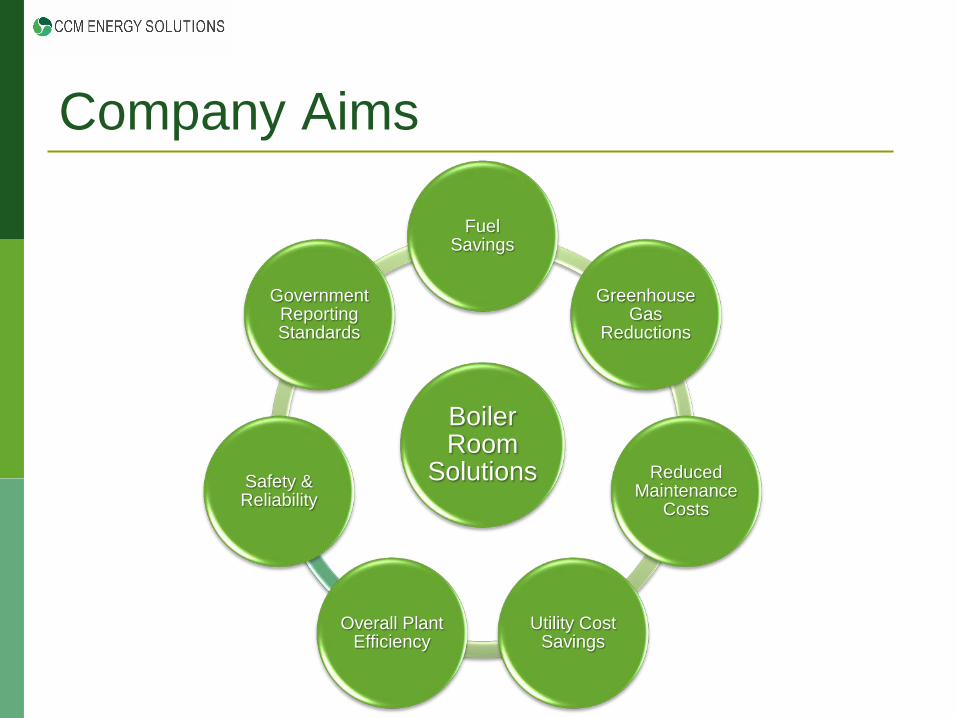
Company Aims
Boiler Room
Solutions
Fuel Savings
Greenhouse Gas
Reductions
Reduced Maintenance
Costs
Utility Cost Savings
Overall Plant Efficiency
Safety & Reliability
Government Reporting Standards

Energy Efficiency Distribute a range of energy efficient technologies
Heating boiler optimisation units (Sabien) 100kW to 2MW
High efficiency burners for hot water and steam (Limpsfield) 220kW to 62MW
Combustion management control systems (Autoflame) 1MW to 62MW
Exhaust gas analysis systems (Autoflame) Emissions monitoring & logging software (CEMS) Steam boiler controls (Autoflame)
Technical expertise

Limpsfield Burners - Overview

Limpsfield Burners - Overview High efficiency burner range
Low O2 levels (typically 2-3% throughout the range) Low CO production (sub 10ppm at low O2 levels) High turndown- at least 6:1
Reduced fuel consumption (typically over 10%) Improved combustion & thermal efficiency Improved fuel to steam/heat efficiency
Reduced Greenhouse Gas Emissions (GHG’s) Lower excess air levels (sub 15%)
Reduced maintenance requirements & operating costs Improved reliability Fewer moving parts

Limpsfield Burners - Overview Range from 220kW – 62MW (0.75-106MBtu/hr) Fuels that can be fired:
Gases- natural gas, LPG, LNG, hydrogen, biogas Oils- (light to heavy), biofuels, animal fats and by-products, solvents
Dual fuel / multi-fuel applications Low NOx applications (sub 30ppm or sub 9ppm) Pre-heat air applications (up to 2800C) Fuel inlets on both sides of burner housing offering build flexibility to suit each application Unique large rear viewing port enabling a clear view of the combustion process for commissioning, service and maintenance Simple construction allows easy access to internal components- all components can be accessed and replaced without the need to remove the burner from the boiler front

Limpsfield- 2MW Natural Gas

Case Study- NT Hospital Mechanical linkage based system Inefficient and costly Difficult to maintain and service
Limpsfield LCNO36 Dual fuel (LPG and diesel) Efficient and economic Significant reductions in:
Diesel oil usage CO2 emissions Electrical consumption

Case Study- NT Hospital
Fuel savings of 12.1%, with an annual diesel saving of 125,000 litres Annual CO2 reduction of 460 tonnes Electrical consumption reduction of 50,500kWh

Autoflame- Overview

SWITCH
BOILERDRAFT
FORCED
MOD. MOTOR
U.V
OIL
AIRPRESSURE
GAS
FLUE
FLAMESAFEGUARD
PRESSURECONTROL
P.I.D.CONTROLLER
Pre-Installation Set-Up

SENSOR SERVO
SECOND SETPOINT FACILITYEXTERNAL MODULATION
SWITCH
EXTERNAL
BOILER
DRIVECH.5SPEEDVARIABLE FLAMEOR
DRAFTFORCED AUX.
SERVO
CH.4AIR AUX.
SERVOSERVO
CH.3CH.2 U.V
LOAD OR
OIL
AIRPRESSURE
PRESSURESENSOR
OIL
CH.1FUEL
PRESSURESENSOR
GAS
GAS
HIGH/ LOW GASPRESSURE PROVING
VALVE PROVING
SENSOR
PROBESAMPLING
CH.6
FLUEVARIABLE
SPEED DRIVEEXTERNAL
T.D.S.PROBE
FEEDWATERVALVE
STEAMSENSOR
CAPACITANCEPROBES
TEMP.SENSOR
TEMP.SENSOR
SURFACEBLOWDOWN
BOTTOMBLOWDOWN
FEEDWATERSERVO
OUTSIDETEMP. SENSOR 15 X FIRST OUT ANNUNCIATION
Post Installation- Full System

Post Installation- Full System NEW 2016

Mk.8 Micro Modulation Controller 12.1” multi-touch screen display Micro Modulation- Fuel/Air ratio control UV and IR self check flame safeguard Burner safety control Gas Valve Proving- leakage detection Gas, oil and air pressure proving Precise target set point control Online data logging Historical trending FGR Management Lead lag control for both steam and hot water (I.B.S.) 5 Parameter Trim, O2, CO2, CO, Ambient Temperature & Pressure Expansion PCB for Water Level Control, Flow Metering and First-Out Annunciation

Micro Modulation- Fuel/Air Ratio Independently controlled fuel and air positioning motors with an accuracy of 0.1 of an angular degree 4 separate fuel curves 4 dedicated servo drives 2 dedicated variable speed drives Selectable trim channel (damper of VSD) Error diagnostic codes displayed Single point change facility for commissioned fuel/air ratio User definable optimum ignition position (golden start) Cold start routine to protect the boiler from cold shock

Burner Control Box Functions Full flame supervision with UV self-check for continuous operation, patented self adaptive UV amplification IR self-check Burner control functions with user configurable timings (ignition, purge, pilot and main flame proving) Gas valve proving system with on-line pressure supervision Oil pressure monitoring and display with limit checks Air windbox pressure proving- display and supervision Lockout history of last 128 incidents with date, time, function and reset Burner control functions (Flame Safeguard) selectable

Setpoint Control Features (PID) Internal 3 term PID control to required setpoint for both pressure and temperature Software adjustable thermostat/pressure stat facility Second setpoint user adjustable Time clock facility, reduced setpoint and off modes Outside temperature compensation Intelligent boiler sequencing for both steam and hot water Intelligent boiler sequencing for low pressure steam applications Fuel flow metering- instantaneous and totalised Hand/Auto/Low flame hold facilities 4-20mA input for external load control 4-20mA output of firing rate Twin burner and multi-burner control capability

Expansion PCB Features Water level control (digital or analogue) Steam flow metering through temperature sensors (no meter required) Surface blowdown
Timed or continuous through modulating valve Bottom blowdown
Blowdown based on boiler usage and firing rate Draft control
Balanced flue conditions for tall stacks First Out Annunciation
15 safety inputs for additional control Fully metered combustion and cross limiting control
Simultaneous firing of two fuels Economiser inlet & outlet temperature analysis

Case Study- Laundry
3MW Cleaver Brooks- LPG Electronic fuel / air ratio system 2:1 gear ratio for the air damper
No mechanical linkages, 90 degree servomotor movement for 45 degree air damper movement (first in Australia)
Fully modulating water level control system to maintain optimum steam output
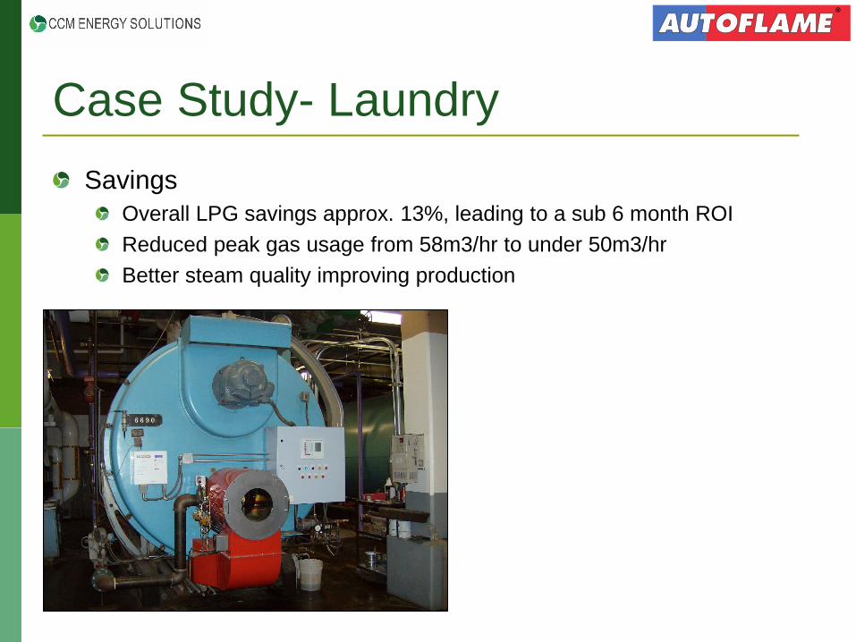
Case Study- Laundry Savings
Overall LPG savings approx. 13%, leading to a sub 6 month ROI Reduced peak gas usage from 58m3/hr to under 50m3/hr Better steam quality improving production

Exhaust Gas Analyser to report flue gas emissions Continuous and on-going measurement of flue gases
O2, CO2, CO, NO (& SO2 & NO2)
Real time analysis of emissions at your finger tips Display of efficiency, fuel usage and calculated carbon foot print Full CEMS package (Continuous Emissions Monitoring Software) Micro Processor controlled Complete diagnostic information including cell depletion Low maintenance, cost and easy installation Six 4-20mA analogue output signals Integration with combustion management system for additional savings Five parameter trim (O2, CO2, CO, Ambient Temperature & Pressure) Upper and lower limits of control on five measured parameters
O2, CO, CO2, NO & Exhaust Gas Temperature 2 years of data storage
Emissions Logging & Reporting

Exhaust Gas Analyser (EGA) User-definable time periods for analysis (hourly, daily, quarterly, annually)
View cell degradation Anticipate cell replacement requirements Plug and play cell changeover

Exhaust Gas Analyser (EGA) Total weight & volumetric emissions Per gaseous emission
Input from fuel flow meter Specify fuel characteristics Total cost of fuel

Data Transfer Interface to collate information from multiple boilers on a single site
Set point control and on/off functionality through the BMS Transfer information from multiple sites back to a single point (board room) View CO2 emissions at all sites (instantaneous and totalised) On-going review of burner/boiler performance Set parameters / limits for efficiencies of each appliance Ability to add I/O boards to integrate further devices and information Access through EtherNet allowing global analysis
Remote Monitoring & Control

Remote Monitoring & Control

Sabien Technology: M2G System Sabien Technology is the manufacturer of the patented M2G boiler load optimisation control system
A system designed to improve the efficiency of commercial heating boilers and direct fired hot water heaters
Improved boiler room efficiency leads to: Fuel Savings – typically in range of 5-25% Reduced Carbon Dioxide Emissions Typical paybacks between 6 months and 2 years
Proven technology with numerous successful case studies from the UK & USA, and recently in Australia
Over 10,000 units installed worldwide
CCM is an authorised distributor for Australia – new technology for this market

Sabien Technology Customers

Behavioural Changes
Regular boiler maintenance
BMS Weather Compensation
Boiler Sequencing
Boiler Load Optimisation
Boiler Optimisation

Boiler Load Optimisation Specifically designed to overcome the inherent problems of excessive cycling
Retrofitted onto existing boilers with no impacts to building temperatures or existing control strategies
Integrates with and complements existing boiler controls (e.g. Building Management System, sequencing, Outdoor Temperature Compensation)
Uses flow and return temperature sensors and proprietary software to regulate boiler cycling
Prevents boilers cycling on to recover standing losses; only respond to genuine calls for heat
Is widely overlooked – leaving untapped energy savings

Red sections show sporadic firing periods of <15 minutes
Pink sections show boiler firing continuously
Initial Site Analysis

Sabien- How Does it Work? Flow and return temperatures are analysed independently every 10 seconds by two digital probes (measuring every second) Intelligent and self adapting software monitors the boiler’s thermodynamic profile in real time Boiler temperature decay is monitored to distinguish dry cycling from genuine calls for heat
Should the temperature decay be more rapid from the boiler’s set point - this will indicate a genuine call for heat from the building load, rather than just standing losses
Temp
Time
Temperature over time
Boiler Temperature

The M2G measures a reference point of the flow and return temperatures when the boiler reaches the required set point and creates 2 temperature gradients The M2G measures the temperature decay of the flow and return every second to identify the true load profile of the individual boiler The M2G will prevent the boiler from firing due to dry cycling, i.e. within the deadband values.
Identifying Boiler Dry Cycling
Boiler thermostat set point
Minutes
Tem
p o C
Deadband 8oC
Boiler Flow
15 0 Minutes
Tem
p o C
Deadband 3oC
Boiler Return
Boiler T
0 15
Boiler would normally fire at this point i.e. dry cycle.
However, the M2G will prevent the boiler firing

Boiler thermostat set point
Minutes
Tem
p o C
Deadband 8oC
Boiler Flow
15 0 Minutes
Tem
p o C
Deadband 3oC
Boiler Return
Boiler T
0 15
Identifying a Genuine Call for Heat If the flow or return temperature decay is outside of the deadband values, the M2G allows the boiler to fire to meet with the genuine heating demand The M2G re-calculates these values each time the boiler reaches the required variable set point temperature This ensures the required ambient temperatures and hot water within the building are not compromised

Common Return / Flow Temperature
Variable Temp
Boiler 1 82o
Boiler 2 70o
Boiler 3 60o
BMS
Outstations Lighting etc
Air conditioning / ventilation
x 3 Boiler enable / disable
Outside Temperature
82o
60o
70o
60o
60o
60o
72o Blended
temperature
60o
Individual Boiler Analysis Dry cycling cannot be identified by measuring the blended temperatures of all the boilers connected into a common header- this must be identified at each boiler

Case Studies University in Sydney
700kW leisure complex heating boiler Boiler off less than 15mins- 356 -> 66 /week Cycling reduction- 68.1 -> 31.9 /day Nominal year-on-year reduction- 18% Degree Day adjusted savings- 9.5% Reduction in CO2 emissions- 43 tons Payback period- 1 year
Sydney Hotel
2*1MW heating boilers Nominal year-on-year reduction- 11% Reduction in CO2 emissions- 173 tons Payback period- 0.62 years
-200,000
-150,000
-100,000
-50,000
0
50,000
100,000
1-A
ug8-
Aug
15-A
ug22
-Aug
29-A
ug5-
Sep
12-S
ep19
-Sep
26-S
ep3-
Aug
10-A
ug17
-Aug
24-A
ug31
-Aug
7-S
ep14
-Sep
21-S
ep28
-Sep
Cum
ulat
ive
Fuel
Sav
ed (M
J)
CUSUM Analysis 2012 - 2013
M2G installed. Significant drop in gas consumption following
installation

Thank you Any Questions?