Embed Size (px)
Citation preview

© Fraunhofer ISE
Realistic Yield Expectations for Bifacial PV Systems – an Assessment of Announced, Predicted and Observed Benefits
Christian ReiseAlexandra Schmid
Fraunhofer Institute for Solar Energy Systems ISE
PV Performance Modelling and Monitoring Workshop
Cologne, October 23, 2015

© Fraunhofer ISE
2
Bifacial PV Modules and SystemsBifacial gain
Ratio of additional “rear side” kWh to “front only” kWh
BG = E_rear / E_front
© Fraunhofer ISE
3
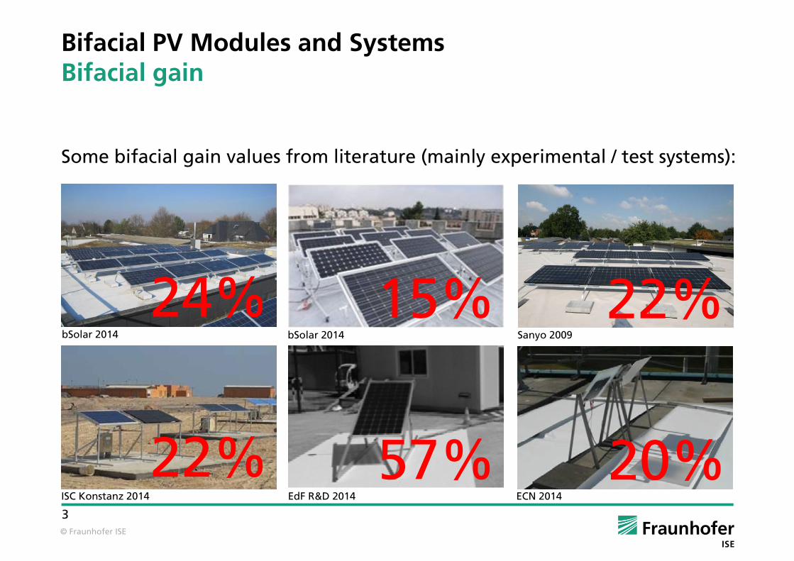
Bifacial PV Modules and SystemsBifacial gain
Some bifacial gain values from literature (mainly experimental / test systems):
24% 15% 22%
22% 57% 20%
bSolar 2014 Sanyo 2009bSolar 2014
ISC Konstanz 2014 EdF R&D 2014 ECN 2014
© Fraunhofer ISE
4
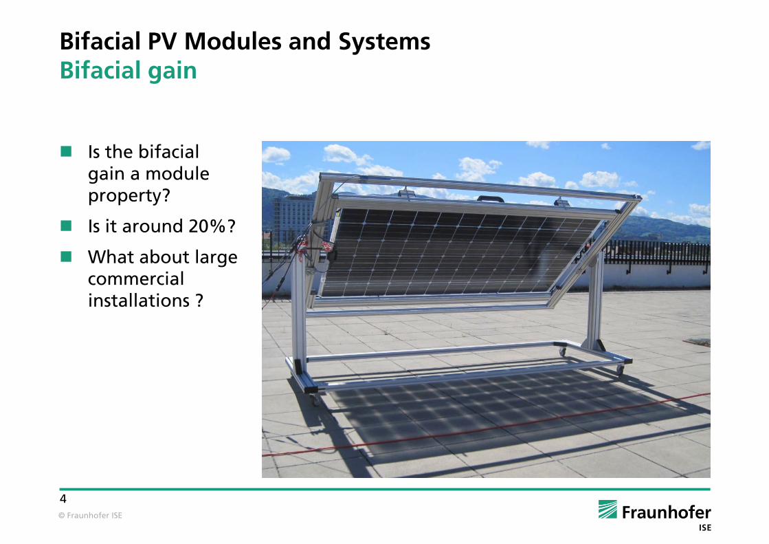
Bifacial PV Modules and SystemsBifacial gain
Is the bifacial gain a module property?
Is it around 20%?
What about large commercial installations ?
© Fraunhofer ISE
5
AGENDA
Efficiency and Power: Definitions
Predicting Bifacial Yields
Exemplary Results
Conclusion

© Fraunhofer ISE
6
Bifacial PV Modules and SystemsInfluence on bifacial gain
Yield depends on with with
monofacial bifacial modules
STC power ++ ++
module properties + ++
tilt angle + ++
height o ++
albedo + ++
mounting structure o +
... and other factors

© Fraunhofer ISE
7
Bifacial Efficiency and Power A Straight Forward Approach
Yield ~ G(front) * eff(front) + G(rear) * eff(rear)
= G(front) * eff(front) + G(rear) * eff(front) * BF
STC value optical gain bifaciality factor18% … 22% 5% … 50% 75% … 95%
these factors determine bifacial gain
module property system property module propertylaboratory software laboratory
© Fraunhofer ISE
8
Predicting Bifacial YieldsPredicting Optical Gains
No commonly used software available (the current versions of e.g. PVSYST, PV*SOL, and NREL’s SAM cannot predict optical gains)
Numerical methods from physics and optics offer different approaches:
View factor method
Ray tracing method
© Fraunhofer ISE
9
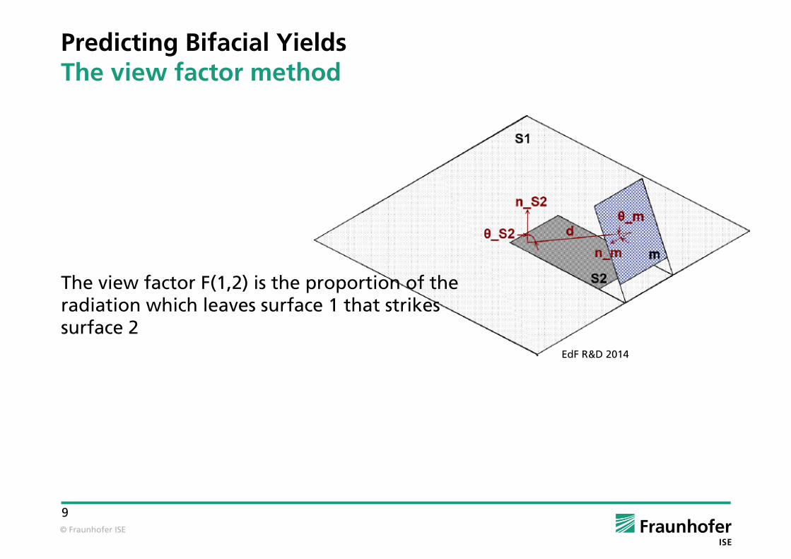
Predicting Bifacial YieldsThe view factor method
The view factor F(1,2) is the proportion of the radiation which leaves surface 1 that strikes surface 2
EdF R&D 2014

© Fraunhofer ISE
10
Predicting Bifacial YieldsThe view factor method
The view factor F(1,2) is the proportion of the radiation which leaves surface 1 that strikes surface 2
Wikimedia Commons
© Fraunhofer ISE
11
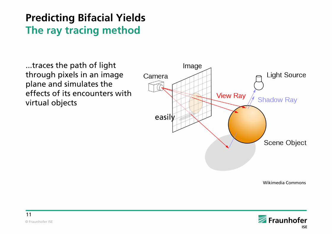
Predicting Bifacial YieldsThe ray tracing method
...traces the path of light through pixels in an image plane and simulates the effects of its encounters with virtual objects
Wikimedia Commons
easily

© Fraunhofer ISE
12
Predicting Bifacial YieldsPredicting Optical Gains
View factor method:
easy to implement for simple geometries
becomes complex task for realistic systems
Ray tracing method:
less easy to implement
time consuming
delivers rear side irradiance, rear side inhomogeneity, mutual (front side) shading, influence of mounting structure...
© Fraunhofer ISE
13
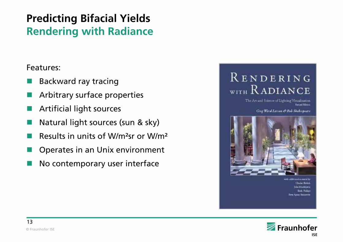
Features:
Backward ray tracing
Arbitrary surface properties
Artificial light sources
Natural light sources (sun & sky)
Results in units of W/m²sr or W/m²
Operates in an Unix environment
No contemporary user interface
Predicting Bifacial YieldsRendering with Radiance
© Fraunhofer ISE
14
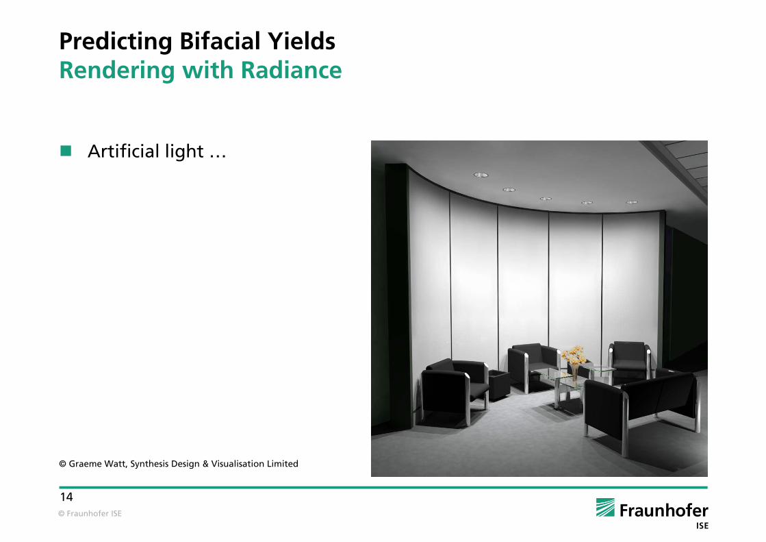
Predicting Bifacial YieldsRendering with Radiance
Artificial light …
© Graeme Watt, Synthesis Design & Visualisation Limited

© Fraunhofer ISE
15
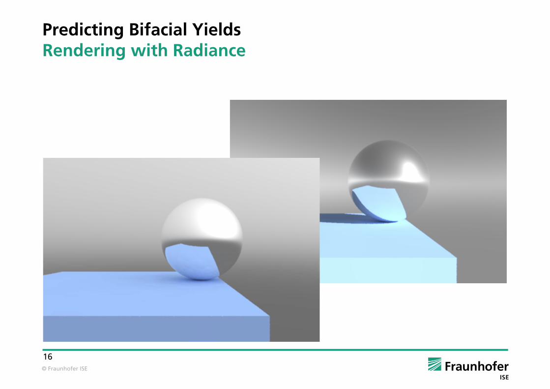
Predicting Bifacial YieldsRendering with Radiance
Natural light ...
See also: Ch. Reise, A. Kovach: PV Shading Analysis in Complex Building Geometries, 13th EUPVSEC, Nice (FR), 1995
© Fraunhofer ISE
16
Predicting Bifacial YieldsRendering with Radiance
© Fraunhofer ISE
17
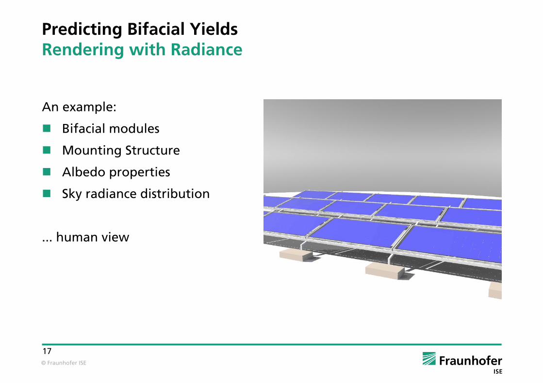
Predicting Bifacial YieldsRendering with Radiance
An example:
Bifacial modules
Mounting Structure
Albedo properties
Sky radiance distribution
... human view

© Fraunhofer ISE
18
Predicting Bifacial YieldsRendering with Radiance
An example:
Bifacial modules
Mounting Structure
Albedo properties
Sky radiance distribution
... aerial view

© Fraunhofer ISE
19
Predicting Bifacial YieldsRendering with Radiance
An example:
Bifacial modules
Mounting Structure
Albedo properties
Sky radiance distribution
... mouse view

© Fraunhofer ISE
20
Predicting Bifacial YieldsValidation I
The prototype:
Bifacial module test installation, monitored by Fraunhofer ISE in 2009

© Fraunhofer ISE
21
Predicting Bifacial YieldsValidation I
System model validation results (235 days in 2009):
height tilt angle albedo bifacial GainDC
Measurement 0,2 m 15 0,64 21.9%
Model 0,2 m 15 0,64 21.1%

© Fraunhofer ISE
22
Predicting Bifacial YieldsValidation II
Single module model validation...
© Fraunhofer ISE
23
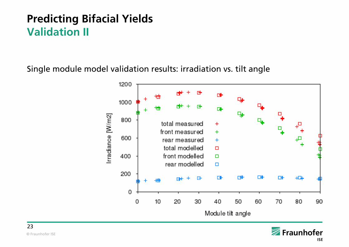
Predicting Bifacial YieldsValidation II
Single module model validation results: irradiation vs. tilt angle

© Fraunhofer ISE
24
Predicting Bifacial YieldsValidation II
Single module model validation results: I_sc vs. tilt angle

© Fraunhofer ISE
25
Exemplary Results
Bifacial modules will be installed in commercial PV projects
Commercial PV projects will follow or extend traditional installation schemes, therefore, some contradictions will arise:
module height vs. wind load with rooftop systems
optical gain vs. space requirements (GCR)
increased albedo vs. maintenance effort
Most probably, commercial PV projects will show lower bifacial gains than test or demonstration installations
© Fraunhofer ISE
26
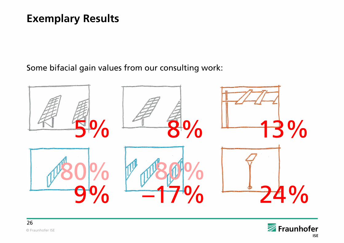
Exemplary Results
Some bifacial gain values from our consulting work:
5% 8% 13%
9% –17% 24%80% 80%

© Fraunhofer ISE
27
Exemplary Results
First example values for a rooftop system:
type height tilt angle albedo GCR Country bifacial Gain
rooftop 0.1 m 20 0,40 0,40 DE 6%
rooftop 0.3 m 20 0,40 0,40 DE 11%
rooftop 0.5 m 20 0,40 0,40 DE 14%
rooftop 0.3 m 20 0,20 0,40 DE 6%
rooftop 0.3 m 20 0,40 0,40 DE 11%
rooftop 0.3 m 20 0,60 0,40 DE 16%
© Fraunhofer ISE
28
Summary
Bifacial modules show a big potential for increased yield and / or reduced electricity costs
Bifacial gain is not a module property
Bifacial module characterization needs some proper definitions
Each system layout needs an individual assessment
Small experimental or demonstration systems show bifacial gains of 15% to 25%
With larger commercial systems, realistic bifacial gains are expected in a range from 5% to 15%
Optimization of mounting geometry and mounting structure is essential in order to draw the full benefits from bifacial PV modules

© Fraunhofer ISE
29
Thank you for your attention!
Fraunhofer Institute for Solar Energy Systems ISE
Dr. Christian Reise
www.ise.fraunhofer.de