Embed Size (px)
Citation preview
1 © 2014 ANSYS, Inc. April 22, 2015 ANSYS Confidential
Advanced Simulations of Hypertrophic Obstructive Cardiomyopathy in Human Heart using ANSYS
Can Ozcan, Vladimir Kudriavtsev, Metin Ozen

2 © 2014 ANSYS, Inc. April 22, 2015 ANSYS Confidential
Outline
• Physiology and Pathology of Hypertrophic Obstructive Cardiomyopathy
• CFX vs Fluent for FSI Setup?
• Wall Motion in Fluent
• Setting up a 3D model
• Effect of Boundary Conditions
• Effect of Turbulence Modeling
• Effect of Coupling Relaxation Factors (Key Impactor for Convergence)
• How to setup the structural part of the FSI
• A case for CFX: Immersed Body approach

3 © 2014 ANSYS, Inc. April 22, 2015 ANSYS Confidential
Human Heart Physiology (i.e. Normal Condition)
• Myocytes (contracting heart muscle cells) are at their normal size
• Ventricle volume is not squeezed from sides and allow normal out-flow into aorta
Papillary muscle
AnimationNormal_Echocardiogram.wmv

4 © 2014 ANSYS, Inc. April 22, 2015 ANSYS Confidential
Definition of the Pathological CaseCardio: Heart
Myo: Muscle
Pathy: Disease, suffering
• Mitral leaflets are large
• Papillary muscles are more anteriorly positioned
Mechanism of dynamic outflow tract obstruction. The upperschematic shows a representation of the mitral leaflets. Theelongated mitral leaflets that are drawn into the LeftVentricular Outflow Tract during early systole with midsystolicprolonged systolic anterior motion- septal contact,malcoaptation of the mitral leaflets, and the resultantposteriorly directed jet of mitral regurgitation.
AnimationNormal_Echocardiogram.wmv
5 © 2014 ANSYS, Inc. April 22, 2015 ANSYS Confidential
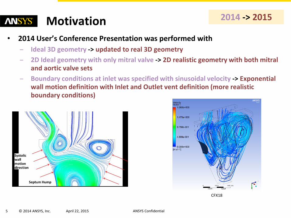
Motivation• 2014 User’s Conference Presentation was performed with
– Ideal 3D geometry -> updated to real 3D geometry
– 2D Ideal geometry with only mitral valve -> 2D realistic geometry with both mitral and aortic valve sets
– Boundary conditions at inlet was specified with sinusoidal velocity -> Exponential wall motion definition with Inlet and Outlet vent definition (more realistic boundary conditions)
CFX18
2014 -> 2015

6 © 2014 ANSYS, Inc. April 22, 2015 ANSYS Confidential
Why do we used Fluent and not CFX?
Main reason is the internal re-meshing capability
• With CFX one can do re-meshing calls automatically, but this is not available for FSI setups yet
− Fluent provides different re-meshing options like 2.5D extrusion mesh
• Some tips about re-meshing:
– Boundary layers in 2D does not work nicely
– Use coarse elements near deforming regions as oscillations may result in negative volume errors
– 2.5D re-meshing is limited to “Spring” method
− FSI surfaces are not re-meshed and keep original mesh elements (some kind of limitation here)
7 © 2014 ANSYS, Inc. April 22, 2015 ANSYS Confidential
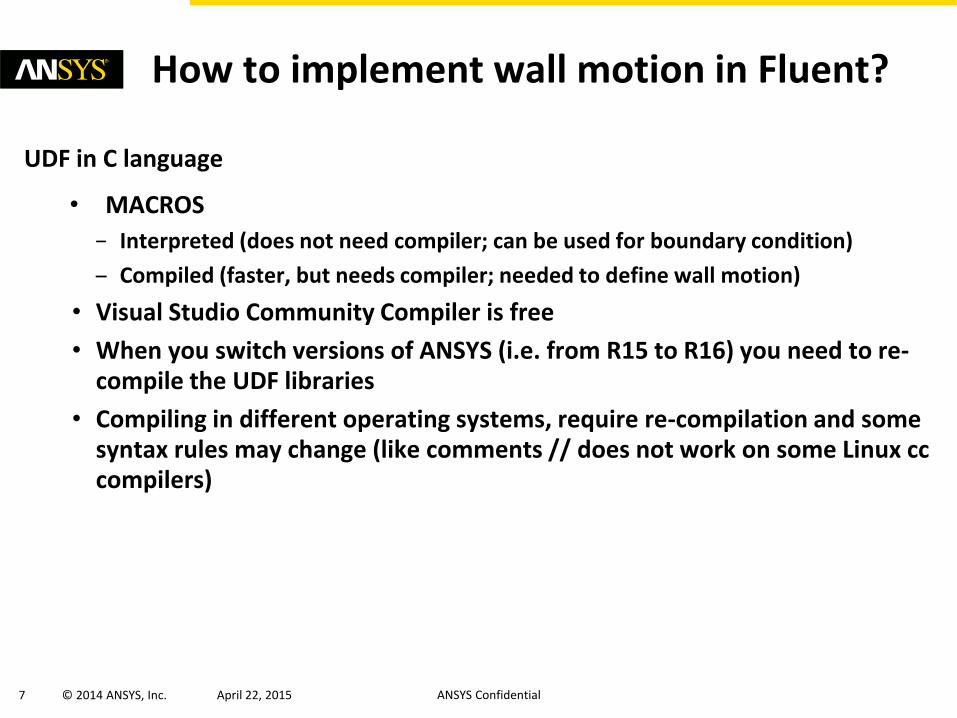
How to implement wall motion in Fluent?
UDF in C language
• MACROS
− Interpreted (does not need compiler; can be used for boundary condition)
– Compiled (faster, but needs compiler; needed to define wall motion)
• Visual Studio Community Compiler is free
• When you switch versions of ANSYS (i.e. from R15 to R16) you need to re-compile the UDF libraries
• Compiling in different operating systems, require re-compilation and some syntax rules may change (like comments // does not work on some Linux cc compilers)

8 © 2014 ANSYS, Inc. April 22, 2015 ANSYS Confidential
2D Analysis – 2.5D Analysis• For 2D problems, one can use 2.5D remeshing in Fluent (model a 3D slice to
represent the problem in 2D)
• With 2.5D remeshing one can model 3D extruded geometry as well
• 2.5D surface re-meshing method only applicable to along line extrusions
• Only triangular surfaces mesh is allowed (no mixed zones)
• Only Laplacian smoothing is available (kind of limitation for large wall deformations)
9 © 2014 ANSYS, Inc. April 22, 2015 ANSYS Confidential
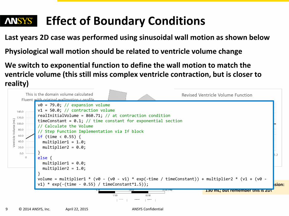
Effect of Boundary ConditionsLast years 2D case was performed using sinusoidal wall motion as shown below
Physiological wall motion should be related to ventricle volume change
We switch to exponential function to define the wall motion to match the ventricle volume (this still miss complex ventricle contraction, but is closer to reality)
In reality contraction: 50 mL Expansion: 130 mL; but remember this is 2D!
contraction
expansion
v0 = 79.0; // expansion volumev1 = 50.0; // contraction volumerealInitialVolume = 860.71; // at contraction conditiontimeConstant = 0.1; // time constant for exponential section// Calculate the Volume// Step Function Implementation via If blockif (time < 0.55) {multiplier1 = 1.0;multiplier2 = 0.0;
}else {multiplier1 = 0.0;multiplier2 = 1.0;
}volume = multiplier1 * (v0 - (v0 - v1) * exp(-time / timeConstant)) + multiplier2 * (v1 + (v0 -v1) * exp(-(time - 0.55) / timeConstant*1.5));

10 © 2014 ANSYS, Inc. April 22, 2015 ANSYS Confidential
• Wall function is set to match volume change shown here
• Mass flow is set as derivative of volume change (rho*dV/dt)
Effect of Boundary Conditions
Inlet velocity was specified
Opt-A: Inlet vent / Outlet vent
Opt-B: Inlet mass flow / Outlet pressure or vent
• Mass flow is defined to match the ventricle volume change due to wall motion
Option-A: Both Inlet and Outlet are defined as vent
Option-B: Inlet mass flowOutlet is defined as vent

11 © 2014 ANSYS, Inc. April 22, 2015 ANSYS Confidential
3D Real Heart Mesh• Preparation of the geometry is performed in ICEM-CFD
• Wall motion definition required a new wallmotion3D.c
• Ventricle volume is expanded with respect to a center point located in between mitral and aortic valves
Model courtesy of Dr. Jingwen Hu, PhDUniversity of Michigan Transportation Research Institute
Original Full Heart Geometry Left Ventricle and AtriumExtracted in ICEM
Smooth Mesh for Robust Wall Motion
Definition
12 © 2014 ANSYS, Inc. April 22, 2015 ANSYS Confidential
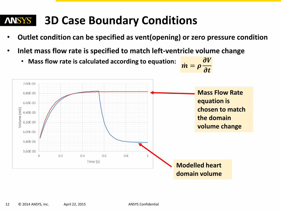
3D Case Boundary Conditions• Outlet condition can be specified as vent(opening) or zero pressure condition
• Inlet mass flow rate is specified to match left-ventricle volume change
• Mass flow rate is calculated according to equation:
Modelled heart domain volume
Mass Flow Rate equation is chosen to match the domain volume change
𝒎 = 𝝆𝝏𝑽
𝝏𝒕

13 © 2014 ANSYS, Inc. April 22, 2015 ANSYS Confidential
3D Real Heart Model• Animation. No valves modelled
• Outlet specified as vent/opening with inlet prescribed mass flow rate (see prev. slide)
Expanded @0.55s Contracted @1.0s
14 © 2014 ANSYS, Inc. April 22, 2015 ANSYS Confidential
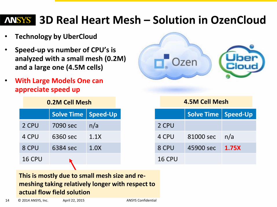
3D Real Heart Mesh – Solution in OzenCloud• Technology by UberCloud
• Speed-up vs number of CPU’s is analyzed with a small mesh (0.2M) and a large one (4.5M cells)
• With Large Models One can appreciate speed up
Solve Time Speed-Up
2 CPU 7090 sec n/a
4 CPU 6360 sec 1.1X
8 CPU 6384 sec 1.0X
16 CPU
This is mostly due to small mesh size and re-meshing taking relatively longer with respect to actual flow field solution
Solve Time Speed-Up
2 CPU
4 CPU 81000 sec n/a
8 CPU 45900 sec 1.75X
16 CPU
0.2M Cell Mesh 4.5M Cell Mesh

15 © 2014 ANSYS, Inc. April 22, 2015 ANSYS Confidential
2D Effect of Turbulence Model• Laminar vs k-omega SST turbulence model differences over
vorticity is provided below
• Inlet & Outlet condition with 5% Turbulent Intensity and 10 Viscosity Turbulent Viscosity Ratio
• Reynolds number hardly reaches 1E5
Laminar Turbulence
16 © 2014 ANSYS, Inc. April 22, 2015 ANSYS Confidential
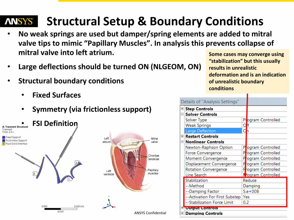
Structural Setup & Boundary Conditions• No weak springs are used but damper/spring elements are added to mitral
valve tips to mimic “Papillary Muscles”. In analysis this prevents collapse of mitral valve into left atrium.
• Large deflections should be turned ON (NLGEOM, ON)
• Structural boundary conditions
• Fixed Surfaces
• Symmetry (via frictionless support)
• FSI Definition
Some cases may converge using “stabilization” but this usually results in unrealistic deformation and is an indication of unrealistic boundary conditions

17 © 2014 ANSYS, Inc. April 22, 2015 ANSYS Confidential
Structural Setup Details (Contacts)• Contact definitions are critical to achieve robust solution in FSI setup
• Contact conditions with offset to prevent fluid elements collapsing in CFD side
• In addition to surface-to-surface contact, one should make use of edge-to-surface contacts to prevent penetration problems in valve-to-valve contact
• Stiffness factor can be decreased up to 0.01 for better convergence
ANSYS R16 Contact View Contact Definition

18 © 2014 ANSYS, Inc. April 22, 2015 ANSYS Confidential
Effect of Coupling Relaxation Factors
• Force and displacement “under relaxation factor” values limits potential large variations which may result in divergence
• Maximum number of coupling iterations should be set to allow complete convergence within each coupling step
Under relaxation factor

19 © 2014 ANSYS, Inc. April 22, 2015 ANSYS Confidential
3D CFX using immersed boundary method
• Can be used to model physiological case (i.e. normal condition)
• Valve deformation cannot be captured, so not useful for modelling hypertrophic cardiomyopathy
Showing Flow Velocity

20 © 2014 ANSYS, Inc. April 22, 2015 ANSYS Confidential
3D CFX using immersed boundary method
• Can be used to model physiological case (i.e. normal condition)
• Valve deformation cannot be captured, so not useful for modelling hypertrophic cardiomyopathy
Showing Vorticity (Velocity Curl)

21 © 2014 ANSYS, Inc. April 22, 2015 ANSYS Confidential
Next Steps
• 3D valve with re-meshing in Fluent can be implemented
• Realistic valve contraction input can be obtained from Cardiac MRI and applied using Fluent UDF(user defined functions)