Embed Size (px)
Citation preview

How SPEED Appliance is Effective in Torque Control
Effective Torque Torquing momentSliding mechanics
Enmasse retraction

©Dr Sylvain Chamberland
Effective Torque .022 slot• Torque play
! .017 x .022 = 22,3°
! .019 x .025 = 10,5°
! .021 x .021 = 5°
! .021 x .025 = 3,9°
! .020 x .025 SW ! 4°
• Effective torque
! 0°
! 5°
! 6°
! 7,1°
! ! 7°.020 x .025

©Dr Sylvain Chamberland
Effective Torque .018 slot
• Torque play
! .017 x .022 = 5,4°
! .017 x .025 = 4,5°
! .018 x .025 = 2°
• Effective torque
! 5,6°
! 6,5°
! 9°

©Dr Sylvain Chamberland
• A rectangular arch wire fitting into a rectangular slot can generate the moment of a couple necessary to control root position. !The wire is twisted (placed into torsion) as it is put into the bracket slot. !The two points of contact are at the edge of the wire, where it contacts
the bracket.
• The moment arm therefore is quite small, and forces must be large to generate the necessary MC.
• Using the same tooth, a 50 gm net lingual force would generate a 750 gm-mm moment. To balance it by creating an opposite 750 gm-mm moment within a 0.5 mm bracket, a torsional force of 1500 gm is required.
Downloaded from: Proffit: Contemporary Orthodontics, 4th edition (on 5 April 2009 03:18 PM) © 2007 Elsevier
Mc / Mf > 1

©Dr Sylvain Chamberland
• Moment of force, MF1, = F1 X D1
• Moment of couple Mc = F2 X D2
• D1 > D2
• Therefore, to produce moments of equal magnitude, the forces F2 creating the couple must be of greater magnitude than F1

©Dr Sylvain Chamberland
• Moment required to torque maxillary incisal segment
! = 3000 -3500 g-mm (Nikolai 1985)
! 1000 g-mm for 2 incisors, 2500 g-mm for 4 incisors (Burstone)
! 2000g-mm ! 20 Nmm
• To not overcome the torquing moment of 20 Nmm, the retraction force should be of low magnitude

©Dr Sylvain Chamberland
• At 12° & 24°: A-SLB > P-SLB
• At 36° of torsion
• No difference in the torquing moment between P-SLB and A-SLB
Torque expression of self-ligating brackets compared with conventional metallic, ceramic, and plastic brackets Morina et al EJO 2008 (30) 233-238
Badawi, et. al. AJODO 2008; 133:721-8 • At 20° of torsion; .019 x .025 w; .022 slot
• SPEED = 8 Nmm, torque loss 11°
• This is consistant with Badawi study: 24°! 11,8 Nmm
• One would assume that with a .020 x .25 SW or .021 x .021 x .020 torque would be first expressed at a smaller angle
• Higher torquing moment would be generated at smaller angle of twist
Nmm

©Dr Sylvain Chamberland
Comparison of torque expression between SS, TMA and CuNiti in metallic SLB AO 2010 #80; 884-889
Damon 3MX
In-Ovation-R
SPEED
• Speed and In-Ovation-R: Ealier engagement of torque at 5°•Damon 3Mx: Engagement at 10-12°
•At 36°: Mean torque difference within 5% between all brackets when SS was compare with either NiTi or TMA
•At 24° • SS ! 1.5 to 1.8 times the torque of TMA • SS ! 2.5 times the torque of Niti

©Dr Sylvain Chamberland
Damon Q
In-Ovation-R
SPEED NTP
•At 25° of twist: Mc ! 35Nmm•No statistic " between the 3 Bk
•At 20° of twist: Mc ! 21 Nmm• More than Morina et al because it is measured at the bk
and not at 10 mm away
• SPEED brackets that clip did not opened have similar torque curve as Damon and In-Ovation R
TwinDashed line = expressed torque
• Conclusion"Bracket
deformation occurs above 30° of twist
"Likely a significant factor in loss of torque expression for both SLB and conventional Bk
Journal of Dental Biomechanics Vol 2010 (2010), Article ID 397037, 7 pages
Mechanical effects of 3rd movement in SLB by the measurement of torque expression AJODO 2011;139:e31-e44
©Dr Sylvain Chamberland
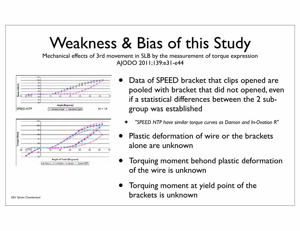
Weakness & Bias of this Study
Mechanical effects of 3rd movement in SLB by the measurement of torque expression AJODO 2011;139:e31-e44
• Data of SPEED bracket that clips opened are pooled with bracket that did not opened, even if a statistical differences between the 2 sub-group was established
! "SPEED NTP have similar torque curves as Damon and In-Ovation R"
• Plastic deformation of wire or the brackets alone are unknown
• Torquing moment behond plastic deformation of the wire is unknown
• Torquing moment at yield point of the brackets is unknown
SPEED-NTP N = 14

©Dr Sylvain Chamberland
• H1: A 45° or so angle of twist in a .019 X .025 SS wire do not create plastic deformation
Home Made Fancy Study
• H1: REJECTED

©Dr Sylvain Chamberland
• H2: A 45° or so angle of twist do not debond a bracket
Home Made Fancy Study
• H2: REJECTED

©Dr Sylvain Chamberland
Home Made Fancy Study
• H3: A 45° or so angle of twist create plastic deformation of the bracket
• Since bond failure occurred, a fancy lab study is required
• To know at which angle and torquing moment bracket deformation occurs, a non deformable material should be used instead of a SS wire

Torque play of various SLB

©Dr Sylvain Chamberland
What are the limits of 1/-SN
1/-SN = 126°1/-SN = 72° 1/-SN = 103°- 31° + 23°

©Dr Sylvain Chamberland
• A single force applied at the crown create uncontrolled tipping which improve incisor torque
! The crown move in the opposite direction of the root
16SC for 6 weeks !16x22 neost for 6 weeks !20x25 nitisw for 6 weeks !21x21 Dwire
GR 21-06-1020x25 nitisw
GR 20-09-1021x21DW
GR 01-11-1016x22 neost

©Dr Sylvain Chamberland
• 16SC (6 w) !16x22 neost (6 w) !20x25 nitisw (6 w) !21x21 Dwire (6 w) !Stop ABP, bond 6's/ & 7's/, 16x16sent (6 w) ! 20x20neost (6 w) !20x25 niti (6 w) !20x25 SS (6 w) ! 20x25 SS + ART (6 w)
• Significant torque increased was obtained in 65 weeks through a progression of at least 5 wires
• 28° is below the angle at which bracket deformation could occur
1/-SN = 72° 1/-SN = 100°+28°

©Dr Sylvain Chamberland
Wire progression = torque correction
+14°
•.016SC (6w)!.018SC (6w) !.020x.020NiTi (12w) !!.020x.025 Niti (12w)!.020x.025 SW (16w)!!.021x.025SS
1/-SN = 96°
Em.Ja. 0910
1/-SN = 82°
Em.Ja. 0909
•Torque has improved with engagement of full size archwire

©Dr Sylvain Chamberland
MxMd advancement for OSA
Em.Ja. 0909 Em.Ja. 0611

©Dr Sylvain Chamberland
Maintain torque while retracting
Se.Ma. 0308
1/-SN = 112°
Se.Ma. 0810
1/-SN = 96°-16°•.016SC (6w)!.016x.022Niti (8w) !!.020x.020NiTi (14w) !.019x.025 TMA (10w)!!.021x.021x.020 retmasse SW (12m)!!.021x.021Dwire SS
• Maintain low force module while retracting to not overcome Mc generated at the bracket interface• Increased wire cross section to increase stiffness
in torsion and reduce torque play • Mx & Md advancement is planned

©Dr Sylvain Chamberland

©Dr Sylvain Chamberland
Ja.Le. 0808 Ja.Le. 0510
Maintain initial torque
• .016SC (12w)!.018SC (16w) !.016x.022NiTi (6w) !!.020x.025 Niti (6w)!.019x.025 TMA (12w) !!.020x.025 Niti (6w) ! .020x.025 SW (8w)
• 1/1 improved because /1-MP improved• Early engagement of full dimensional archwire
helped to maintain adequate torque
103° to 104° = maintain

©Dr Sylvain Chamberland
Ectopic lateral incisor
• Early engagement of rectangular wire and 0° torque Bk on lateral incisor was efficient and effective to obtain alignement in the 3rd order plane of space• .020 x.020 Niti!.020x.025Niti!
!.020x.025SW• Finishing: .021x.025SS (8 m)
Lateral incisors Bk prescription: 0°

©Dr Sylvain Chamberland
• Aim: to assess the slot dimensions in the 0.022-inch bracket of an upper left central incisor, in six different commercially available self-ligating bracket systems, using electron microscopy, in order to determine the accuracy of manufacturers published dimensions
• SmartClip, Clarity SL, SPEED, Damon MX, In-Ovation R, In-Ovation C
Assessment of Slot Sizes in Self-ligating Brackets using Electron Microscopy
N.B. BHALLA, S.A. GOOD, F. MCDONALD, M. SHERRIFF, A.C.CASH

©Dr Sylvain Chamberland
• Results! All of the brackets systems measured had slot sizes that
were significantly greater than their stated 0.022-inch dimension
! Speed brackets (Strite Industries) were 5.1% larger, and found to be the closest dimensions to those published.
! The largest bracket was the Smartclip bracket (3M) measured to be 14.8% bigger than 0.022 inches
Assessment of Slot Sizes in Self-ligating Brackets using Electron Microscopy
N.B. BHALLA, S.A.GOOD, F.MCDONALD, M.SHERRIFF, A.C.CASH Aust Orthod J 2010, may 26

©Dr Sylvain Chamberland
• Clinical implication
! Increased slot dimensions reduces the expression of bracket prescription in all three dimensions.
! Dimensional inaccuracies lead to teeth moving by tipping, rather than bodily movement.

©Dr Sylvain Chamberland
Orthodontic Bracket Manufacturing Tolerances and Dimensional Differences between SLB
Major T et al, J Dental Biomechanics, v 2010
• SPEED: Smaller than nominal height, larger at bottom than the top
• In-Ovation: Taper!Smaller at the bottom, larger at the top
• Damon: Larger than nominal height
Nominal height=0,559 mm

©Dr Sylvain Chamberland
Orthodontic Bracket Manufacturing Tolerances and Dimensional Differences between SLB
Major T et al, J Dental Biomechanics, v 2010
• Tolerance of slot height of SPEED = 15#m smaller than nominal
• Tolerance of slot height of In-Ovation = 15#m smaller at bottom & bigger at the top
• Tolerance of slot height of Damon Q = 43#m bigger (oversized)
• An oversize/undersize of 15#m means ±2,3° of torque play
• An oversize/undersize of 43#m means ±4,7° of torque play and a reduced torque expression (Mc) of 5-10 Nmm
• Difference between SPEED and Damon = 15 + 43#m or 7° of torque play

©Dr Sylvain Chamberland
• If an .022" slot bracket is actually .0235" (~ 7%)
! An .019 X .025 or an .0215 X .028 archwire will have 5° of wire bracket play beyond that usually anticipated for an .022" slot.
• When protracting posterior teeth,
! If the mechanics depend upon moments generated at the incisor brackets with rectangular archwires, the above slot-size errors can induce lingual tipping of the incisors
! Such results are undesirable, to say the least. If the archwires are smaller than their stated sizes, the impact is even worse
SIATKOWSKI, JCO 1999, p 509
TABLE 1TIPPING DUE TO LOSSOF TORQUE CONTROL*
Torque Loss5° 8° 10°
Maxillary 1.3mm 2.1mm 2.7mmMandibular 1.2mm 1.9mm 2.3mm
*Lingual change in incisal edge position (incisors of average dimensions).

Tooth translationEnmasse retraction
Phases of treatment

©Dr Sylvain Chamberland
Some thoughts about friction
• Most study are bench study
! Test .019 x .025 SS wire or similar
• Bracket held steady (no angulation) & wire is pulled at a rate of 10 mm/ minute (Stefanos S., Secchi A. et al, AJODO 2010)
• Bracket sliding on a steady wire at a rate of 1 mm/minute (Budd S., Dask J. Tompson B. EJO 2008; Oliver C. Dask J. Tompson B. AO 2011)
SUCH CONDITIONS NEVER OCCUR CLINICALLY

©Dr Sylvain Chamberland
Change over time in canine retraction: an implant study
Parsekian, R, Bushang, P.H., Gandini L.G., Rossouw P.E., Am J Orthod Dentofacial Orthop 2009;136:87-93

©Dr Sylvain Chamberland
Rate of tooth movement
• 10 mm / minute ! 432 000 mm per month
• 1 mm / minute ! 43 200 mm per month
• Average of 1,42 mm / month ! 0,00003287 mm per minute

©Dr Sylvain Chamberland
Some other thoughts about friction
• Findings:
! Passive SLB produce less frictional resistance than Active SLB
! However, this decreased friction may result in decreased control compared with actively ligated systems
• All wire tested were rectangular ! activate the clip (active zone)

©Dr Sylvain Chamberland
• If bracket held steady (no angulation)
! RS is lower for all SLB than for conventional bracket tied with wire or an elastomeric ligature and lower with passive clip than active
• This condition never occurs clinically!

©Dr Sylvain Chamberland
• As soon as the corners of the bracket contact the wire (2nd order), binding occurs, and this contribute most of the resistance to sliding
• Binding do not appear to be affected by the method of ligation
• Same binding and notching could be expected in the 1st order
# Heavy forces = more rotation and anchorage lossYee et al, AJODO 2006; 136:150.e1-150.e9

©Dr Sylvain Chamberland
• Clinical studies support the view that resistance to sliding has little to do with friction and, instead, is largely a binding-and-release phenomenon that is about the same with conventional and self-ligating brackets.
• The limited clinical trial data now available do not support the contention that treatment time is reduced (presumably because of lower friction) with self-ligating brackets
Friction Conclusion
Friction and resistance to sliding in orthodontics: a critical review. AJODO 2009; 135:442-7

©Dr Sylvain Chamberland
Ligature derived force
• Depends on ligation mode
! Can be smaller in SLB or greater in conventional systems
"Shear force increase linearly with wire deflection relative to the bracket slot
"Friction resistance is proportional to the grade of the wire securing elements rigidity and to the extent of wire deflection
• Correlation between passive clip design and wire surface scratching
Reznikov, N et al, Measurement of friction forces between stainless steel wires and reduced-friction self-ligating brackets, AJODO 2010; 138:330-8

©Dr Sylvain Chamberland
• Some clip flexibility might provide a considerable benefit during the working stage of the orthodontic treatment, when residual malalignment of the teeth still persists.
• Either an active clip or an elastomeric module can absorb minor, clinically undiscernible tooth irregularities and does not hinder sliding mechanics.
• In contrast, a passive clip demands ideal alignment of the teeth subjected to a retraction force.
Reznikov, N et al, Measurement of friction forces between stainless steel wires and reduced-friction self-ligating brackets, AJODO 2010; 138:330-8

©Dr Sylvain Chamberland
Therefore
• Swinging the teeth on a very small wire
• Few if any friction is involved:
! Passive zone
! No binding
! No notching
Wi.Be.290609 Wi.Be.250909Wi.Be.120809
Wi.Be.131109 Wi.Be.100510

©Dr Sylvain Chamberland
• The width of the bracket on a tooth determines the length of the moment arm (half the width of the bracket) for control of mesiodistal root position. • Bracket width also influences the contact angle at which the corner of
the bracket meets the arch wire. The wider the bracket, the smaller the contact angle.• In the 1st order, the clip prevent rotation and help reduce the moment
arm in that plane
Downloaded from: Proffit: Contemporary Orthodontics, 4th edition (on 5 April 2009 03:23 PM)© 2007 Elsevier

©Dr Sylvain Chamberland
Do We Need a Fancy Study to...
• Know that .019x.025 TMA (or SS) will generate more Friction (FR) than a smaller wire ?
• Know that increased retraction force will cause more tipping of the tooth to retract and therefore Binding (BI) and Notching (NO) is more likely to occur?
An.No 310308
Resistance to slide

©Dr Sylvain Chamberland
Do We Need Fancy Study to...
• Know that .020 SS wire has less friction than .019x.025?
An.No 250608
Resistance to slide

©Dr Sylvain Chamberland
Do We Need Fancy Study to...
• Know that pulling on 1 side and pushing from the other side make it easier to translate teeth over a rounded corner of an anterior arch form?
Resistance to slideAn.No 110309
An.No 081209

©Dr Sylvain Chamberland
Do We Need Fancy Study to...
• Know that T loop retraction springs are...frictionless?

©Dr Sylvain Chamberland
Sliding a single tooth
• .021 x .021 x .020 HDG
• Elastomeric chain 7-6-5-o-3
! Round wire to reduce Friction
! Lower force to reduce Binding & Notching
Re.Ba. 0906
Re.Ba. 0107
Re.Ba. 1007
Re.Ba. 0907

©Dr Sylvain Chamberland
Sliding a single tooth
• .021 x .021 x .020 HDG
• Compressed coil 22-24
! Round wire reduced Friction
! Low force reduced Binding & Notching
• Auxilliary wire .016
• .016 x .022 HA niti
Re.Ba. 0906
Re.Ba. 0107
Re.Ba. 0907
Re.Ba. 1007

• Mx: 021x021x020: #13 is retracted individually
Es.Gr1210
• Md: 021x021x020: #46 is protracted + upright spring to increase anchorage
• Mx: $ E link: space is opening mesially
• Md: New 021x021x020 X 58 mm ! To include 1st premolar! Increase wire stiffness
• Mx: $ 020 SS wire. ! Class I canine achieved ! Elastomeric chain activated ~ 2 mm
for the lateral
• Md: $ E link
Es.Gr0111
Es.Gr0311

©Dr Sylvain Chamberland
Rate of tooth movement under heavy and light continuous orthodontic forces
Yee J.A., Elekdag-Türk T., Cheng LL, Darendeliler MA, AJODO 2009; 136:150e1-150e9
• Initial tooth mvt benefits from light forces
• Heavy forces increased rate of tooth mvt and amount of canine retraction BUT increased anchorage loss and loss of canine rotation control
• Maximum anchorage cases benefits from light forces

©Dr Sylvain Chamberland
Tipping and translating
• Distal tipping + rotation
• T-loop for root uprighting
Am.Bu. 0800
Am.Bu. 0101 Am.Bu. 1000
Am.Bu. 0500

©Dr Sylvain Chamberland
Hills DUAL-GEOMETRY Wire™
• Made of an ultra-high tensile strength stainless steel for optimum stiffness.
• Full sized square anterior section fills the slot of optimal torque control
! Torque play = 5°; Effective torque ! 6°
• Rounded posterior section is polished to minimize friction
! Estimated torquing moment: ~ 15 Nmm
.021 X .021 X .020

©Dr Sylvain Chamberland
Hills DUAL-GEOMETRY Wire™
Anterior section - square
Posterior section- round
•Mx:!38 mm: to include 4 incisors!55 mm: to include canine to canine
•Md:!45 mm: to include canine to canine!58 mm: 1st premolar to 1st premolar

©Dr Sylvain Chamberland
En masse retraction
Downloaded from: Proffit: Contemporary Orthodontics, 4th edition (on 3 May 2007 06:18 PM)© 2007 Elsevier
• .021 X .021 X .020 Hills Dual geometry
• Cl I module: E-Link E-5
! Force 100 to 125 g
• Reverse curve of Spee
! Moment to counteract tipping
! Posterior toe in or constriction

©Dr Sylvain Chamberland
• Translation: ~ 100 g
! To maintain torque control when closing space
! Use low force module
Force system
Downloaded from: Proffit: Contemporary Orthodontics, 4th edition (on 3 May 2005
(M/F =10:1)

©Dr Sylvain Chamberland
01-03
11-03
05-03
• Enmasse space closure
! 021 X 025 SS + oxydoreduction of the posterior section distal to 1st premolar
• Molar protraction
! Note that flat curve of Spee is maintained

©Dr Sylvain Chamberland
08-04
09-04
11-04
Enmasse retraction: Anchorage A
• .021 x .025 SS DG
! Upright spring on /3's
! E5, 75g/side
! Protraction of lower 5's
• .021 x .021 x .020 HDG
! OJ and Cl I molar relationship is improving
$ E-links 5
$ E-links 5

©Dr Sylvain Chamberland
12-04
01-05
03-05
• Use cl II to improve molar relationship
• Upright spring to PM2
• E6 47-P; E5 P-36

©Dr Sylvain Chamberland
Molar protraction
01-05 03-05
09-04 11-04 12-04
04-05
• Time: 8 months
• Note space opening between the premolar and the molar

©Dr Sylvain Chamberland
.021 x .025 SS + oxydoreduction
Space close in 5 months
Flat curve of Spee is maintained
Pa.Ge.0803
Pa.Ge.1003
Pa.Ge.0104

©Dr Sylvain Chamberland
• Adult, cl II div 1, missing #36
• Tx plan:_________
Ka.Sw.200504
Ka.Sw.050804

©Dr Sylvain Chamberland
• Note space opening distal to 46 & 37
• Once 46 is contacting 44, start protraction of 47
Ka.Sw.300505 at 1 year into tx
Ka.Sw.210905

©Dr Sylvain Chamberland
• TPA removal, reassessment of Bk position, cl II elastic
Ka.Sw.191005

©Dr Sylvain Chamberland
• Duration: 108 weeks
Ka.Sw.160106
Ka.Sw.260606
Ka Sw

©Dr Sylvain Chamberland
Moment / Force
• Problem
! Loss of incisor torque
! Mx: reverse curve of spee
! Md: increased curve of spee
•Solution: Mc > MF
–Increase moment at the wire/bk interface!! wire stiffness!RC in Md!AC in Mx
–Reduced force level
Mc / Mf > 1

©Dr Sylvain Chamberland
Molar protraction
• Enmasse .021 x .021 x .020
• E-links : 7's - hook
Fo.Mi 1208
Fo.Mi 0206
Fo.Mi 0407

©Dr Sylvain Chamberland
Mi.Fo. 0206
Mi.Fo. 1208

©Dr Sylvain Chamberland
Molar protraction
• Enmasse .021 x .021 x .020
• E-links : 6's - hook
• Uprighting spring 17-15
! to overcome tipping in the 2nd orderDa.Ga.210209 Da.Ga.300910

©Dr Sylvain Chamberland
Molar protraction
• Such large protraction of the 2nd molar resulted in mesial rotation in the 1st order
• Class I force module from the lingual helped to correct rotation in the 1st order while the uprighting spring corrected the tipping in the 2nd order
Da.Ga. 0109 Da.Ga. 0410 Da.Ga. 0910

©Dr Sylvain Chamberland
2nd Molar Protraction
Na.Ru.140907
Tx initiated: Dec 07
Na.Ru.261009
Na.Ru.030809 At 19 m
At 23 m
Na.Ru.121010
Na.Ru.121010 At 34 m

©Dr Sylvain Chamberland
Enmasse incisor retraction
• .017 x .025 ß-Ti mushroom wire
• Preactivation bend
! Accentuated curve of Spee
! Anterior step up
! Posterior toe in
• Activation
! Pull & cinch

©Dr Sylvain Chamberland
Bé.-De. Sa 120802
• .017 x .025 TMA mushroom loop
Frictionless anterior retraction
Bé.-De. Sa 220902

Phases of treatmentFinishing

©Dr Sylvain Chamberland
SPEED Wire™
•Active • Passively seated• Actively maintained
• Spring-Clip activated by "cam" action of SPEED archwire
• Archwire and archwire slot in perfect alignment
• Torque play on top• Wire is seated at the
bottom of the slot
Seating the spring clip 0.01 mm created an arc of 5,4 mm at the apex
• Torque play! .020 x .025 ! 4°
• Effective torque! .020 x .025 ! 7°

©Dr Sylvain Chamberland
Other finishing wireD-Wire
D-Wire• Torque play
! .021 x .021 = 5°
• Effective torque! .021 x .021 = 6°
.019 x .025 SS or %-Ti
• Torque play! .019 x .025 = 10.5°
• Effective torque! .019 x .025 = ±9°
(for the lower anteriors)! .019 x .025 = 5°
(for upper anteriors)
.020 x .020 SS• Torque play
! .020 x .020 ! 6°to 7°
• Effective torque! .020 x .020 ! 4° to 5°

©Dr Sylvain Chamberland
Finishing
• Prior to surgery .020 x .025 SW + finishing bend
• Root torque achieved
Ca.Gr.0309Ca.Gr.0907
Ca.Gr.0907 Ca.Gr.1208 Ca.Gr.0309
Ca.Gr.1208

©Dr Sylvain Chamberland
3rd order problem
• Most of my problems encountered in the 3rd order plane of space where caused because I used (from 1998 to 2005) an undersized .019 x .025 archwire (SS or %-Ti)during finishing stage
• Since I reintroduced .020 X .025 or .021 X .025 archwire, I significantly reduced the needs of torquing spring in finishing except for a few particular situations
Ev. Ca.0507 Ev. Ca.0309
Ev. Ca.0909
Lingual root torqueLabial root torque

©Dr Sylvain Chamberland
Torque issue in finishing stage
Da.Pa 0908.
Da.Pa 0706
Da.Pa 280109
• Engaging a continuous archwire will cause 3rd order discepancy that will need to be address in the finishing stage
• .020 x .025SS was engaged in June. Torquing spring were added in september• Adequate alignement of incisors's talon was achieved in January

©Dr Sylvain Chamberland
• Tx time = 130 weeks
• Got it straight + a new born baby
An.No 05-7, tx initiated 0607
An.No 12-09

©Dr Sylvain Chamberland

©Dr Sylvain Chamberland
• Tx time: 92 weeks
• Slight residual midline deviation
Ja.Le. 07-8, tx initiated 0808
Ja.Le. 05-10
Md deviation

©Dr Sylvain Chamberland$ issues explain /8's

©Dr Sylvain Chamberland
• Tx time: 92.7 weeks
Ta.Po. 09-08, tx initiated 011008
Ta.Po. 12-07-10
11 y. 4 m.

©Dr Sylvain Chamberland
1/ :Torque improved

©Dr Sylvain Chamberland
Class IIISevere ALD
Vi.Lé.02-10-07
• Hopeless #16 (UR 1st molar)
• Mx midline deviated to the right

©Dr Sylvain Chamberland
• Dentoalveolar Protrusion
• Lower lip procumbency

©Dr Sylvain Chamberland
Tx planning
• Tx goals
! Reduce lip procumbency
! Obtain coincident midline
! Achieve cl I canine
! Achieve cl I molar on the left
! Achieve cl III molar on the right
• Extraction: ?

©Dr Sylvain Chamberland
• Mx:.020 x .020 neost + .016 SC
• Md: .021 x .021 x .020 enmasse retract.
Vi.Lé.03-07-08

©Dr Sylvain Chamberland
• At 50 weeks
• Mx: .016 X .022 neost; #13 engaged
Vi.Lé. 01-10-08

©Dr Sylvain Chamberland
• Reassessment of bracket position
! 14, 13, 12, 11, 22, 23, 24, 33

©Dr Sylvain Chamberland
• At 67 weeks
• Mx & Md: .019 x.025 Resol, finishing bend
Vi.Lé. 28-01-09

©Dr Sylvain Chamberland
• At 75 weeks
• Mx: .019 x .025 resol., finishing bend 21, 12
• Md: .020 x .025 SW, finishing bend 43, 45
Vi.Lé. 23-03-2009

©Dr Sylvain Chamberland
• At 87 weeks or 20 months
Vi.Le. 15-06-09

©Dr Sylvain Chamberland
Vi.Le. 0609