Embed Size (px)
Citation preview

What Is Dose?• Volume Computed Tomography Dose Index (CTDIvol) is a
standardized parameter to measure Scanner Radiation Output– CTDIvol is NOT patient dose
– CTDIvol is reported in units of mGy for either a 16-cm (for head exams) or 32-cm (for body exams) diameter acrylic phantom
– For the same technique settings, the CTDIvol reported for the 16-cm phantom is about twice that of the 32-cm phantom
– The reported CTDIvol is based on measurements made by the manufacturer in a factory setting
• In these slides, the term "patient dose" is used to describe the absorbed dose to a patient, while the generic term "dose" refers to CTDIvol

How is CTDIvol related to patient dose?
• CTDIvol is not patient dose
• The relationship between the two depends on many factors, including patient size and composition
• AAPM Report 204 introduces a parameter known as the Size Specific Dose Estimate (SSDE) to allow estimation of patient dose based on CTDIvol and patient size
• For the same CTDIvol, a smaller patient will tend to have a higher patient dose than a larger patient
What is Dose?

How is CTDIvol related to patient dose?
Both patients scanned with the same CTDIvol Patient dose will be higher for the smaller patient
CTDIvol = 20 mGy CTDIvol = 20 mGy
120 kVp at 200 mAs 120 kVp at 200 mAs
32 cm Phantom
32 cm Phantom
What is Dose?

How is CTDIvol related to patient dose?
Smaller patient scanned with a lower CTDIvol Patient doses will be approximately equal
What is Dose?
CTDIvol = 10 mGy CTDIvol = 20 mGy
120 kVp at 100 mAs 120 kVp at 200 mAs
32 cm Phantom
32 cm Phantom

Size Specific Dose Estimate (SSDE)
• AAPM report 204 describes a method to calculate SSDE using CTDIvol
• Conversion factors based on patient size (e.g., AP or lateral width, effective diameter) are provided to estimate patient dose for a patient of that size
• However, SSDE is still not the exact patient dose, as factors such as scan length and patient composition may differ from the assumptions used to calculate SSDE
• SSDE is not dose to any specific organ, but rather the mean dose in the center of the scanned volume
What is Dose?

Dynamic Scan Mode Notes
• In the Dynamic Scan Mode multiple acquisitions covering the same body region are acquired. Examples of these study types include:– Perfusion Studies– Bolus Tracking Studies– Test Bolus Studies
• Dynamic Scans often have large CTDIvol values because the scanner reports the sum of the CTDIvol values from each rotation
• The reported CTDIvol is NOT skin dose or organ dose
Acquisition Parameter Settings

Table Feed/Increment• Is the movement of the table through the bore of
the scanner over a full 360 degree rotation• Units: millimeters/rotation or millimeters/second• The parameter is known both as Table Feed
(helical/spiral acquisition) & Table Increment (axial acquisition)
Table Feed affects CTDIvol through its inclusion in Pitch (discussed later)
Acquisition Parameter Settings

Detector Configuration• Is the combination of the number of data channels and the width of the
detector associated with each data channel • The Detector Configuration determines the Beam Width or Beam
Collimation (nT), which is the number of channels (n) times the detector width associated with each data channel (T)
• For a selected detector width per data channel, a smaller total Beam Collimation usually has a higher CTDIvol than a larger Beam Collimation– Example: On a 16 slice scanner with a detector width per channel of 1.25 mm,
a collimation of 4x1.25mm is generally less dose efficient than a collimation of 16x1.25mm
Users should monitor CTDIvol values when changing detector configuration
Acquisition Parameter Settings

Acquisition Parameter Settings
Detector Configuration

Pitch• Is the Table Feed per gantry rotation divided by the beam
width/collimation• Pitch is the ratio of two distances and therefore has no units• Users should monitor other parameters when changing Pitch.
The scanner may or may not automatically compensate for changes in Pitch (for example, by changing the tube current) to maintain the planned CTDIvol.
CTDIvol ∝ 1/Pitch: Hitachi, Toshiba (no AEC)
CTDIvol independent of Pitch: GE, Siemens, Philips, Neusoft, Toshiba (AEC)
Acquisition Parameter Settings

Pitch• CTDIvol may not change in the expected manner
if the scanner automatically adjust other parameters when the pitch is changed
• The relationships between CTDIvol and pitch for the different vendors are described below – CTDIvol inversely proportional to change in pitch:
Hitachi, NeuroLogica
– CTDIvol constant when pitch is changed due to changes to other parameters: GE, Neusoft, Philips and Siemens
– The relationship between CTDIvol and pitch depends on scan mode or Software version: Toshiba

Pitch < 1Beam Width has some overlap at each view angle from rotation to
rotation
Pitch = 1No overlap of Beam
Width at each view angle and no view angles not covered at certain table
positions
Pitch > 1Some view angles are
not covered by the beam width at certain table
positions
Acquisition Parameter Settings
Pitch
Exposure Time per Rotation• Is the length of time, in seconds, that the X-ray beam is “on”
during a gantry rotation – It takes into account the gantry rotation time and angular
acquisition range• Units: seconds• Users should monitor other parameters when changing
Exposure Time per Rotation. The scanner may or may not automatically compensate for changes in Exposure Time per Rotation(for example, by changing the tube current)
CTDIvol ∝ Exposure Time per Rotation Hitachi, NeuroLogica, Toshiba (no AEC)
CTDIvol independent of Exposure Time per Rotation:
GE, Siemens, Philips, Neusoft, Toshiba (AEC)Acquisition Parameter Settings

Exposure Time per Rotation
• CTDIvol may not change in the expected manner if the scanner automatically adjust other parameters when the exposure time per rotation is changed
• The relationships between CTDIvol and exposure time per rotation for the different vendors are described below – CTDIvol proportional to change in parameter: Hitachi and NeuroLogica
– CTDIvol constant when the parameter is changed due to changes to other parameters: GE, Neusoft, Philips and Siemens
– The relationship between CTDIvol and the parameter depends on scan mode or Software version: Toshiba

Tube Current• Determines the number of electrons accelerated
across the x-ray tube per unit time• Units: milliAmperes (mA)
• CTDIvol is directly proportional to Tube Current
CTDIvol ∝ Tube Current
Acquisition Parameter Settings
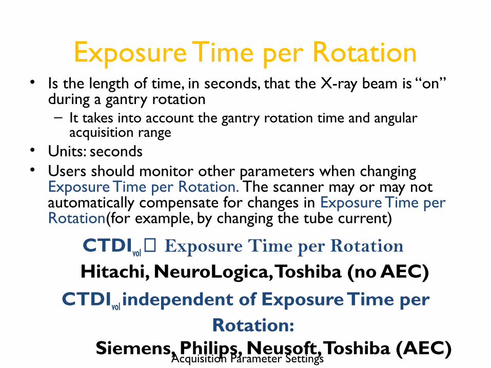
Tube Potential• Is the electrical potential applied across the x-ray tube
to accelerate electrons toward the target material• Units: kiloVolts (kV or kVp)• CTDIvol is approximately proportional to the square
of the percentage change in Tube Potential
Acquisition Parameter Settings
n
old
new
kV
kV
∝volCTDI n ≈ 2 to 3

Tube Current Time Product• Is the product of Tube Current and the Exposure
Time per Rotation• Units: milliAmpere-seconds (mAs)
• CTDIvol is directly proportional to Tube Current Time Product
CTDIvol ∝
Tube Current Time Product
Acquisition Parameter Settings

Effective Tube Current Time Product
• Is the product of the Tube Current and the Exposure Time per Rotation divided by the Pitch
• Units: milliAmpere-Seconds (mAs)• CTDIvol is directly proportional to Effective Tube
Current Time Product
CTDIvol ∝
Effective Tube Current Time Product
Acquisition Parameter Settings

Field Of Measurement• Is the diameter of the primary beam in the axial
plane at the gantry iso-center• Units: millimeters (mm)• CTDIvol may decrease with a decrease in the Field of
Measurement– The relationship is vendor specific
Users should monitor the CTDIvol values when changing the Field of Measurement
Acquisition Parameter Settings

Beam Shaping Filter• Is the scanner component that modifies the energy
spectrum and spatial distribution of the primary beam• Beam Shaping may include a bow tie filter and/or flat
filters• CTDIvol is affected by a change in Beam Shaping Filters
– The relationship is vendor and filter specific
Users should monitor CTDIvol values when changing the Beam Shaping Filter
Acquisition Parameter Settings

Acquisition Parameter Settings SummaryParameter Relationship to CTDIvol
Scan Mode Changes in the Scan Mode may affect CTDIvol
Table Feed/Increment Table Feed affects CTDIvol through its inclusion in Pitch
Detector Configuration Decreasing the Beam Collimation typically, but not always, increases the CTDIvol
Pitch CTDIvol relationship to pitch is vendor dependent
Exposure Time Per Rotation
CTDIvol relationship to exposure time per rotation is vendor dependent
Tube Current CTDIvol ∝ Tube Current
Tube Potential CTDIvol ∝ (kVp1/kVp2)n n ~ 2 to 3
Tube Current Time Product
CTDIvol ∝ Tube Current Time Product
Effective Tube Current Time Product
CTDIvol ∝ Effective Tube Current Time Product
Field of Measurement Changes in the Field of Measurement may affect CTDIvol
Beam Shaping Filter Changes in the Beam Shaping Filter may affect CTDIvol

Dose Modulation and Reduction
• Many CT scanners automatically adjust the technique parameters (and as a result the CTDIvol) to achieve a desired level of image quality and/or to reduce dose
• Dose Modulation and Reduction techniques vary by scanner manufacturer, model and software version

Automatic Exposure Control (AEC)
• Automatically adapts the Tube Current or Tube Potential according to patient attenuation to achieve a specified image quality– Automatic adjustment of Tube Current may not occur when Tube Potential is
changed
– Centering the patient in the gantry is VITAL for most AEC systems
• AEC aims to deliver a specified image quality across a range of patient sizes. It tends to increase CTDIvol for large patients and decrease it for small patients relative to a reference patient size
The use of Automatic Exposure Control may decrease or increase CTDIvol depending on the patient size and body area imaged and
image quality requestedDose Modulation and Reduction

Image Quality Reference Parameter
• Is the AEC parameter that is set by the user to define the desired level of image quality
• Changing the Image Quality Reference Parameter will affect the CTDIvol
The effect on CTDIvol when changing the Image Quality Reference Parameter is
vendor dependent
Dose Modulation and Reduction

Image Quality Reference Parameter
• A change in the Image Quality Reference Parameter will affect the CTDIvol
• Setting the parameter for “increased” image quality (e.g., lower noise) will result in more dose
• Setting the parameter for “decreased” image quality (e.g., more noise) will result in less dose
Dose Modulation and Reduction
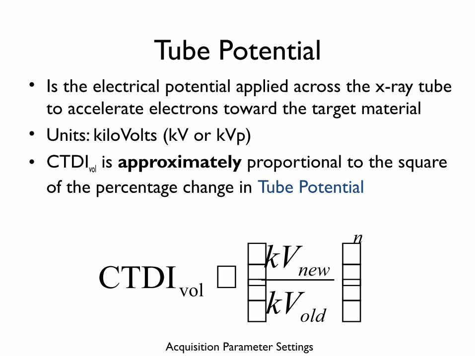
Angular Tube Current Modulation• Is an AEC feature that adjusts the Tube Current as
the x-ray tube rotates around the patient to compensate for attenuation changes with view angle
• Angular Tube Current Modulation is used to adjust the Tube Current to attempt to deliver similar dose to the detector at all view angles
The use of Angular Tube Current Modulation may decrease or increase CTDIvol depending on the patient size and body area imaged
and image quality requested
Dose Modulation and Reduction

Angular Tube Current Modulation
• Angular Tube Current Modulation uses information from one or two view localizers
Dose Modulation and Reduction

Longitudinal Tube Current Modulation
• Is an AEC feature that adjusts the Tube Current as patient attenuation changes in the longitudinal direction
• The CT Localizer Radiograph is used to estimate patient attenuation
The use of Longitudinal Tube Current Modulation may decrease or increase CTDIvol
depending on the patient size and body area imaged and image quality requested
Dose Modulation and Reduction

Longitudinal Tube Current Modulation
• Longitudinal Tube Current Modulation uses information from one or two view localizers
Dose Modulation and Reduction

Angular and Longitudinal Tube Current Modulation
• Is an AEC feature that incorporates the properties of both Angular and Longitudinal Tube Current Modulation to– Adjust the Tube Current based on the patient’s
overall attenuation – Modulate the Tube Current in the angular (X-Y)
and longitudinal (Z) dimensions to adapt to the patient’s shapeThe use of Angular and Longitudinal Tube
Current Modulation may decrease or increase CTDIvol depending on the patient size and body
area imaged and image quality requestedDose Modulation and Reduction

Angular and Longitudinal Tube Current Modulation
Dose Modulation and Reduction

ECG-Based Tube Current Modulation
• Is an AEC feature used with prospectively gated cardiac imaging that adjusts the Tube Current based on the phase within the cardiac cycle
• There are important heart rate considerations to take into account when using prospective gating
The use of ECG-Based Tube Current Modulation with prospective gating will
decrease CTDIvol compared to retrospective gating
Dose Modulation and Reduction

ECG-Based Tube Current Modulation
Dose Modulation and Reduction
Radiation OnMultiple heart beats and table positions may be
required to collect all of the data required to reconstruct the FOV including the heart

Organ-Based Tube Current Modulation• Is an AEC feature that allows for the tube current
to be decreased or turned off over radiosensitive organs on the patient periphery, such as the breasts or eye lenses
• To maintain image quality, tube current may need to be increased at other view angles
The use of Organ-Based Tube Current Modulation may reduce the absorbed dose
to organs at the surface of the body but may increase the absorbed dose to other organs
Dose Modulation and Reduction

Gantry Gantry
Conventional Organ-Based Modulation
Dose Modulation and Reduction
Organ-Based Tube Current Modulation

Automatic Tube Potential Selection• Is an AEC feature that selects the tube potential
according to the diagnostic task and patient size in order to achieve the desired image quality at a lower CTDIvol
The use of Automatic Tube Potential Selection is intended to decrease CTDIvol while achieving
the image quality required for a specific diagnostic task and patient attenuation
Dose Modulation and Reduction

Automatic Tube Potential Selection
• Tube Potential is not modulated in the same fashion as Tube Current
• It does not change with different tube positions (view angles) around the patient
• The Tube Potential for a specific patient, anatomic region and diagnostic tasks is selected and held constant for that acquisition, though it may be changed to a different tube potential for a different diagnostic taskDose Modulation and Reduction

Iterative Reconstruction• Is a feature that uses the information acquired
during the scan and repeated reconstruction steps to produce an image with less “noise” or better image quality (e.g., higher spatial resolution or decreased artifacts) than is achievable using standard reconstruction techniques
The use of Iterative Reconstruction by itself may not decrease CTDIvol; with use of Iterative
Reconstruction, image quality will change and this may allow a reduction in the CTDIvol by adjusting the
acquisition parameters used for the exam
Dose Modulation and Reduction

Iterative Reconstruction
• Iterative Reconstruction may be completed using data in Image Space, Sinogram Space or a Model Based Approach
• Changing/Turning On the %/Level of the iterative reconstruction used may or may not affect the CTDIvol of the scan and will affect the image quality of the final set of images
• In consultation, the Radiologists and Medical Physicists at an institution may adjust the acquisition parameters for studies reconstructed using iterative reconstruction based on the imaging task, the patient population, the desired image quality, dose concerns and the needs of the interpreting RadiologistDose Modulation and Reduction

Noise Reduction Using Other Post Processing Software
• Other commercially available products can be used to reduce image noise in already reconstructed images
• In consultation, the radiologists and medical physicists may adjust the acquisition parameters to reduce the CTDIvol used for studies that will be processed using these products, taking into consideration the imaging task and patient population, dose concerns, and the needs of the interpreting radiologist(s) Dose Modulation and Reduction

Dose Display• Information about the CTDIvol planned for each
scan is typically displayed before the exam on the user console
• Information about the CTDIvol delivered by each scan is typically reported in a data page or DICOM structured dose report
• Dose information provided after the exam typically also includes the DLP and the CTDI phantom size. These may also be included in information displayed before the scan.

Display of Planned CTDIvol
• CTDIvol is displayed before a study is performed based on the selected technique parameters
• It is important to check CTDIvol before a study is performed to ensure that the output of the scanner is appropriate for the specific patient and diagnostic task
CTDIvol is displayed for each planned acquisition
Dose Display

Post Study Data Page
• Following the completion of a study, a Post Study Data Page is created that includes information on the delivered CTDIvol and DLP and the phantom size used to calculate these values
• Information is displayed for each series
Dose Display

Post Study Data Page - CTDIvol
• CTDIvol is displayed for each series after a study is performed and is calculated based on the technique factors used to acquire the data
• It is useful to check CTDIvol after a study is performed to ensure that the output of the scanner was as expected
CTDIvol is displayed for each completed acquisition
Dose Display

Post Study Data Page - DLP• DLP is displayed for each series after a study is
performed and is calculated based on the technique factors and scan length used
DLP is displayed for each completed acquisition and is typically summed for all of
the acquisitions
Dose Display

Post Study Data Page – CTDI Phantom
• The CTDI Phantom used for each acquisition in the study is typically displayed
• Different phantoms may be used to calculate the CTDIvol for different acquisitions in the same study (and may vary by vendor)– Head and C-Spine Example• Body Phantom used to report CTDIvol for C-Spine portion
of exam
• Head Phantom used to report CTDIvol for Head portion of exam
Dose Display

Summing Dose Report Values
• CTDIvol values for separate series are NOT to be summed to give a “total” CTDIvol for a study– This is especially true if the series cover different
anatomic regions
• DLP is typically summed over all series in the Post Study Data Page to provide an estimate of the total patient exposure– Extreme care should be taken when considering
summed DLPs because different phantoms may have been used to calculate the CTDIvol values used to determine DLP
• A medical physicist should be contacted if patient specific dose estimates are required
Dose Display

Dose Notification Levels
• Notification Levels may be set on a CT scanner for each series within an exam protocol
• If the planned CTDIvol is above the Notification Level and triggers the notification, the user has the opportunity to edit or confirm the technique settings
• Notification Levels may be exceeded when appropriate for a specific patient or diagnostic task (e.g., in very large patients or contrast bolus monitoring scans)Dose Display

Dose Alert Levels
• Dose Alert Levels require specific action by the operator to continue scanning
• Dose Alert Levels are typically much higher than Notification Levels and take into account all series within the exam
• Triggering a Dose Alert requires that the operator confirm the protocol and settings are correct by entering in his or her name. Optionally, sites may require that the operator provide a brief explanation in the provided field
Dose Display

Radiation Dose Structured Reports
• Radiation Dose Structured Reports (RDSRs) are provided in newer software versions in a defined DICOM format
• They provide the most complete set of information regarding the irradiating events
• The reports are very detailed and require an RDSR viewer for easy visualization of relevant information
Dose Display

Questions
• Please contact the medical physicist providing support for your CT practice, your lead technologist, supervising radiologist or manufacturer’s application specialist with questions regarding these important topics and concepts.

Acknowledgements
• AAPM– Dianna Cody, Dustin Gress, Michael Heard, Jim Kofler,
Cynthia McCollough, Mike McNitt-Gray, Bob Pizzutiello, Mark Supanich
• ACR– Mark Armstrong, Penny Butler, Dina Hernandez
• ASRT– Virginia Lester
• DICOM– David Clunie, Kevin O’Donnell
• FDA– Thalia Mills

Acknowledgements
• GE– John Jaeckle
• Hitachi– Mark Silverman
• Philips– Amar Dhanantwari
• Neusoft– Keith Mildenberger
• Neurologica– Donald Fickett
• Siemens– Christianne Liedecker
• Toshiba– Kristen Boedecker
• MITA– Brian Abraham

32 cm Phantom
32 cm Phantom
How is CTDIvol related to patient dose?
Patients have equivalent SSDE
CTDIvol = 10 mGySSDE = 13.2 mGy
CTDIvol = 20 mGySSDE = 13.2 mGy
120 kVp at 100 mAs
27 cm9 cm
What is Dose?
120 kVp at 200 mAs

Why Use CTDIvol?
• CTDIvol provides information about the amount of radiation used to perform the study
• CTDIvol is a useful index to track across patients and protocols for quality assurance purposes
• CTDIvol can be used as a metric to compare protocols across different practices and scanners when related variables, such as resultant image quality, are also taken in account
• The ACR Dose Index Registry (DIR) allows comparison across institutions of CTDIvol for similar exam types (e.g., routine head exam)
What is Dose?

Dose Length Product
• The Dose Length Product (DLP) is also calculated by the scanner
• DLP is the product of the length of the irradiated scan volume and the average CTDIvol over that distance
• DLP has units of mGy*cm
What is Dose?

Useful Concepts/Terms
• The relationships between acquisition parameters and CTDIvol described in the following slides assume all other parameters are held constant
• The relationship between a parameter and CTDIvol is often described as proportional in some way– The symbol ∝ is used to indicate “proportional to”
• Directly proportional means that a change in the parameter results in the same change in CTDIvol
– Example: Doubling the rotation time from 0.5 to 1.0 seconds will double the CTDIvol
• Inversely proportional means that a change in a parameter has the opposite effect on CTDIvol
– Example: Doubling the pitch from 1 to 2 will reduce the CTDIvol by half

Acquisition Parameter Settings
• Acquisition Parameters define the technique that will be used and how the scan will proceed
• Acquisition Parameters are set in the user interface where scans are prescribed
• Changing a single Acquisition Parameter while holding everything else constant will typically affect the CTDIvol for that scan
• The following slides describe what that affect is for each parameter

Scan Mode• CT Scanners offer a variety of Scan Modes which
describe how the table moves during an exam• Scan Modes include– Axial– Helical or Spiral – Dynamic
The Acquisition Parameters that affect CTDIvol may change amongst different
Scan Modes
Acquisition Parameter Settings