Embed Size (px)
Citation preview
INTRODUCTION
HISTORY
USES
COMPOSITION AND STRUCTURE
POLYMERIZATION MECHANISMS
CLASSIFICATION
PROPERTIES
BIOCOMPATIBLITY
MANIPULATION
SPECIAL TECHNIQUES

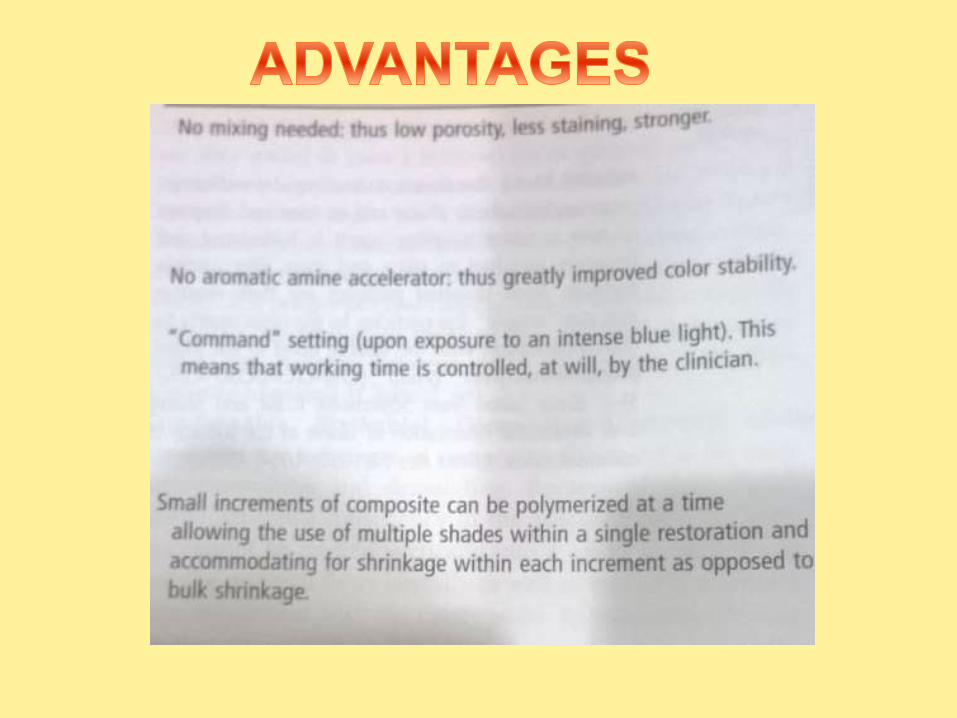
ADVANTAGES
DISADVANTAGES
RECENT ADVANCEMENTS


WHAT ARE
COMPOSITES???
A SOLID FORMED,FROM TWO OR MORE DISTINCT PHASES THAT
HAVE BEEN COMBINED TO PRODUCE PROPERTIES SUPERIOR TO
OR INTERMEDIATE TO THOSE OF INDIVIDUAL CONSTITUENTS.

TOOTH ENAMEL AND DENTIN ARE ALSO SOME OF THE NATURAL
COMPOSITES PRESENT IN NATURE.
COMPOSITE
BA

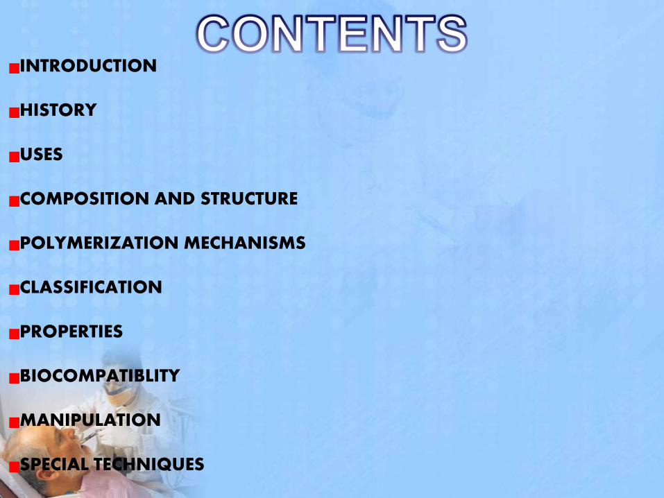
1962
Bisphenol A glycidyl methacrylate- (bis-GMA) and organic silane coupling agent
PMMA + QUARTZ
1940-1950
PMMA
20TH CENTURY
SILICATES

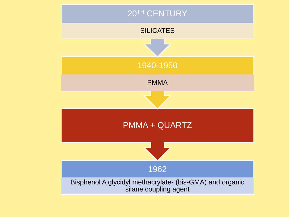
1950 198019701960 1990 2000 2010
Originaldevelopment
MACROFILLEDSelf-cure
composites
MID-FILLEDComposites
MICROFILLEDComposites
MID-FILLEDComposites
MIDI HYBRIDComposites
FLOWABLE
PACKABLE
MINI HYBRIDComposites
LOW SHRINKAGEComposites
NANOFILLED &NANOHYBRIDComposites
Non bondedcomposites
Acid etching &Enamel bonding
Dentin bondedComposites
Self-cured
UV-cured
Visible light-cured
Composite refinements
Reviewing last 55 years
3 part,2 part,1 partDentin bonding system

USES
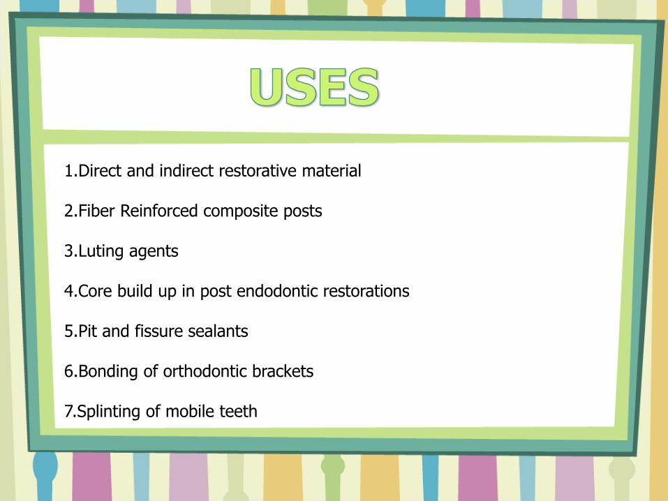
1.Direct and indirect restorative material
2.Fiber Reinforced composite posts
3.Luting agents
4.Core build up in post endodontic restorations
5.Pit and fissure sealants
6.Bonding of orthodontic brackets
7.Splinting of mobile teeth

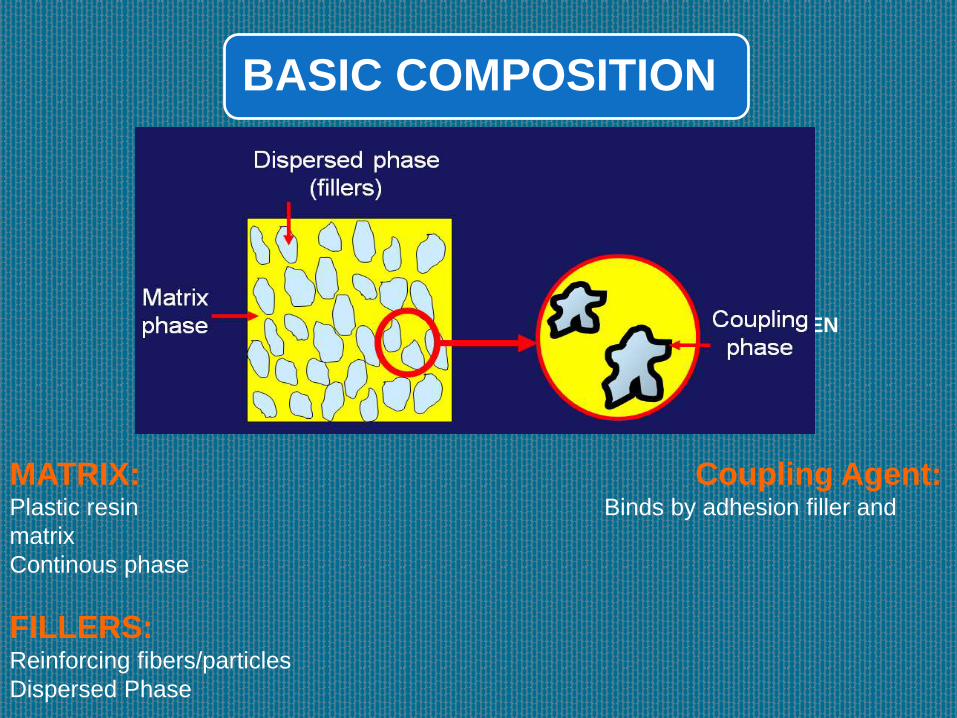
BASIC COMPOSITION
MATRIX
FILLERS
COUPLING AGEN
MATRIX: Coupling Agent:Plastic resin Binds by adhesion filler and
matrix
Continous phase
FILLERS:Reinforcing fibers/particles
Dispersed Phase

•Activator-Initiator-Soft moldable material hard durable mass
•Pigments-Matching tooth color
•Inhibitor- storage time, working time in chemically activated
composites
•UV Absorbers- Color stability

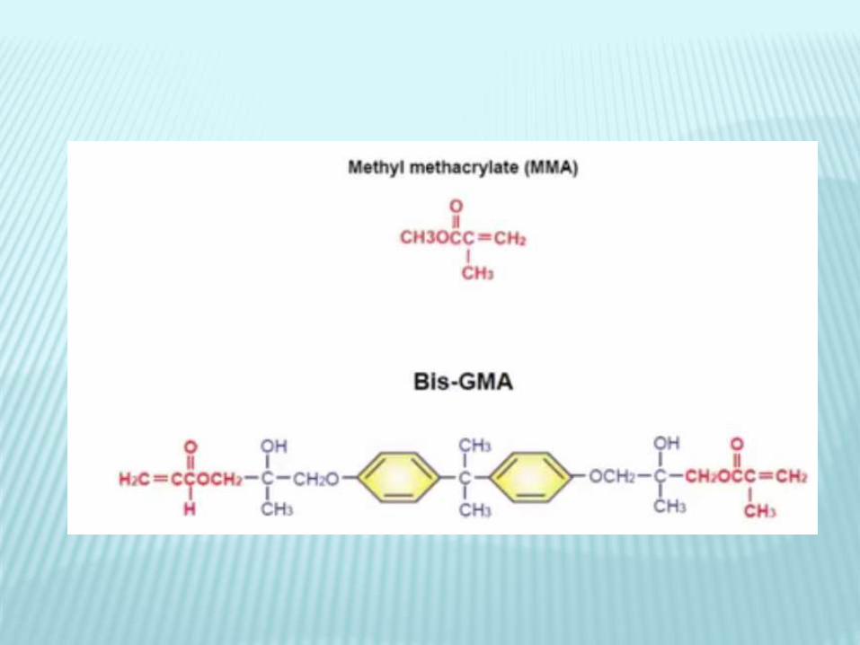
Most widely used
Aliphatic/Aromatic dimethyl acrylate monomers like
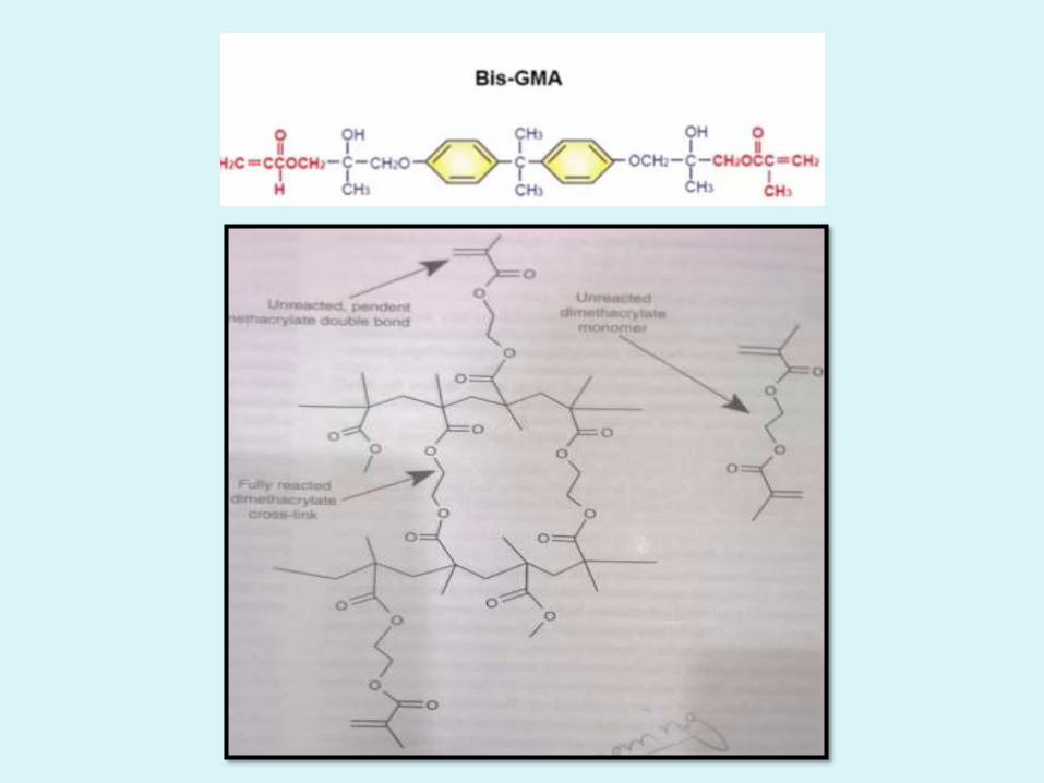
Bis-GMA
TEGDMA UDMA
MOST RECENTLY USED ARE THE SILORANE
MONOMERS

• POLYMERIZATION SHRINKAGE
• CROSS LINKING INCREASED – IMPROVED PROPERTIES
• STRENGTH,RIGIDITY
BUT DUE TO HIGH DENSITY THESE MONOMERS ARE VISCOUS AND
DIFFICULT TO MANIPULATE
TEGDMA(Dilutent monomer) + BISGMA(Viscous) Decreases Viscosity
easy to manipulate and paste like consistency


IMPROVE THE MECHANICAL PROPERTIES
DECREASE POLYMERIZATION SHRINKAGE
DECREASE THERMAL EXPANSION AND
CONTRACTION
DECREASE WATER SORPTION
RADIO OPACITY

QUARTZ:•Chemically inert
•Very hard and difficult to grind
•Difficult to polish
•Abrades opposing tooth
SILICA:•Less harder than quartz
•Non crystalline structure
GLASSES WITH HEAVY METALS:•Radio opaque
•Less inert
•Slowly leach out
•Shorter lifetime

FLOURIDE RELEASING FILLERS:
•Ability to release flourides
•Ytterbium triflouride and Ba-Al-
flourosilicates

Effect of filler size and distribution
The COMPOSITE properties are IMPROVED to a
great extent by increasing the filler loading.
This can be achieved by PARTICLES SIZE and
DISTRIBUTION

PARTICLES SIZE DISTRIBUTION
VOIDS/GAP
S

FILLER SIZE
LARGER PARTICLES
SCATTERING OF LIGHT
OPACITY
DECREASED CURING DEPTH
ROUGH SURFACE TEXTURE
STAINS,PLAQUE ETC
SMALL PARTICLES
LESS SCATTERING OF LIGHT
LESS OPACITY
INCREASED CURING DEPTH
SMOOTH SURFACE TEXTURE
HIGHER AESTHETICS
PARTICLES SIZE IN REFERENCE TO WAVELENGTH OF VISIBLE
LIGHT


•These bond the filler particles to the matrix
•They improve properties of resin by transferring stresses
from plastic resin matrix to stiff filler particles
•Prevent Leaching
•Organosilanes are most commonly used coupling agents
•Gamma methacryloxypropyl trimethoxysilane

Gamma methacryloxypropyl trimethoxysilane
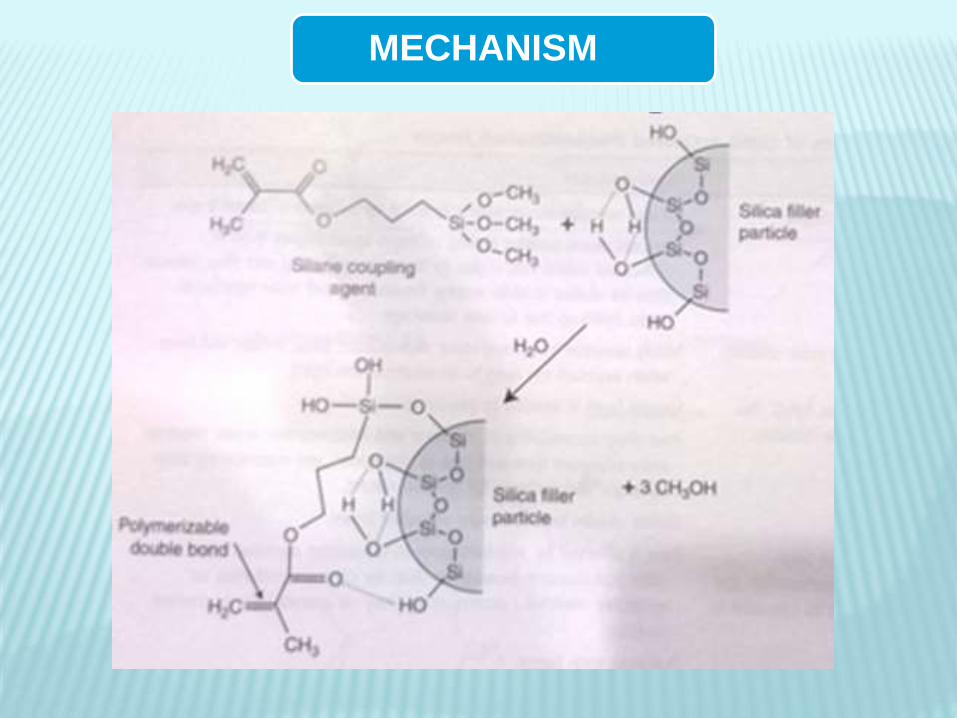
MECHANISM
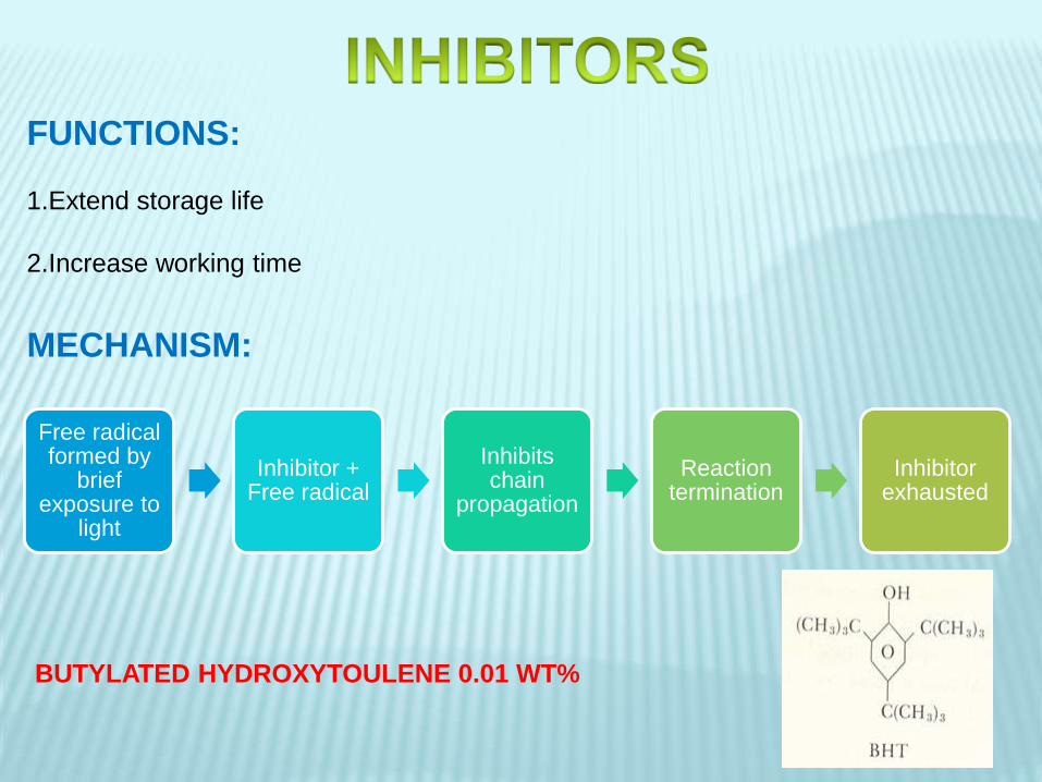
FUNCTIONS:
1.Extend storage life
2.Increase working time
Free radical formed by
brief exposure to
light
Inhibitor + Free radical
Inhibits chain
propagation
Reaction termination
Inhibitor exhausted
MECHANISM:
BUTYLATED HYDROXYTOULENE 0.01 WT%
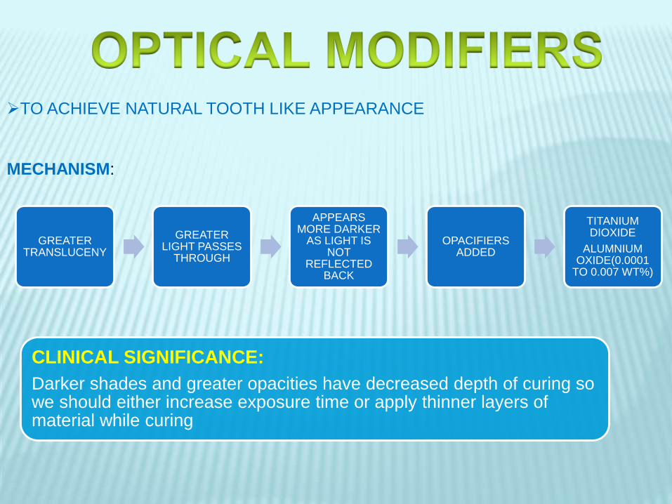
TO ACHIEVE NATURAL TOOTH LIKE APPEARANCE
MECHANISM:
GREATER TRANSLUCENY
GREATER LIGHT PASSES
THROUGH
APPEARS MORE DARKER
AS LIGHT IS NOT
REFLECTED BACK
OPACIFIERS ADDED
TITANIUM DIOXIDE
ALUMNIUM OXIDE(0.0001
TO 0.007 WT%)
CLINICAL SIGNIFICANCE:
Darker shades and greater opacities have decreased depth of curing so we should either increase exposure time or apply thinner layers of material while curing

ADDITION POLYMERIZATION
CHEMICAL ACTIVATED RESIN
ACTIVATOR-
AROMATIC TERTIARY AMINE
INITIATOR-
BENZOYL PEROXIDE
LIGHT ACTIVATED RESINS
PHOTOSENSITIZER-
CAMPHOR QUINONEINITIATOR-AMINE
ACTIVATOR-VISIBLE BLUE LIGHT

Types
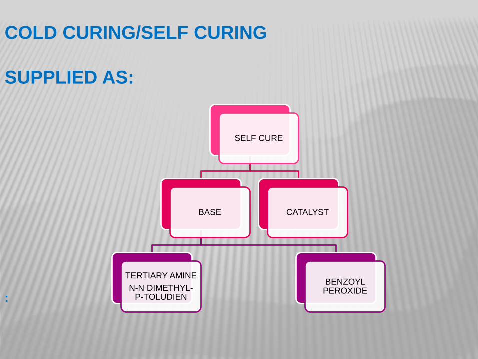
COLD CURING/SELF CURING
SUPPLIED AS:
SELF CURE
BASE
TERTIARY AMINE
N-N DIMETHYL-P-TOLUDIEN
BENZOYL PEROXIDE
CATALYST
:
POLYMERIZATION:
ADDITION POLYMERIZATION
REACTION STARTS AS SOON AS THE TWO PASTES ARE MIXED

ADDITION POLYMERIZATION
INDUCTION
ACTIVATION INITIATION
PROPAGATION CHAIN TRANSFER TERMINATION
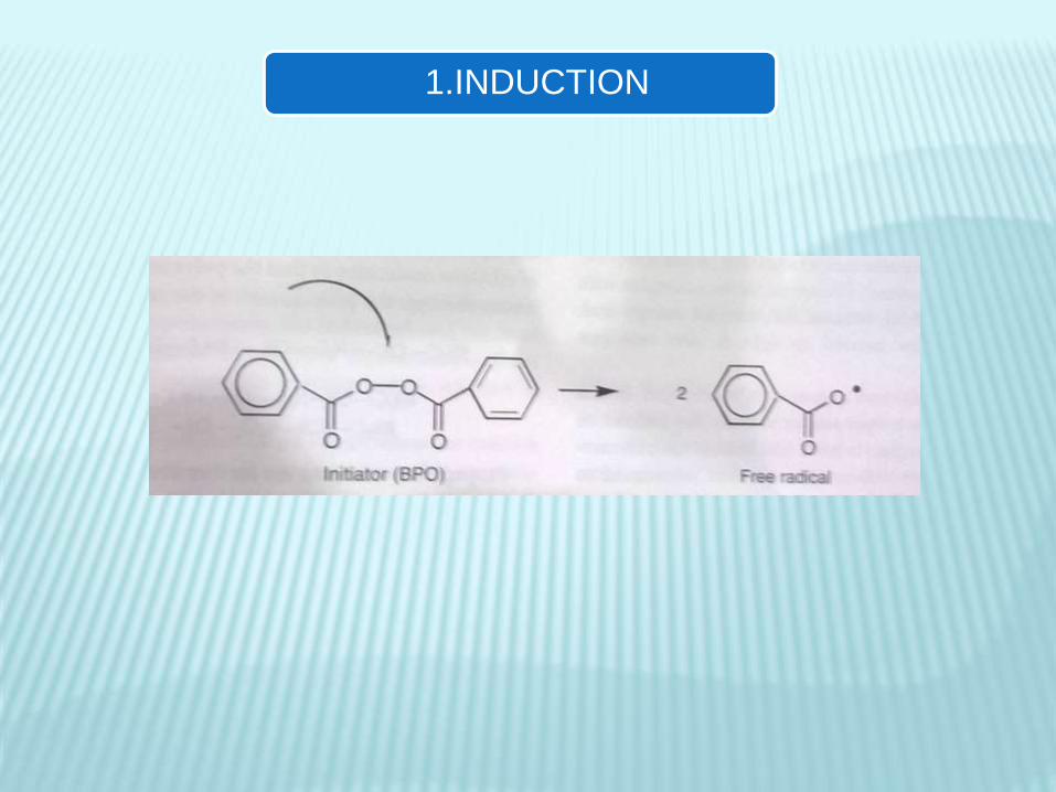
1.INDUCTION
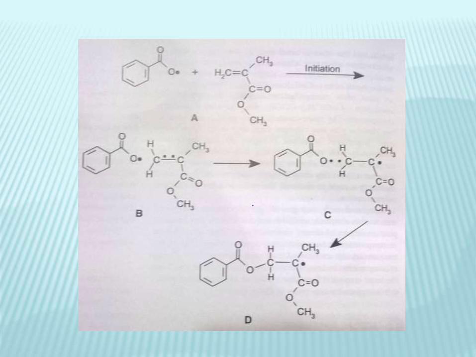

2.PROPAGATION

3.CHAIN TRANSFER

4.TERMINATION

ADVANTAGES DISADVANTAGES
Convenience and simplicity Mixing causes air entrapment
leading to porosity which might
weaken the material and
increase staining
Long term storage stability Aromatic amine accelerators
Oxidize and turn yellow with
time i.e color instability
Manipulation of working/Setting
time by varying proportions
Difficult to mix evenly
Degree of cure equal through
out if mixed properly
Marginal stress build up during
curing is much lower than for
photocured due to slower cross
linking


LIGHT CURING/PHOTOCHEMICALLY ACTIVATED
RESIN
UV LIGHT CURED VISIBLE LIGHT CURED
UV LIGHT CURED:
USED BEFORE.
LIMITED PENETRATION OF LIGHT INTO RESIN.
LACK OF PENETRATION THROUGH TOOTH STRUCTURE
CAUSED DAMAGE TO RETINA
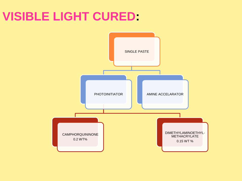
VISIBLE LIGHT CURED:
SINGLE PASTE
PHOTOINITIATOR
CAMPHORQUININONE
0.2 WT%
DIMETHYLAMINOETHYL-METHACRYLATE
0.15 WT %
AMINE ACCELARATOR

POLYMERIZATIO
N
Exposure to light
(Wavelength 400-500nm)
Excites photosensitizer
Photosensitizerreacts with
Amine
Free radicals formed
Addition polymerization
starts


Advantages and DIsadvantages

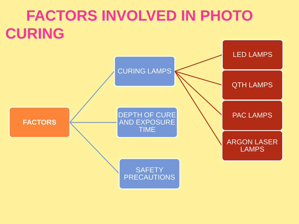
FACTORS INVOLVED IN PHOTO
CURING
FACTORS
CURING LAMPS
LED LAMPS
QTH LAMPS
PAC LAMPS
ARGON LASER LAMPS
DEPTH OF CURE AND EXPOSURE
TIME
SAFETY PRECAUTIONS

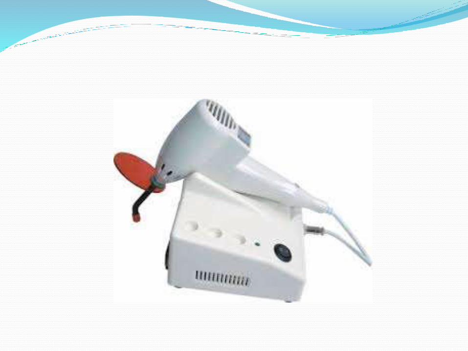
•Hand held devices which contain the light source and have a rigid light guide made
up of fused optical fibers.
•The most widely used light source is QUARTZ bulb with a Tungsten filament in a
Halogen enviroment.
•Four types of lamps are used:
1.Light emitting Diode lamps (LED)
2.Quartz-tungsten-halogen (QTH) lamps
3.Plasma arc curing lamps (PAC)
4.Argon laser lamps

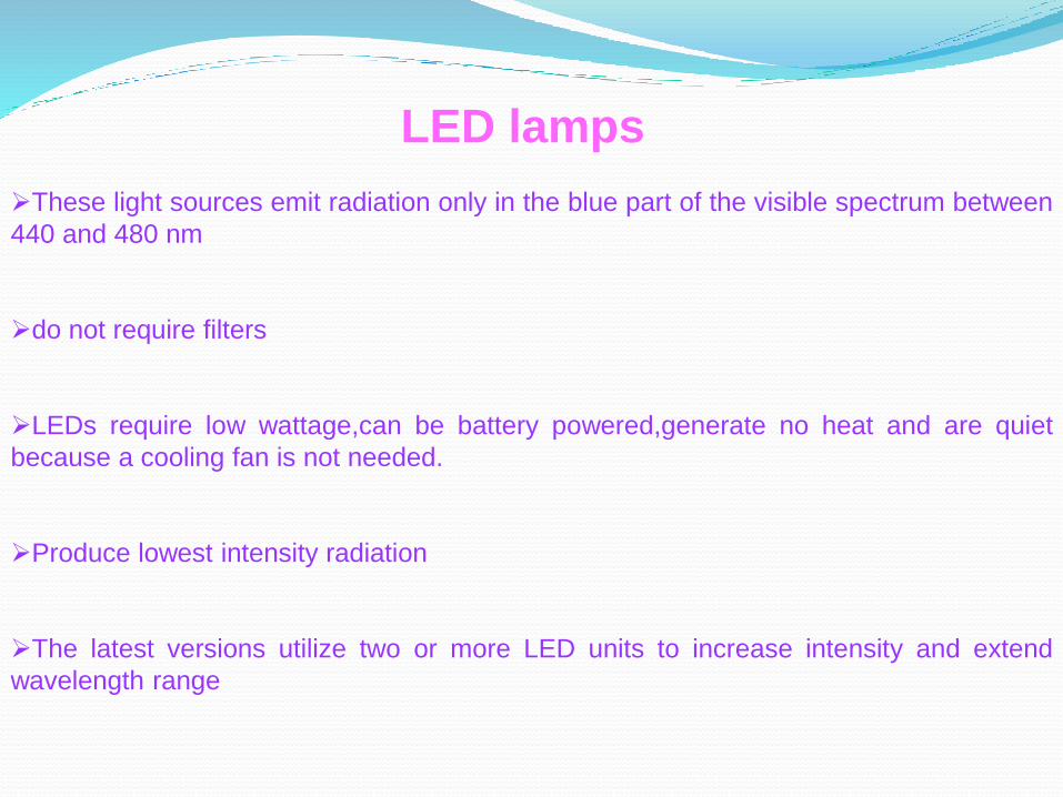
LED lamps
These light sources emit radiation only in the blue part of the visible spectrum between
440 and 480 nm
do not require filters
LEDs require low wattage,can be battery powered,generate no heat and are quiet
because a cooling fan is not needed.
Produce lowest intensity radiation
The latest versions utilize two or more LED units to increase intensity and extend
wavelength range


Quartz-tungsten-Halogen (QTH) lamps
QTH lamps have a quartz bulb with a tungsten filament that irradiates both UV and
white light
Must be filtered to remove heat and all wavelengths except those in the violet blue
range (~450 to 500 nm)
Intensity diminishes with use.
Plasma arc curing (PAC) lamps
Use ionized xenon gas to produce plasma
High intensity white light is filtered to remove heat
Blue light is then emitted (400-500nm)


Argon lamps
Highest intensity
Emit at a single wavlength
Emit wavelength of 490nm.

DEPTH OF CURE AND EXPOSURE TIME
•Amount of photons absorbed by initiator depends on
Wavelength
Light intensity
Exposure time
•For maximum curing radiant energy influx should be 16,000 mJ/cm2
• Light absorbtion and scattering in resin composites reduce the degree of
conversion and depth of penetration so exposure time should be increased.
•Curing depth should be kept 2-3mm
•Exposure time depends on the intensity of curing units.
•Higher the intensity lesser will be the exposure time


•Light attenuation varies for different composites so manufacturers instructions
should be followed.
To maximize the degree of polymerization and clinical durablity clinician should
adjust curing time and curing technique to intensity of light source.
Light is also absorbed and scattered as it passes through tooth structure especially dentin ,causing incomplete curing so in critical areas like proximal box so here the exposure time must be increased to compensate for reduction in light intensity
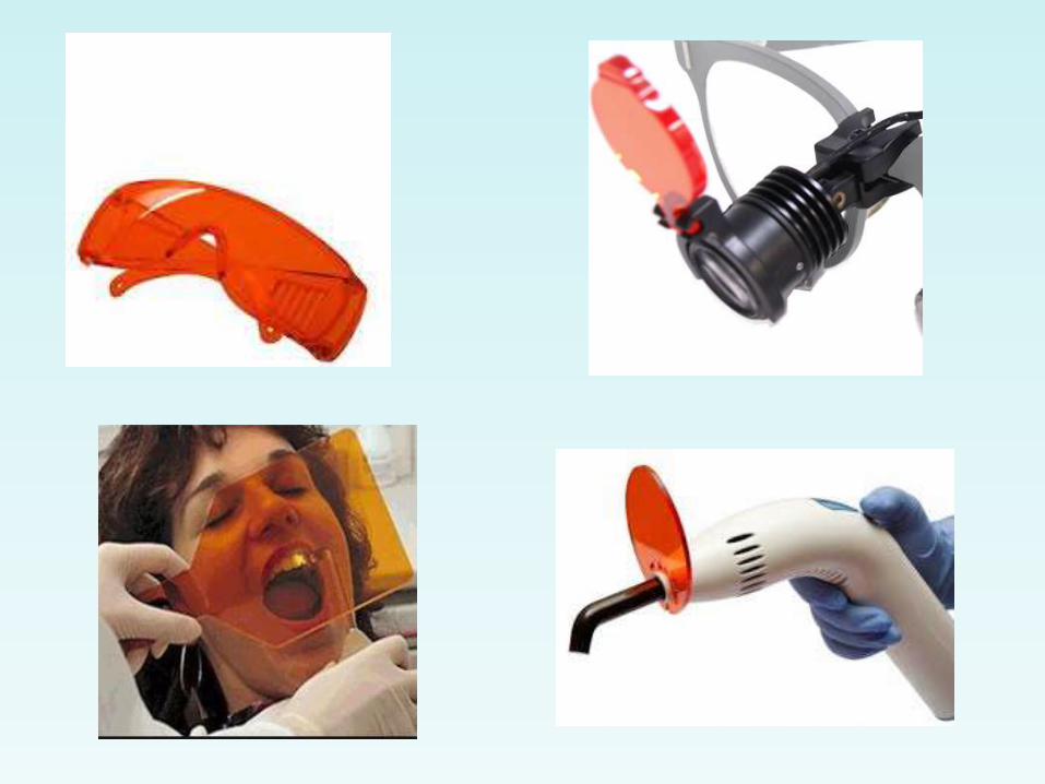
•Light emiitted by curing units can cause retinal damage.
•Never look directly into light tip and reflected light for longer periods
•Wear protective eye glasses and shields that filter light both for operator and
patient.

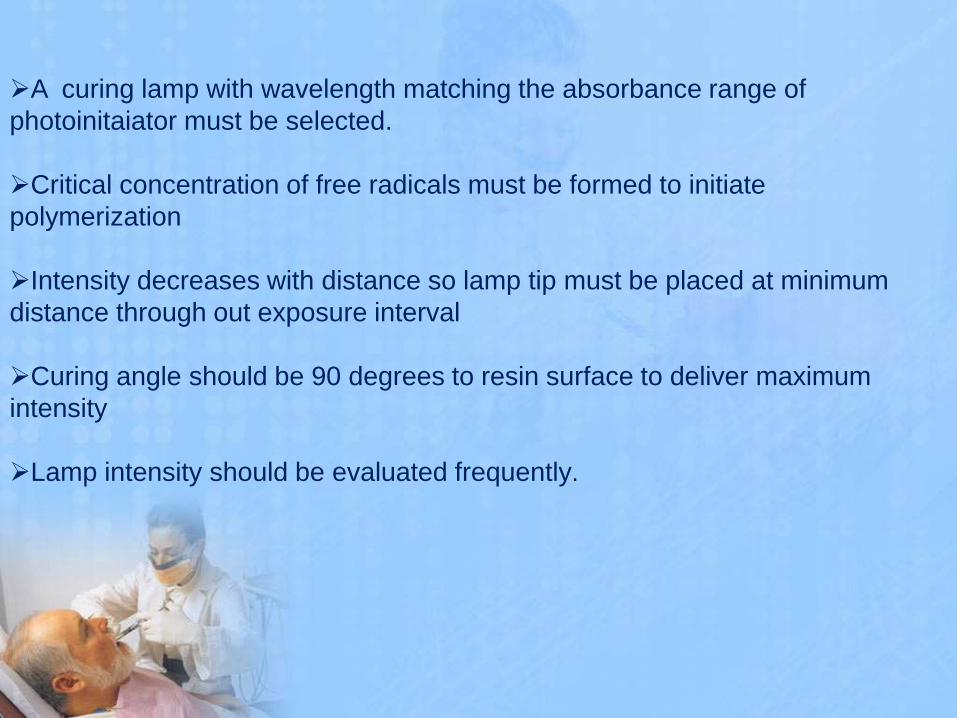
A curing lamp with wavelength matching the absorbance range of
photoinitaiator must be selected.
Critical concentration of free radicals must be formed to initiate
polymerization
Intensity decreases with distance so lamp tip must be placed at minimum
distance through out exposure interval
Curing angle should be 90 degrees to resin surface to deliver maximum
intensity
Lamp intensity should be evaluated frequently.
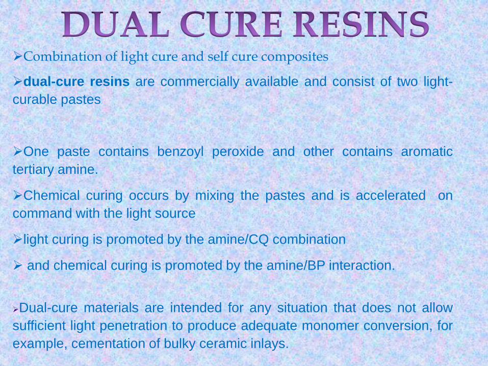
Combination of light cure and self cure composites
dual-cure resins are commercially available and consist of two light-
curable pastes
One paste contains benzoyl peroxide and other contains aromatic
tertiary amine.
Chemical curing occurs by mixing the pastes and is accelerated on
command with the light source
light curing is promoted by the amine/CQ combination
and chemical curing is promoted by the amine/BP interaction.
Dual-cure materials are intended for any situation that does not allow
sufficient light penetration to produce adequate monomer conversion, for
example, cementation of bulky ceramic inlays.

ADVANTAGE:
•Complete curing throughout is the advantage
DISADVANTAGE:
•Porosity
•Colour instability

CLASSIFICATION

CLASSIFICATION OF COMPOSITES:
I. Classification given by Skinner:
Traditional or conventional composites
8-12 .m
Small particle filled composites
1-5 . m
Microfilled composites
0-04 –0.9 . m.
Hybrid composites
0.6-1 . m
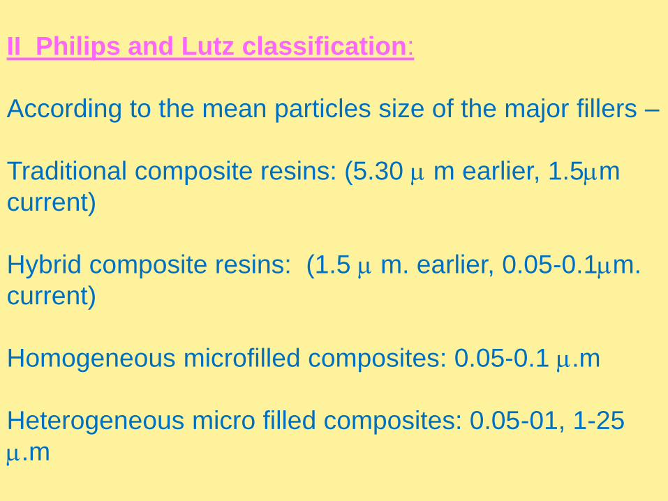
II Philips and Lutz classification:
According to the mean particles size of the major fillers –
Traditional composite resins: (5.30 m earlier, 1.5m
current)
Hybrid composite resins: (1.5 m. earlier, 0.05-0.1m.
current)
Homogeneous microfilled composites: 0.05-0.1 .m
Heterogeneous micro filled composites: 0.05-01, 1-25
.m

III Classifications based on inorganic loading:
a. Heavy filled materials – 75% of inorganic loading by wt
b .Lightly filled material –66% of inorganic loading by wt.

IV. Based on method of curing
1. Chemical cured
2. Light cured
3. Heat cured
4. Dual cured
V Classification based on area used
Anterior composites
Posterior composites

VI.GENERATIONS OF COMPOSITE RESTORATION
(Marzouk)
A. First Generation composites
•Consist of macro-ceramic reinforcing phase.
•Has good mechanical properties.
•Highest surface roughness
B. Second Generation composites
•Consists of colloidal and micro-ceramic silica.
•Low strength
•Unfavourable coefficient of thermal expansion
•Wear resistance better than first generation
•Best surface texture.

C. Third Generation composites
•Hybrid composite[combination of macro and micro
(colloidal) ceramics]
•Good surface smoothness and reasonable strength
D. Fourth Generation composites
•Hybrid composite (heat-cured, irregularly shaped, highly
reinforced composite macro-particles with micro (colloidal)
ceramics].
•Comparatively better surface characteristics and
mechanical properties

E. Fifth Generation composites:
•Hybrid composite (heat-cured, spherical, highly reinforced composite macro. particles with micro (colloidal) ceramics].•Improved workability•Surface texture and wear is similar to second generation composites•Physical and mechanical properties similar to fourth generation composites
F. Sixth Generation composites:
•Hybrid composite [agglomerates of sintered •micro (colloidal) ceramics and micro-ceramics]•Highest percentage of reinforcing particles•Best mechanical properties•Wear and surface texture similar to fourth generation•Least polymerization shrinkage
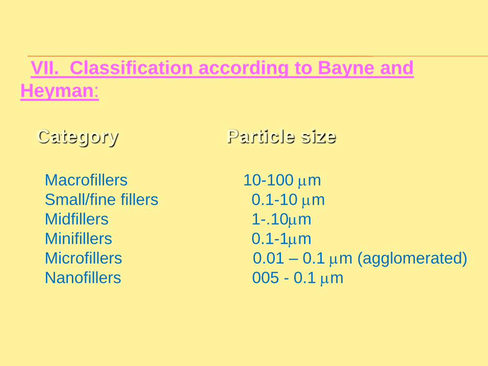
VII. Classification according to Bayne and
Heyman:
Category Particle size
Macrofillers 10-100 m
Small/fine fillers 0.1-10 m
Midfillers 1-.10m
Minifillers 0.1-1m
Microfillers 0.01 – 0.1 m (agglomerated)
Nanofillers 005 - 0.1 m

Composite types
Traditional Composites
Conventional or macrofilled composites.
The traditional composites have comparatively large filler
particles.
This category was developed during the 1970
The most commonly used filler for these materials is finely
ground amorphous silica and quartz.
Although the average size is 8 to 12 μm, particles as large
as 50 μm may also be present.
Filler loading generally is 70 to 80 wt% or 60 to 70 vol%
Advantage
High stength
Disadvantage
rough surface
Poor wear resistance
Poor marginal integrity
Finishing produces a roughened surface
Discoloration due to rough textured surface to retain stain.


Small-Particle-Filled Composites
To improve surface smoothness and retain or improve the
physical and mechanical properties of traditional composites
inorganic fillers are ground to a size range of 0.1 to 10μm.
•Fillers were made by grinding quartz to small particle size smaller
than traditional.
Small-particle-filled (SPF) composites generally contain more
inorganic filler (80 to 90 wt% and 65 to 77 vol%) than traditional
composites.
High strength and high hardness
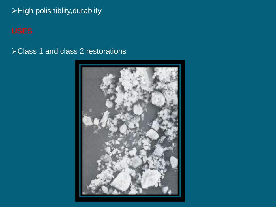
High polishiblity,durablity.
USES
Class 1 and class 2 restorations
Microfilled Composites
Agglomerates of 0.01 to 0.1 um inorganic colloidal silica
The problems of surface roughening and low translucency
associated with traditional and small particle composites can be
over come through the use of colloidal silica particles as the
inorganic filler.
1.Homogenous
2.Heterogenous

Homogenous
Silica compound
SiCL4
Pyrolyticprecipitation
Amorphous silica0.04 um or 40nmHighly polishable

Small size
Large surface area +
Agglomeration and long chains
Increased monomer viscocity
2 % wt produces a stiff paste
Decrease filler
loading
Inferior mech.
properties
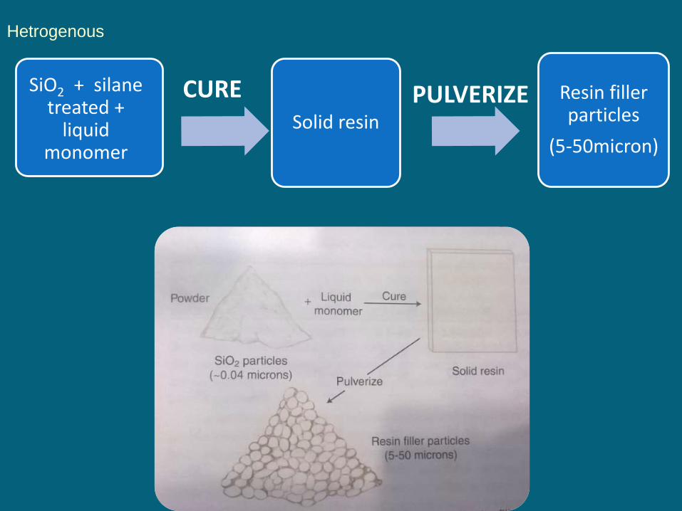
Hetrogenous
SiO2 + silanetreated +
liquid monomer
Solid resin
Resin filler particles
(5-50micron)
CURE PULVERIZE

PRECURED RESIN FILLER + MONOMER + SILANE TREATED COLLOIDAL SILICA = HETROGENOUS COMPOSITE
•Inorganic filler loading is increased by50 %
ADVANTAGES
•High polishiblity•Less shrinkage
DISADVANTAGES:•Weak bonding between precured resinparticles and matrix•Increased wear•Decreased mechanical properties•Not suitable for stress bearing areas

They should be finished with diamond burs rather than carbide burs as they are very much prone to chipping
•Material of choice for smooth surface lesions like class 3 and class 5
SUBTYPES:
1. Splintered prepolymerized particle2. Spherical prepolymerized particle3. Agglomerated prepolymerized particle

This category of composite materials was developed in an
effort to obtain even better surface smoothness than that
provided by the large particle composites, while still
maintaining the desirable properties.
Hybrid composites contain two kinds of filler particles:
Most modern hybrid fillers consist of:
1.Colloidal silica
2.Ground particles of glasses containing heavy metals.
Constituting a filler content of approximately 75 to 80 wt%
Hybrid Composites
The glasses have an average particle size of about 0.4 to 1.0
μm.
Colloidal silica represents 10 to 20 wt% of the total filler
content.
The mechanical properties inferior to those SPF composites
Surface smoothness + good strength Anterior
restorations,including Class IV sites.
• High stress areas where aesthetics dominates

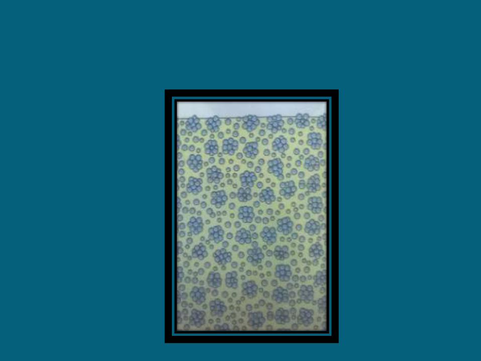
• Nanofillers are the filler particles.
• These particles are extremely small (0.005-0.01 nm) and virtually invisible
• Their particle size is below range of wavelength of light and thus they do not absorb or scatter visible light
• Aggregates are silane treated
NANOFILLED COMPOSITES
• Additionally the extremely small size of nanofillers allow the particles to fit into spaces between other particles in composite and effectively increase the overall filler level.
• Nanofiller permit overall filler level of 80 wt% that significantly reduce the effect of polymerisation shrinkage and dramatically improves physical properties
• Commercially available nanocomposites:Filtek supreme plus Tetric N Ceram
NANOHYBRIDS
•Like conventional hybrids in range of size of nano fillers
•Mechanical properties like conventional hybrids
•Aesthetics and polishiblity like microfilled composites
•They can be used for both anterior and posterior restorations
•Stronger than nanocomposites


FLOWABLE COMPOSITES
A modifications of the SPF and hybrid composites.
The reduced filler makes them more susceptible to wear, but
improves the clinician’s ability to form a well adapted cavity
base or liner, especially in Class II posterior preparations and
other situations in which access is difficult.
Decrease filler
loading
Decreased viscosity
Easy to flow
Adapt into cavity
Diifcultaccessiblityposterior
areas
Called dental caulk,as it can flow into small crevices along restoration margins

USES: Sealing gingival floor of the proximal box of Class II restorations. Class V cavities. Small Class III cavities. First increment of all deep restorations to prevent voids and porosities and
to get good seal. Small Class I cavities frequently referred to as ‘Preventive Resin
Restorations’. Blocking out cavity undercuts during inlay, onlay and crown preparations
ADVANTAGES:• Decreased microleakage• Increased marginal adaptation
DISADVANTAGE:• High curing shrinkage• Decreased mechanical properties• Cannot be used in large restorations because of decrease wear resistance

CONDENSABLE COMPOSITES
•Because of the highly plastic, paste like consistency in the precured state,
composites cannot be packed vertically into a cavity in such a way that the
material flows laterally as well as vertically to ensure intimate contact with
the cavity walls.
•This can be explained in terms of class 2 cavity
•Compared with amalgam, the technique of composite placement is far
more time consuming and demanding.
• A solution to this problem is offered by resin composites with filler
characteristics that increase the strength and stiffness of the uncured
material and that provide a consistency similar to that of lathe-cut
amalgams.

•Elongated, fibrous, filler particles of about 100 μm in length
•RoughTextured surfaces and branched geometry tend to inter lock and
resist flow.
• This causes the uncured resin to be stiff and resistant to slumping,yetmoldable under the force of amalgam Condensing instruments (“Plugger”)

PROPERTIES
1.WORKING TIME AND SETTING TIME
Chemical cured composites:
Setting time:3-5 minutes
Working time:from start of mix till temperature
begins to rise

Light cured composites:
Curing is considered on demand
Composite may appear to be fully hard and cured after curing by light source,but curing reaction continues for 24 hours.
Degree of conversion is 75 %
Premature polymerization can occur with 60-90 seconds of exposure to the ambient light.

Degree of conversion/Degree of cure /Degree of
monomer to polymer conversion
•Percentage of carbon carbon double bonds
converted to single bonds during curing to form a
polymer resin
•Higher the DC greater is the strength,wear and
other propertiesA conversion of 50 % Bis-GMA means 50 % of polymer have
been polymerized
BUT
This does not mean remaining 40-50 % monomer is left in
resin because one of the two methacrylates group of Bis-
GMA may form covalent bonds with polymer forming a
pendant group

Conversion of monomer to polymer depends on
several factors like:
1.Resin composition
2.Transmission of light through material
3.Concentration of Sensitizer,initiator and
inhibitor
4.Lamp intensity
5.Absorbtion through composite
6.Scattering through composite

2.POLYMERIZATION SHRINKAGE
The normal range of curing shrinkage is 1.5
to 4 vol % 24 hours after curing
Composites with a high filler loading shrink
less
Chemically activated have a slow curing than
light cure resins which allows the shrinkage
stresses to relax
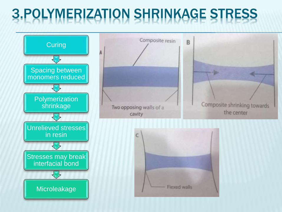
3.POLYMERIZATION SHRINKAGE STRESS
Curing
Spacing between monomers reduced
Polymerization shrinkage
Unrelieved stresses in resin
Stresses may break interfacial bond
Microleakage
The polymerization shrinkage and stress
affected by:
1.Total vol of composite
2.Type of composite
3.polymerization speed
4.C-Factor

REDUCTION OF RESIDUAL STRESSES
The internal pores in chemically cured resins
act to relax residual stresses that build up
during polymerization.
The slower curing rate of chemical activation
allows a portion of the shrinkage to be
compensated by internal flow among
developing polymer chains before formation of
extensive crosslinking

After the gel point ,stresses cannot be
relieved but instead continue to increase and
concentrate within the resin and the tooth
structure adjacent to the bonded interfaces.
Approaches to overcome the problem of
stress concentration:
1)reduction in volume contracton by altering the chemistry and or composition of the resin system
2) clinical techniques designed to offset the effects of polymerization shrinkage

1.Incremental build up and cavity configuration
CONFIGURATION FACTOR (C-Factor)
• Is the ratio between the bonded surface areas of a resin based composite restoration to the non-bonded or free surface area
• Bonded surface/non bonded surface = C factor

• Residual polymerization stresses increases directly with this ratio.
• During curing, shrinkage leaves the bonded cavity surfaces in a state of stresses
• The non bonded ,free surfaces release some of the stresses by contracting inwards towards the bulk of material
• A layering technique in which the restoration,is build up in increments ,curing one layer at a time efficiently reduces polymerization stresses by minimizing the c factor
• The thinner layer lower the bonded surface and maximize the non bonded surface area.
ADVANTAGE
• This technique overcomes the limited depth cure and residual stress concentrations
DISADVANTAGE
• Adds to time and difficulty in placing restoration


2.Soft start,ramp curing and delayed curing
Photo-polymerization stress buildup
inspired by chemical initiation by
providing an initial low rate of
polymerization thereby extending the
available time for stress relaxation before
reaching gel point .

In this technique curing begins with a low
intensity and finishes with high intensity
SOFT START
SLOW POLYMERIZATION
INITIALLY
INCREASED STRESS
RELAXATION
GELATION POINT REACHED
INCREASE INTENSITY TO
MAXIMUM
Ramped curing and delayed curing
Variations of soft start
RAMPING CURING:
The intensity is gradually increased or ramped up during exposure.
Consist of either stepwise, linear or exponential modes

Delayed curing:
LOW INTENSITY
INCOMPLETE CURING
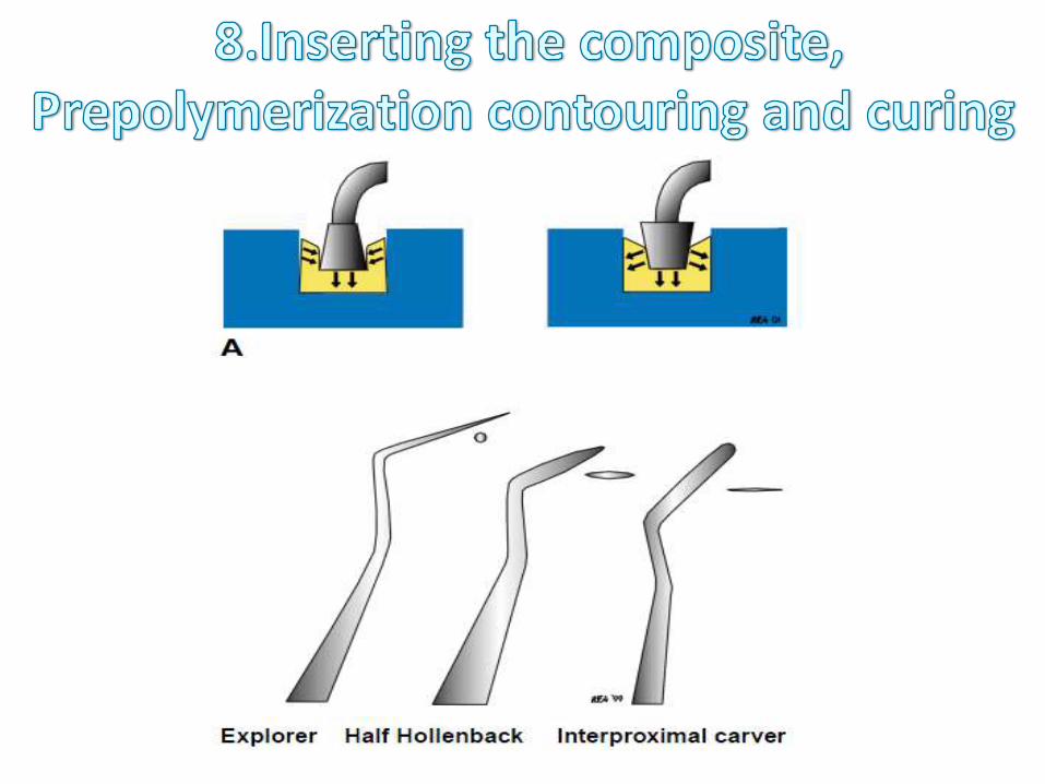
CONTOUR AND
SCULPTING RESIN
SECOND EXPOSURE FOR FINAL
CURE
Delay allows substantial stress relaxation to take place.
The longer the time period available for relaxation the lower the residual stresses.
Delayed and exponential ramp curing appear to provide the greater reduction in curing stress.
Intensity of the curing lamps must be considered in such situations as exposure time and curing are related to the intensity of the lamps.

4.COEFFICIENT OF THERMAL EXPANSION
Linear coefficient of thermal expansion of composite ranges between 25-30 x 10-6 /℃ and 55-68 x 10-6 /℃
Large differences between CTE of tooth and composite causes expansion and contraction resulting in stress
Filler loading is the only way to reduce the CTE.

5.WATER SORPTION
Water sorption may occur when:
1.Material may have a high solublity rate.
2.Resin may contain voids
3.Hydrolytic breakdown of the bonds between fillers and resin
Water sorption can decrement the longetivity of the restorations.
6.SOLUBLITY
Inadequate light intensity and duration especially in deeper areas causes incomplete polymerization and increased solublity.
ADA specifies solublity should be less than or equal to 7.5 µg/mm
Higher values lead to reduce wear and abrasion resistance.
7.RADIO OPACITY
Radio opacity is to check the integrity of resin
Radio opacity can be provided by glass
ceramics with heavy metals like Ba,Sr and Zr
Not chemically inert

8.COLOUR STABILITY
Esthetics is the major factor for use of
composites
Discolouration can be;
1.Marginal
2.Surface
3.Bulk
1. Marginal discolouration
May occur due to:
1.Improper adaptation of material to cavity
margin
2.Breakage of interfacial bonds between resin
and cavity
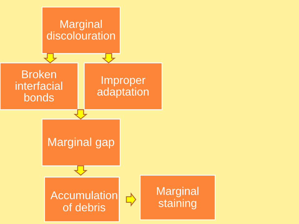
Marginal discolouration
Improper adaptation
Broken interfacial
bonds
Marginal staining
Accumulation of debris
Marginal gap

2.SURFACE DISCOLORATION
Related to surface roughness of the composite.
Seen in composites with larger filler sizes.
Debris gets entrapped between the spaces and
cannot be removed by routine brushing.
Dark pitted discolouration may be seen due to
exposure of air void when composite wears away.

3. Bulk discolouration
Seen in chemically activated resin mainly
Chemical degradation of components and
absorbtion of fluids from oral enviroment

Composites show loss of surface contour of composite
restorations in the mouth
Abrasive wear from chewing and tooth brushing
Erosive wear from degradation of the composite in the oral
environment
Wear of posterior composite restorations is observed at the
contact area,where stresses are the highest.
Interproximal wear has also been observed.
9.WEAR RATES
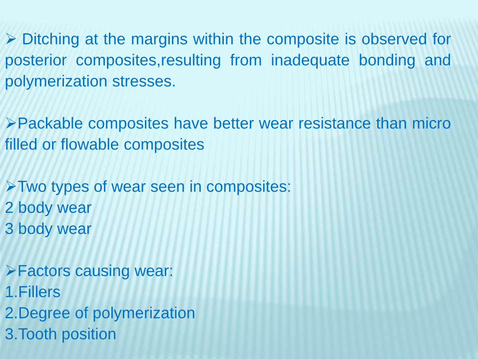
Ditching at the margins within the composite is observed for
posterior composites,resulting from inadequate bonding and
polymerization stresses.
Packable composites have better wear resistance than micro
filled or flowable composites
Two types of wear seen in composites:
2 body wear
3 body wear
Factors causing wear:
1.Fillers
2.Degree of polymerization
3.Tooth position

Picture from phillips pg
284

BIOCOMPATIBLITY

BIOCOMPATIBLITY
It is usually related to the effects on pulp from two aspects:
1. Inherent chemical toxicity of material
2. The marginal leakage of the fluids
•Pulp can be affected if chemicals leach out from the composites.
•Inadequately cured composites at floor of cavity act as a
reservoir of diffusable components that can induce long term
pulpal inflammation.
•This is for concern in case of light cure.
•If clinician attempts to cure a thick segment or inadequate
exposure the uncured material can leach out constituents
adjacent to the pulp.
•Adequately polymerized resins leach out in very small amounts
which cannot cause toxicity.
Inherent chemical toxicity of material
• The shrinkage of composite during polymerization and the subsequent marginal leakage is a well known phenomenon
• The marginal leakage might allow bacterial growth and the microorganisms may cause secondary caries or pulpalreaction.
• Therefore ,the restorative procedure must be designed to minimize polymerization shrinkage and marginal leakage
The marginal leakage of the fluids

• Bisphenol A (BPA), a precursor of BiSGMA has been
shown to be a xenoestrogen ,or a compound found
in environment that mimics the effects of estrogen
by having affinity for estrogen receptors
• BPA has been shown to cause reproductive
anomalies especially in development stages of fetal
wildlife
• Controversy surrounds this issue because it is unclear
how much BPA or BPA-DM is released to the oral cavity
and what dosage is enough to affect human health.

•Gic liners are applied as pulp protection in deep cavities
•Zincoxide eugenol is contraindiated as it interferes with
polymerization

Technique

1.Preparation of operating site
2.Shade selection
3.Cavity preparation
4.Isolation
5.Pulp protection
6.Adhesion
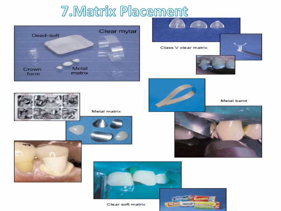
7.Matrix placement
8.Insertion,prepolymerization contouring and
curing
9.Finishing
10.Polishing

1.Calculus removal with proper instruments
2.Cleaning operting site with pumice slurry
Create a site more receptive for bonding
Prophy paste containing flavouring agent,glycerine
or flouride act as contaminants and conflict with
acid etch technique.
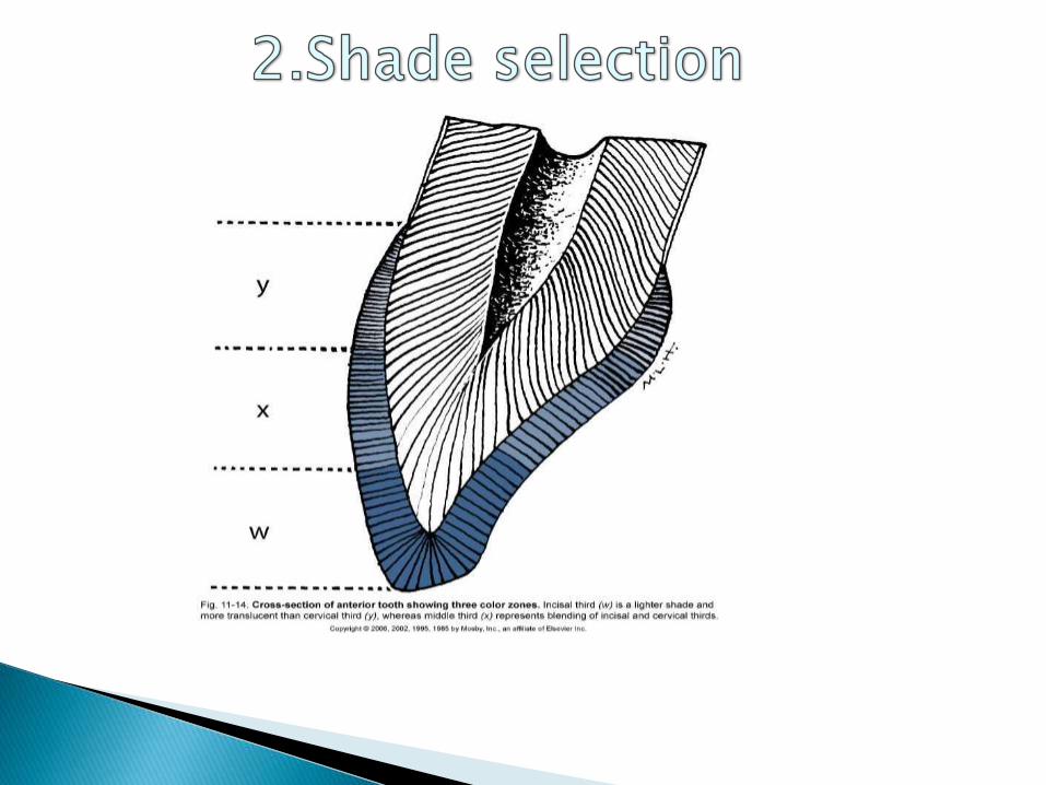

Shade of the tooth should be selected before isolation
Shade should be selected without prolonged drying the tooth
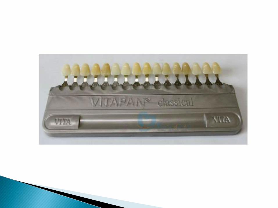
Composite materials are available in:
Enamel shadesDentin shadesTranslucent shadesOpaque shades
Good lighting should be present for proper color selection

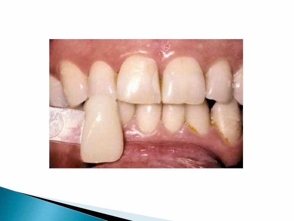
1.Operator should hold shade tab near the tooth to determine natural colour.
2.Shade tab should be partially covered with operators thumb or patients lip – natural effect of shadows
3.The selection of shade should be done in natural light
4.The selection should be made rapidly
5.Final shade can be verified by patient with a mirror
6.Bleaching if done should be done before any restoration placement
The shade selected should be placed directly on the
tooth close to area to be restored and cured
PROCEDURE

Objectives in tooth preparation:
Extent is determined by size, shape, and location of defect
Remove all Caries, any fault, defective, old friable tooth structure.
Removal of discolored tooth structure as required for esthetics.
Create prepared enamel margin of 90° or greater by giving bevel wherever required.
Create 90° cavosurface on root surfaces

Outline form
Extend from periphery to sound tooth structure
Preparation should be done in most conservative way as possible
Retention form
Micromechanical retention by etching of enamel and dentin.
Dentinal retention groove
Enamel beveling

Beveling provides increased surface area of etching
Increased retentionDecreased microleakage
Gradual transition between composite and tooth
Bevels of 45 degrees should be given:1-2mm wide facially0.5mm other areas
Bevels should be prepared with medium grit diamond burs
Bevels should be avoided in:Class 1 restorationsClass 2 restorationsCervical margins with thin enamel

Resistance form
Primarily by micromechanical bonding
May be improved by:
• Flat preparation floors
• Floors perpendicular to occlusal forces
• Boxlike forms

Cavity designs for composite cavity preparation
• Conventional
• Beveled conventional
• Modified
• Box shape
• Facial/lingual slot

CONVENTIONAL
Similar to that of cavity preparation for amalgam restoration.
A uniform depth of the cavity
90° cavosurface margin is required
INDICATIONS
1. Moderate to large class I and class II restorations
2. Preparation is located on root surfaces.
3. Old amalgam restoration being replaced
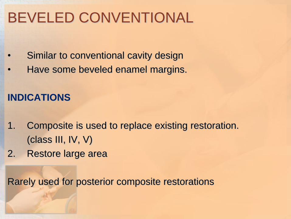
BEVELED CONVENTIONAL
• Similar to conventional cavity design
• Have some beveled enamel margins.
INDICATIONS
1. Composite is used to replace existing restoration.
(class III, IV, V)
2. Restore large area
Rarely used for posterior composite restorations
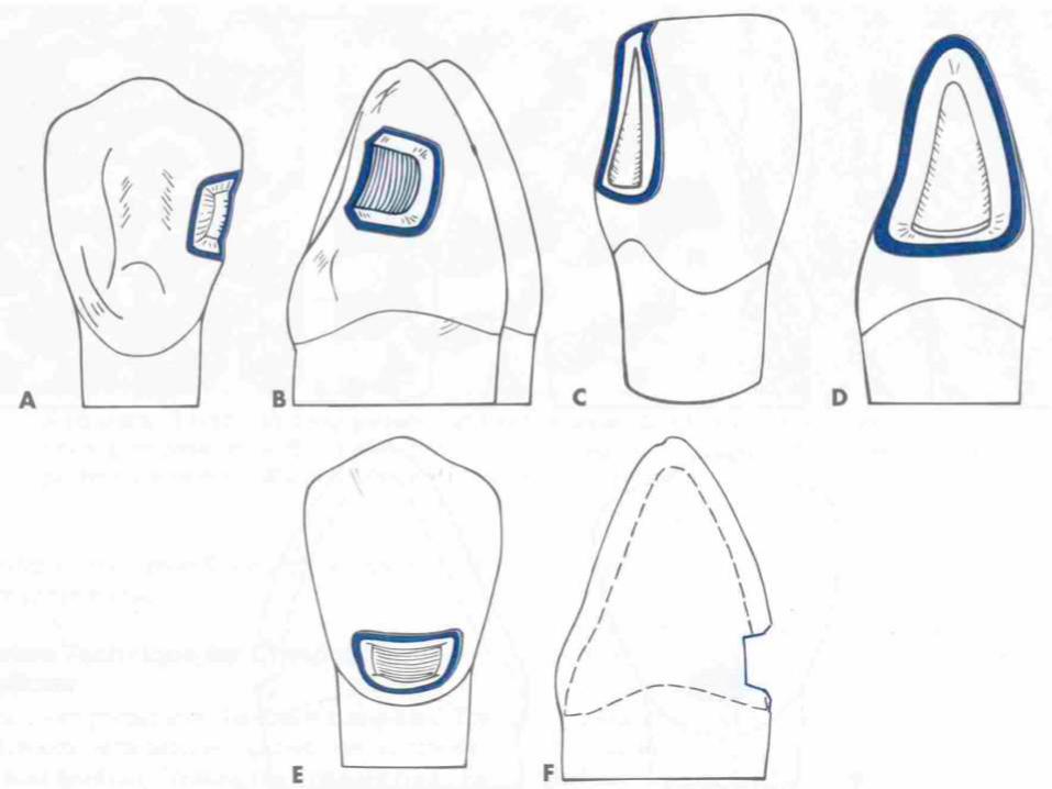

MODIFIED
• All parameters determined by extent of caries.
• Conserve tooth and obtain retention (MICRO MECHANICAL).
• No specified wall configuration.
• No Specified pulpal or axial depth.
• Scooped out appearance
INDICATIONS
• small,cavitated,carious lesion surrounded by enamel
• correcting enamel defects.

BOX ONLY
•When only Proximal surface is faulty and no lesion on occlusal surface
•Extent is determined by caries
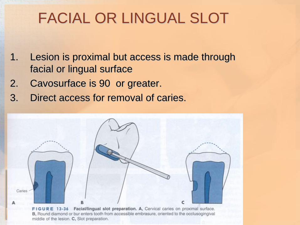
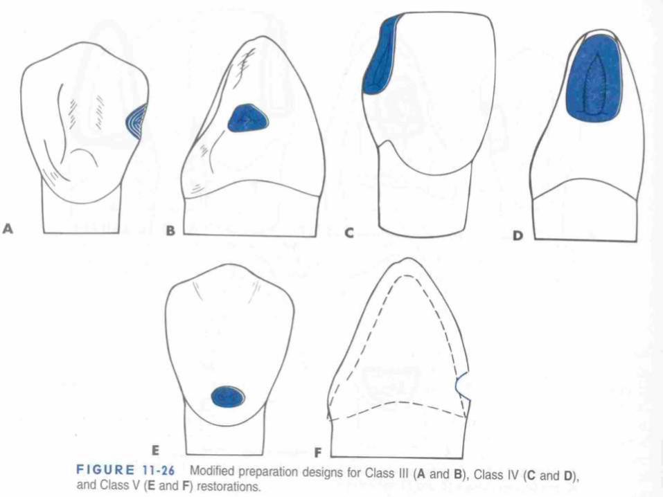
FACIAL OR LINGUAL SLOT
1. Lesion is proximal but access is made through
facial or lingual surface
2. Cavosurface is 90 or greater.
3. Direct access for removal of caries.

Isolation can be accomplished by rubber dams,cotton rolls
Retraction cords can be used for subgingival extensions
Contamination with saliva leads to decreased bond strength

Calcium hydroxide
Glass ionomer cement
Resin Modified Glass Ionomer
Zinc oxide eugenol is contraindicated
Acid
etchingBonding
agents

Acid may be grouped as:
Minerals (phosphoric acid,nitric acid)Organic (maleic acid,citric acid)Polymeric(e.g polyacrylic acid)
Most frequently used acid is 37% phosphoric acid
Available as: Gel or liquid form
Applied by brush or directly through syringe
15-20 seconds etching time
Primary teeth or young teeth with mind flourosis require longer etching time
Freshly cut enamel etches faster
Clinically the most important parameter of proper etched
tooth is presence of a frosty white appearance on tooth

Acid etch
Smear
layer
+
Enamel
removed
from
surface
1.Selective
dissolutio
n of
enamel
rods
2.Increase
d surface
area
Increased
surface
energy
Resin
penetrates
to
microporo
sites
Resin tags


Removes
hydroxy
appetite
layer
Microporous
collagen
network in
H20
Partially
open
dentinal
tubules

Clean tooth and isolate
Place mylar strip to
protect adjacent tooth
Place etchant liquid/gel
15-20 seconds
Wash for 10 sec
longer if gel used
Dry surface
Chalky white
appearance
Over drying must be avoided if dentin invloved as it may
result in collapse of collagen mesh which results in
forming a dense film and prevents bonding agent to
penetrate.

A thin layer of resin between conditioned dentin and resin matrix of resin composite restorative material.
Restorative resin are hydrophobic and tooth is are hydrophillicso bonding agent should have both parts.
The hydrophillic part bonds with calcium in hydroxyappatitecrystals or collagen and hydrophobic component bonds with restorative resin.

ETCHANT/CONDITIONER:selectively dissolves tooth structure to provide retention for restoration
PRIMERS:Bridge to connect tooth to adhesive
hydrophillic monomers in a solvent like alcohol,ethanol or water
Penetrate moist tooth structure especially dentin and collagen mesh and improve bond
EG:HEMA(2-hydroxylethyl methacrylate,4-MET(methacryloxyethyl trimelleticacid)
ADHESIVE:Hydrophobic monomers + small amount hydrophillic monomer

Used in combination with primers to form effective bond to tooth structure.
Adhesive bonds resin to primer
Primerpenetrates tooth and completes binding sequence
Eg: hydrophobic dimethacrylates like Bis-GMA with small amount of hydrophillic monomers like HEMA

Remove all debris and remove
excess water
Isolate tooth from saliva
contamintation
Saturate microbrush with
bonding agent
Apply with gentle rubbing
motion
Use gentle air pressure to
remove excess acetone and
water solvent
Cure for 20 seconds
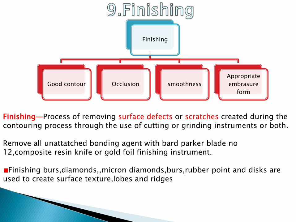
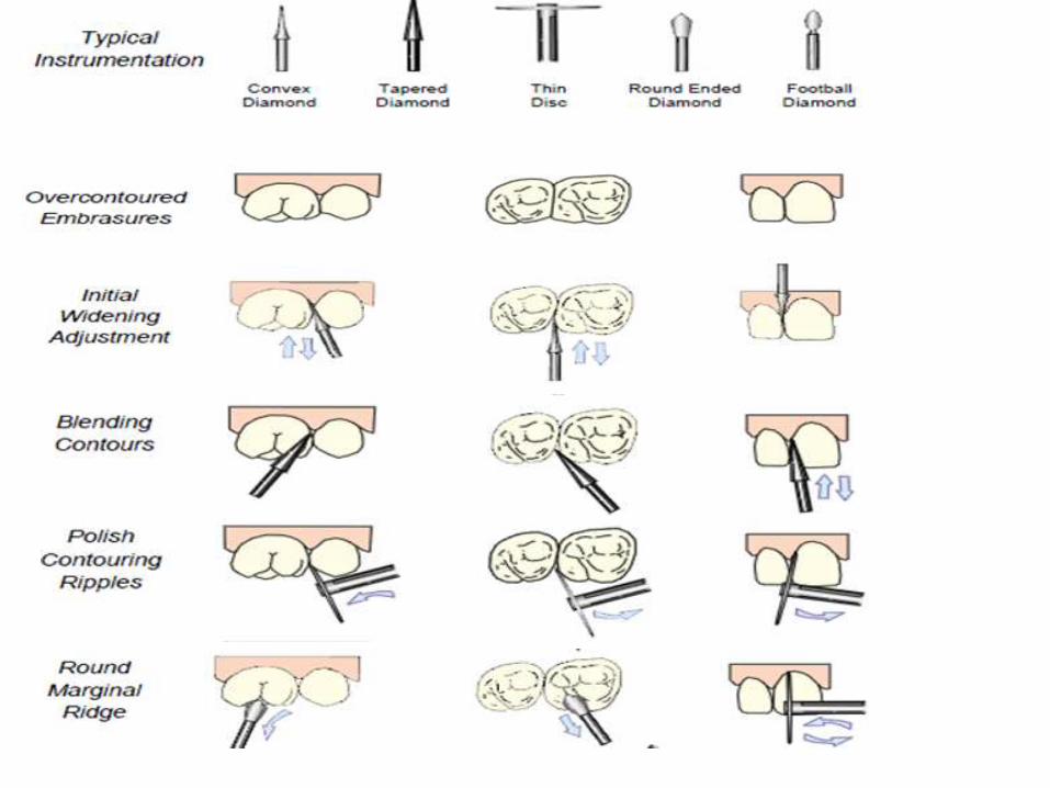
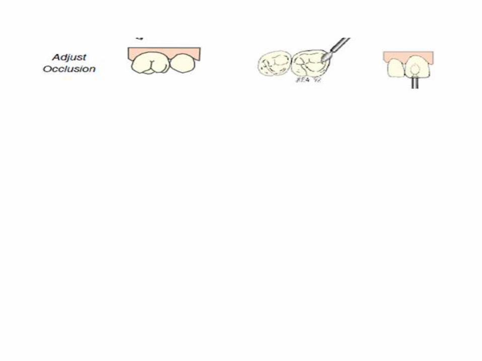
Finishing
Good contour Occlusion smoothness
Appropriate
embrasure
form
Finishing—Process of removing surface defects or scratches created during the contouring process through the use of cutting or grinding instruments or both.
Remove all unattatched bonding agent with bard parker blade no 12,composite resin knife or gold foil finishing instrument.
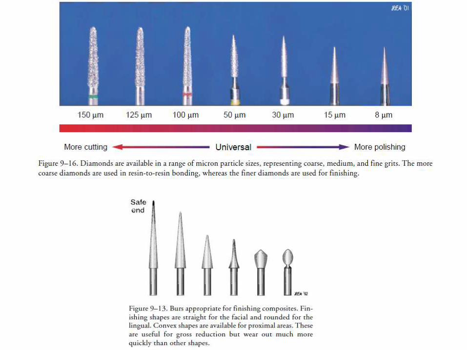
Finishing burs,diamonds,,micron diamonds,burs,rubber point and disks are used to create surface texture,lobes and ridges
Polishing cups and polishing paste are used for lusture
Metal or plastic finishing strips interproximally

Polishing—Process of providing luster or gloss on a material surface.
Removal of surface irregularites and achieving smoothest possible surface
Polishing can be DRY:superfine disksWET:Coarse disks
Aggressive use of disks may be avoided
Polishing paste can be used for 15-30 seconds using rubber cup moistened with water
Microfilled composites can be polished with disks
Small particle hybrids can be polished with fine diamonds,flexibledisks and very fine polishing paste

Dry polishing:should be resrved only for microfilledcomposites.The heat from the disks produces highly durable,smear layer of resin over microfill


Recent advancements
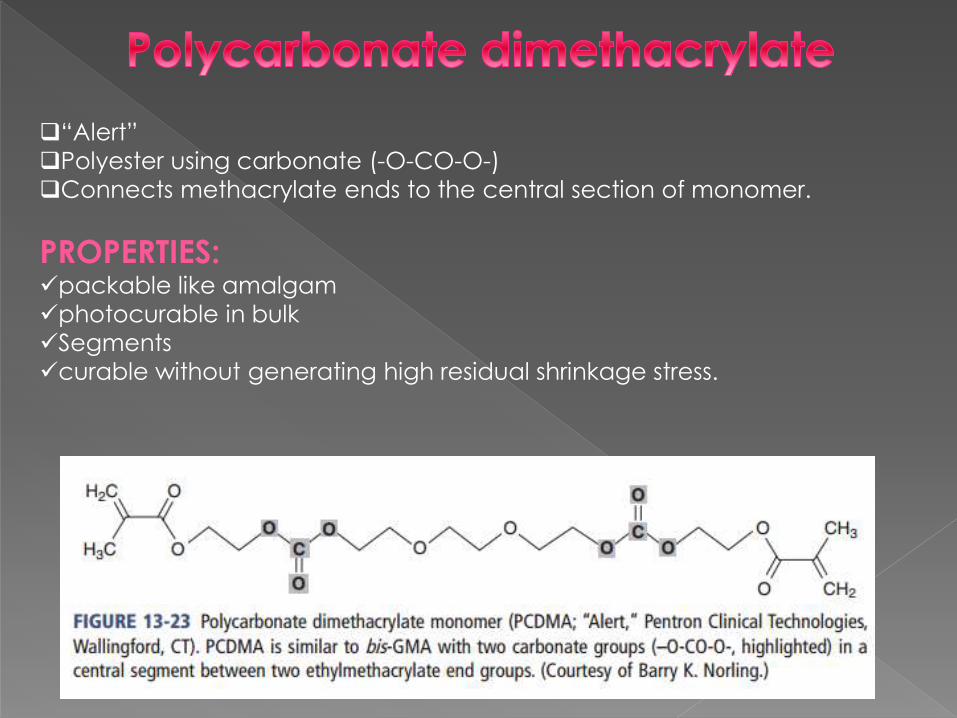
“Alert”
Polyester using carbonate (-O-CO-O-)
Connects methacrylate ends to the central section of monomer.
PROPERTIES:packable like amalgam
photocurable in bulk
Segments
curable without generating high residual shrinkage stress.

Kalore
High molecular weight
Long rigid central section
Flexible methacrylate end groups
PROPERTIES:Reduced curing shrinkage
Enhanced monomer to polymer conversion

“Venus Diamond
4,8-di(methacryloxy methylene)-tricyclodecane(TCDDMA)
Bulky space-filling dimethacrylate monomer
Bulky three-ring central group provides steric hindrance
Which holds the monomers apart
PROPERTIESslows the rate of polymerization
Steric
hinderence
Dimethacrylate with a Bulky, Space-Filling Central Group

Durance
Dimer dicarbamate dimethacrylate (DDCDMA)
Bulky central group:
6-carbon aliphatic ring
two long hydrocarbon side chains
Center section is connected to two methacrylate end groups via urethane
groups
PROPERTIES
Greater stress relaxation
reduced shrinkage.
reduced water absorption
High-Molecular-Weight Phase-Separating Dicarbamate
with Hydrophobic Side Chains

“Filtek LS”
chemistry based on epoxy, rather than acrylic functionality.
tetra-functional “silorane” monomers
ring-opening polymerization.
STRUCTURE:
Silorane chemistry utilizes a combination of epoxy functionality
three-unit ring with two carbons and an oxygen
combined with siloxane units
PROPERTIES:
Reduced polymerization shrinkage
Silorane” Ring-Opening Tetrafunctional Epoxy Siloxane

Organically Modified Ceramic Oligomers
Ormocer is an acronym for organically modified ceramics.
molecule-sized hybrid structures
inorganic-organic copolymers.
ORGANIC MONOMER
+
CENRAL CYCLIC POLYSILOXANE
High-mol-wt flexible
relatively low-viscosity
cross-linkable mol
PROPERTIES:
Reduced polymerization shrinkage,
abrasion resistance
low water sorption
very high biocompatibility
excellent esthetics.

Polyhedral Oligomeric Silsesquioxane (POSS)
12-sided silicate cages
silane and functionalized to copolymerize with other monomers.
molecule-sized hybrid organic-inorganic oligomeric compound
“Artiste Nano-Hybrid Composite” (Pentron Clinical, Wallingford, CT).
PROPERTIES:Highly polishable
Excellent polish retention,
Good mechanical properties
Good wear resistance.

Patient's demands for aesthetics, phenomenal developments in the resin and filler
technologies, advance in nanotechnology and clinical training in their use has made
composite resins a material of choice for direct restorative purposes. The wide range of
colours,shades,translucencies,opacities,flouroscence,tones,viscosity etc available with
present generations of composite resins have enabled clinicians to provide a restoration
that mimics natural tooth structure and optimizes function as well.
Further research is always an ongoing process to reduce or eliminate drawbacks of
composite resins