Palestine Polytechnic University Deanship of Graduate Studies and Scientific Research
Virtualization of Wireless LAN Infrastructures
Submitted by
Ghannam Aljabari
In partial fulfillment of requirements for the degree of Master in Informatics
April, 2012

The undersigned hereby certify that they have read and recommend to the Deanship of
Graduate Studies and Scientific Research at, Palestine Polytechnic University the accep
tance of a thesis entitled "Virtualization of Wi.reless LAN lnfra.strncl'ILres" submitted by
Ghannam Aljabari in partial fulfillment of the requirements for the degree of Master in
Informatics.
Graduate Advisory Committee
Prof. Dr. Evren Eren (Supervisor)
Dortmund University of Applied Sciences, Germany
Signature:£__?_ __ - _ Dr. Murad Abu Sbaih (Internal Examiner)
Palestine Polytechnic University, Palestine
< Sh SigIablIe:.. f= 1
Dr. Raed Zaghal (External Examiner)
Al-Quds University, Palestine
Thesis approved by
Prof. Dr. Karim Tahboub Dean of Graduate Studies and Scientific Research
Palestine Polytechnic University, Palestine
Signature.y ==
Date:
Date: I J , :9: • 2.ol L.
a r/a/2ova r i
Date: 2..l\ · J- · 2.6--f'l--

Abstract
In wired Ethernet networks (IEEE 802.3), a physical network interface can
be connected to different network segments or shared among multiple virtual
machines. In wireless LAN (IEEE 802.11) sharing a wireless network inter
face is recognized to be a difficult task. However, virtualization can solve
this problem. This thesis describes a software approach for hosting multiple
virtual wireless networks over a shared physical infrastructure by means of
open source virtualization techniques. This approach is called virtual WLAN,
which is an extension of wireless networking into virtualized environments.
The virtual WLAN has been implemented to get the functionality of multi
ple virtual wireless routers while using only a single physical wireless network
interface. Testing results have shown that a single wireless network inter
face can be shared among several virtual machines without compromising the
performance, isolation, or wireless LAN security mechanisms.
ii

Declaration
I declare that the master thesis entitled "Virlualization of Wireless LAN Infrastructures"
is my own original work, and hereby certify that unless stated, all work contained within this thesis is my own independent research and has not been subi:nitted for the award of
any other degree at any institution, except where due acknowledgement is made in the
text.
G hannam Alj abari
Signature: _ D)ale:
iii

Statement of Permission to Use
In presenting this thesis in partial fulfillment of the requirements for the master degree
in Informatics at Palestine Polytechnic University, I agree that the library shall make
it available to borrowers under rules of the library. Brief quotations from this thesis
are allowable without special permission, provided that accurate acknowledgement of the
source is made.
Permission for extensive quotation from, reproduction, or publication of this thesis may
be granted by my main supervisor, or in his absence, by the Dean of Graduate Studies
and Scientific Research when, in the opinion of either, the proposed use of the material is
for scholarly purposes. Any copying or use of the material in this thesis for financial gain
shall not be allowed without my written permission.
Ghannam Aljabari
p5[gall€.> D)ate:
iv

Dedication
For my family, who supported me each step of the way.
V

Acknowledgement
I would like to offer my gratitude to my supervisor, Prof. Dr. Evren Eren, for his efforts
with me throughout my thesis and without him this thesis would not have been completed
or written.
I would like to thank my committee chair, Dr. Radwan Tahboub, and my committee
members, Dr. Raed Zaghal and Dr. Murad Abu Sbaih for their valuable comments and
questions to improve this work.
In addition, many thanks go to Dr. Hashem Tamimi for his advice and guidance from
the early stages of my thesis.
vi

Table of Contents
1 Introduction 1
1.1 Thesis Motivation . 2
1.2 Thesis Contributions 3
1.3 Thesis Organization . 4
2 Background 5
2.1 System Virtualization . 5
2.1.1 Full Virtualization 7
2.1.2 Paravirtualization . 11
2.2 Network Virtualization .. 13
2.2.1 Virtual Local Area Network 13
2.2.2 Virtual Private Network .. 13
2.2.3 Overlay Network ...... 13
2.2.4 Virtual Machine Networking 14
2.3 Storage Virtualization 4 4 4 16
2.3.1 Block Virtualization ... 16
2.3.2 File System Virtualization 17
2.4 Data Center Virtualization . 18
3 Literature Review 20
3.1 Wireless LAN Technology 20
3.1.1 Wireless LAN Standards . 20
3.1.2 Wireless LAN Topologies . 22
3.1.3 Wireless LAN Connection 23
3.2 Network Interface Virtualization . 24
3.2.1 Software-based Approach. 24
3.2.2 Hardware-based Approach 25
3.3 Virtualization of WLAN Interface 25
3.3.1 Virtualization Approaches 26
3.3.2 Usage Scenarios . . 29
4 Design and Implementation 31
4.1 Wireless LAN Virtualization 31
4.1.1 Virtual Access Point 32
4.1.2 Virtual Station ... 33
4.2 Virtual WLAN Approach .. 33
4.3 Benefits of Virtual WLAN Approach 36
vii
TABLE OF CONTENTS
4.4 Implementation of Virtual WLAN Approach . . . . . . . . . . . . . . . . . 37
5 Testing 39 5.1 Security Testing . . . . . . 39
5.1.1 Home WLANs . . 41 5.1.2 Enterprise WLANs 42
5.2 Performance Testing . . . 43 5.2.1 TCP Throughput . 43 5.2.2 UDP Throughput . 45 5.2.3 Response Time 46
b5.3 Capacity Testing . . . . . 47
6 Conclusion 50
Appendices 55
Appendix A: Virtual WLAN Platform 56
viii

List of Figures
2.1 The hypervisor models 6
2.2 Full virtualization approach 7
2.3 Full virtualization techniques 9
2.4 Paravirtualization approach 11
2.5 Xen architecture 12 2.6 Virtual networking components 15
2.7 Virtual infrastructure components . 16
2.8 Virtual data center 18
3.1 Wireless LAN topologies 22
3.2 Network interface virtualization approaches . 24
3.3 Wireless network interface virtualization 28
4.1 Multiple virtual access points 33
4.2 Virtual WLAN approach 34
5.1 Test scenario 40
5.2 TCP throughput test results 45
5.3 UDP throughput test results . 46
ix

List of Tables
3.1 Wireless LAN standards
5.1 Performance test results 5.2 Capacity test results . .
21
47 49
X

Chapter 1
Introduction
Virtualization technology has been widely adopted in data centers to optimize resource
sharing and utilization. This technology has helped to consolidate and standardize the
hardware and software platforms comprising the data center such as servers and desktops.
Virtualization allows the creation of different virtual machines on the same physical
machine, with each virtual machine sharing the hardware resources of that physical ma
chine. As a result, multiple virtual machines can run concurrently on a single computer
with different operating systems and applications. The main benefit of virtualization is
savings in power and infrastructure costs in addition to improving availability, scalability
and security [1]. In recent years, virtualization is pushed forward to virtualize also network compo
nents. By allowing multiple logical networks to coexist on a shared physical infrastruc
ture, network virualization provides flexibility and scalability. Network virtualization
often combines hardware and software resources to deploy virtual networks for different
architectures [2]. The term virtual network has been used to describe different types of
network virtualization such as VLAN (Virtual Local Area Network) and VPN (Virtual
Private Network). But recently, network virtualization is moving toward virtual comput
ing environments. By means of virtual networking, virtual machines can be connected to each other the
1
CHAPTER 1. INTRODUCTION
same way as physical machines. However, the way of deploying and managing virtual
networks is different from physical (real) networks. Both virtual machines and physical
machines can also communicate with each other in a consistent manner. In addition,
complex networks can be constructed within a single physical machine or across multiple
physical machines, for production deployments or development and testing purposes [3].
As a result, virtualization presents a promising approach for the next-generation network-
ing paradigm.
1.1 Thesis Motivation
Virtualization of wireless 802.11 networks (wireless LANs or WLANs) has become one of
the important issues in network virtualization and also for cloud computing. It is useful
in many scenarios such as hosting multiple wireless service providers on a single shared
physical infrastructure, providing wireless services with different authentication mecha
nisms, and for virtual testbed environments. Hence, there are some research activities in
this field [4-7].
There are several approaches to system virutalization and several software implemen
tat ions, both open source and commercial. However, most of the virtualization approaches
are mainly developed for wired Ethernet networks, and are not suitable for virtualizing
wireless LAN interface due to the nature of wireless LAN devices. More specifically, the
limitations of current virtualization approaches come from the difficulty to emulate wire
less LAN management functions [7). Therefore, existing approaches require a separate
physical wireless LAN device for each virtual machine to have its own wireless network.
A viable solution to address the above issue is by giving all virtual machines access to
the same wireless network and rely on network virtualization techniques such as VLAN or
VPN to provide isolation for virtual machine network traffic. However, this solution will
add additional cost and overhead in configuring and maintaining a secured connection to
all virtual machines. As a result, a new approach is needed to enable a single wireless
2

CHAPTER 1. INTRODUCTION
network interface to be shared among several virtual machines without compromising the
performance, isolation, or wireless LAN security mechanisms.
1.2 Thesis Contributions
This master thesis, proposes a practical solution for hosting multiple virtual wireless
LANs over a shared physical infrastructure. The proposed solution follows a combined
approach of software and hardware for providing the virtualization of wireless LAN in
virtual machine environments. It is based on a new technology emerged in the wireless
market recently offering a viable and low cost solution for wireless LAN virtualization.
This technology supports concurrent wireless connections sharing the same physical layer
of the wireless LAN device. This capability in wireless LAN devices is also referred to as
multiple SSIDs (Service Set Identifiers), where each SSID is equivalent to a VLAN on a
wired network.
By means of open source virtualization techniques, it is possible to create multiple
virtual wireless networks through one physical wireless LAN interface, so that each vir
tual machine has its own wireless network. Available open source solutions such as a
KVM (Kernel-based Virtual Machine) [8], VDE (Virtual Distributed Ethernet) [9], and
HostAP [10], provide the software infrastructure required to deploy and implement such
approach on Linux operating system environments.
A major concern in wireless networks is network security. The most common security
standards used in wireless network are Wi-Fi Protected Access (WPA) and Wi-Fi Pro
tected Access 2 (WPA2). Both WPA and WPA2 minimize wireless network security risks
by providing authentication and encryption mechanisms for home and enterprise wireless
networks. However, WPA2 replaces the TKIP encryption mechanism used by the WPA
with CCMP to provide additional security [11]. Testing the functionality and performance of the virtual wireless LAN with different
security standards is essential to ensure the applicability of this approach for wireless
3

CHAPTER 1. INTRODUCTION
LAN infrastructure virtualization. The performance tests are conducted on both real and
virtual WLAN to evaluate the impact of virtual software layer on wireless LAN network.
Summarizing some of the benefits, the proposed approach enables virtualized wireless
LAN architectures, builds wired and wireless LAN networks without deploying physical
infrastructure and adds wireless LAN management and control functions to virtualization
environments.
1.3 Thesis Organization
Chapter 2 explains virtualization techniques for x86 architecture at all levels. Chapter
3 provides a literature review of the thesis. Previous work related to virtualization of
wireless LAN interface are reviewed. Chapter 4 describes the design and implementation
of our proposed approach. Chapter 5 describes our security and performance testing and
presents the results. Finally, Chapter 6 concludes this thesis.
4

Chapter 2
Background
Virtualization is quickly becoming the platform of choice for users and businesses that
want to reduce power and hardware cost and be able to increase resource sharing and
utilization. Today, virtualization is very popular for servers and desktops. The purpose
of this chapter is to explain virtualization at all levels (system, network and storage).
2.1 System Virtualization
System virtualization enables running multiple operating systems (OSs) and applications
concurrently on the same physical machine, eliminating the need for multiple physical
machines. Each virtual machine (VM) has its own operating system and applications
such as the physical machine [1, 12, 13). Thus making the applications unaware of the
underlying hardware, yet viewing computing resources as shared resource pools available
via virtualization. The term guest is usually used to refer to the VM while the host is
used to refer to the hosting environment.
Virtualization was first developed in the 1960s by IBM company to partition large
mainframe computer into several logical instances for better hardware utilization. These
partitions allowed mainframes to run multiple applications and processes at the same
time [1]. Since mainframes were expensive resources at that time, they were designed for
partitioning as a way to reduce the cost and to improve the efficiency.
5
CHAPTER 2. BACKGROUND
The primary benefits offered by virtualization are resource sharing and isolation. Un
like real environments where physical resources are dedicated to a single machine, virtual
environments share physical resources such as CPU, memory, disk space, and I/O devices
of the host machine with several VMs. By isolation, applications running on one VM
cannot see, access, and use resources on other VMs [l].
Virtualization provides a software abstraction layer on top of hardware. This layer is
called Virtual Machine Monitor (VMM), also known as a hypervisor. 'The main task of the
VMM is to manage the hardware resource allocation for VMs and to provide interfaces
for additional administrative and monitoring tools [1]. However, the functionality of the
VMM varies greatly based on architecture and implementation.
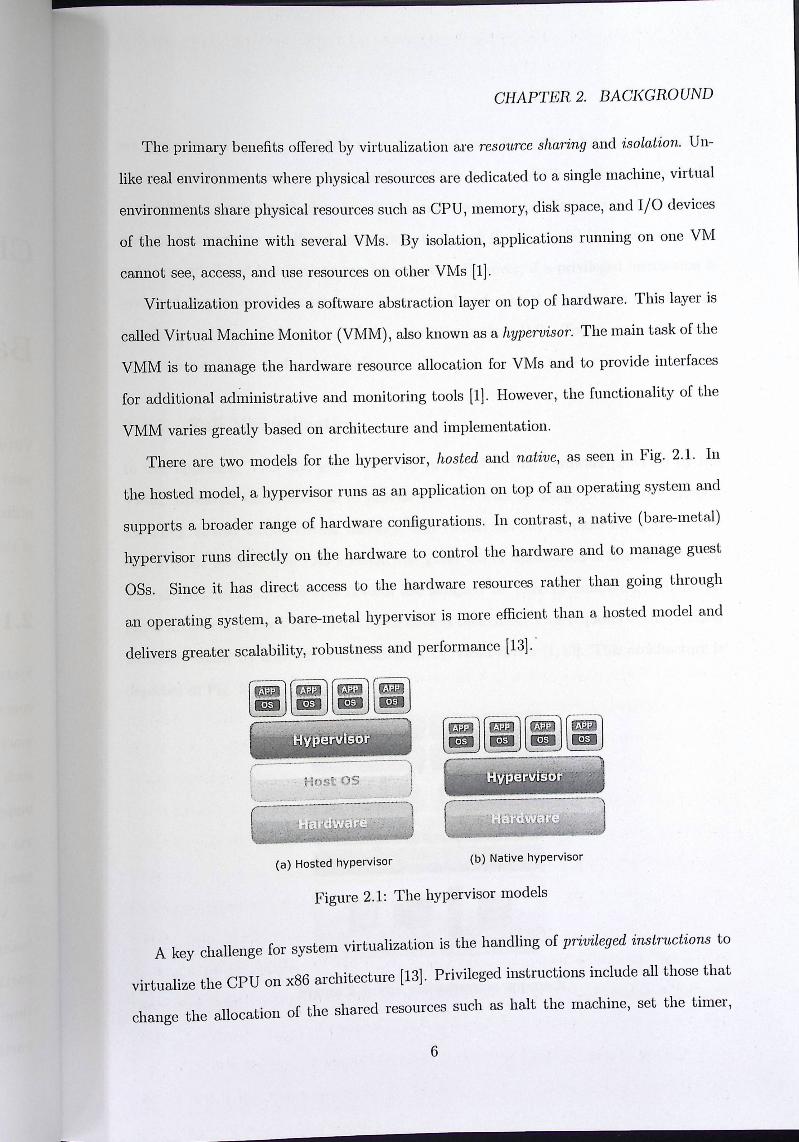
There are two models for the hypervisor, hosted and native, as seen in Fig. 2.1. In
the hosted model, a hypervisor runs as an application on top of an operating system and
supports a broader range of hardware configurations. In contrast, a native (bare-metal)
hypervisor runs directly on the hardware to control the hardware and to manage guest
OSs. Since it has direct access to the hardware resources rather than going through
an operating system, a bare-metal hypervisor is more efficient than a hosted model and
delivers greater scalability, robustness and performance [13].
:,/ Ei] sa,[ :] lid6#ii» \,. _ __ Hrn:t os J [:...:...== ::::..:..:w=-~~---J ~-y ~--_ • -_ ,-. J
(a) Hosted hypervisor (b) Native hypervisor
Figure 2.1: The hypervisor models
A key challenge for system virtualization is the handling of privileged instructions to
virtualize the CPU on x86 architecture [13]. Privileged instructions include all those that
change the allocation of the shared resources such as halt the machine, set the timer,
6

CHAPTER 2. BACKGROUND
set the program counter, and I/0 related instructions. The x86 architecture offers four
levels of privilege known as rings, numbered from O to 3. While applications typically
run in Ring 3 (user mode), the operating system needs to have direct access to hardware
and must execute its privileged instructions in Ring O (kernel mode) [14]. I user mode,
only non-privileged instructions can be executed. However, if a privileged instruction is
executed in user mode, an interrupt is generated and control is passed to an interrupt
handling routine, which is part of the operating system [14]. Today, two alternative
approaches exist to resolve this challenge:
2.1.1 Full Virtualization
In this approach, VMs and guest OSs run on top of virtual hardware provided by the
VMM. However, the VMM has to provide the VM with an image of an entire system,
including virtual BIOS, virtual memory, and virtual devices to allow the guest OS to
run without modification. As a result, the guest OS or application is not aware of the
virtual environment. The I/O devices are assigned to VMs by emulating well-known
physical devices in the VMM. The virtual devices then direct VMs requests to the physical
hardware either by host OS device driver or by VMM driver [1,13]. This architecture is
depicted in Fig. 2.2.
[ au' gag») i
rug== CPU NIC Memory Disk
Figure 2.2: Full virtualization approach
7

CHAPTER 2. BACKGROUND
The main advantage of full virtualization approach is that it supports any platform;
for example, one could run a RISC based OS as a guest on an Intel-based host. Full virtu
alization also helps provide complete isolation of different applications, which helps make
this approach highly secure. However, this approach has poor performance in trying to
emulate a complete set of hardware in software [1,13]. Even with different optimizations,
it is very difficult to get near-native performance from a fully virtualized environment
based on software techniques only.
In full virtualization approach, the VMM schedules the virtual machines in a manner
similar to how the OS schedules process and allocates CPU cycles to them. Using di
rect execution technique, a non-privileged instructions are executed directly on the CPU.
However, if the VM executes a privileged instruction, an interrupt is generated since the
VM run in user mode. The VMM then has to emulate the execution of the privileged
instruction. For example, if a VM issue an I/O operation, the VMM has to map that
I/O into an operation to be carried out at one of the real devices [13,14]. This context
switching between kernel and user mode break the overall system performance.
Binary Translation Technique
VMware, the commercial virtualization software, relies on a technique called binary trans
lation to provide a fully emulated machine. The binary translation technique, as shown
in Fig. 2.3, allows the VMM to run in Ring O for isolation and performance, while moving
the guest OS to a user level ring with greater privilege than applications in Ring 3 but less
privilege than the VMM in Ring 0. The VMM translates all guest OS instructions in the
memory and caches the results for future use, while user level instructions run unmodified
at native speed [13]. While this approach is complex to implement it yielded significant
performance gains compared to direct execution.
8

CHAPTER 2. BACKGROUND
Direct Exrgcutior
DB inary
Translation
Non-root Ring 3 Mode
Ring 2
Ring 1
Ring 0
Root Mode
Direct Execution
Trap to VMM
(a) Binary translation (b) Hardware assist
Figure 2.3: Full virtualization techniques
Hardware Assisted Virtualization
KVM [8], which stands for Kernel-based Virtual Machine, is a full virtualization solution
that takes advantage of hardware-assist features on x86 architecture such as Intel VT and
AMD- V to improve the performance of guest OSs. The first generation of hardware assist
features were added to processors in 2006, so that KVM hypervisor supports only newer
x86 hardware systems [15]. Using KVM, several fully VMs can be created and operated in Linux environments,
since KVM adds VMM capabilities to the Linux kernel. By adding virtualization support
to Linux kernel, the virtual environment can benefit from all the ongoing work on the
Linux kernel itself. Thus, researchers can focus their efforts on optimizing Linux and
KVM for the VM environment not replicating OS functions within the hypervisor.
In the IKVM architecture the VM is implemented as regular Linux process, schedule
by the standard Linux scheduler. Each virtual CPU appears as a regular Linux process.
Since a VM is implemented as a Linux process it leverages the standard Linux security
model to provide isolation and resource controls.
When using hardware assist features, additional operating modes, root and non-root
mode are added to CPU architecture to virtualize privileged instructions. Both of these )
modes support the four privilege rings just like the CPU architecture without virtualiza
9

CHAPTER 2. BACKGROUND
tion features. The VMM operates in root mode and has access to real hardware, while
the guest OS operates in non-root mode and its access to hardware is under complete
control of the VMM [14,15]. As depicted in Fig. 2.3 guest OS requests are set to trap to
the VMM, removing the need to implement the binary translation that was previously
required to virtualize privileged instructions.
While these hardware features reduce the overhead for virtualizing the CPU, a signifi
cant amount of resources are expended by the hypervisor in handling memory virtualiza
tion. Because the guest OS cannot directly access the physical memory, the hypervisor
must provide a virtualized memory implementation in which the hypervisor provides map
ping between the physical host memory and the virtual memory used by the VM. 'This is
often implemented using shadow page tables within the hypervisor.
AMD developed the Rapid Virtualization Indexing (RVI) feature, previously know as
nested page tables, and Intel developed the Extended Page Table (EPT) feature. These
are incorporated into the recent generation of Intel and AMD processors. These fea
tures provide a virtualized memory management unit (MMU) in hardware that delivers
significant performance improvements compared to the software only implementation.
KYM officially became part of the mainline Linux kernel as of version 2.6.20. KVM
bare-metal hypervisor consists of two main components: a set of kernel modules provid
ing the core virtualization infrastructure such as CPU and memory management, and a
userspace program that provides device emulation for I/O hardware devices, currently
through a modified version of QEMU [16]. QEMU provides an emulated BIOS, PCI bus,
USB bus and a standard set of devices such as IDE and SCSI disk controllers, network
cards, etc. KV M hypervisor can also be used with SPICE (Simple Protocol for Independent Com-
puting Environments) [17] to provide a complete solution for virtual desktop infrastructure.
SPICE is an open source remote computing, providing client access to remote VM display
and devices (e.g., keyboard, mouse, audio). SPICE achieves a user experience similar to
an interaction with a local machine, while trying to offload most of the intensive CPU
10

CHAPTER 2. BACKGROUND
and GPU tasks to the client.
2.1.2 Paravirtualization
Paravirtualization or OS assisted virtulaiuzation presents each VM with an abstraction
of the hardware that is similar but not identical to the underlying physical hardware [12].
This approach requires modifications to the guest OSs that are running in the VMs. As a
result, the guest OSs are aware that they are executing on a VIVI, allowing for near-native
performance [1]. As shown in Fig. 2.4, paravirtualization involve modifying the guest
OS to replace privileged instructions with hypercalls that communicate directly with the
VMM, removing the need to emulate hardware devices such as network cards and disk
controllers.
Ring 3
Ring 2 Direct Execution
Ring 1
Hypercalls to V MM
Figure 2.4: Paravirtualization approach
In this approach, VMs rely on physical device drivers to handle 1/0 operations. The
guest OSs have front end device drivers to handle 1/0 requests and pass them to a back
end device driver that interpret the I/O requests and map them to physical devices. The
back end driver resides on a separate privileged VM called driver domain [18]. Only
driver domain can access the control interface of the VMM, through which other VMs
can be created, destroyed, and managed. The driver domain model provides several
benefits including a safe execution environment for the device driver, support for legacy
device drivers, and fault isolation. However, these benefits come at the cost of high CPU
11

CHAPTER 2. BACKGROUND
overhead [19].
Xen [20] is an open source virtualization software based on paravirtualization ap
proach. Xen hypervisor runs directly on hardware, allowing the host machine to run
multiple modified guest OSs concurrently [12]. Modifying the guest OS is not feasible
for non-open source platforms such as Microsoft Windows. As a result, such operating
systems are not supported in a paravirtualization environment [21]. Recently, unmodified
guest OSs are also supported by Xen. In this mode, Xen provides fully abstracted VM
with hardware support (Intel VT and AMD-V) referred to as hardware virtual machine
(HVM).
Host (OomO) VM (Dom))
Xen Hypervisor
3 il I fl Disk IC Memory CPU
Figure 2.5: Xen architecture
Xen architecture, as depicted in Fig. 2.5, includes three components: the VMM, the
privileged domain guest referred to as Domain0 or Dom0, and unprivileged domain guests
referred to as DomainU or DomU. Dom0 has a unique privilege to access the hardware
through secure interfaces and to manage all aspects of Dom U such as starting, stopping
and I/O requests [21]. For many years, Linux has been used in DomO as a management
OS on top of the VMM and there was a Linux patch to transform the Linux kernel into
this Dom0. With the current release of Linux kernel 3.0, Xen hypervisor become part of
the mainline Linux kernel, allowing domain guests to run without the need to apply the
patch to the kernel.
12

CHAPTER 2. BACKGROUND
2.2 Network Virtualization
Network virtualization allows multiple heterogeneous architectures to run concurrently
in a shared network environment. Network virtualization often combines hardware and
software resources to deploy virtual networks for different architectures. Over the years,
the term virtual network has been used to describe different types of network virt ualization
or traffic isolation. These are:
2.2.1 Virtual Local Area Network
A virtual LAN (VLAN) is a group of logically networked hosts with a single broadcast
domain regardless of their physical connectivity. All frames in a VLAN have a VLAN
ID and network switches with VLAN support use both the destination MAC address
and VLAN ID to forward frames. Since VLANs are based on logical instead of physical
connections, configuration and management of VLANs are simpler than physical LANs.
VLANs provide isolation at Layer 2 [2].
2.2.2 Virtual Private Network
A VPN is a dedicated network connecting multiple sites using private and secured tunnels
over shared or public networks like the Internet. In most cases, VPNs connect geographi
cally distributed sites of a single enterprise. Each VPN site contains one or more customer
edge (CE) devices that are attached to one or more provider edge (PE) routers [2]. VPNs
are implemented in Layer 2, Layer 3 and higher layers.
2.2.3 Overlay Network
An overlay network is a logical network built on top of existing physical. network. The
Internet itself started off as an overlay on top of the telecommunication network. Overlays
in the Internet are typically implemented in the application layer. However, various
implementations at lower layers of the network stack also exist [2].
13

CHAPTER 2. BACKGROUND
2.2 Network Virtualization
Network virtualization allows multiple heterogeneous architectures to run concurrently
in a shared network environment. Network virtualization often combines hardware and
software resources to deploy virtual networks for different architectures. Over the years,
the term virtual network has been used to describe different types of network virtualization
or traffic isolation. These are:
2.2.1 Virtual Local Area Network
A virtual LAN (VLAN) is a group of logically networked hosts with a single broadcast
domain regardless of their physical connectivity. All frames in a VLAN have a VLAN
ID and network switches with VLAN support use both the destination MAC address
and VLAN ID to forward frames. Since VLANs are based on logical instead of physical
connections, configuration and management of VLANs are simpler than physical LANs.
VLANs provide isolation at Layer 2 [2].
2.2.2 Virtual Private Network
A VPN is a dedicated network connecting multiple sites using private and secured tunnels
over shared or public networks like the Internet. In most cases, VPNs connect geographi
cally distributed sites of a single enterprise. Each VPN site contains one or more customer
edge (CE) devices that are attached to one or more provider edge (PE) routers [2]. VPNs
are implemented in Layer 2, Layer 3 and higher layers.
2.2.3 Overlay Network
An overlay network is a logical network built on top of existing physical. network. The
Internet itself started off as an overlay on top of the telecommunication network. Overlays
in the Internet are typically implemented in the application layer. However, various
implementations at lower layers of the network stack also exist [2].
13

CHAPTER 2. BACKGROUND
2.2.4 Virtual Machine Networking
With the adoption of virtualization in data centers, a new layer of network virtualization
is emerging that provides inter- and intra- VM connectivity and has many of the same
functions provided by the physical networking hardware. Today, this layer is providing
connectivity to tens of VMs per physical machine. Networking in virtual environments
provides several advantages that are not present in physical networks such as software
flexibility and live migration which provides the ability to move a running VM between
physical hosts while network connections remain active. [22]. However, networking in
virtual environments impose a set of challenges that are not available in physical networks
such as network scaling and isolation.
The main network components provided by virtual networking, as shown in Fig. 2.6
are virtual Ethernet interfaces, used by individual virtual machines, and virtual switches,
which connect VMs to each other (3]. Virtual machines can also be configured with one
or more virtual Ethernet interface to offer different virtual network appliances for virtual
environments such as virtual routers and virtual .firewalls. Virtual routers are essential
components in the virtual networking infrastructure because they operate in much the
same way as physical routers, forwarding and routing packets based on standard routing
protocols such as OSPF and RIP. Virtual firewalls provide the usual packet filtering and
monitoring role provided via a physical network firewall. Thus, virtual networking com
ponents manage communication between co-located VMs, and connectivity to physical
machines. Modern OSs provide the ability to create virtual network interfaces that are supported
entirely in software. From the OS's point of view, these interfaces behave similar to
physical network interfaces. However, the virtual interface does not send-the packets into
a wire but makes them available to userspace programs running on the system. Virtual ' network interfaces are commonly referred to as TAP and TUN interfaces in Linux OS.
TAP interfaces operate with Layer 2 packets, while TUN interfaces can handle Layer 3
packets. VMs use TAP interface to create a network bridge with the physical network
14

CHAPTER 2. BACKGROUND
VMl VM2 VM3 VR
Virtual Ethernet Interfaces
Virtual Switches
Physical Ethernet Interfaces
Figure 2.6: Virtual networking components
interface [5]. Most of the virtualization approaches also provide some form of virtual networking.
For example, VMware virtualization software has a distributed switch for virtual machine
networking [23]. Linux-based virtualization platforms, including Xen and KVM, generally
use network bridging or Virtual Distributed Ethernet (VDE) switch. Network bridge acts
like an Ethernet hub; passing all traffic. While, VDE provides Layer 2 switching, including
spanning-tree protocol and VLAN support [24]. Open vSwitch [25] is an open source software switch that provides connectivity be-
tween the VMs and the physical interfaces. It implements standard Layer 2 and Layer 3
switching with advanced features such as traffic monitoring (e.g. NetFlow), port mirroring
(e.g. SPAN), basic ACL (Access Control List) and QoS (Quality of Service) policies. The
Open vSwitch consists of two components: a fast kernel module and lightweight userspace
program. The kernel module implements the forwarding engine, while the userspace pro
gram implements forwarding logic and configuration interfaces. Open vSwitch supports
multiple Linux-based virtualization software, including Xen and KVM [26].
Quagga [27] is an open source routing software that provides implementations of
TCP /IP based routing protocols such as OSPF, RIP, and BGP. In addition to tradi
tional IPv4 routing protocols, Quagga also supports IPv6 routing protocols [28].
15
CHAPTER 2. BACKGROUND
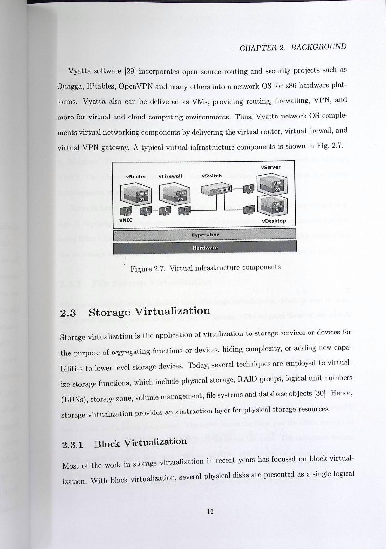
Vyatta software [29] incorporates open source routing and security projects such as
Quagga, IP tables, Open VPN and many others into a network OS for x86 hardware plat
forms. Vyatta also can be delivered as VMs, providing routing, fi.rewalling, VPN, and
more for virtual and cloud computing environments. Thus, Vyatta network OS comple
ments virtual networking components by delivering the virtual router, virtual firewall, and
virtual VPN gateway. A typical virtual infrastructure components is shown in Fig. 2.7.
v Server
vRouter
vNIC
vFirewall v Switch
iip' ", al
vDesktop
r. Hardware
Hypervisor 1
Figure 2. 7: Virtual infrastructure components
2.3 Storage Virtualization
Storage virtualization is the application of virtulization to storage services or devices for
the purpose of aggregating functions or devices, hiding complexity, or adding new capa
bilities to lower level storage devices. Today, several techniques are employed to virtual
ize storage functions, which include physical storage, RAID groups, logical unit numbers
(LUNs), storage zone, volume management, file systems and database objects [30]. Hence,
storage virtualization provides an abstraction layer for physical storage resources.
2.3.1 Block Virtualization
Most of the work in storage virtualization in recent years has focused on block virtual
ization. With block virtualization, several physical disks are presented as a single logical
16

CHAPTER 2. BACKGROUND
Vyatta software [29] incorporates open source routing and security projects such as
Quagga, IP tables, Open VPN and many others into a network OS for x86 hardware plat
forms. Vyatta also can be delivered as VMs, providing routing, firewalling, VPN, and
more for virtual and cloud computing environments. Thus, Vyatta network OS comple
ments virtual networking components by delivering the virtual router, virtual firewall, and
virtual VPN gateway. A typical virtual infrastructure components is shown in Fig. 2.7.
vServer
vRouter
vNIC
vFirewall vSwitch
vDesktop
Hardware
Hypervisor
Figure 2. 7: Virtual infrastructure components
2.3 Storage Virtualization
Storage virtualization is the application of virtulization to storage services or devices for
the purpose of aggregating functions or devices, hiding complexity, or adding new capa
bilities to lower level storage devices. Today, several techniques are employed to virtual
ize storage functions, which include physical storage, RAID groups, logical unit numbers
(LUNs), storage zone, volume management, file systems and database objects [30]. Hence,
storage virtualization provides an abstraction layer for physical storage resources.
2.3.1 Block Virtualization
Most of the work in storage virtualization in recent years has focused on block virtual
ization. With block virtualization, several physical disks are presented as a single logical
16

CHAPTER 2. BACKGROUND
device [30]. There are two common methods to deliver virtual storage with block virtu
alization or aggregation: host-based and network-based.
Host-based method uses the volume manager included on the host OS to deliver storage
virtualiztion. The volume manager provides a common way for managing and allocating
storage space on mass-storage devices. Most operating systems have a basic volume man
ager such as LV:M (Logical Volume Manager) in Linux and LDM (Logical Disk Manager)
in Windows. Third-party volume manager products are also available such as VMware
VMFS. The advantage of this method that it consolidates storage resources made from
heterogeneous storage systems.
Network-based virtualization is the most common method for delivering virtual stor
age. It depends on a storage area network (SAN) to connect and manage storage systems
using Fiber Channel (FC) switch or iSCSI storage networking protocol. This method has
the advantage of providing a single management interface for all virtualized storage.
2.3.2 File System Virtualization
File system virtualization is another type of storage virtualization, which is used to man
age shared network access to files in the file system. The simplest form of file system
virtualization is the concept of a network attached storage (NAS) such as Network File
System (NFS) and Common Internet File System (CIFS).
GlusterFS [31] is an open source cluster file system, distributed across multiple systems
and aggregates the total storage into a single storage pool. A GlusterFS cluster exposes
this pool as an NFS or CIFS mount point. The benefit of this model is that the underlying
storage becomes fully virtualized and can be distributed as widely as required. GlusterFS
has a client and a server component. The server stores the data, and the client connect to
servers with a custom protocol over TCP /IP to access the data. The important feature
of GlusterFS is that it is a pure software solution, able to run on commodity storage
hardware.
17

CHAPTER 2. BACKGROUND
2.4 Data Center Virtualization
Virtual data center (VDS) as sho · p· 2 8 · f 11 · 1 · · · , wn m '1g. . , 1s a ully-isolated virtual mfrastructure
environment where a user or a f v group o users can create and manage VMs, virtual networks
and storage pools. In addition, a set of ACLs is defined to allow different role management
for shared infrastructure resources.
System Virtualization
fiiii &s (izszssoi# l' ~
fi@ Network Virtualization
Storage Virtualization
Figure 2.8: Virtual data center
Virtualization of data center is the underlying technology for cloud computing. Cloud
computing provides on-demand network access to a shared pool of computing resources
like servers, storage and networking [32]. With cloud computing, IT enterprises and
providers can deliver the computing infrastructure as a service (IaaS). This eliminates
the need for cloud consumers to deploy and manage the hardware infrastructure.
Open Nebula [33] is an open source management software for data center virtualiza
tion. OpenNebula provides a virtual infrastructure environments for IT enterprises to
build their own private cloud using their internal infrastructures. The OpenNebula ar
chitecture includes several components specialized in different aspects of virtual infras
tructure management such as image and storage technologies, virtual networking, and the
18

CHAPTER 2. BACKGROUND
underlying hypervisor for creating and managing V.[Vls. OpenNebula provides different
interfaces (APis) that can be used with the underlying hypervisor, including KVM and
Xen. OpenNebula also supports a hybrid cloud model by using cloud drivers to interface
with public clouds or commercial cloud providers [34].
OpenStack [35] is an open source platform for building private and public IaaS clouds.
It includes three core software projects to orchestrate a cloud: OpenStack Compute,
OpenStack Object Storage, and OpenStack Image Service. These projects are designed
for large-scale deployments of virtual machines, virtual netoworks, and virtual disk images.
Open Stack provides drivers and APis required to interact with underlying hypervisors,
including KVM and Xen.
19
CHAPTER 2. BACKGROUND
underlying hypervisor for creating and managing VMs. OpenNebula provides different
interfaces (APis) that can be used with the underlying hypervisor, including KVM and
Xen. OpenNebula also supports a hybrid cloud model by using cloud drivers to interface
with public clouds or commercial cloud providers [34].
OpenStack [35] is an open source platform for building private and public IaaS clouds.
It includes three core software projects to orchestrate a cloud: OpenStack Compute,
OpenStack Object Storage, and OpenStack Image Service. These projects are designed
for large-scale deployments of virtual machines, virtual netoworks, and virtual disk images.
Open Stack provides drivers and APis required to interact with underlying hypervisors,
including KVM and Xen.
I9

Chapter 3
Literature Review
In recent years, there has been a fast growing interest in wireless LAN interface virtual
iztion. This chapter provides an overview of wireless LAN technology and describes the
different techniques for wireless LAN interface virtualization.
3.1 Wireless LAN Technology
Wireless LAN, also referred to as WiFi, is a local area network (LAN) that uses radio
frequency (RF) to communicate instead of using wire. Wireless LANs can be used as
an extension to an existing wired network or as an alternative to it. The IEEE 802.11
working group specifies the standards for wireless LANs, which govern wireless networking
transmission methods.
3.1.1 Wireless LAN Standards
Wireless LAN technology primarily uses two unlicensed frequency bands: 2.4-GHz and
5.0-GHz band. The 2.4-G1Hz band is the most widely used frequency bands in WLANs.
It is used by the 802.11b, 802.11g, and 802.lln IEEE standards. The 2.4-GHz frequency
band is subdivided into channels, with 3 non-overlapping channels. The 5-GHz range is
used by the 802.11a standard and the new 802.lln standard. The 5-GHz band is also
20
Chapter 3
Literature Review
In recent years, there has been a fast growing interest in wireless LAN interface virtual
iztion. This chapter provides an overview of wireless LAN technology and describes the
different techniques for wireless LAN interface virtualization.
3.1 Wireless LAN Technology
Wireless LAN, also referred to as WiFi, is a local area network (LAN) that uses radio
frequency (RF) to communicate instead of using wire. Wireless LANs can be used as
an extension to an existing wired network or as an alternative to it. The IEEE 802.11
working group specifies the standards for wireless LANs, which govern wireless networking
transmission methods.
3.1.1 Wireless LAN Standards
Wireless LAN technology primarily uses two unlicensed frequency bands: 2.4-GHz and
5.0-GHz band. The 2.4-GHz band is the most widely used frequency bands in WLANs.
It is used by the 802.11b, 802.11g, and 802.lln IEEE standards. The 2.4-GHz frequency
band is subdivided into channels, with 3 non-overlapping channels. The 5-GHz range is
used by the 802.11a standard and the new 802.lln standard. The 5-GHz band is also
20

CHAPTER 3. LITERATURE REVIEW
subdivided into channels, with a total of 12 non-overlapping channels [36].
Wireless networks use different modulation techniques to encode data over radio waves,
including DSSS, OFDM and MIMO. DSSS (Direct Sequence Spread Spectrum) is used
by 802.llb, which uses chipping codes to send redundant data to minimize interference.
OFDM (Orthogonal Frequency Division Multiplexing) is used by 802.lla and 802.llg.
This technique divides a channel into multiple subcarriers to achieve redundancy and
higher data rate. MIMO (Multiple-Input Multiple-Output) is used by the new 802.lln
and allows a device to use multiple antennas for receiving signals in addition to multiple
antennas for sending signals. MIMO technology can offer data rates higher than 100-Mbps
by multiplexing data streams simultaneously in one channel [36]. Table 3.1 provides a
comparison between wireless LAN standards.
802.llb 802.llg 802.11a 802.111
IEEE Ratified 1999 2001 1999 2008 Frequency Spectrum 2.4GHz 2.4GHz 5GIla 2.4GI-Iz 5GI-Iz Nonoverlapping Channels 3 3 12 3 12 Modulation Technique DSSS DSSS and OFDM OFDM MIMO MIMO Spatial Streams 1 1 1 1, 2 and 3 1, 2 and 3 Max Bandwidth llMbps 54Mbps 54Mbps 450Mbps 450Mbps
Table 3.1: Wireless LAN standards
The IEEE 802.11 defines various physical-layer (PHY) data rates for different WLAN
standards such as 1, 2, 5.5 and 11 Mbps for 802.llb and 802.llg. The PHY rates for
802.lla and 802.11g include 6, 9, 12, 18, 24, 36, 48 and 54 Mbps. 802.lln provides PHY
rate up 150-Mbps with 1-stream, 300-Mbps with 2-stream, and 450-Mbps with 3-stream.
The data rate is set and changes automatically to match the quality of the radio signal,
which varies across the coverage. This process is called rate adaption.
The wireless LAN throughput is bounded by the wireless channel bandwidth. It is clear
that the actual throughput is generally less than 50% of the theoretical channel bandwidth
due to the protocol overhead and other factors. For example, the typical peak throughput
of an 802.11a/ g wireless connection is actually less than 22Mbps and less than 200Mbps
for 802.lln when the peak bandwidth is 450Mbps. In addition, throughput decreases
21

CHAPTER 3. LITERATURE REVIEW
as the wireless client moves further away from the AP and when interference from other
wireless devices is present [37].
3.1.2 Wireless LAN Topologies
Original 802.11 networks support two topologies, as shown in Fig. 3.1, each of them
has different scenarios. In ad hoc mode, two wireless stations (STAs) can communicate
with each other directly in peer-to-peer manner. This is also called an Independent Basic
Service Set (IBSS). In infrastructure mode, wireless access point (AP) acts as a connection
point for member STAs to communicate. When there is only one AP, it is called a Basic
Service Set (BSS). When more than one AP is connected, then it is called Extended
Service Set (ESS). Multiple APs extend the coverage area of the wireless LAN [36].
~----~--~-------------.\~- Te" ' , s ¢ Z x
--~ : " ~
(a) Ad Hoc Mode (b) Infrastructure Mode
Figure 3.1: Wireless LAN topologies
The wireless network or workgroup name that clients connected to is called Service
Set Identifier (SSID). The SSID is mapped to the Media Access Control (MAC) address
of the AP. When a client moves from one AP to another with the same SSID, the SSID
· th but the MAC address changes to the new AP with the better radio remams ' e same, u
· al Tl • · · called roaming The two APs also need to be on different channels, sign . his process1s "
f nges to prevent co-channel interference [36]. or requency ra ,
22

CHAPTER 3. LITERATURE REVIEW
3.1.3 Wireless LAN Connection
The SSID is used by wireless LAN devices or client stations to connect and become part
of a wireless network. This is accomplished through processes known as passive and active
scanning. Passive scanning allows wireless LAN devices to listen for beacons advertising
specific information about APs in the area such as RF channel available data rates and , ,
much more. In active scanning, wireless LAN devices send a broadcast probe request
to APs within area range. Any AP has a matching SSID, send a probe response to the
wireless device. If more than one AP responds, the device selects the AP with better
radio signal [38]. In order to access network resources, wireless LAN devices use an authentication pro
cess. This process is required in order for the wireless LAN devices to join the wireless
network and participate in exchanging data frames. The IEEE 802.11 standard addresses
two types of authentication: open system and shared key. Open system authentication
enables any wireless device to authenticate to an AP. However, shared key authentication
relies on the fact that both the wireless device and the AP must have the same shared key
or passphraso. This method differs from open system authentication in that shared key
authentication is used for both device authentication and data encryption. Shared key
authentication requires the use of Wired Equivalent Privacy (WEP) protocol. Because
WEP make a network vulnerable to intrusion, it's replaced with a more secure standard
such as WPA2/IEEE 802.11i [38]. The association process takes place after a wireless device has been successfully au-
thenticated. In association state, the authenticated device can pass traffic across the AP
to a wired network and other associated devices. IEEE 802.11 authentication and associ
ation occur at the AP before any upper layer authentication such as IEEE 802. 11x [38].
23

CHAPTER 3. LITERATURE REVIEW
3·2 Network Interface Virtualization
A network interface can be sh · d d h · · · · are anc ence virtulized using either software or hardware
based approach, as shown in Fig. 3.2.
3.2.1 Software-based Approach
In software-based approach, network interface virtualization is implemented completely
in software to provide virtual network interfaces (VIF) for multiple VMs [7, 19,39]. I
this approach, bridging functionality is often enabled on the physical network interface to
give all VMs access to the same physical network.
V M VM
V MM
VM
VIF Driver
VM
VIFF Driver
NIC
V MM
VIF VIF
SRV-IO NIC
(a) Software-based approach (b) Hardware-based approach
Figure 3.2: Network interface virtualization approaches
Full virtualization technique provides virtual network interfaces by emulating legacy
Ethernet devices for simplicity. The virtual network interfaces appear to the VM as
virtualized hardware devices within the hypervisor. In this technique, no modification is
required for the guest OS. However, there is a significant performance overhead <lue to
the context switching between VM and hypervisor. In the paravirtualization technique,
the para-virtualized driver is used in the guest OS to achieve high I/0 performance. But,
this method requires modifying the guest OS and having a special driver to expose some
details of the hardware [7].
24

CHAPTER 3. LITERATURE REVIEW
3.2.2 llardware-based Approach
The second approach depends on hardware virtualization support to partition a physical
network device to multiple virtual network interfaces, then each virtual interface can be
assigned directly to a specific VM. While this approach reduces the performance overhead
of software-based network interface virtualization, it increases the complexity, maintain
ability and cost of network devices [7, 19,39]. An example of hardware-based approach is
Single Root 1/0 Virtualization (SR-IOV) where a single PCI device can be divided into
multiple Virtual Functions (VFs) (40]. Each VF can then be used by a VM, allowing
one physical device to be shared among multiple VMs. As a result, close to native I/O performance can be achieved, in addition to fair sharing of the bandwidth [41].
3.3 Virtualization of WLAN Interface
Virtualization of wireless LAN interface is more complicated than for wired network in
terface because the capacity of wireless channel varies with radio signal strength and
interference from other wireless LAN devices. This requires to include complex man
agement functions into wireless devices to achieve efficient and reliable communication.
Examples of such management functions include data rate adaption, power management,
and power control. The device driver, which is part of the OS, is also involved in such
management functions for control and configuration. In contrast, wired LAN devices are
data centric and have very little management functions [7,42]. The limitations of full virtualization approach for the wireless network interface come
from the difficulty to emulate WLAN management functions. IEEE 802.11 MAC functions
are a superset of 802.3 MAC functions, and many management functions will get lost when
emulating IEEE 802.11 device as 802.3 devices. Using a paravirtualization approach is
technically possible. However, the WLAN management functions are complex and the
management interface between host driver and wireless LAN device is often proprietary,
which requires support in the hyper visor. With a hardware based virtualization approach
25

CHAPTER 3. LITERATURE REVIEW
such as SR-IOV, the wireless network interface card (NIC) is equipped with multiple
radio resources that operate on different channels. This approach significantly increases
the complexity and cost of wireless NIC [7].
A typical WLAN device consists of: RF transceiver, Baseband, and MAC layer. The
RF transceiver performs radio signal transmitting and receiving, while the Baseband
mainly responsible for digital signal processing. RF transceiver and Baseband are gener
ally referred to as PHY layer. The MAC layer often consists of a hardware controller on
the WLAN device and a software driver on the host computer. Most of the wireless LAN
functions such as authentication and authorization are performed at MAC layer [5,7].
In the beginning, the MAC layer was entirely managed by the firmware on the wireless
LAN device. This approach is called FullMAC, where full MAC layer functionality is ex
ecuted by the hardware controller on the wireless device. New implementation of wireless
LAN devices is based on SoftMAC approach, where most of the MAC layer functionality
is moved to device driver on the host computer, with the firmware providing a set of func
tional primitives. This approach provides a high degree of software control over the MAC
layer functions, while still allowing the PHY layer to define the radio waveform [5,43].
3.3.1 Virtualization Approaches
The application of virtualization for wireless networks is discussed in Virtual Radio [44]
as a radio resource sharing framework. The goal of Virtual Radio is to allow different
virtual radio networks to operate on top of a common shared infrastructure and share the
same radio resources without interfering with each other.
Virtualization of the wireless radio can be achieved in multiple ways such as in space,
frequency and time.
• Space Division Multiplexing (SDM): This is the simplest approach, where
1 · ] rces are partitioned in space. Each physical node hosts one virtual physicai resource
d · experiment A wireless experiment is assigned a set of physical
no e per runnmg ·
l 1 tl t t. ns1111·tting no<les from different experiments do not interfere with
notes such cha wrau
26

CHAPTER 3. LITERATURE REVIEW
each other [45].
• Frequency Division Multiplexing (FDM): In this approach, different experi
ments are partitioned in the frequency domain for their communication needs. Each
physical node is equipped with multiple virtual nodes, each configured with the fre
quencies allocated to the corresponding experiment. Interference between the dif
ferent experiments are avoided by ensuring that different experiments are assigned
non-interfering channels [45].
• Time Division Multiplexing (TDM): In this case, the entire wireless network
is partitioned in time across the different experiments. Each experiment is assigned
a time slot during which each physical node in the system activates the virtual node
corresponding to this particular experiment [45].
Radio virtualization in the context of software defined radio is discussed in Virtual
Flow Pipelining (FVP) architecture to provide a common interface to layers above the
MAC layer. The goal of VFP is to support virtualization of traffic flows using scheduling
mechanisms for allocations/reservations of hardware resources. The allocations of the
hardware resources create Virtual Flow consisting of a set of functions and their scheduling
requirements [46]. MultiNet [47], which was later named VirtualWiFi, proposes a software based ap
proach to virtualize a single wireless interface. Virtualization of wireless LAN interface
is implemented with intermediate driver, called MultiNet Protocol Driver, that continu
ously switches the radio resources across multiple wireless networks. However, MultiNet
approach was not designed to support VM environment. This approach has been adopted
in Microsoft Windows 7 to give a user the ability to simultaneously connect to multiple
IEEE 802.11 networks with one WiFi card [5,7]. Recently, a novel virtualization approach on 802.11 MAC layer has emerged in the
wireless industry. Multiple virtual wireless LAN interfaces are separated at MAC layer
sharing the same PHY layer. As shown in Fig. 3.3, multiple virtual MAC entities can
27

CHAPTER 3. LITERATURE REVIEW
be active and share a common PHY 1 · · · · · · ayer via Time Division Multiplexing (TDM) on the
same channel [5.7]. This approach di li5· 're uces costs, eliminating co-channel mterference, and
offering smooth roaming as clients move through the WLAN's coverage area. WLAN
products that provide support for such approach include Atheros, Intel, and Marvell.
Wireless NIC Driver
VIF VIF
PHY
Wireless NIC
Figure 3.3: Wireless network interface virtualization
The reason that multiple virtual MACs sharing the same PHY layer can function as
separate wireless LAN interfaces is due to the broadcast nature of the wireless link. As
long as the RF layer is tuned to a particular channel, it can transmit/receive packets on
that channel. The RF layer just needs to stay on that channel and receive all packets.
Irrelevant packets can be filtered out using MAC filters to save power and computing
time. The MAC layer is responsible for identifying a packet based on the SSID and
source/destination MAC addresses [7]. In the case that different virtual MACs need to operate on different RF channels,
a time-critical scheduling is required for multi-channel MAC functions. Implementing
such solution will allow the PHY layer to switch between different RF channels and keep
virtual MACs in synchronization with the associated networks. Several research efforts
have been made in implementing multi-channel virtualization approach such as Net-X [48]
and FreeMAC [49]. Virtual Wii [7] proposes a hybrid wireless virtualization approach with the goal
to expose wireless LAN functionalities inside the guest VM; each virtual machine can
establish its own connection with self-supplied credentials; and multiple separate wireless
LAN connections are supported through one physical wireless LAN interface. A prototype
28

CHAPTER 3. LITERATURE REVIEW
of Virtual WiFi is implemented KVMh : s s5 in IM hypervisor with an Intel Wili device to support
IEEE 802.11g compliant WiFi interfaces. In contrast, this work is ported to deploy
multiple wireless networks on a si lc sh rod oh 5 df1 5 " t asingle share physical infrastructure with different security
standards. At the same time, these wireless networks should be isolated from each other
at a satisfactory performance level comparable to real hardware environments.
3.3.2 Usage Scenarios
Virtualization of the WLAN interface enables several usage scenarios for wireless network
ing, some of these are:
• Simultaneous Connectivity: a wireless device can connect to multiple wireless
network simultaneously. For example, one virtual interface operates in STA mode
to connect to an AP, while another virtual interface operates in ad-hoc mode to
create a peer-to-peer wireless network.
• Wireless Relay /Extension: a wireless client can extend the coverage area of the
network by creating a second virtual interface in AP mode, allowing remote clients
outside the basic operating range to relay data to the main AP.
• Soft Handover: a wireless client can use a second virtual interface to scan all
available APs, while the first virtual interface is connected to the wireless network.
After selecting the new AP, a client can authenticate and associate with it without
losing the connection with the current AP. By this scenario, we can void packet loss
and long delay in real-time applications such VOIP and video streaming [5,50].
• Multi-Streaming Service: a mobile device can communicate with multiple APs
operating on different channels, as the device has several virtual interfaces. The most
stable connection becomes main-connection and others become sub-connections. By
this scenario, we can improve streaming performance such as multi-path streaming
without relay server [51].
29

CHAPTER 3. LITERATURE REVIEW
• Wireless Mesh Network (WMN): a multi-hop WMN is built through virtual
interfaces created at some mesh nodes. In this case, a mesh node is configured to
work in STA mode and acts as AP by creating a second virtual interface in AP
mode. Thus, remote clients located outside the coverage range (wireless cell) can
get access to the network via clients connected to any AP in the wireless cell [50].
• Virtualized Environment: a virtual machine can establish its own wireless LAN
connection by creating a virtual interface in STA mode. In this case, multiple wire
less connections are supported through one physical wireless LAN network inter
face [7]. This thesis provides a solution to get the functionality of multiple separate
wireless networks in a VM environment.
30

Chapter 4
Design and Implementation
An ideal scenario in VM environments is to assign a virtual network interface to each VM
using only one physical network interface to access the real network. However, most of
the existing virtualization techniques have focused mostly on sharing the wired network
intedace. In other words, sharing a wireless network interface is not supported by the
VMM due to the difficulty to emulate wireless LAN management functions. Therefore,
current virtualization techniques require a separate physical wireless LAN interface for
each VM to have its own wireless network.
This chapter describes a new approach to address the above issue using only one
physical WLAN interface. It also describes the implementation of such approach based
on open source virtualization techniques and multi-SSID capability given by Atheros
WLAN devices.
4.1 Wireless LAN Virtualization
With the introduction of IEEE 802.11n and the increase in bandwidth, wireless LAN vir
tualizat ion is required as an alternative approach for deploying multiple wireless networks
with different authentication methods. Wireless LAN virtualization enables several vir-
t 1 · l t» ·ks to coexist on a common shared physical WLAN device. Multiple
uan wireless efwOr · t
1 • t f be created on top of the same radio resources, allowing the same
vir+uar inter!aces can
31

CHAPTER 4. DESIGN AND IMPLEMENTATION
functionality as in multi-radio solution.
All virtual interfaces operat I · · e concurrently without considering the physical nature
of the wireless medium as well as physical management tasks. Each virtual interface
abstracts a single wireless device d l · t · · · an has its own wireless network and its own unique
MAC address. From the applicati + : h 5 ion's perspective, the virtual wireless network behaves
like wired Ethernet, but is wireless.
Using the wireless LAN virtualization technique, a virtual interface (VIF) can be
configured to operate as virtual access point (AP) and also as a virtual station (STA).
4.1.1 Virtual Access Point
A virtual AP is a logical AP constructed by wireless LAN virtualization technique and
is bound to a virtual network interface. Each virtual AP independently keeps the con
figuration and service of the wireless network. In this way, several virtual APs can be
configured on top of solely one physical wireless LAN device.
When a single physical wireless device supports multiple virtual APs, as shown in
Fig. 4.1, each virtual AP appears to stations as an independent physical one. Since each
virtual AP is logically separated, wireless LAN providers may use virtual APs to offer
multiple services on the same physical infrastructure. Alternatively, virtual APs can be
shared by multiple providers allowing each provider to offer separate services for their
subscribers [6]. A virtual AP acts as the master device in a virtual wireless network and operates in
much the same way as real AP, allowing wireless stations to communicate with each other
by managing and maintaining a list of associated stations. In general, the virtual AP
consists of two parts: control plane and forwarding plane. The control plane is concerned
with the information that define the functionality of the AP such as SSID, operation
mode, and RF channel. While, the forwarding plane defines the part of the AP that uses
a lookup table as a base to forward packets to its destinations [52]. Host AP [1O] is an open source software for controlling wireless LAN authentication
32

CHAPTER 4. DESIGN AND IMPLEMENTATION
+ ., ·
AP1 (( SSI
(a) Physical APs
.fl a A» ' ±!' ±
/. l .
·11: 'Fs535
.·.1 .
(b) Virtual APs
Figure 4.1: Multiple virtual access points
and association. It implements IEEE 802.11 AP management and provide support for
several security mechanisms such as WPA, WPA2/IEEE 802.11i, and IEEE 802.lX. The
current version of HostAP support Linux operating system and OpenBSD [10].
4.1.2 Virtual Station
By wireless LAN virtualization technique, a virtual interface can also be configured to
operate as a station device. In this way, a wireless device can be connected to different;
networks. This enables concurrent connections based on a single wireless device. For
example, one virtual interface can be connected to open network for public Internet access
while another virtual interface is connected to secure network for private applications.
A virtual STA functions as a managed device in a virtual wireless network and is
associated to an AP after successful authentication. WPA Supplicant [53] is an open
source software for controlling the wireless connection. It implements the component
that is used in the wireless stations for Linux, OpenBSD, Mac OS, and Windows with
support for WPA and WPA2(IEEE 802.1 li/RSN) features [54].
4.2 Virtual WLAN Approach
B · t t· · less LAN virtualization technique into the hypervisor, the wireless
y mtegramg wire LAN interface can be shared among several VMs. To each VM one or more virtual
33

CHAPTER 4. DESIGN AND IMPLEMENTATION
wireless interfaces can be assigned A h . . · s s own in Fig. 4.2, VIFs are configured to operate
in one of the wireless operating modes s . . , specifically the AP mode, and then can be assigned
to virtual networking infrastructure.
VMI VM2 VR
Virtual Ethernet Interfaces
Virtual Switches
Virtual Wireless Interfaces
Physical Wireless Interfaces
Figure 4.2: Virtual WLAN approach
The main goal of this approach is to combine wireless network functionality into a
common virtualized environment and to achieve performance levels comparable to the
native hardware wireless LAN. A similar approach named virtual WFi [T] has been taken
to provide wireless LAN client functionality inside VMs. However, virtual WiFi approach
is intended to support mobile client environments where the VM runs on the client device
and has to beware of the wireless interface to establish its own wireless connection.
This approach is suitable for virtualizing wireless LAN infrastructures, where multiple
separate wireless LANs can be deployed on a shared physical infrastructures with different
security mechanisms [55]. Since each virtual wireless LAN is logically separated, wireless
LAN providers may use virtual WLANs to offer multiple services on the same physical
infrastructure. Alternatively, virtual WLANs can be shared by multiple providers allowing
each provider to offer separate services for their subscribers [6].
To wireless LAN clients, each virtual WLAN appears to be an independent physical
AP or router. In other words, a separate, distinctly configured virtual APs can run
34

CHAPTER 4. DESIGN AND IMPLEMENTATION
simultaneously with different add· · - r. . · · · • ressing, forwarding, and wireless security settings. For
example, one virtual AP can be confi rod tc id / · · igure o provide WPA,'WPA2 security, while another
virtual AP is configured to offer Open or WEP :ti it tc ·li it connectivity +0 clients.
The virtual WLAN approach is based on the Atheros WLAN chipset which supports
concurrent wireless connections sharing the same PHY layer of the wireless LAN device.
This capability in wireless LAN devices is also referred to as multi-SSIDs, where each
SSID is equivalent to a VLAN on a wired network. I extend multi-SSIDs capability
to operate in the virtualization environments, where each virtual WLAN can have its
own addressing, forwarding, routing, and security mechanism. In this approach, virtual
WLANs belonging to the same wireless network interface share the same radio channel
being used and thus the available bandwidth.
To emulate a physical AP, it is necessary to provide the emulation at different layers
such as layer 2 (MAC), layer 3 (IP), and above. At the MAC layer, the behavior of a
physical AP is being emulated by allocating a distinct MAC address and SSID to each
virtual AP. At the IP layer, it is emulated by allocating a distinct IP address and po
tentially a Fully Qualified Domain Name (FQDN) to each virtual AP. In higher layers,
the emulation can be carried out by providing each virtual AP with a unique authentica
tion and accounting configuration such as (a shared key, or EAP methods with RADIUS
authentication), or SNMP communities.
In our approach, a virtual wireless AP or router is constructed by configuring the VIF
to operate in AP mode. This sets the main functionality of the wireless AP such as IEEE
802.11 operation mode, SSID, and security mechanism. Once configured, the wireless
interface is attached to a virtual switch to enable MAC forwarding similar to a physical
AP. Then, the virtual AP interface is connected to a virtual router (VR), in the same
way as the virtual Ethernet interface, to enable IP forwarding and routing.
S. h' h dds wireless LAN infrastructure functionality to virtual environ- ince tis approact a
• b d l d f . different wireless LAN systems on the same host machine ments, it can e ep oye 01
• e %. and intrusion detection, providing secure virtual wireless such as authentication services
35

CHAPTER 4. DESIGN AND IMPLEMENTATION
LAN solution on the same hardware.
4.3 Benefits of Virtual WLAN Approach
The virtual WLAN approach provides the following benefits:
• Virtual WLAN approach doesn't require the use of multi-SSIDs with VLANs to
provide traffic differentiation for virtual SSIDs. When using multi-SSIDs, all traffic
from each virtual SSID will be handled by a common forwarding table. When using
multi-SSID with VLANs, the traffic from each virtual SSID is tagged with a unique
VLAN ID to have a unique forwarding table. Although this solution provides traffic
differentiation for virtual SSIDs, it requires an additional Ethernet switch to control
the traffic for each virtual SSID.
• Virtual WLAN approach doesn't require the use of Wireless LAN Controller/Switch
to control the wireless network. WLAN Controller is used to manage several
lightweight APs from a single location. Unlike standalone APs that require the
configuration for each device, a wireless LAN controller/switch can be used as a
centralized device for configuration and management. By using the virtual WLAN
approach, it is possible to manage the virtual APs representing the virtual WLANs
and all wireless parameters like the channel to be used, operation mode, and trans-
mission power from the virtual environment.
• Each virtual WLAN can have its own access authentication and encryption method.
• Each virtual WLAN can have its own IP addressing and routing, DHCP (Dynamic
Host Configuration Protocol) and DNS (Domain Name System) services, and fire-
wall and IDS (Intrusion Detection System) features.
F. ll · 1 WLAN approach enables the creation and configuration of different
o 'inai!y, virtuai 8 <
3r LAN ste without the need to purchase and deploy physical wireless wireless systems
LAN infrastructure.
36
4.4
CHAPTER 4. DESIGN AND IMPLEMENTATION
Implementation of Virtual WLAN Approach
The multi-SSID capability ° b i ·y given Y the Atheros chipset allows implementing multiple
IEEE 802.11 networks on a singl l · 1 · 1 · · · · le physical wireless device with Linux OS (Linux ker
nel version 2.6.33 and higher). since it include +le de dr ' hi ludes a wireless tevice [river supporting tius
capability.
WLAN device driver in Linux is divided into two modules: kernel module (hardware
dependent) and protocol module (SoftMAC). The hardware dependent module varies be
tween wireless device vendors since each vendor provides different hardware capabilities.
The Soft MAC handle most of the MAC functionality with respect to IEEE 802.11 pro
tocol. The SoftMAC implementation in Linux is known as mac80211. The mac80211
depends on a wireless configuration API, namely cfg80211, for both the registration to
the networking subsystem and for configuration [43,56].
The wireless driver for Atheros WLAN devices was initially developed by the maclwifi
project, and then became part of the Linux kernel. The implementation model of Linux
kernel WLAN driver is currently based on Soft MAC wireless devices. For the time being,
Linux kernel supports all wireless modes with PCI/PCI-Express Atheros WLAN devices
only [43]. In order to implement our approach, we used a conventional PC with a wireless LAN
card based on the Atheros IEEE 802.1 1n chipset (ath9k). It had an Intel Core 2 processor
with VT support, Gigabit Ethernet interface and 3 GB RAM. Ubuntu Linux has been
chosen to host the virtualization environment for virtual WLAN approach. We used KV M
as a bare-metal hypervisor and libvirt as front-end for managing VMs. With libvirt, there
t nt tools. virt manager as graphical user interface (GUI) and virtsh
come wo manageme • - ·
as command line interface ( CLI).
Tl · 1 · 1 · t •faces have been created using a CLI configuration utility
e virtuai wireless inter/a · • d " O created the interfaces have been configured to function as in Linux name 1w . nee ,
· • 1 STA It is essential for all VIFs to have a unique MAC address, virtual AP or virtual ·
. . l "tl ""£ nfig hw" command or "macchanger" utility. which can be assigned with 'itcO
37
CHAPTER 4. DESIGN AND IMPLEMENTATION
A virtual AP functionality has b · 1 d · . een unp emente usmg the HostAP userspace. The
virtual AP depends on HostAP to handle th 1ti: li :. s ] e authenticating clients, setting encryption keys,
establishing key rotation policy, and other aspects of the wireless infrastructure. The
HostAP use the netlink driver (1l80211) to create an AP mode interface for wireless
traffic and a monitor mode interface for receiving and transmitting management frames.
The AP mode interface has been connected to a VDE switch to enable MAC forwarding
similar to a real AP or router.
For testing our approach, three virtual wireless routers have been hosted on the PC
with a shared Internet connection. We created three virtual APs in IEEE 802. llg oper
ation mode, and three virtual routers running Vyatta OS. Each virtual router had two
virtual Ethernet interfaces. One of them was connected to the virtual AP interface and the
other to the physical Ethernet interface using the Linux interface bridging functionality.
Each virtual router acted as a DHCP server and DNS forwarder for its own virtual
WLAN and each virtual AP broadcasted different SSIDs to distinguish the wireless net
works. NAT (Network Address Translation) functionality was also added to the virtual
interface facing the Internet to maintain public IP addresses and to enhance wireless net
work security. Using these virtual routers, different wireless LAN clients could access the
Internet with different wireless LAN security mechanisms. A detailed implementation of
the virtual WLAN platform is described in Appendix A.
38

-
Chapter 5
Testing
Testing the functionality and performance of WLAN is used to lid..t l f _ va 1 a e our approacn or
WLAN infrastructure virtualization. This chapter describes a number of basic tests that
compare and quantify the performance of WLAN. The tests are executable on both real
and virtual WLAN. The objective of the performance tests is to evaluate the impact of
virtual software layer on wireless LAN performance.
5.1 Security Testing
Testing the security of WLAN typically includes authentication and encryption methods.
Wireless stations connected to the network typically have the same access rights to the
resources as wired stations on the LAN. However, there are a great number of security
risks associated with wireless LANs. As a result, it's very important to define an effective
authentication and encryption methods that guard against unauthorized access to the
resources. The most common authentication methods used in WLAN are WEP, WPA with TKIP
as the cipher or WPA2 with AES-CCMP as the cipher. WPA and WPA2 are available
in two versions: Personal and Enterprise. Both use the same cryptography algorithm,
but differ in how the encryption keys are generated and managed and how users are
authenticated. WPA and WPA2 Personal, also known as pre shared key (PSK), use static
39

>
CHAPTER 5. TESTING
keys with no authentication of the user or the d · WPA E • · d 1 evice. interprise uses rantomy
generated keys that are changed regul l K : · · tarly. I£eys are exchanged during user authentication,
which takes place via the 802.lX authentication protocol.
WPA and WPA2 Enterprise support multiple different authentication methods over
the Remote Dial-in User Services (RADIUS). RADIUS is widely used by WLAN service
providers for authentication, autherization and accounting. It passes login credentials of
a WLAN station to an AP and then to a RADIUS server using 802. lX authentication
protocol.
Extensible Authentication Protocol (EAP) is an authentication framework used by
IEEE 802.lX protocol for the transport of encryption keys. The common EAP meth
ods used in wireless networks are PEAP (Protected EAP) and EAP-TLS. But EAP-TLS
method requires a public key infrastructure (PIG) that increases the cost of WLAN de-
ployment.
The test setup for the virtual WLAN approach is the same in all the tests that were
conducted. The test scenario for virtual WLAN approach is shown in Fig. 5.1. In our
test setup, three virtual 802. llg APs are mapped to a different SSIDs and have different
security settings. All virtual WLANs are DHCP-enabled and obtain addresses from a
different DHCP pool. Thus, stations have a different network settings based on the SSID.
Web Server
~ .-• u 10.0.0.0/24- Wired NIC
««> ill° 1 'IJ WPA/WPA2 PSK ~~ i 192.168.2.0/24 = VAP3 ~:;.--'~TAJ 802.1x EAP 192.168.3.0/24
Figure 5.1: Test scenario
. . . . 1 WLAN approach has been tested for both home and The functionality of the virtua
. 1 AP+ re configured with different authentication enterprise environments. The virtual 's WCI
40

mp
CHAPTER 5. TESTING
methods in order to access the wir d _ e network such as WEP, WPA and WPA2.
5.1.1 Home WLANs
In this test, virtual WLANs wer fi e con gured for the home environment. The virtual APs
were configured with different . t . secun y settings such as WEP, WPA-PSK and WP2-PSK.
Objective
Test functionality of the security feat f h Lures tor home environments.
Methodology
• The physical host was configured to run three virtual wireless APs or routers with
two virtual network interfaces.
• The first virtual network interface was bridged directly to the wireless LAN interface
on the physical host.
• The second virtual network interface was bridged directly to the wired Ethernet
interface on the physical host.
• Each virtual WLAN was configured to support different security scttings (WEP,
WPA-PSK and WPA2-PSK).
• The wireless clients were configured to join these virtual APs.
Results
The features tested in this test are security features that available in virtual WLAN
approach for home environments. The virtual APs were mapped to different SSIDs and
have different IP address settings based on the SSID. These SSIDs also have different
security settings (WPA-PSK with TKIP or WPA2-PSK with AES-CCMP or Shared Key
with WEP). All stations connected to a certain virtual AP could access the wired network
but could not reach stations belonging to another virtual AP.
41

>
CHAPTER 5. TESTING
5.1.2 Enterprise WLANs
In this test, virtual WLANs wr fi ere con gured fc it . . or enterprise environments. The virtual APs
wore configured with the most ' common enter .· · erprise security settings such as WPA-802.1X and WP2-802.1X. Objective
Test functionality of the security feat . f . . . ures tor enterprise environments.
Methodology
• The physical host was configured to run three virtual wireless APs or routers with
two virtual network interfaces and a VM act as RADIUS server.
• The first virtual network interface was bridged directly to the WLAN interface on
the physical host.
• The second virtual network interface was bridged directly to the wired Ethernet
interface on the physical host.
• The RADIUS server was connected to all virtual wireless APs.
• Each virtual WLAN was configured to support different security settings for enter
prise networks (WPA-802.lX and WPA2-802.1X).
• The wireless clients were configured to join these virtual APs.
Results
The features tested in this test are security features that available in virtual WLAN ap
proach for enterprise environments. The virtual APs were mapped to different SSIDs
and have different. IP address settings based on the SSID. These SSIDs also have difler
ent security settings (WPA-802.lX with TKIP or WPA2-802.1X with AES-CCMP). AII
stations connected to a certain virtual AP could access the wired network but could not
42

DI
CHAPTER 5. TESTING
reach stations belonging to another virtu.d AP A a • ccess may be defined differently in a real
network, but in this test the access rights are the same.
5.2 Performance Testing
Testing WLAN performance primarily includes two test metrics: throughput and response
time. The throughput of WLAN is defined as the speed with which a user can send and
receive data between the client and the AP. Theoretically, the maximum TCP rate of
802.llg network is 24.4 Mbps and the maximum UDP rate is 30.5Mbps. UDP throughput
is higher than TCP throughput because there is less protocol overhead associated with
UDP [57]. 'Therefore, TCP throughput is the most relevant metric in WLAN performance
measurements.
Response time is measured either in one-way, i.e. from the source sending a packet to
the destination receiving it, or round-trip, the one-way latency from source to destination
plus the one-way latency from the destination back to the source. Round-trip latency is
most often used because it can be measured from a single host.
5.2.1 TCP Throughput
TCP throughput indicates the maximum network throughput of a system or network.
Since TCP is the protocol of choice for most network services, it is highly optimized by
the OS, device driver and hardware. An optimal TCP performance in WLANs requires
l · h d d tight integration between the network interface and device driver. 1igI spee memory an a
rr TCP · a virtualized system this integration must extend through lo test performance in
the virtualization layer.
Objective ·... rk throughput (Mbps) of the virtual WLAN using TCP.
Determine the maximum network 1
43

CHAPTER 5. TESTING
Tools
IPerf [58], the open source tool, is used t . 1 • o measure TCDP throughput. JPerf uses Java
graphical interface to measure and graph th th . h gh he iroughput based on IPerf tool. IPerf and
JPerf were used to measure TCP tl» -1 . · • . roughput in two directions: uplink direction (from
the client to the virtual AP) a d d Ji.k d' · · n lownlinl lirection (from the virutal AP to the client).
Methodology
• The virtual APs was configured to support WPA2 authentication.
• The wireless clients were placed at close range to operate on the maximum available
channel bandwidth.
• The IPerf tool was installed on the wireless clients and the web server.
• The IPerf tool was configured to run as au IPerf client on the wireless client and an
IPerf server on the web server.
• IPerf was configured on the wireless client to run the TCP throughput test for 60
seconds in both directions and to display the TCP throughput in Mbps every 1
second.
• The same test was conducted between the wireless client and the web server when
the physical host running three virtual SSIDs without the virtualization layer.
Results
Fig. 5.2 depicts the TCP throughput test results where all throughput results have been
d tl asul·ements The average downlink/uplink TCP throughput is average over hree met " 21.8/18.6 Mbps in the real hardware environment and 21.4/18.2 Mbps in a virtualized
environment.
44

CHAPTER 5. TESTING
; ~ ' 20.0-}
I JO. 0 :J.·--··· " ,,. ;,,..,; .. '
~ ]
0.0...1 _, ~~ .,;,1 •···· _
Downllnl< TCP ---- - ·-··· Uplink TCP
Figure 5.2: TCP throughput test results
5.2.2 UDP Throughput
l Real Virtual
Like TCP throughput, UDP throughput is a key indicator of basic network performance.
However, UDP throughput is not optimized like TCP due to the difference between TCP
and UDP datagram generation. UDP datagrams are generated in kilobyte at a time,
whereas TCP datagrams are transferred in megabyte-sized chunks.
Objective
Determine the maximum network throughput (Mbps) of the virtual WLAN using UDP.
Tools
IPerf and JPerf are used to measure UDP throughput.
Methodology
• The virtual APs was configured to support WPA2 authentication.
. • . 1 d at close range to operate on the maximum available o The wireless clients were place
channel bandwidth.
. _ ll d the wireless clients and the web server. • The IPerf tool was instate on
od run as an IPerf client on the wireless client ancl an • The IPerf tool was configure to
IPerf server on the web server.
45

- CHAPTER 5. TESTING
• IPerf was configured on the wireless client lo run the UDP throughput Lest for GO
seconds in both directions and to display the UDP throughput in Mbps every 1
second.
• The same test was conducted between the wireless client and the web server when
the physical host running 3 virtual SSIDs, i.e. without the virtualization layer.
Results
Fig. 5.3 depicts the UDP throughput test results where all throughput results have been
averaged over three measurements. The average downlink/uplink UDP throughput is
29.7/21.5 Mbps in the real hardware environment and 29.7 /21.5 Mbps in a virtualized
environment.
l lb Q pOgs»AO A
V> 0. .0 =
Downlink UDP Uplink UDP
Figure 5.3: UDP throughput test results
Pl Real Virtual
5.2.3 Response Time . _ . . the latency incurred by adding a virtualization layer to
The response tune test deter mmes . . _ . . 1 'rt dization impact on wireless network applications.
the WLAN. This test indicates how virtual
Objective
_. r round-trip latency between two end points. Determine the response time O
46
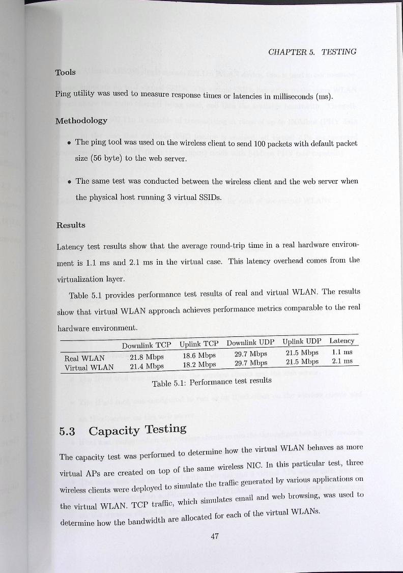
CHAPTER 5. TESTING
Tools
Ping utility was used to measure r ti .:. :. .n. esponse imes or latencies in milliseconds (ms).
Methodology
• The ping tool was used on the wireless client to send 100 packets with default packet
size (56 byte) to the web server.
• The same test was conducted between the wireless client and the web server when
the physical host running 3 virtual SSIDs.
Results
Latency test results show that the average round-trip time in a real hardware environ
ment is 1.1 ms and 2.1 ms in the virtual case. This latency overhead comes from the
virtualization layer. Table 5.1 provides performance test results of real and virtual WLAN. The results
show that virtual WLAN approach achieves performance metrics comparable to the real
hardware environment.
Downlink TCP Uplink TCP Downlink UDP Uplink UDP Latency
Real WLAN Virtual WLAN
21.8 Mbps 21.4 Mbps
18.6 Mbps 18.2 Mbps
29.7 Mbps 29.7 Mbps
21.5 Mbps 21.5 Mbps
1.1 ms 2.1 ms
Table 5.1: Performance test results
5.3 Capacity Testing
Th • ·f d to determine how the virtual WLAN behaves as more
e capacity test was pertorme ,, ed tc of the same wireless NIC. In this particular test, three
virtual APs are create on op O · l t the traffic generated by various applications on
wireless clients were deployed to sua e ,
ff• 1 · 1 simulates email and web browsing, was used to
the virtual WLAN. TCP traffic, which «c . . ll ted for each of the virtual WLANs.
determine how the bandwidth are alloca
47

- CHAPTER 5. TESTING
The Atheros AR9285 single stream 802.lln WLAN device, that is used in our measure
ments, supports up to 4 virtual SSIDs. The virtual SSIDs belonging to the same WLAN
device share the radio channel being used, and thus the available bandwidth. Theoreti
cally, 1-stream 802.111 is capable of transmitting at rates of up to 150Mbps (PHY data
rate). In the case that multiple SSID feature is enabled, all virtual APs are operated
concurrently in none-HT (high throughput) mode with 54Mbps PHY rate capability.
Objective
Determine the total network throughput (Mbps) for each of the virtual WLANs.
Tools
IPerf and JPerf are used to measure the network throughput.
Methodology
• A single virtual AP was created 011 top of the physical WLAN device with WPA2
wireless security.
• The wireless clients were placed at close range to operate on the maximum available
channel bandwidth.
f 1 . t lled on the wireless clients and the web server. • The IPer too was ms a
d . an IPerf client on the wireless clients and • The IPerf tool was configure to run as
an IPerf server on the web server.
. 1 r 1ts to run the throughput test for 120 seconds o [Perf was configured on the wireless cI1eI . . d' la the total throughput in Mbps every 1 second.
in both directions and to lisp! J
:. 4l id 3 virtual APs where each wireless d ·ti 2 virtua an o The same test was conducte wit .
. ] WLAN and throughput tests are running client is connected to a different virtua
:. j( it the same time. on the wireless clients a
48

>
CHAPTER 5. TESTING
Results
Table 5.2 provides capacity test results for virtual WLAN approach. The total down
link/uplink throughput is 19.4/17.2 Mbps with 1 VAP, 19.0/16.9 Mbps with 2 VAP, and
18.9/16.8 Mbps with 3 VAP.
Number of Virtual AP Downlink Throughput (Mbps) Uplink Throughput (Mbps) 1 2 3
19.4 9.56, 9.42
6.42, 6.32, 6.20
17.2 8.52, 8.46
5.64, 5.59, 5.52
Table 5.2: Capacity test results
49

>
Chapter 6
Conclusion
Many enterprises are adopting virtualization to improve server utilization and consolida
tion. However, virtualization can also be used to create a virtualized environment for the
whole network infrastructure. In this thesis, we present a review of the various virtual
ization techniques and open source implementations. These techniques enable enterprise
IT to move forward with virtualization beyond just servers and also virtualize the entire
network infrastructure that were traditionally hardware bound.
However, most of the existing virtualization techniques have focused mostly on wired
network infrastructure. In this thesis, we proposed a virtualization approach to realize
virtual wireless networks by combining wireless LAN virtualization technique with open
source solutions. This approach adds wireless LAN functionally to VM environments and
enables multiple virtual WLANs to operate over a shared physical infrastructure. The
benefits of WLAN infrastructure virtualization, make the implementation of the virtual
WLAN approach an excellent platform for the development and testing of different WLAN
systems and services. The results show that virtual WLAN approach achieves performance
metrics comparable to the native hardware environment.
For the future, it is planned to review the various open source solutions that can
b d t t d h : :t of virtualization on IT infrastructures and services and to
e usec +o study the impac ovide -- solution for enterprises to build their own laas clouds.
provide a complete open source S
50
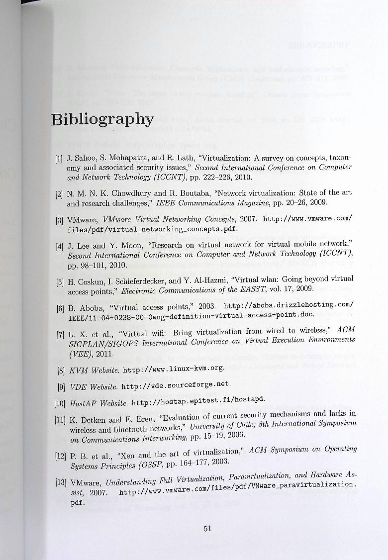
pa
Bibliography
[1] J. Sahoo, S. Mohapatra, and R. Lath, "Virtualization: A survey on concepts, taxon omy and associated security issues," Second International Conference on Computer and Network Technology (ICCNT), pp. 222-226, 2010.
[2] N. M. N. K. Chowdhury and R. Boutaba, "Network virtualization: State of the art and research challenges," IEEE Communications Magazine, pp. 20-26, 2009.
[3] VMware, VMware Virtual Networking Concepts, 2007. http://www.vmware.com/ files/pdf/virtual_networking_concepts.pdf.
[4] J. Lee and Y. Moon, "Research on virtual network for virtual mobile network," Second International Conference on Computer and Network Technology (ICCNT), pp. 98-101, 2010.
[5] H. Coskun, I. Schieferdecker, and Y. Al-Hazmi, "Virtual wlan: Going beyond virtual access points," Electronic Communications of the EASST, vol. 17, 2009.
[6] B. Aboba, "Virtual access points," 2003. http://aboba.drizzlehosting.com/ IEEE/1 1-04-0238-00-0wng-definition-virtual-access-point.doc.
[7] L. X. et al., "Virtual wifi: Bring virtualization from wired to wireless," ACM SIGPLAN/SIGOPS International Conference on Virtual Execution Environments (VEE), 2011.
[8] KVM Website. http://www. linux- kvm. org.
[9] VDE Website. http://vde.sourceforge. net. [10] HostAP Website. http://hostap.epi test. fi/hostapd.
[11]
[2]
[ta]
K. Detken and E. Eren, "Evaluation of current security mechanisms and lacks in wireless and bluetooth networks," University of Chile; 8th International Symposium on Communications Interworking, pp. 15-19, 2006. P. B. et al., "Xen and the art of virtualization," ACM Symposium on Operating Systems Principles (OSSP, pp. 164-177, 2003.
VJ\/1 U d t d. v.ull Virlualization Paravirtualization, and Hardware As- ware, /nlerstanding I'u""" : : 3
sist, 2007. http://www.vmware.com/files/pdf/VMware_paravirtualization. pdf.
51

►
Bibliography
[t] J. Sahoo, S. Mohapatra., and R. Lath, "VirLuali½al.ion: /' ,, 11 ,
omy and associated securi Ly issues," S ccond Inlcrn.11./.i.u n,,.I r 11/" f, and Network Technology (ICCNT), pp. 222-22G, 20 IO
[2] N. M. N. K. Chowdhury and R. Doutaba, "N<'LW•JJ 1, ,i111 1
and research challenges," IEEE Commnn-icoJ:ion:-1 /1J,lff" 1/1'
r i/o
[3] VMware, VMware Virtual Nelworking Conr·r•11/:,, ' f 1rJ, files/pdf/virtual_networking concepts.pd
[4] J. Lee and Y. Moon, Research on virtual ietw Second International Conference on Co ,1 ' •
pp. 98-101, 2010.
[5] H. Coskun, I. Schiefer@decker. and Y A! access points,·' Eleclronic Camm:u
virL ualization. '' 191-Abels.pdf.
8th ACM Workshop
;/www.vmware.com/files/ pdf.
[6] B. Aboba, "Virtual c1c.;(;P' s , IEEE/11-04-0238-CO-~
[7] L. X. ct al., .,, ,. ·· , SIGPLAN /SIGOP (VEE), 20li.
[8] KVM Websit
[9] VDE Wd,·
-irsl Inlernalional Conference on
.org.
,d S. Crosby, "Virtual switching in an era ,I.a Cenler - Conver:qe<l nnd Vi.dual Blhcrncf
5ga.net. 10\ Host/AP
K. /I.ware po.dw,qr; for 1'CI/JJJ ncf:work.'!. http://www.
f.
,.,w. vyatta. corn.
,di.zalion. http: //www, 1:mia. org/sites/default/filcs/
l.r:. http://www. glmrter. org.
Grnncc, ,:The 11i8t. ddinil.io11 of do11tl co111p1tLi11!l;," Nal:iono.l foslif.u.f.c
and 'Technology, vol. 53, no. 6, 2009.
52

- BIBLIOGRAPHY
[4]
(15]
D. Menasce, "Virtualization· Conce t r · I t t · l C · P s, applications, and performance modeling," nernaliona {ompuler Measurement Group (CMG) Conference, pp. 407-414, 2005.
A. Kivity, "Kvm: 'The linux virtual machine monitor ,, Ott L · s · (OLS), pp. 225-230, 2007. ' tawa Janus oymposum
(16] I. Habib, "Virtualization with kvm," Linux Journal, vol. 2008, no. 166, 2008. http: //www.linuxjournal.com/article/9764.
[17] SPICE Website. http://spice-space.org.
[18] A. Binu and G. S. Kumar, "Virtualization techniques: A methodical review of xen and kvm," Communications in Computer and Information Science vol. 190 no. 5 201. " '
[19] J. R. et al., "Bridging the gap between software and hardware techniques for i/ o virtualization," USENIX Annual Technical Conference, 2008.
[20] Xen Website. http://xen.org.
[p21] T. Abels, P. Dhawan, and B. Chandrasekara, "An overview of xen virtualization." http://www.dell.com/downloads/global/power/ps3q05-20050191-Abels.pdf.
[22] B. P. et al., "Extending networking into the virtualization layer," 8th ACM Workshop on Hot Topics in Networks (HotNets-VIII), 2009.
[23] VMware, VMware vNetwork Distributed Switch. http://www.vmware.com/files/ pdf/VMware-vNetwork-Distributed-Switch-DS-EN.pdf.
[24] R. Davoli, "Vde: Virtual distributed ethernet," First International Conference on TRIDENTCOM, 2005.
[25] Open vSwitch Website. http:// openvswi tch. org.
[26] J. Pettit, J. Gross, B. Pfaff, M. Casado, and S. Crosby, "Virtual switching in an era of advanced edges," 2nd Workshop on Data Center - Converged and Virtual Ethernet Switching (DC-CAVES), 2010.
[27] Quagga Website. http://www.quagga.net.
[ A · .rt ckage 1or TCP/IP networks. http://www.
28] Quagga, Quagga: routing so}tware pa J quagga.net/docs/quagga.pdf.
[29] Vyatta Website. http://www.vyatta • com.
[30] SNIA, Storage Virlualization. http://www.snia.org/sites/default/files/ sniavirt. pdf.
[31] GlusterFS Website. http: //www • gluSter · org.
[32] "Tl · t definition of cloud computing," National Institute
P. Moll and T. Grance, 'he nist 1et! 999 of Standards and Technology, vol. 53, no. 0, "
52

- BIBLIOGRAPHY
[3] [34]
[35]
[36]
(37]
OpenNebula Website. http://op bul · enne u a. org.
B. Sotomayor and et al "Virtual . f; t ·» mrastructure mar t' clouds," IEEE Internet Cc ti agemen · 111 private and hybrid . ompu ing, vol. 13, no. 5, 2009.
OpenStack Website. http://openstack.org.
B.J.Carroll, CCNA Wireless: Om·dBi. · · · {Icia /ram Certification Guide. Cisco, 2009.
Cisco Systems, Enterprise Wireless Com :titi P .r II
. pe i ive erJormance Test Results. http: WWW. ClSCO. com.
[38] R J. Bartz, CWTS: Official Study Guide. Sybex, 2009.
[39] M. Anwer and N. Feamster, "Building a fast virtualized data plane with pro grammable hardware," ACM SIGCOMM Workshop on Virtualized Jnfastrnclure Sys tems and Architectures, 2009.
[40] ~CI-SIG, I/0 Virtualizalion (IO V). http://www.pcisig. corn/specifications/ ijov/.
[41] S. Tripathi, N. Droux, and T. Srinivasan, ''Crossbow: From hardware virtualized nics to virtualized networks," ACM SIGCOMM Workshop on Virtualized Ifastructure Systems and Architectures (VISA}, 2009.
[42] D. Raychaudhuri, "Architectures and technologies for the future mobile internet," IEICE Transactions on Communications, pp. 436 441, 2010.
[43] Linux Wireless Website. http://linuxwireless.org.
[44] J. Sachs and S. Baucke, "Virtual radio- a framework for configurable radio networks," Fourth International Wireless Internet Conference (WICON}, 2008.
[45] G. S. et al., "Wireless virtualization on commodity 802.11 hardware," second ACM international workshop on Wireless network testbeds, experimental evaluation and characterization (WinTECH}, 2007.
[46] Z. M. et al., "Resource virtualization with programmable radio processing platform," }th International !CST Conference on Wireless Internet (WICON}, 2008.
[47] R. Chandra and P. Bahl, "Multinet: Connecting to multiple ieee 802.11 networks using a single wireless card," IEEE International Conference on Computer Commu nications (INFOCOM}, 2004.
[48] C. Chereddi, P. Kyasanur, and N. H. Vaidya, "Net-x: A multichannel multi-interface wireless mesh implementation," ACM SIGMOBILE Mobile Computing and Commu nications Review, pp. 84-95, 2007.
[49] A Sl d E B ld. g, fFreemac: Framework for multi-channel mac develop-
· arma an ~ . e m , r 1 • .
t 802 11 h d " A CM workshop on Programmable Routers for Extensible
men on . ar ware, Services of Tomorrow (PRESTO), 2008.
53

>
[50] Y. Al-Hazmi and H. de Meer, "Virtualization of 802.11 interfaces for wireless mesh networks," 18th International Conference on Wireless On-Demand Network Systems and Services (WONS), 2011.
[51] S.-W. Ahn and C. Yoo, "Network interface virtualization in wireless communica tion for multi-streaming service," IEEE 15th International Symposium on Consumer Electronics (ISCE), 2011.
[52] T. Hamaguchi, T. Komata, T. Nagai, and H. Shigeno, "A framework of better de ployment for wlan access point using virtualization technique," IEEE 24th Interna tional Conference on Advanced Information Networking and Applications Workshops (WAINA), p. 968 973, 2010.
[53] WPA Supplicant Website. http: //hostap. epitest.fi/wpa_supplicant.
[54] wpa supplicant Website. http: //hostap. epi test. fi/wpa_supplicant.
[55] G. Aljabari and E. Eren, "Virtualization of wireless lan infrastructures," IEEE 6h International Conference on Intelligent Data Acquisition and Advanced Computing Systems (IDAACS), 2011.
[56] M. Vipin and S. Srikanth, "Analysis of open source drivers for ieee 802.11 wlans," International Conference on Wireless Communication and Sensor Comput ing (ICWCSC), pp. 1-5, 2010.
[s7]
[58]
Atheros, Methodology for Testing Wireless LAN Performance with Chariot, http://www.atheros.com/media/resource/resource_21_file2.pdf.
IPerf Website. http: //sourcef orge .net/projects/iperf •
2003.
54

>
Appendices
55

I»
Appendix A: Virtual WLAIN Platform
This guide explains how to setup a software platform for hosting multiple virtual wireless LAN routers on top of only one physical wireless LAN card. To follow this guide, you need a processor that support hardware-assisted virtualization (Intel VT or AMD- V) and a wireless LAN card-based on Atheros IEEE 802.lln chipset.
As illustrated in the figure below, a single computer is used to host three virtual access point (VAPs) and three virtual routers (VR.s) running Vyatta network OS. Each virtual router has two virtual Ethernet interfaces. One of them is connected to the virtual AP interface and the other to the physical Ethernet interface to access the Internet. Ubuntu is used as a virtual host for setting up the virtual WLAN platform.
Installing Ubuntu 1. Download 32-bit version of Ubuntu 11.04 from http://www.ubuntu. com/ download/
ubuntu/ download.
2. Once you've finished downloading iso file, you'll need to burn a CD or create a USB drive.
3. When the CD is ready, simply put it in your CD drive, restart your computer and follow the instructions that appear on your screen.
Installing Required Packages CPU ts hardware virtualization, run the following
1. To check whether your suppor ' command:
56

egrep ?(vmxlsvm) --color=always /proc/cpuinfo You should see lines with either "vmx" or "svm" highlighted.
2. Install qmu-kvm and libvirt-bin packages. sudo apt-get install qemu-kvm libvirt-bin libvirt-bin provides libvirtd which you need to administer qemu and kvm in stances . The libvirtd-bin package will automatically add your username to the libvirtd group. After the installation, you need to relogin so that your user becomes an effective member of the libvirtd group. The members of this group can run virtual machines.
3. You can test if your install has been successful with the following command:
sudo virsh -c qemu:///system list
If you get an. error message, check if your user is in the libvirtd group with id command.
4. Install virt-manager and virtinst sudo apt-get install virt-manager virtinst
virt -manager is a GUI for managing a virtual machines.
5. Install bridge-utils sudo apt-get install bridge-utils bridge-utils provides a bridge networking for the virtual machines.
6. Install vde2 sudo apt-get install vde2
vde2 provides L2/L3 switching, including spanning-tree protocol and VLANs.
7. Install iw sudo apt-get install iw iw is a CLI for configuring wireless devices
8. Install hostapd sudo apt-get install hostapd
hostapd is a user space daemon for wireless AP.
Configuring Internet Connection 1. To enable a network bridge 011 Internet-facing interface, create a script file setup-internet. s
with the following contents:
57

#!/bin/sh ifconfig eth0 down ifconfig ethO 0.0.0.0 ifconfig ethO up brctl addbr br0 brctl addif br0 eth0 brctl setfd br0 0 #ifconfig brO 10.0.0.254 ifconfig brO up dhclient brO
The dhclient provides a means for configuring a network interfaces using DHCP. If this protocol fails, you can assign an IP address manually with ifconfig command.
2. To make the file executable, run the following command:
chmod +x setup-internet.sh
3. 'Thon execute the file:
./setup-internet.sh
Creating Virtual APs 1. First, it is recommended to disable NetworkManager from starting during boot. You
have to reboot the computer after that:
sudo mv / e_tc/ ini t/network-manager. conf /etc/init/rietwork-manager.conf-disabled
sudo mv /etc/xdg/autostart/nm-applet.desktop /etc/xdg/autostart/nm-applet.desktop.disabled
2. Create the file /etc/hostapd/vap1. conf with the following content:
interface=vap1 bridge=br1 driver=nl80211 logger_syslog=-1 logger_syslog_level=2 logger_stdout=-1 logger_stdout_level=2 ssid=VAP1 hw_mode=g channel=1 auth_algs=l max_num_sta=5 macaddr_acl=O ignore_broadcast_ssid=O wpa=3
58

wpa_pass phrase=12345678 wpa_key_mgmt=WPA-PSK wpa_pairwise=TKIP rsn_pairwise=CCMP
3. To setup the first virtual AP, create a script file setup-vap1. sh with following contents:
#!/bin/sh vde_switch -d -s /var/run/vde1.ctl -p /var/run/vde1.pid -t tap1 -M /var/run/mgmt l brctl addbr br1 brctl addif br1 tap1 brctl setfd br1 0 iw phy phyO interface add vap1 type managed macchanger -r vap1 # ifconfig vapl hw ether 02:20:95:77:b1:72 hostapd -B -P /var/run/vap1.pid /etc/hostapd/vap1.conf brctl addif br1 vap1 ifconfig br1 192.168.1.254 netmask 255.255.255.0 if conf ig br1 up
The macchanger tool generates a MAC address randomly. You may also use ifconfig command to set the MAC address manually.
4. To make the file executable, run the following command:
chmod +x setup-vapl.sh
5. Then execute the file:
./setup-vap1.sh
6. In order to destroy the first virtual AP, create a script file detroy-vap1. sh with following contents:
#!/bin/sh if [ -e /var/run/vde1.pid]; then
kill $(cat /var/run/vde1.pid) fi if [ -e /var/run/vap1.pid]; then
kill $(cat /var/run/vap1.pid) fi if [ -e /sys/class/net/vap1]; then
ifconfig vap1 down iw dev vap1 del
fi if [ -e /sys/class/net/br1 J; then
ifconfig br1 down
59
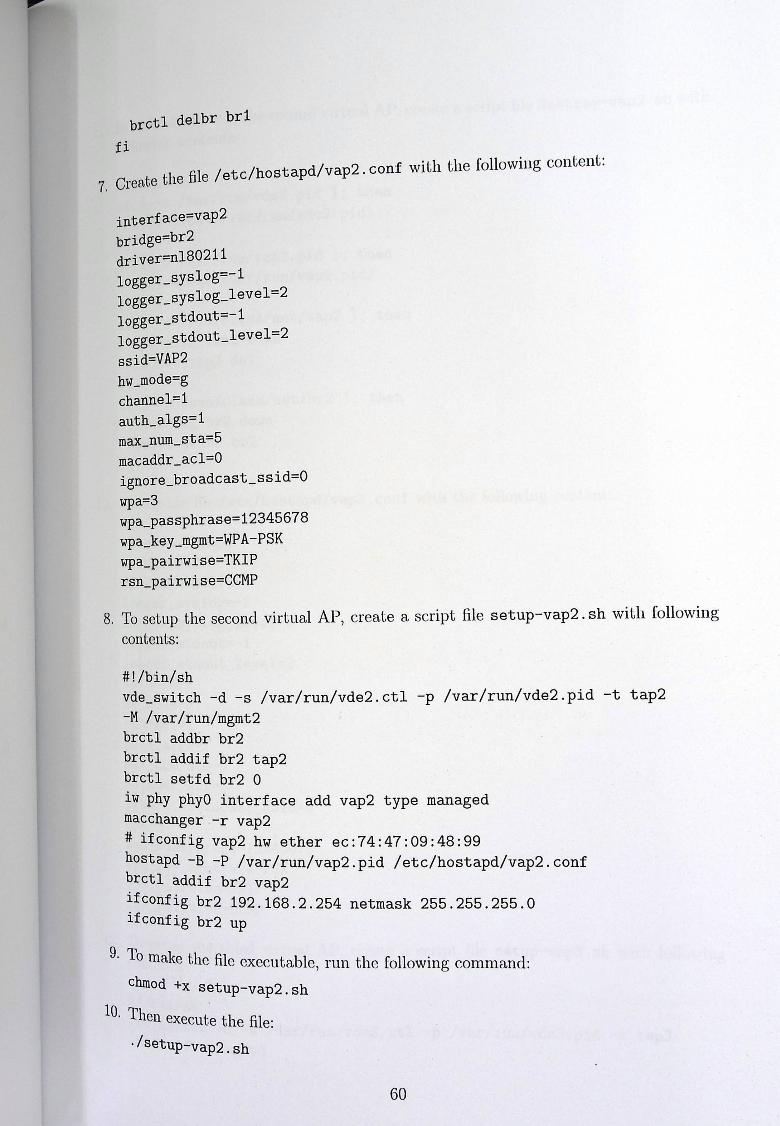
brctl delbr brl fi
. l· fil / etc/hostapd/vap2. conf with the following content: 7, Create the I1e
interface=vap2 bridge=br2 driver=nl80211 logger_syslog=-1 logger_syslog_ level=2 logger_stdout=-1 logger_stdout_level=2 ssid=VAP2 hw_mode=g channel=l auth_algs=1 max_num_sta=5 macaddr_acl=O ignore_broadcast_ssid=O wpa=3 wpa_passphrase=12345678 wpa_key_mgmt=WPA-PSK wpa_pairwise=TKIP rsn_pairwise=CCMP
8. To setup the second virtual AP, create a script file setup-vap2. sh with following contents:
#!/bin/sh vde_switch -d -s /var/run/vde2.ctl -p /var/run/vde2.pid -t tap2 -M /var/run/mgmt2 brctl addbr br2 brctl addif br2 tap2 brctl setfd br2 0 iw phy phyO interface add vap2 type managed macchanger -r vap2 # ifconfig vap2 hw ether ec:74:47:09:48:99 hostapd -B -P /var/run/vap2.pid /etc/hostapd/vap2.conf brctl addif br2 vap2 ifconfig br2 192.168.2.254 netmask 255.255.255.0 ifconfig br2 up
9· To make the file executable, run the following command: chmod +x setup-vap2.sh
10. Ten execute the file: ·/setup-vap2. sh
60
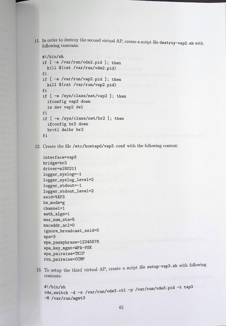
g
11. I order to destroy the second virtual AP creat .· t fil : r eascript le destroy-vap2 sh ith following contents: «st wit
#!/bin/sh if [ -e /var/run/vde2.pid ]; then
kill $(cat /var/run/vde2.pid) fi if [ -e /var/run/vap2.pid]; then
kill $(cat /var/run/vap2.pid) fi if [ -e /sys/class/net/vap2 ]; then
ifconfig vap2 down iw dev vap2 del
fi if [ -e /sys/class/net/br2 ]; then
ifconfig br2 down brctl delbr br2
fi
12. Create the file /etc/hostapd/vap3. conf with the following content:
interface=vap3 bridge=br3 driver=nl80211 logger_syslog=-1 logger_syslog level=2 logger_stdout=-1 logger_stdout_level=2 ssid=VAP3 hw_mode=g channel=! auth_algs=1 max_num_sta=5 macaddr_acl=O ignore_broadcast_ssid=O wpa=3 wpa_ pass phrase=12345678 wpa_key_mgmt=WPA-PSK wpa_pairwise=TKIP rsn_pairwise=CCMP
. t file setup-vap3.sh with following 13. To setup the third virtual AP, create a sCrp
contents:
#!/bin/sh td ·t t 3 vde switch -d -s /var/run/vde3.ctl -p /var/run/vde3.pic ! 5dP
-M /var/run/mgmt3
61

DI
brctl addbr br3 brctl addif br3 tap3 brctl setfd br3 0 iw phy phyO interface add vap3 type managed macchanger -r vap3 # ifconfig vapl hw ether 14:ec:8a:c1:68:4b hostapd -B -P /var/run/vap3.pid /etc/hostapd/vap3.conf brctl addif br3 vap3 ifconfig br3 192.168.3.254 netmask 255.255.255.0 ifconfig br3 up
14. To make the file executable, run the following command: chmod +x setup=-vap3.sh
15. Then execute the file: ./setup-vap3.sh
16. In order to destroy the third virtual AP, create a script file destroy-vap3. sh with following contents:
#!/bin/sh if [ -e /var/run/vde3.pid]; then
kill $(cat /var/run/vde3.pid) fi if [ -e /var/run/vap3.pid ]; then
kill $(cat /var/run/vap3.pid) fi if [ -e /sys/class/net/vap3]; then
ifconfig vap3 down iw dev vap3 del
fi if [ -e /sys/class/net/br3 ]; then
ifconfig br3 down brctl delbr br3
fi
. . . 1 . l t rk interface and the associated op- 17. To display information about the wireless netwo: eration mode run the following command:
' iwconfig
Creating Virtual Routers 3fr http://www.vyatta.org/downloads
1. Download the virtualization iso of Vyatta 6.. from ·P · . . . - er desktop application or virt-install
2. Create the virtual routers using virt-manag command.
62

>
To create a virtual machine with the name VRl r:::i2M . disk image, 2 network devices and Vyatta i"! TB RAM, 1 virtual CPU, 2GB
mage iso, run the followmg command:
sudo virt-install -name VR1 --ram 512 . --vcpus=2 --os-type=linux --hvm --accelerate --location vyatta-livecd-virt_VC6.3-2011.07.21_1386.iso --network=bridge:brO --network=bridge:brl --disk path=/var/lib/libvirt/images/VR1 · : =2 .1Ing,size=. --vnc
To create a virtual machine with the name VR2. 512MB RAM 1 · 1 ·· · 7 4 virtual CPU. 2GB disk image, 2 network devices and Vyatta image iso, ruu th follc » , n e o owmg command:
sudo virt-install -name VR2 --ram 512 --vcpus=2 --os-type=linux --hvm --accelerate --location vyatta-livecd-virt_VC6.3-2011.07.21_1386.iso --network=bridge:brO --network=bridge:br2 --disk path=/var/lib/libvirt/images/VR2.img,size=2 --vnc
To create a virtual machine with the name VR3, 512MB RAM, 1 virtual CPU, 2GB disk image, 2 network devices and Vyatta image iso, run the following command:
sudo virt-install -name VR3 --ram 512 --vcpus=2 --os-type=linux --hvm --accelerate --location vyatta-livecd-virt_VC6.3-2011.07.21_i386.iso --network=bridge:brO --network=bridge:br3 --disk path=/var/lib/libvirt/images/VR3.img,size=2 --vnc
3. After installing Vyatta system on virtual machines, log· on to virtual router with the predefined username "vyatta" and default password "vyatta". The vyatta user has administrator-level privileges and can execute all operating system commands.
4. Configure virtual routers for Internet connection scenario. The router provides DHCP and DNS services to wireless clients. The DNS service on the router forwards the requests to the ISP's DNS server. Masquerade NAT is enabled on Internet-facing interface to provide Internet connectivity to wireless devices.
To configure VRl, issue the following commands:
vyatta@vyatta: "$ configure vyatta@vyatta# set interfaces ethernet ethO address dhcp vyatta@vyatta# set interfaces ethernet eth1 address 192.168.1.1/24 vyatta@vyatta# commit vyatta@vyatta# set service dhcp-server vyatta@vyatta# commit
t ~ · dh er shared-network-name vyata@vyatta# set service icp-serve .68 1 199 ETH1_POOL subnet 192.168.1.0/24 start 192.168.1.100 stop 192.1th.%· vyatta@vyatta# set service dhcp-server shared-network-name ETH1_POOL subnet 192.168.1.0/24 default-router 192.16
8-1·1
63

- vyat ta@vyatta# commit vyatta©vyatta# set service dns forwarding dhcp eth0 vyatta©vyatta# set service dns forwarding listen-on eth1 vyatta©vyatta# set service dhcp-server shared-network-name ETH1_POOL subnet 192.168.1.0/24 dns-server 192.168.1.1 vyatta©vyatta# commit vyatta©vyatta# set service nat rule 10 type masquerade vyatta©vyatta# set service nat rule 10 source address 192.168.1.0/24 vyatta©vyatta# set service nat rule 10 outbound-interface ethO vyatta@vyatta# commit vyatta@vyatta# save vyatta@vyatta# exit
To configure VR2, issue the following commands:
vyatta@vyatta: "$ configure vyatta©vyatta# set interfaces ethernet eth0 address dhcp vyatta©vyatta# set interfaces ethernet eth1 address 192.168.2.1/24
vyatta©vyatta# commit vyatta©vyatta# set service dhcp-server vyatta©vyatta# commit vyat ta@vyatta# set service dhcp-server shared-network-name ETH1_POOL subnet 192.168.2.0/24 start 192.168.2.100 stop 192.168.2.199 vyatta©vyatta# set service dhcp-server shared-network-name ETH1_POOL subnet 192.168.2.0/24 default-router 192.168.2.1 vyatta©vyatta# commit vyatta@vyatta# set service dns forwarding dhcp ethO vyatta@vyatta# set service dns forwarding listen-on ethl vyat ta@vyatta# set service dhcp-server shared-network-name ETH1_P00L subnet 192.168.2.0/24 dns-server 192.168.2.1 vyatta©vyatta# commit vyatta@vyatta# set service nat rule 10 type masquerade vyatta©vyatta# set service nat rule 10 source address 192.168.2.0/24 vyatta©vyatta# set service nat rule 10 outbound-interface ethO
vyatta@vyatta# commit vyatta@vyatta# save vyatta©vyatt# exit
To configure VR3, issue the following commands:
vyatta@vyatta: "$ configure vyat ta@vyatta# set interfaces ethernet ethO address dhcp vyatta@vyatta# set interfaces ethernet ethl address 192.168.3.1/24
vyatta@vyatta# commit vyatta@vyatta# set service dhcp-server vyat ta@vyatta# commit vyatta@vyatta# set service dhcp-server shared-network al©
64

ETH1_POOL subnet 192.168.3.0/24 start 192.168.3.100 stop 192.168.3.199 vyatta@vyatta# set service dhcp-server shared-network-name ETH1_POOL subnet 192.168.3.0/24 default-router 192.168.3.1 vyat ta@vyatta# commit vyatta@vyatta# set service dns forwarding dhcp eth0 vyat ta@vyatta# set service dns forwarding listen-on eth1 vyat ta@vyatta# set service dhcp-server shared-network-name ETH1_POOL subnet 192.168.3.0/24 dns-server 192.168.3.1 vyatta@vyatta# commit vyat ta@vyatta# set service nat rule 10 type masquerade vyat ta@vyatta# set service nat rule 10 source address 192.168.3.0/24 vyatta@vyatta# set service nat rule 10 outbound-interface ethO vyat ta@vyatta# commit vyat ta@vyatta# save
5. Finally, test connecting to VAPl, VAP2, and VAP3 with pre-shared key "12345678°
65
Recommended