
SUNNY FAMILY2011/2012
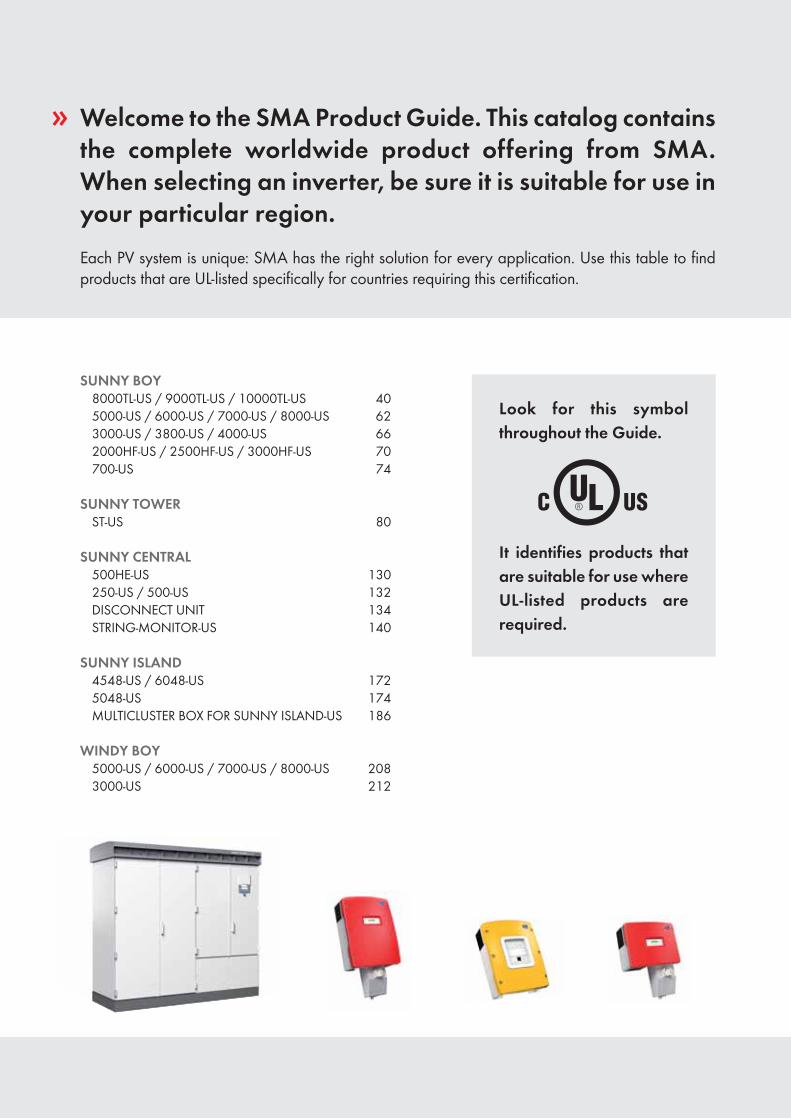
» Welcome to the SMA Product Guide. This catalog contains the complete worldwide product offering from SMA. When selecting an inverter, be sure it is suitable for use in your particular region.Each PV system is unique: SMA has the right solution for every application. Use this table to find products that are UL-listed specifically for countries requiring this certification.
SUNNY BOY8000TL-US / 9000TL-US / 10000TL-US 405000-US / 6000-US / 7000-US / 8000-US 623000-US / 3800-US / 4000-US 662000HF-US / 2500HF-US / 3000HF-US 70700-US 74
SUNNY TOWERST-US 80
SUNNY CENTRAL500HE-US 130250-US / 500-US 132DISCONNECT UNIT 134STRING-MONITOR-US 140
SUNNY ISLAND4548-US / 6048-US 1725048-US 174MULTICLUSTER BOX FOR SUNNY ISLAND-US 186
WINDY BOY5000-US / 6000-US / 7000-US / 8000-US 2083000-US 212
Look for this symbol throughout the Guide.
It identifies products that are suitable for use where UL-listed products are required.
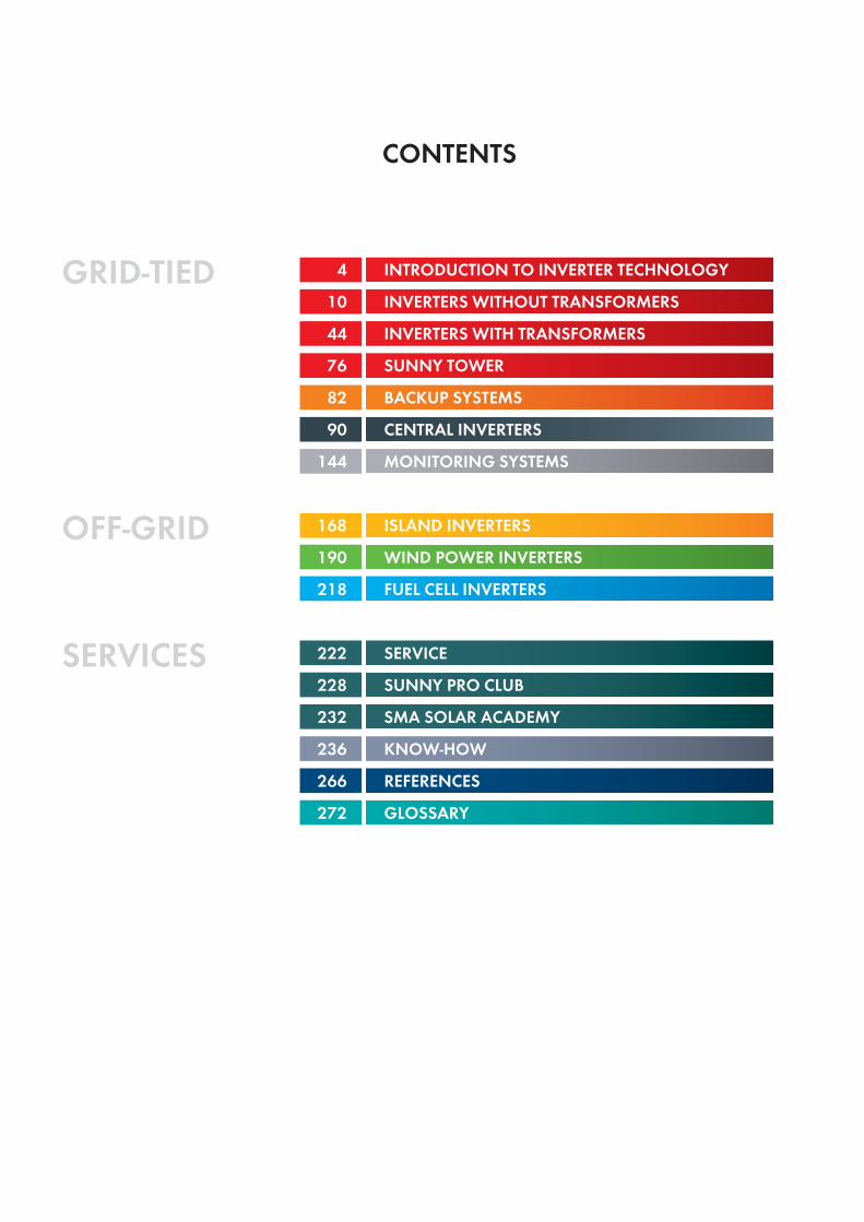
CONTENTS
SERVICES
GRID-TIED
OFF-GRID
41044768290
144
168190218
222228232236266272
INTRODUCTION TO INVERTER TECHNOLOGYINVERTERS WITHOUT TRANSFORMERSINVERTERS WITH TRANSFORMERSSUNNY TOWERBACKUP SYSTEMSCENTRAL INVERTERSMONITORING SYSTEMS
ISLAND INVERTERSWIND POWER INVERTERSFUEL CELL INVERTERS
SERVICESUNNY PRO CLUBSMA SOLAR ACADEMYKNOW-HOWREFERENCESGLOSSARY
4
5
Solar inverters from SMA:Innovative technology and unmatched quality
The first solar inverter was one of ours. To-day, SMA solar inverters are the product of almost 30 years of experience. With 7.9 gigawatts of installed PV power, we play a leading role in the success of photovoltaics. An important reason for this is that we invest substantially in research and development. At our company headquarters in Niestetal, Germany, over 500 developers are work-ing on making our devices even more user-friendly and further cost-effective.
Investment security and fast amortization
Durability and economic viability are impor-tant criteria in selecting an inverter. With a service life of over 20 years and greater than 98 percent efficiency, SMA products set the standard for the industry. The key to our suc-cess-—the combination of the latest technolo-gies and modern production processes. The enhanced OptiTrac Global Peak op-eration control, the asymmetrical Optiflex multistring topology and the Optiprotect security concept ensure the best possible performance, regardless of the weather.
Flexible plant design
PV plants are just as individual as the build-ings and surfaces on which they are in-stalled. A broad range of products allows for the selection of the right inverter for any PV module and ensures the best energy harvest possible. SMA offers an inverter for any requirement, making the perfect plant design possible. Our inverters can be in-stalled indoors as well as outdoors.
Safe installation
With the SMA Grid Guard and Electronic Solar Switch (ESS), SMA provides the most reliable safety systems on the market. For countries that require UL certification, the design of these safety technologies differs slightly (see page 208). The standardized SUNCLIX® DC plug system, the newly de-veloped communication unit Quick Module or the SMA Plug-in Grounding kit make in-stallation even easier and faster.
Simple control
All SMA inverters can be combined with a wide range of PV plant monitoring compo-nents such as the Sunny Beam with Blue-tooth® for compact monitoring, the Sunny WebBox for online diagnosis and mainte-nance, and the Sunny Portal—the world’s largest online portal for PV plant monitoring and administration.
Einführung Wechselrichtertechnik
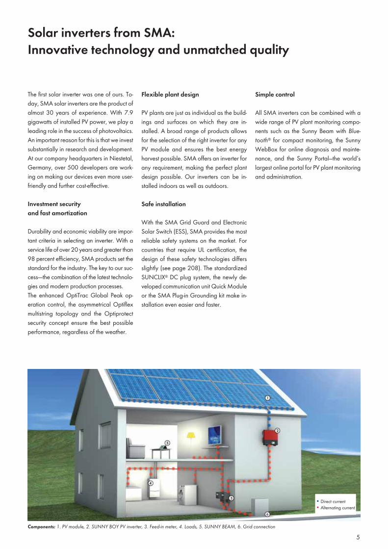
Components: 1. PV module, 2. SUNNY BOY PV inverter, 3. Feed-in meter, 4. Loads, 5. SUNNY BEAM, 6. Grid connection
Direct currentAlternating current
6
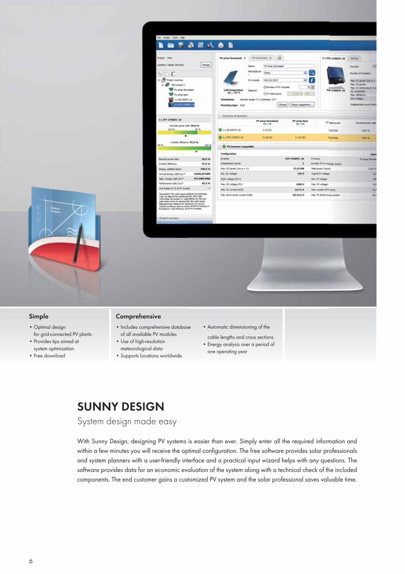
SUNNY DESIGN System design made easyWith Sunny Design, designing PV systems is easier than ever. Simply enter all the required information and within a few minutes you will receive the optimal configuration. The free software provides solar professionals and system planners with a user-friendly interface and a practical input wizard helps with any questions. The software provides data for an economic evaluation of the system along with a technical check of the included components. The end customer gains a customized PV system and the solar professional saves valuable time.
Simple• Optimal design
for grid-connected PV plants• Provides tips aimed at
system optimization• Free download
Comprehensive• Includes comprehensive database
of all available PV modules• Use of high-resolution
meteorological data• Supports locations worldwide
• Automatic dimensioning of the cable lengths and cross sections
• Energy analysis over a period of one operating year
7
Sunny Design contains important SMA in-verter data as well as specifications on all currently available PV modules. It is easy to use and guides the planner through the entire design process. This saves time and allows different configuration options to be simulated without the need for com-plicated calculations. Sunny Design auto-matically calculates the design values and comes up with a comprehensive result for all design variants.
First, critical operating conditions are identi-fied. This ensures that the planner is notified of any deviations from the standard design. Although this notification does not necessar-ily mean that the design is not permissible, it serves to indicate that a thorough check is required to see whether this operating state is optimal for the current configuration (e.g. array voltage too low).
Sunny Design enables the system designer to fully concentrate on what plant designing is all about. The software helps to estimate the yield and investment cost implications of the most important performance param-eters, creating a tailor-made system for the customer.
Additionally, a realistic operation evalu-ation is performed over a calendar year utilizing an integrated meteorological data-base. Although a precise yield forecast can-not be expected from Sunny Design (further simulation programs with complex variable analysis is necessary for this), Sunny De-sign can determine the yield differences be-tween various designs, including a techni-cal performance verification. Not only can the best system design be found, it can also be evaluated for cost-effectiveness.
Lastly, a technical assessment of the system design is clearly illustrated in an individu-ally customized results report. As a printed document or an electronic PDF file, this sum-mary is the ideal supplement to any offer.
Free download at www.SMA.de/SunnyDesign
Introduction to Inverter Technology
Database of currentPV modules
Database of all SMA invertersUse of real, high-resolution meteorological data
Provides tips aimed at plant optimization
Generation of design proposals
Automatic online updatesResults report with individual layout for integration into plant quotes
Worldwide support
System Requirements
Supported operating systemsWindows XP SP3*Windows Vista SP2*Windows 7**with .Net Framework 4.0
Hardware (minimum requirements)Intel Pentium 1 GHz1 GB RAM100 MB (free hard drive space)1024 x 768 pixels / 256 colors
8
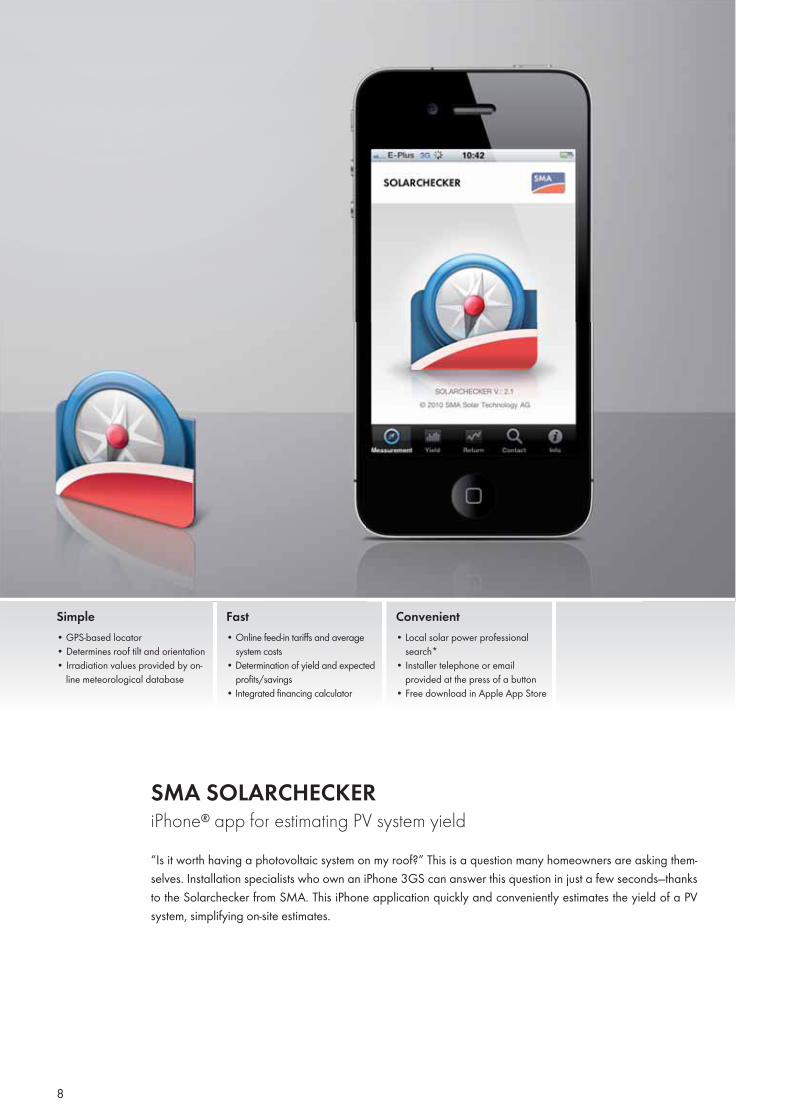
SMA SOLARCHECKERiPhone® app for estimating PV system yield“Is it worth having a photovoltaic system on my roof?” This is a question many homeowners are asking them-selves. Installation specialists who own an iPhone 3GS can answer this question in just a few seconds—thanks to the Solarchecker from SMA. This iPhone application quickly and conveniently estimates the yield of a PV system, simplifying on-site estimates.
Simple• GPS-based locator• Determines roof tilt and orientation• Irradiation values provided by on-
line meteorological database
Fast• Online feed-in tariffs and average
system costs• Determination of yield and expected
profits/savings• Integrated financing calculator
Convenient • Local solar power professional
search*• Installer telephone or email
provided at the press of a button• Free download in Apple App Store
9
Profi t estimate at the press of a button
For locations with a feed-in tariff, simply type in the current feed-in tariff per kilo-watt hour and the expected fi nancing costs and the application will estimate the pos-sible profi ts that can be generated by the planned PV system.
Free download atwww.apple.com/itunes
Traditionally, solar system engineers need-ed a long time before they could provide potential customers with an initial yield estimate. Now, technicians can instantly calculate this estimate using an iPhone and the SMA Solarchecker. This mobile device features integrated sensors that al-low it to automatically determine the loca-tion, orientation and tilt of a roof. The SMA Solarchecker application uses this data, along with custom information such as sys-tem size and fi nancing costs, to estimate the power yield and profi ts of a potential PV system. Although the estimate does not replace the fi nal, detailed planning of the system, it saves valuable time and quickly convinces customers of the benefi ts of these cost-effective and environmentally friendly projects.
The iPhone as a solar power planner
The SMA Solarchecker fi nds the operator’s current location using the iPhone’s GPS tracker. Using these values, the application determines the site’s potential solar irradia-tion, which is derived from a GPS-based weather database. Using the phone’s magnetic compass, the application then measures to what degree the roof deviates from the ideal south-facing orientation. The device also determines the possible angle of the solar array using the tilt sensor. The SMA Solarchecker then uses these values
to determine the specifi c yield of a PV sys-tem, i.e. the number of kilowatt hours pro-duced per kW of power.
Calculating energy yield with the Solarchecker
To determine the energy yield, the planned power of the PV array must be calculated fi rst. The SMA Solarchecker of-fers two ways to complete this step. The user can enter power directly in kWp or input the number of square meters of the planned PV system. In the latter case, the application automatically converts the roof area into power. Of course, the ap-plication takes into account the previously specifi ed PV module type.
The SMA Solarchecker calculates the an-nual energy yield of the PV system by mul-tiplying the specifi c yield of the roof area with the planned peak power. Long-term estimates, e.g. over 20 years, are also possible. For degradation, the SMA So-larchecker uses a value of 0.2 percent per year. A more precise calculation can be made by adjusting this value.
Introduction to Inverter Technology
Automatic determination of position, inclination and orientation
Manual input of roof area, module type and maintenance costs
Use of approved irradiation data
Integrated financing calculator
Integrated solar power professional search*
Data transfer via automatically generated e-mail
* All members of the Sunny PRO Club are included in SMA’s solar power professional search.
Languages: German, English, Italian, Spanish, French
Yield and profit estimate at the press of a button
Important Information
Because the returns and profits are depend-ent on the estimate of the specific yearly yield, they both carry some uncertainty. SMA is not liable for lower actual yields, which can be caused by other factors such as shading, dirt or otherwise compromised modules. For more precise yield calcula-tions, SMA recommends consulting a quali-fied technician or system planner.
10
INVERTERS WITHOUT TRANSFORMERS
11
12
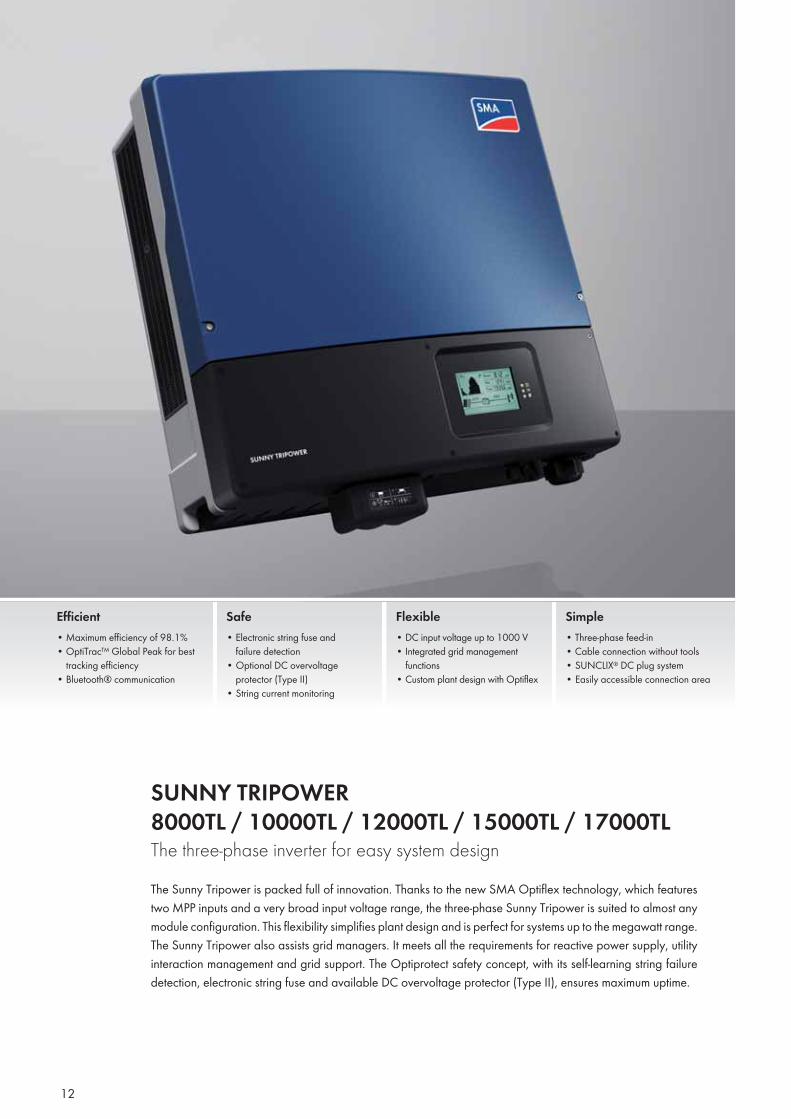
SUNNY TRIPOWER 8000TL / 10000TL / 12000TL / 15000TL / 17000TL The three-phase inverter for easy system designThe Sunny Tripower is packed full of innovation. Thanks to the new SMA Optiflex technology, which features two MPP inputs and a very broad input voltage range, the three-phase Sunny Tripower is suited to almost any module configuration. This flexibility simplifies plant design and is perfect for systems up to the megawatt range. The Sunny Tripower also assists grid managers. It meets all the requirements for reactive power supply, utility interaction management and grid support. The Optiprotect safety concept, with its self-learning string failure detection, electronic string fuse and available DC overvoltage protector (Type II), ensures maximum uptime.
Efficient• Maximum efficiency of 98.1%• OptiTrac™ Global Peak for best
tracking efficiency• Bluetooth® communication
Safe• Electronic string fuse and
failure detection• Optional DC overvoltage
protector (Type II)• String current monitoring
Flexible• DC input voltage up to 1000 V• Integrated grid management
functions• Custom plant design with Optiflex
Simple• Three-phase feed-in• Cable connection without tools• SUNCLIX® DC plug system • Easily accessible connection area
13
Inverters without Transformers
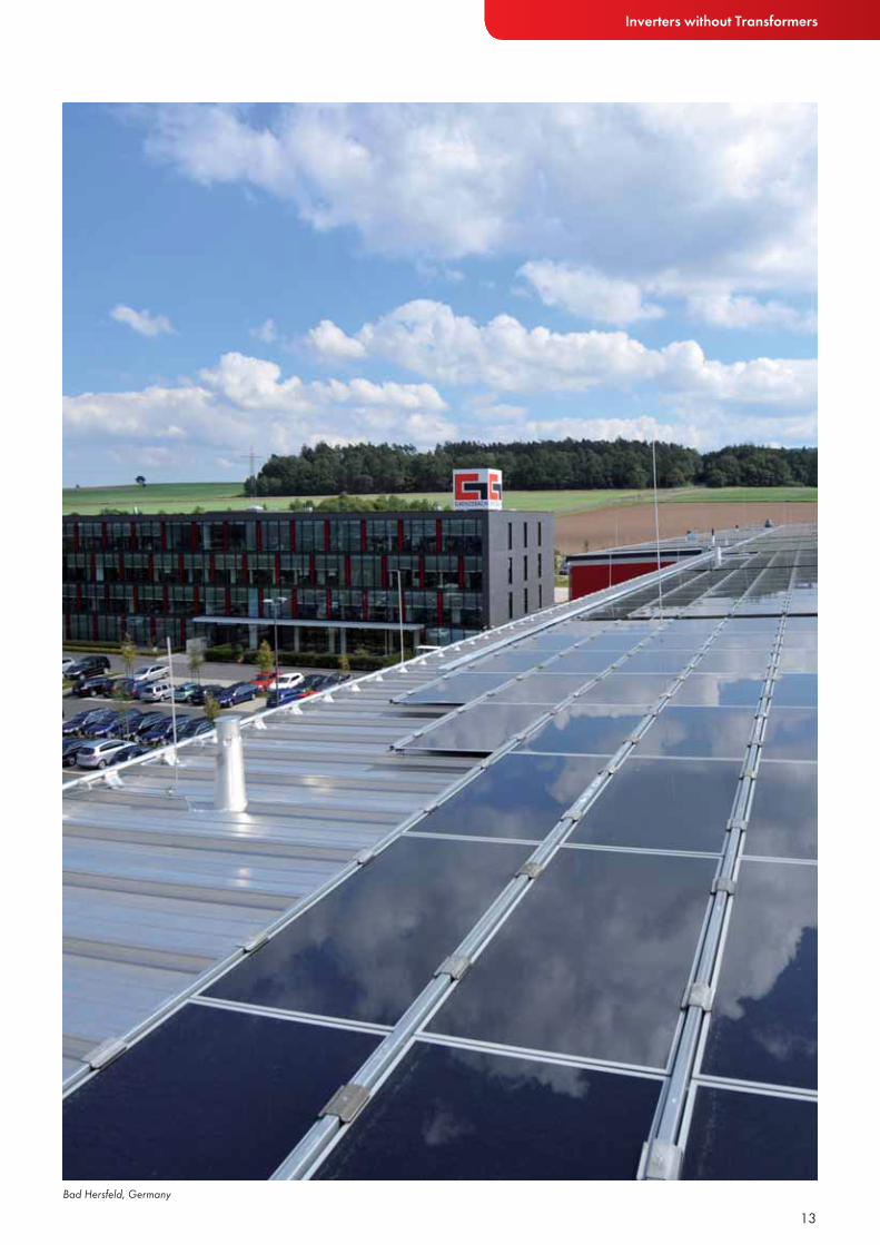
Bad Hersfeld, Germany
14
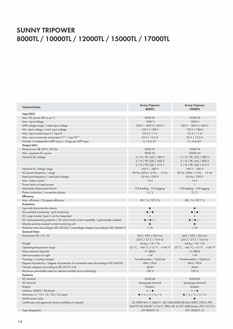
SUNNY TRIPOWER 8000TL / 10000TL / 12000TL / 15000TL / 17000TL
Input (DC)Max. DC power (@ cos ϕ=1)Max. input voltageMPP voltage range / rated input voltageMin. input voltage / initial input voltageMax. input current input A / input BMax. input current per string input A** / input B**Number of independent MPP inputs / strings per MPP inputOutput (AC)Rated power (@ 230 V, 50 Hz)Max. apparent AC powerNominal AC voltage
Nominal AC voltage rangeAC power frequency / rangeRated grid frequency / rated grid voltageMax. output currentPower factor at rated powerAdjustable displacement factorPhase conductors / connection phasesEffi ciencyMax. effi ciency / European effi ciencyProtectionInput-side disconnection deviceGround-fault monitoring / grid monitoringDC surge arrester Type II, can be integratedDC reverse-polarity protection / AC short-circuit current capability / galvanically isolatedAll-pole sensitive residual current monitoring unitProtection class (according to IEC 62103) / overvoltage category (according to IEC 60664-1)General DataDimensions (W / H / D)
WeightOperating temperature rangeNoise emission (typical)Self-consumption at nightTopology / cooling conceptDegree of protection / degree of protection of connection area (according to IEC 60529)Climatic category (according to IEC 60721-3-4)Maximum permissible value for relative humidity (non-condensing)FeaturesDC terminalAC terminalDisplayInterface: RS485 / BluetoothWarranty: 5 / 10 / 15 / 20 / 25 yearsMulti-function relayCertifi cates and approvals (more available on request)
Type designation
Technical Data Sunny Tripower8000TL
Sunny Tripower10000TL
10200 W1000 V
320 V – 800 V / 600 V150 V / 188 V22 A / 11 A
33 A / 12.5 A2 / A:4; B:1
10000 W10000 VA
3 / N / PE; 220 / 380 V3 / N / PE; 230 / 400 V3 / N / PE; 240 / 415 V
160 V – 280 V50 Hz, 60Hz / -6 Hz … +5 Hz
50 Hz / 230 V16 A
10.8 leading… 0.8 lagging
3 / 3
98.1 % / 97.7 %
●● / ●
○● / ● / —
●I / III
665 / 690 / 265 mm (26.2 / 27.2 / 10.4 in)
64 kg / 141.1 lb-25 °C … +60 °C / -13 °F … +140 °F
51 dB(A)1 W
Transformerless / OptiCoolIP65 / IP54
4K4H100 %
SUNCLIXSpring-type terminal
Graphic○ / ●
● / ○ / ○ / ○ / ○●
8200 W1000 V
320 V – 800 V / 600 V150 V / 188 V22 A / 11 A
33 A / 12.5 A2 / A:4; B:1
8000 W8000 VA
3 / N / PE; 220 / 380 V3 / N / PE; 230 / 400 V3 / N / PE; 240 / 415 V
160 V – 280 V50 Hz, 60Hz / -6 Hz … +5 Hz
50 Hz / 230 V16 A
10.8 leading… 0.8 lagging
3 / 3
98.1 % / 97.5 %
●● / ●
○● / ● / —
●I / III
665 / 690 / 265 mm (26.2 / 27.2 / 10.4 in)
64 kg / 141.1 lb-25 °C … +60 °C / -13 °F … +140 °F
51 dB(A)1 W
Transformerless / OptiCoolIP65 / IP54
4K4H100 %
SUNCLIXSpring-type terminal
Graphic○ / ●
● / ○ / ○ / ○ / ○●
CE, VDE0126-1-1, G83/1-1, RD 1663/2000, RD 661/2007, G59/2, PPC, AS4777, EN 50438*, C10/11, PPDS, IEC 61727, ENEL-Guida, UTE C15-712-1
STP 8000TL-10 STP 10000TL-10
15
Inverters without Transformers
Accessories
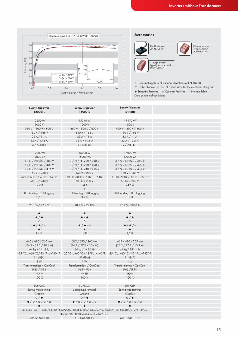
Sunny Tripower12000TL
Sunny Tripower15000TL
Sunny Tripower17000TL
● Standard features ○ Optional features — Not availableData at nominal conditions
RS485 interface DM-485CB-10
DC surge arrester (Type II), input ADCSPD KIT1-10
DC surge arrester (Type II), inputs A and BDCSPD KIT2-10
* Does not apply to all national deviations of EN 50438 ** To be observed in case of a short circuit in the electronic string fuse
12250 W1000 V
380 V – 800 V / 600 V150 V / 188 V22 A / 11 A
33 A / 12.5 A2 / A:4; B:1
12000 W12000 VA
3 / N / PE; 220 / 380 V3 / N / PE; 230 / 400 V3 / N / PE; 240 / 415 V
160 V – 280 V50 Hz, 60Hz / -6 Hz … +5 Hz
50 Hz / 230 V19.2 A
10.8 leading… 0.8 lagging
3 / 3
98.1 % / 97.7 %
●● / ●
○● / ● / —
●I / III
665 / 690 / 265 mm (26.2 / 27.2 / 10.4 in)
64 kg / 141.1 lb-25 °C … +60 °C / -13 °F … +140 °F
51 dB(A)1 W
Transformerless / OptiCoolIP65 / IP54
4K4H100 %
SUNCLIXSpring-type terminal
Graphic○ / ●
● / ○ / ○ / ○ / ○●
15340 W1000 V
360 V – 800 V / 600 V150 V / 188 V33 A / 11 A
33 A / 12.5 A2 / A:5; B:1
15000 W15000 VA
3 / N / PE; 220 / 380 V3 / N / PE; 230 / 400 V3 / N / PE; 240 / 415 V
160 V – 280 V50 Hz, 60Hz / -6 Hz … +5 Hz
50 Hz / 230 V24 A
10.8 leading… 0.8 lagging
3 / 3
98.2 % / 97.8 %
●● / ●
○● / ● / —
●I / III
665 / 690 / 265 mm (26.2 / 27.2 / 10.4 in)
64 kg / 141.1 lb-25 °C … +60 °C / -13 °F … +140 °F
51 dB(A)1 W
Transformerless / OptiCoolIP65 / IP54
4K4H100 %
SUNCLIXSpring-type terminal
Graphic○ / ●
● / ○ / ○ / ○ / ○●
17410 W1000 V
400 V – 800 V / 600 V150 V / 188 V33 A / 11 A
33 A / 12.5 A2 / A:5; B:1
17000 W17000 VA
3 / N / PE; 220 / 380 V3 / N / PE; 230 / 400 V3 / N / PE; 240 / 415 V
160 V – 280 V50 Hz, 60Hz / -6 Hz … +5 Hz
50 Hz / 230 V24.6 A
10.8 leading… 0.8 lagging
3 / 3
98.2 % / 97.8 %
●● / ●
○● / ● / —
●I / III
665 / 690 / 265 mm (26.2 / 27.2 / 10.4 in)
64 kg / 141.1 lb-25 °C … +60 °C / -13 °F … +140 °F
51 dB(A)1 W
Transformerless / OptiCoolIP65 / IP54
4K4H100 %
SUNCLIXSpring-type terminal
Graphic○ / ●
● / ○ / ○ / ○ / ○●
CE, VDE0126-1-1, G83/1-1, RD 1663/2000, RD 661/2007, G59/2, PPC, AS4777, EN 50438*, C10/11, PPDS, IEC 61727, ENEL-Guida, UTE C15-712-1
STP 12000TL-10 STP 15000TL-10 STP 17000TL-10
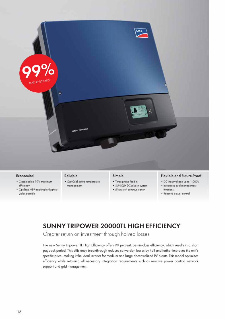
99%MAX. EFFICIENCY
16
SUNNY TRIPOWER 20000TL HIGH EFFICIENCY Greater return on investment through halved lossesThe new Sunny Tripower TL High Effi ciency offers 99 percent, best-in-class effi ciency, which results in a short payback period. This effi ciency breakthrough reduces conversion losses by half and further improves the unit’s specifi c price—making it the ideal inverter for medium and large decentralized PV plants. This model optimizes effi ciency while retaining all necessary integration requirements such as reactive power control, network support and grid management.
Economical• Class-leading 99% maximum effi ciency• OptiTrac MPP tracking for highest yields possible
Reliable• OptiCool active temperature management
Simple• Three-phase feed-in• SUNCLIX DC plug-in system• Bluetooth® communication
Flexible and Future-Proof• DC input voltage up to 1,000V• Integrated grid management functions• Reactive power control
17
Inverters without Transformers
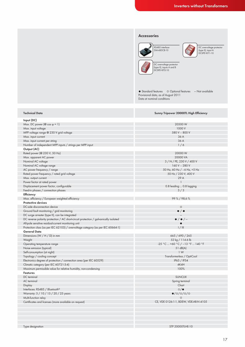
Accessories
● Standard features ○ Optional features — Not availableProvisional data, as of August 2011 Data at nominal conditions
RS485 interface DM-485CB-10
DC overvoltage protector (type II), input ADCSPD KIT1-10
DC overvoltage protector (type II), inputs A and BDCSPD KIT2-10
Technical Data Sunny Tripower 20000TL High Efficiency
Input (DC)Max. DC power (@ cos ϕ = 1) 20500 WMax. input voltage 1000 VMPP voltage range @ 230 V grid voltage 580 V – 800 VMax. input current 36 AMax. input current per string 36 ANumber of independent MPP inputs / strings per MPP input 1 / 6Output (AC)Rated power (@ 230 V, 50 Hz) 20000 WMax. apparent AC power 20000 VANominal AC voltage 3 / N / PE, 230 V / 400 VNominal AC voltage range 160 V – 280 VAC power frequency / range 50 Hz, 60 Hz / –6 Hz, +5 HzRated power frequency / rated grid voltage 50 Hz / 230 V, 400 VMax. output current 29 APower factor at rated power 1Displacement power factor, confi gurable 0.8 leading ... 0.8 laggingFeed-in phases / connection phases 3 / 3Effi ciencyMax. effi ciency / European weighted effi ciency 99 % / 98,6 %Protective devicesDC-side disconnection device ○Ground fault monitoring / grid monitoring ● / ●DC surge arrester (type II), can be integrated —DC reverse polarity protection / AC short-circuit protection / galvanically isolated ● / ● / —All-pole sensitive residual-current monitoring unit ●Protection class (as per IEC 62103) / overvoltage category (as per IEC 60664-1) I / IIIGeneral DataDimensions (W / H / D) in mm 665 / 690 / 265Weight 52 kg / 114.6 lbOperating temperature range -25 °C ... +60 °C / –13 °F ... 140 °FNoise emission (typical) 51 dB(A)Self-consumption (at night) 1 WTopology / cooling concept Transformerless / OptiCoolElectronics degree of protection / connection area (per IEC 60529) IP65 / IP54Climatic category (per IEC 60721-3-4) 4K4HMaximum permissible value for relative humidity, non-condensing 100%FeaturesDC terminal SUNCLIXAC terminal Spring terminalDisplay ChartInterfaces: RS485 / Bluetooth® ○/●Warranty: 5 / 10 / 15 / 20 / 25 years ●/○/○/○/○Multi-function relay ○Certificates and licenses (more available on request) CE, VDE 0126-1-1, BDEW, VDE-AR-N 4105
Type designation STP 20000TLHE-10

18
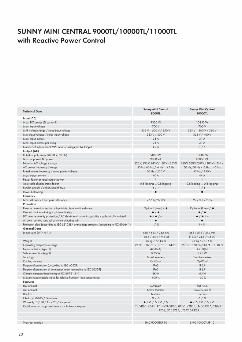
SUNNY MINI CENTRAL 9000TL / 10000TL / 11000TL with Reactive Power ControlOptimum grid integration with reactive power supplySunny Mini Central inverters with reactive power control are the ideal solution when utility companies require reactive power supply. They can be used for PV plant designs which specify the displacement factor cos ϕ and the corresponding percentage of reactive power. Large PV power plants can now make optimum use of distri-bution capacities, which significantly contributes to the continued penetration of renewable energy on the grid.
Flexible• Integrated grid management with reactive power control
High Yields• Maximum efficiency of 97.7%• Transformerless, H5 topology• OptiCool active temperature management
Reliable• Pluggable SMA Power Balancer for three-phase power • Integrated ESS DC switch disconnect• Monitored string fuses
Simple• SUNCLUX DC plug-in system speeds installation
19
Inverters without Transformers
Thiva, Greece
20
SUNNY MINI CENTRAL 9000TL/10000TL/11000TLwith Reactive Power Control
Input (DC)Max. DC power (@ cos ϕ=1)Max. input voltageMPP voltage range / rated input voltageMin. input voltage / initial input voltageMax. input currentMax. input current per stringNumber of independent MPP inputs / strings per MPP inputOutput (AC)Rated output power (@230 V, 50 Hz)Max. apparent AC powerNominal AC voltage / rangeAC power frequency / rangeRated power frequency / rated power voltageMax. output currentPower factor at rated output powerAdjustable displacement factorFeed-in phases / connection phasesPower balancingEffi ciencyMax. effi ciency / European effi ciencyProtectionReverse current protection / input-side disconnection deviceGround fault monitoring / grid monitoringDC reverse-polarity protection / AC short-circuit current capability / galvanically isolatedAll-pole sensitive residual current monitoring unitProtection class (according to IEC 62103) / overvoltage category (according to IEC 60664-1)General DataDimensions (W / H / D)
WeightOperating temperature rangeNoise emission (typical)Self-consumption (night)TopologyCooling conceptDegree of protection (according to IEC 60529)Degree of protection of connection area (according to IEC 60529)Climatic category (according to IEC 60721-3-4)Maximum permissible value for relative humidity (non-condensing)FeaturesDC terminalAC terminalDisplayInterface: RS485 / BluetoothWarranty: 5 / 10 / 15 / 20 / 25 yearsCertifi cates and approvals (more available on request)
Type designation
Technical Data Sunny Mini Central9000TL
Sunny Mini Central10000TL
9300 W700 V
333 V – 500 V / 350 V333 V / 400 V
28 A28 A1 / 5
9000 W9000 VA
220 V, 230 V, 240 V / 180 V – 265 V50 Hz, 60 Hz / -6 Hz … +5 Hz
50 Hz / 230 V40 A
10.8 leading … 0.8 lagging
1 / 1●
97.7 % / 97.3 %
Optional (fuses) / ●● / ●
● / ● / —●
I / III
468 / 613 / 242 mm (18.4 / 24.1 / 9.5 in)
35 kg / 77.16 lb-25 °C … +60 °C / -13 °F … +140 °F
42 dB(A)0.25 W
TransformerlessOptiCool
IP65IP65
4K4H100 %
SUNCLIXScrew terminal
Text line○ / ○
● / ○ / ○ / ○ / ○CE, VDE0126-1-1, RD 1663/2000, RD 661/2007, EN 50438*, C10/11,
PPDS, EC 61727, UTE C15-712-1
SMC 9000TLRP-10
10350 W700 V
333 V – 500 V / 350 V333 V / 400 V
31 A31 A1 / 5
10000 W10000 VA
220 V, 230 V, 240 V / 180 V – 265 V50 Hz, 60 Hz / -6 Hz … +5 Hz
50 Hz / 230 V44 A
10.8 leading … 0.8 lagging
1 / 1●
97.7 % / 97.2 %
Optional (fuses) / ●● / ●
● / ● / —●
I / III
468 / 613 / 242 mm (18.4 / 24.1 / 9.5 in)
35 kg / 77.16 lb-25 °C … +60 °C / -13 °F … +140 °F
45 dB(A)0.25 W
TransformerlessOptiCool
IP65IP65
4K4H100 %
SUNCLIXScrew terminal
Text line○ / ○
● / ○ / ○ / ○ / ○
SMC 10000TLRP-10

21
Inverters without Transformers
Accessories
Input (DC)Max. DC power (@ cos ϕ=1)Max. input voltageMPP voltage range / rated input voltageMin. input voltage / initial input voltageMax. input currentMax. input current per stringNumber of independent MPP inputs / strings per MPP inputOutput (AC)Rated output power (@230 V, 50 Hz)Max. apparent AC powerNominal AC voltage / rangeAC power frequency / rangeRated power frequency / rated power voltageMax. output currentPower factor at rated output powerAdjustable displacement factorFeed-in phases / connection phasesPower balancingEffi ciencyMax. effi ciency / European effi ciencyProtectionReverse current protection / input-side disconnection deviceGround fault monitoring / grid monitoringDC reverse-polarity protection / AC short-circuit current capability / galvanically isolatedAll-pole sensitive residual current monitoring unitProtection class (according to IEC 62103) / overvoltage category (according to IEC 60664-1)General DataDimensions (W / H / D)
WeightOperating temperature rangeNoise emission (typical)Self-consumption (night)TopologyCooling conceptDegree of protection (according to IEC 60529)Degree of protection of connection area (according to IEC 60529)Climatic category (according to IEC 60721-3-4)Maximum permissible value for relative humidity (non-condensing)FeaturesDC terminalAC terminalDisplayInterface: RS485 / BluetoothWarranty: 5 / 10 / 15 / 20 / 25 yearsCertifi cates and approvals (more available on request)
Type designation
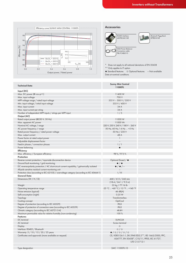
Technical Data Sunny Mini Central11000TL
● Standard features ○ Optional features — Not availableData at nominal conditions
RS485 interface 485PB-SMC-NR
Bluetooth Piggy-BackBTPBINV-NR
SMA Power Balancer Connection cable PBL-YCABLE-10
* Does not apply to all national appendixes to EN 50438
11400 W700 V
333 V – 500 V / 350 V333 V / 400 V
34 A34 A1 / 5
11000 W11000 VA
220 V, 230 V, 240 V / 180 V – 265 V50 Hz, 60 Hz / -6 Hz … +5 Hz
50 Hz / 230 V48 A
10.8 leading … 0.8 lagging
1 / 1●
97.7 % / 97.2 %
Optional (fuses) / ●● / ●
● / ● / —●
I / III
468 / 613 / 242 mm (18.4 / 24.1 / 9.5 in)
35 kg / 77.16 lb-25 °C … +60 °C / -13 °F … +140 °F
46 dB(A)0.25 W
TransformerlessOptiCool
IP65IP65
4K4H100 %
SUNCLIXScrew terminal
Text line○ / ○
● / ○ / ○ / ○ / ○CE, VDE0126-1-1, RD 1663/2000 , RD 661/2007, EN 50438*,
C10/11, PPDS, IEC 61727, UTE C15-712-1
SMC 11000TLRP-10

22
SUNNY MINI CENTRAL 9000TL / 10000TL / 11000TL Precise system design for maximum yieldsThe Sunny Mini Central simplifies the planning of medium and large PV plants, from 27 kWp up to the mega-watt range. Three power classes ranging from 9 to 11 kW and the combination of high efficiency and low specific price ensures high performance and short amortization. The decentralized system design also helps keep maintenance costs low. SMA’s Sunny Mini Central features state-of-the-art technology that reliably pays off with every sunbeam.
Efficient• Maximum efficiency of 98%• OptiTrac operation management
for best trackingefficiency
• Transformerless, with H5 topology
Reliable• OptiCool™ active temperature
management
Safe• SMA Power Balancer for three-
phase power supply line• Integrated ESS DC switch-
disconnect• Monitored string fuses
Simple• SUNCLIX® DC plug system
23
Inverters without Transformers
Bolzano, Italy

24
SUNNY MINI CENTRAL 9000TL / 10000TL / 11000TL
Input (DC)Max. DC power (@ cos ϕ=1)Max. input voltageMPP voltage range / rated input voltageMin. input voltage / initial input voltageMax. input currentMax. input current per stringNumber of independent MPP inputs / strings per MPP inputOutput (AC)Rated output power (@230 V, 50 Hz)Max. apparent AC powerNominal AC voltage / rangeAC power frequency / rangeRated power frequency / rated power voltageMax. output currentPower factor at rated output powerAdjustable displacement factorFeed-in phases / connection phasesPower balancingEffi ciencyMax. effi ciency / European effi ciencyProtectionReverse current protection / input-side disconnection deviceGround fault monitoring / grid monitoringDC reverse-polarity protection / AC short-circuit current capability / galvanically isolatedAll-pole sensitive residual current monitoring unitProtection class (according to IEC 62103) / overvoltage category (according to IEC 60664-1)General DataDimensions (W / H / D)
WeightOperating temperature rangeNoise emission (typical)Self-consumption (night)TopologyCooling conceptDegree of protection (according to IEC 60529)Degree of protection of connection area (according to IEC 60529)Climatic category (according to IEC 60721-3-4)Maximum permissible value for relative humidity (non-condensing)FeaturesDC terminalAC terminalDisplayInterface: RS485 / BluetoothWarranty: 5 / 10 / 15 / 20 / 25 yearsCertifi cates and approvals (more available on request)
Type designation
Technical Data Sunny Mini Central9000TL
Sunny Mini Central10000TL
9300 W700 V
333 V – 500 V / 350 V333 V / 400 V
28 A28 A1 / 5
9000 W9000 VA
220 V, 230 V, 240 V / 180 V – 265 V50 Hz, 60 Hz / -6 Hz … +5 Hz
50 Hz / 230 V40 A
1—
1 / 1●
98 % / 97.6 %
Optional (fuses) / ●● / ●
● / ● / —●
I / III
468 / 613 / 242 mm (18.4 / 24.1 / 9.5 in)
35 kg / 77.16 lb-25 °C … +60 °C / -13 °F … +140 °F
42 dB(A)0.25 W
TransformerlessOptiCool
IP65IP65
4K4H100 %
SUNCLIXTerminalText line○ / ○
● / ○ / ○ / ○ / ○CE, VDE0126-1-1, DK 5940 ED2.2**, RD 1663/2000, PPC,
AS4777, EN 50438*, C10/11, PPDS, IEC 61727, UTE C15-712-1
SMC 9000TL-10
10350 W700 V
333 V – 500 V / 350 V333 V / 400 V
31 A31 A1 / 5
10000 W10000 VA
220 V, 230 V, 240 V / 180 V – 265 V50 Hz, 60 Hz / -6 Hz … +5 Hz
50 Hz / 230 V44 A
1—
1 / 1●
98 % / 97.5 %
Optional (fuses) / ●● / ●
● / ● / —●
I / III
468 / 613 / 242 mm (18.4 / 24.1 / 9.5 in)
35 kg / 77.16 lb-25 °C … +60 °C / -13 °F … +140 °F
45 dB(A)0.25 W
TransformerlessOptiCool
IP65IP65
4K4H100 %
SUNCLIXScrew terminal
Text line○ / ○
● / ○ / ○ / ○ / ○
SMC 10000TL-10
25
Inverters without Transformers
● Standard features ○ Optional features — Not availableData at nominal conditions
Accessories
Input (DC)Max. DC power (@ cos ϕ=1)Max. input voltageMPP voltage range / rated input voltageMin. input voltage / initial input voltageMax. input currentMax. input current per stringNumber of independent MPP inputs / strings per MPP inputOutput (AC)Rated output power (@230 V, 50 Hz)Max. apparent AC powerNominal AC voltage / rangeAC power frequency / rangeRated power frequency / rated power voltageMax. output currentPower factor at rated output powerAdjustable displacement factorFeed-in phases / connection phasesPower balancingEffi ciencyMax. effi ciency / European effi ciencyProtectionReverse current protection / input-side disconnection deviceGround fault monitoring / grid monitoringDC reverse-polarity protection / AC short-circuit current capability / galvanically isolatedAll-pole sensitive residual current monitoring unitProtection class (according to IEC 62103) / overvoltage category (according to IEC 60664-1)General DataDimensions (W / H / D)
WeightOperating temperature rangeNoise emission (typical)Self-consumption (night)TopologyCooling conceptDegree of protection (according to IEC 60529)Degree of protection of connection area (according to IEC 60529)Climatic category (according to IEC 60721-3-4)Maximum permissible value for relative humidity (non-condensing)FeaturesDC terminalAC terminalDisplayInterface: RS485 / BluetoothWarranty: 5 / 10 / 15 / 20 / 25 yearsCertifi cates and approvals (more available on request)
Type designation
Technical Data Sunny Mini Central11000TL
RS485 interface 485PB-SMC-NR
Bluetooth Piggy-BackBTPBINV-NR
SMA Power Balancer Connection cable PBL-YCABLE-10
* Does not apply to all national deviations of EN 50438** Only applies to IT option
11400 W700 V
333 V – 500 V / 350 V333 V / 400 V
34 A34 A1 / 5
11000 W11000 VA
220 V, 230 V, 240 V / 180 V – 265 V50 Hz, 60 Hz / -6 Hz … +5 Hz
50 Hz / 230 V48 A
1—
1 / 1●
98 % / 97.5 %
Optional (fuses) / ●● / ●
● / ● / ——
I / III
468 / 613 / 242 mm (18.4 / 24.1 / 9.5 in)
35 kg / 77.16 lb-25 °C … +60 °C / -13 °F … +140 °F
46 dB(A)0.25 W
TransformerlessOptiCool
IP65IP65
4K4H100 %
SUNCLIXScrew terminal
○○ / ○
● / ○ / ○ / ○ / ○CE, VDE0126-1-1, DK 5940 ED2.2**, RD 1663/2000, PPC,
AS4777, EN 50438*, C10/11, PPDS, IEC 61727, UTE C15-712-1
SMC 11000TL-10
26
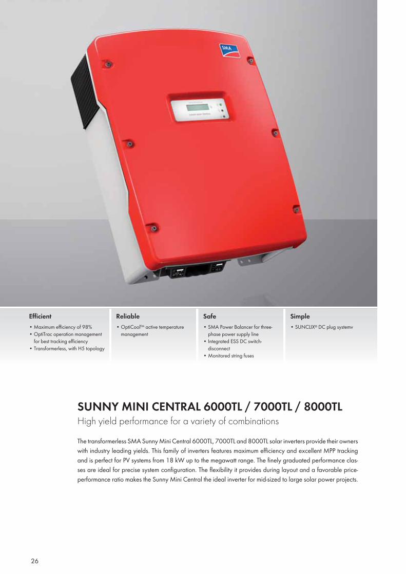
SUNNY MINI CENTRAL 6000TL / 7000TL / 8000TL High yield performance for a variety of combinationsThe transformerless SMA Sunny Mini Central 6000TL, 7000TL and 8000TL solar inverters provide their owners with industry leading yields. This family of inverters features maximum efficiency and excellent MPP tracking and is perfect for PV systems from 18 kW up to the megawatt range. The finely graduated performance clas-ses are ideal for precise system configuration. The flexibility it provides during layout and a favorable price-performance ratio makes the Sunny Mini Central the ideal inverter for mid-sized to large solar power projects.
Efficient• Maximum efficiency of 98%• OptiTrac operation management
for best tracking efficiency• Transformerless, with H5 topology
Reliable• OptiCool™ active temperature
management
Safe• SMA Power Balancer for three-
phase power supply line• Integrated ESS DC switch-
disconnect• Monitored string fuses
Simple• SUNCLIX® DC plug systemv
27
Inverters without Transformers
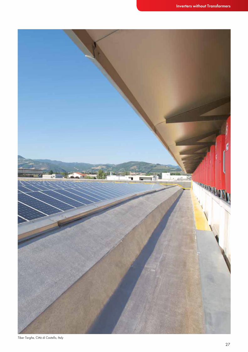
Tiber Targhe, Città di Castello, Italy
28
SUNNY MINI CENTRAL 6000TL / 7000TL / 8000TL
Input (DC)Max. DC power (@ cos ϕ=1)Max. input voltageMPP voltage range / rated input voltageMin. input voltage / initial input voltageMax. input currentMax. input current per stringNumber of independent MPP inputs / strings per MPP inputOutput (AC)Rated output power (@230 V, 50 Hz)Max. apparent AC powerNominal AC voltage / rangeAC power frequency / rangeRated power frequency / rated power voltageMax. output currentPower factor at rated output powerAdjustable displacement factorFeed-in phases / connection phasesPower balancingEffi ciencyMax. effi ciency / European effi ciencyProtectionReverse current protection / input-side disconnection deviceGround fault monitoring / grid monitoringDC reverse-polarity protection / AC short-circuit current capability / galvanically isolatedAll-pole sensitive residual current monitoring unitProtection class (according to IEC 62103) / overvoltage category (according to IEC 60664-1)General DataDimensions (W / H / D)
WeightOperating temperature rangeNoise emission (typical)Self-consumption (night)TopologyCooling conceptDegree of protection (according to IEC 60529)Degree of protection of connection area (according to IEC 60529)Climatic category (according to IEC 60721-3-4)Maximum permissible value for relative humidity (non-condensing)FeaturesDC terminalAC terminalDisplayInterface: RS485 / BluetoothWarranty: 5 / 10 / 15 / 20 / 25 yearsCertifi cates and approvals (more available on request)
Type designation
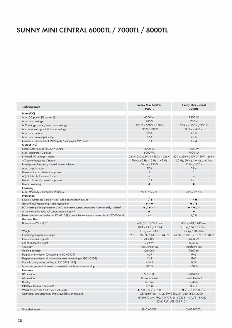
Technical Data Sunny Mini Central6000TL
Sunny Mini Central7000TL
7200 W700 V
333 V – 500 V / 350 V330 V / 400 V
22 A22 A1 / 4
7000 W7000 VA
220 V, 230 V, 240 V / 180 V – 265 V50 Hz, 60 Hz / -6 Hz … +5 Hz
50 Hz / 230 V31 A
1—
1 / 1●
98 % / 97.7 %
— / ●● / ●
● / ● / —●
I / III
468 / 613 / 242 mm (18.4 / 24.1 / 9.5 in)
32 kg / 70.55 lb-25 °C … +60 °C / -13 °F … +140 °F
33 dB(A)0.25 W
TransformerlessOptiCool
IP65IP65
4K4H100 %
SUNCLIXScrew terminal
Text line○ / ○
● / ○ / ○ / ○ / ○
6200 W700 V
333 V – 500 V / 350 V330 V / 400 V
19 A19 A1 / 4
6000 W6000 VA
220 V, 230 V, 240 V / 180 V – 265 V50 Hz, 60 Hz / -6 Hz … +5 Hz
50 Hz / 230 V27 A
1—
1 / 1●
98 % / 97.7 %
— / ●● / ●
● / ● / —●
I / III
468 / 613 / 242 mm (18.4 / 24.1 / 9.5 in)
31 kg / 68.34 lb-25 °C … +60 °C / -13 °F … +140 °F
31 dB(A)0.25 W
TransformerlessOptiCool
IP65IP65
4K4H100 %
SUNCLIXScrew terminal
Text line○ / ○
● / ○ / ○ / ○ / ○CE, VDE0126-1-1, DK 5940 ED2.2**, RD 1663/2000,
RD 661/2007, PPC, AS4777, EN 50438*, C10/11, PPDS, IEC 61727, UTE C15-712-1
SMC 6000TL SMC 7000TL

29
Inverters without Transformers
Accessories
Input (DC)Max. DC power (@ cos ϕ=1)Max. input voltageMPP voltage range / rated input voltageMin. input voltage / initial input voltageMax. input currentMax. input current per stringNumber of independent MPP inputs / strings per MPP inputOutput (AC)Rated output power (@230 V, 50 Hz)Max. apparent AC powerNominal AC voltage / rangeAC power frequency / rangeRated power frequency / rated power voltageMax. output currentPower factor at rated output powerAdjustable displacement factorFeed-in phases / connection phasesPower balancingEffi ciencyMax. effi ciency / European effi ciencyProtectionReverse current protection / input-side disconnection deviceGround fault monitoring / grid monitoringDC reverse-polarity protection / AC short-circuit current capability / galvanically isolatedAll-pole sensitive residual current monitoring unitProtection class (according to IEC 62103) / overvoltage category (according to IEC 60664-1)General DataDimensions (W / H / D)
WeightOperating temperature rangeNoise emission (typical)Self-consumption (night)TopologyCooling conceptDegree of protection (according to IEC 60529)Degree of protection of connection area (according to IEC 60529)Climatic category (according to IEC 60721-3-4)Maximum permissible value for relative humidity (non-condensing)FeaturesDC terminalAC terminalDisplayInterface: RS485 / BluetoothWarranty: 5 / 10 / 15 / 20 / 25 yearsCertifi cates and approvals (more available on request)
Type designation
Technical Data Sunny Mini Central8000TL
RS485 interface 485PB-SMC-NR
Bluetooth Piggy-BackBTPBINV-NR
SMA Power Balancer SetPlug-in systemPBL-SBUS-10-NR
● Standard features ○ Optional features — Not availableData at nominal conditions
* Does not apply to all national deviations of EN 50438** Only applies to IT option
8250 W700 V
333 V – 500 V / 350 V330 V / 400 V
25 A25 A1 / 4
8000 W8000 VA
220 V, 230 V, 240 V / 180 V – 265 V50 Hz, 60 Hz / -6 Hz … +5 Hz
50 Hz / 230 V35 A
1—
1 / 1●
98 % / 97.7 %
— / ●● / ●
Short-circuit diode / ● / ——
I / III
468 / 613 / 242 mm (18.4 / 24.1 / 9.5 in)
33 kg / 72.75 lb-25 °C … +60 °C / -13 °F … +140 °F
40 dB(A)0.25 W
TransformerlessOptiCool
IP65IP65
4K4H100 %
SUNCLIXScrew terminal
Text line○ / ○
● / ○ / ○ / ○ / ○CE, VDE0126-1-1, DK 5940 ED2.2**, RD 1663/2000,
RD 661/2007, PPC, AS4777, EN 50438*, C10/11, PPDS, IEC 61727, UTE C15-712-1
SMC 8000TL
30
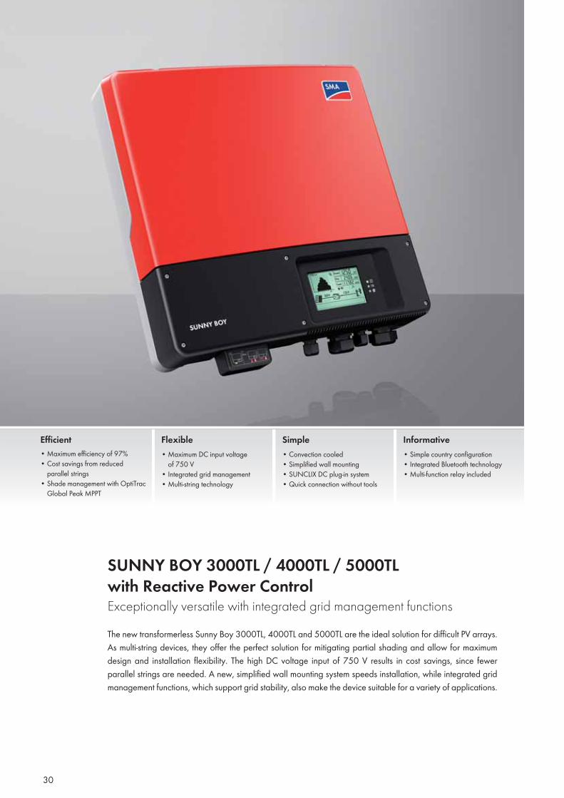
SUNNY BOY 3000TL / 4000TL / 5000TLwith Reactive Power ControlExceptionally versatile with integrated grid management functions The new transformerless Sunny Boy 3000TL, 4000TL and 5000TL are the ideal solution for difficult PV arrays. As multi-string devices, they offer the perfect solution for mitigating partial shading and allow for maximum design and installation flexibility. The high DC voltage input of 750 V results in cost savings, since fewer parallel strings are needed. A new, simplified wall mounting system speeds installation, while integrated grid management functions, which support grid stability, also make the device suitable for a variety of applications.
Efficient• Maximum efficiency of 97%• Cost savings from reduced parallel strings• Shade management with OptiTrac Global Peak MPPT
Flexible• Maximum DC input voltage of 750 V• Integrated grid management • Multi-string technology
Simple• Convection cooled• Simplified wall mounting• SUNCLIX DC plug-in system• Quick connection without tools
Informative• Simple country configuration• Integrated Bluetooth technology • Multi-function relay included
31
Inverters without Transformers
Niestetal, Germany
32
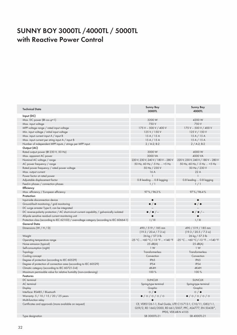
SUNNY BOY 3000TL /4000TL / 5000TL with Reactive Power Control
Input (DC)Max. DC power (@ cos ϕ=1)Max. input voltageMPP voltage range / rated input voltageMin. input voltage / initial input voltageMax. input current input A / input BMax. input current per string input A / input BNumber of independent MPP inputs / strings per MPP inputOutput (AC)Rated output power (@ 230 V, 50 Hz)Max. apparent AC powerNominal AC voltage / rangeAC power frequency / rangeRated power frequency / rated power voltageMax. output currentPower factor at rated powerAdjustable displacement factorFeed-in phases / connection phasesEffi ciencyMax. effi ciency / European effi ciencyProtectionInput-side disconnection deviceGround-fault monitoring / grid monitoringDC surge arrester Type II, can be integratedDC reverse-polarity protection / AC short-circuit current capability / galvanically isolatedAll-pole sensitive residual current monitoring unitProtection class (according to IEC 62103) / overvoltage category (according to IEC 60664-1)General DataDimensions (W / H / D)
WeightOperating temperature rangeNoise emission (typical)Self-consumption (night)TopologyCooling conceptDegree of protection (according to IEC 60529)Degree of protection of connection area (according to IEC 60529)Climatic category (according to IEC 60721-3-4)Maximum permissible value for relative humidity (non-condensing)FeaturesDC terminalAC terminalDisplayInterface: RS485 / BluetoothWarranty: 5 / 10 / 15 / 20 / 25 yearsMulti-function relayCertifi cates and approvals (more available on request)
Type designation
Technical Data Sunny Boy3000TL
Sunny Boy4000TL
3200 W750 V
175 V – 500 V / 400 V125 V / 150 V15 A / 15 A15 A / 15 A2 / A:2; B:2
3000 W3000 VA
220 V, 230 V, 240 V / 180 V – 280 V50 Hz, 60 Hz / -5 Hz … +5 Hz
50 Hz / 230 V16 A
10.8 leading … 0.8 lagging
1 / 1
97 % / 96.3 %
●● / ●
—● / ● / —
●I / III
490 / 519 / 185 mm (19.3 / 20.4 / 7.3 in)
26 kg / 57.3 lb-25 °C … +60 °C / -13 °F … +140 °F
25 dB(A)1 W
TransformerlessConvection
IP65IP54
4K4H100 %
SUNCLIXSpring-type terminal
Graphic○ / ●
● / ○ / ○ / ○ / ○●
CE, VDE0126-1-1, Enel Guida, UTE C15-712-1, C10/11, G83/1-1, G59/2, RD 1663/2000, RD 661/2007, PPC, AS4777, EN 50438*,
PPDS, VDE-AR-N 4105SB 3000TL-21
4200 W750 V
175 V – 500 V / 400 V125 V / 150 V15 A / 15 A15 A / 15 A2 / A:2; B:2
4000 W4000 VA
220 V, 230 V, 240 V / 180 V – 280 V50 Hz, 60 Hz / -5 Hz … +5 Hz
50 Hz / 230 V22 A
10.8 leading … 0.8 lagging
1 / 1
97 % / 96.4 %
●● / ●
—● / ● / —
●I / III
490 / 519 / 185 mm (19.3 / 20.5 / 7.3 in)
26 kg / 57.3 lb-25 °C … +60 °C / -13 °F … +140 °F
25 dB(A)1 W
TransformerlessConvection
IP65IP54
4K4H100 %
SUNCLIXSpring-type terminal
Graphic○ / ●
● / ○ / ○ / ○ / ○●
SB 4000TL-21
33
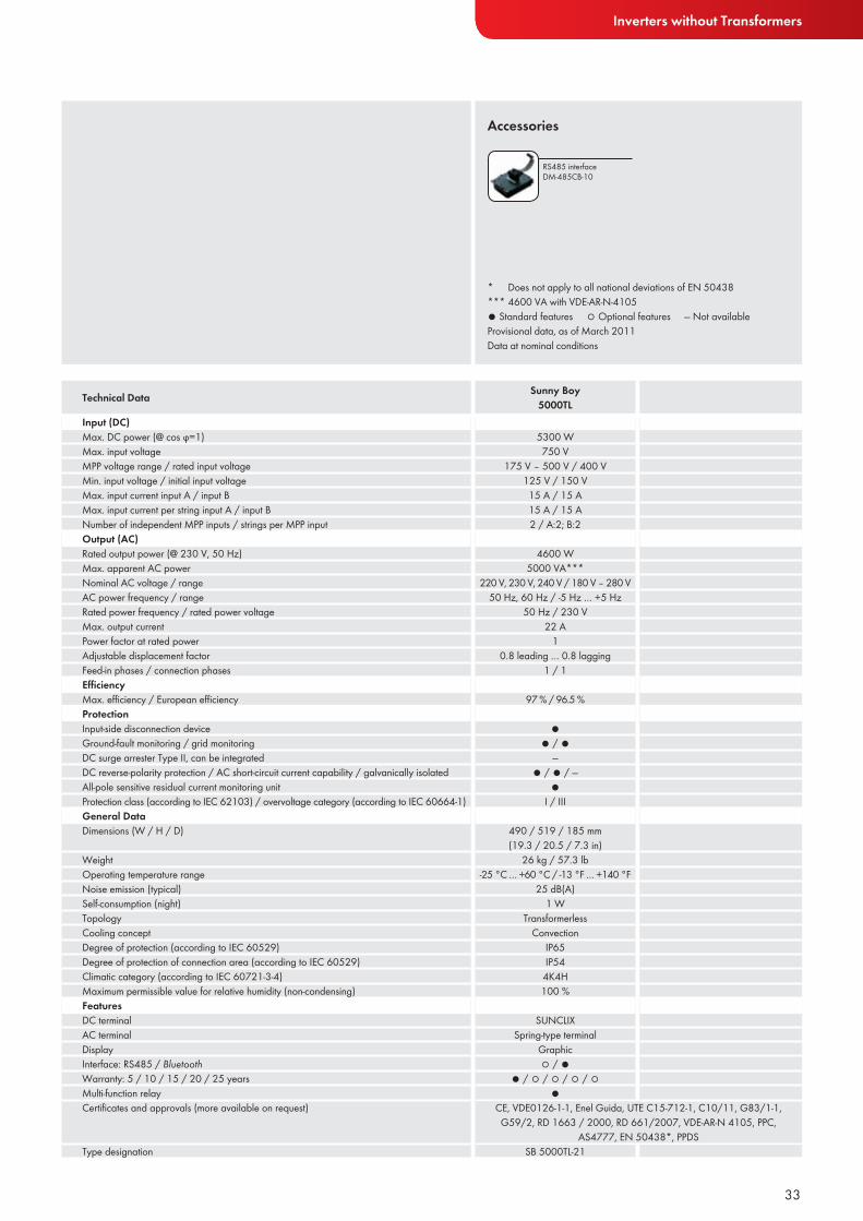
● Standard features ○ Optional features — Not availableProvisional data, as of March 2011Data at nominal conditions
Accessories
Input (DC)Max. DC power (@ cos ϕ=1)Max. input voltageMPP voltage range / rated input voltageMin. input voltage / initial input voltageMax. input current input A / input BMax. input current per string input A / input BNumber of independent MPP inputs / strings per MPP inputOutput (AC)Rated output power (@ 230 V, 50 Hz)Max. apparent AC powerNominal AC voltage / rangeAC power frequency / rangeRated power frequency / rated power voltageMax. output currentPower factor at rated powerAdjustable displacement factorFeed-in phases / connection phasesEffi ciencyMax. effi ciency / European effi ciencyProtectionInput-side disconnection deviceGround-fault monitoring / grid monitoringDC surge arrester Type II, can be integratedDC reverse-polarity protection / AC short-circuit current capability / galvanically isolatedAll-pole sensitive residual current monitoring unitProtection class (according to IEC 62103) / overvoltage category (according to IEC 60664-1)General DataDimensions (W / H / D)
WeightOperating temperature rangeNoise emission (typical)Self-consumption (night)TopologyCooling conceptDegree of protection (according to IEC 60529)Degree of protection of connection area (according to IEC 60529)Climatic category (according to IEC 60721-3-4)Maximum permissible value for relative humidity (non-condensing)FeaturesDC terminalAC terminalDisplayInterface: RS485 / BluetoothWarranty: 5 / 10 / 15 / 20 / 25 yearsMulti-function relayCertifi cates and approvals (more available on request)
Type designation
Technical Data Sunny Boy5000TL
RS485 interface DM-485CB-10
Inverters without Transformers
* Does not apply to all national deviations of EN 50438*** 4600 VA with VDE-AR-N-4105
5300 W750 V
175 V – 500 V / 400 V125 V / 150 V15 A / 15 A15 A / 15 A2 / A:2; B:2
4600 W5000 VA***
220 V, 230 V, 240 V / 180 V – 280 V50 Hz, 60 Hz / -5 Hz … +5 Hz
50 Hz / 230 V22 A
10.8 leading … 0.8 lagging
1 / 1
97 % / 96.5 %
●● / ●
—● / ● / —
●I / III
490 / 519 / 185 mm (19.3 / 20.5 / 7.3 in)
26 kg / 57.3 lb-25 °C … +60 °C / -13 °F … +140 °F
25 dB(A)1 W
TransformerlessConvection
IP65IP54
4K4H100 %
SUNCLIXSpring-type terminal
Graphic○ / ●
● / ○ / ○ / ○ / ○●
CE, VDE0126-1-1, Enel Guida, UTE C15-712-1, C10/11, G83/1-1, G59/2, RD 1663 / 2000, RD 661/2007, VDE-AR-N 4105, PPC,
AS4777, EN 50438*, PPDSSB 5000TL-21
34
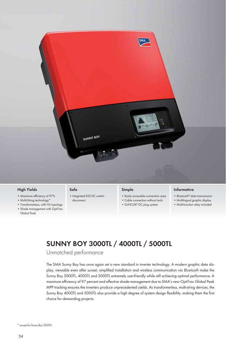
SUNNY BOY 3000TL / 4000TL / 5000TL Unmatched performance The SMA Sunny Boy has once again set a new standard in inverter technology. A modern graphic data dis-play, viewable even after sunset, simplified installation and wireless communication via Bluetooth make the Sunny Boy 3000TL, 4000TL and 5000TL extremely user-friendly while still achieving optimal performance. A maximum efficiency of 97 percent and effective shade management due to SMA’s new OptiTrac Global Peak MPP tracking ensures the inverters produce unprecedented yields. As transformerless, multi-string devices, the Sunny Boy 4000TL and 5000TL also provide a high degree of system design flexibility, making them the first choice for demanding projects.
High Yields• Maximum efficiency of 97%• Multi-String technology*• Transformerless, with H5 topology• Shade management with OptiTrac
Global Peak
Safe• Integrated ESS DC switch-
disconnect
Simple• Easily accessible connection area• Cable connection without tools• SUNCLIX® DC plug system
Informative• Bluetooth® data transmission• Multilingual graphic display• Multi-function relay included
* except for Sunny Boy 3000TL
35
Inverters without Transformers
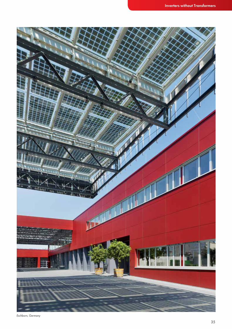
Eschborn, Germany
36
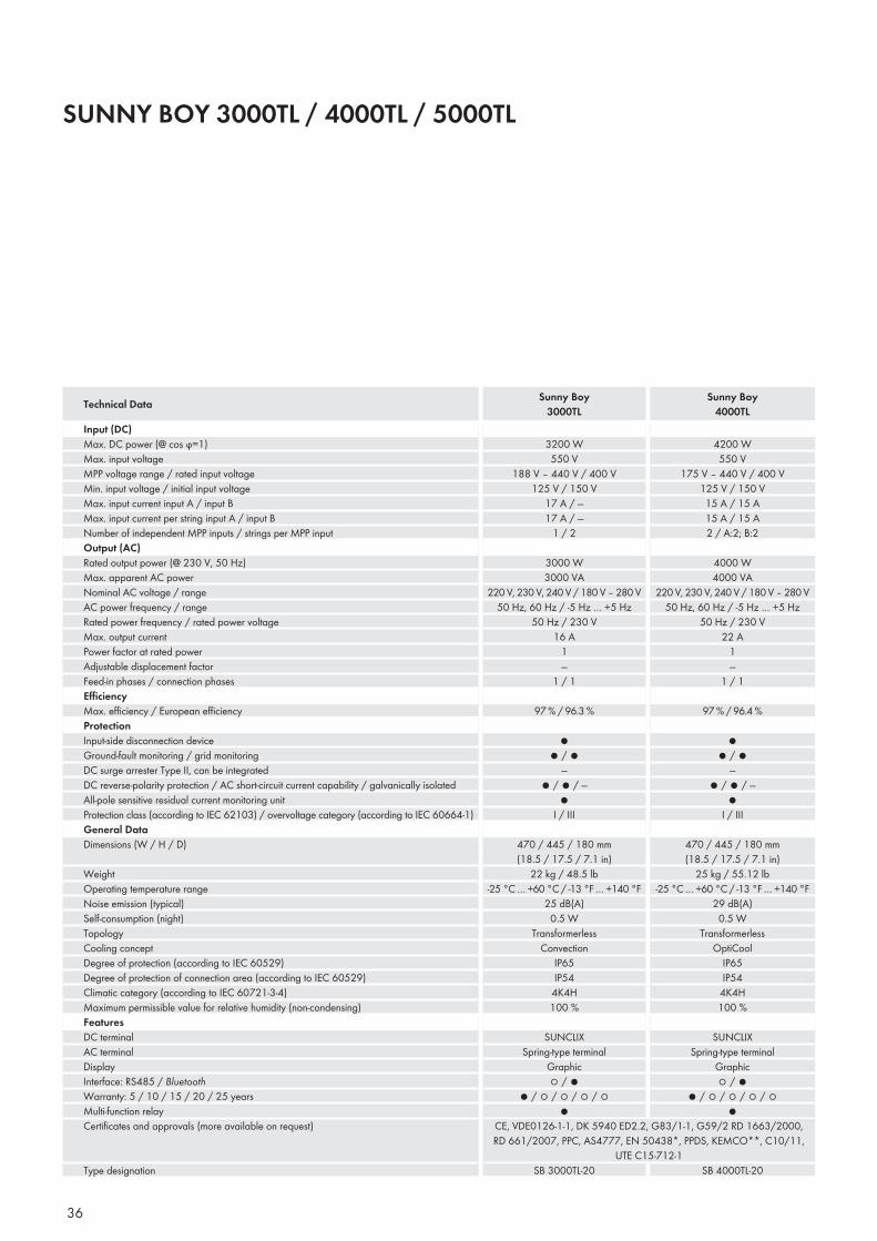
SUNNY BOY 3000TL / 4000TL / 5000TL
Input (DC)Max. DC power (@ cos ϕ=1)Max. input voltageMPP voltage range / rated input voltageMin. input voltage / initial input voltageMax. input current input A / input BMax. input current per string input A / input BNumber of independent MPP inputs / strings per MPP inputOutput (AC)Rated output power (@ 230 V, 50 Hz)Max. apparent AC powerNominal AC voltage / rangeAC power frequency / rangeRated power frequency / rated power voltageMax. output currentPower factor at rated powerAdjustable displacement factorFeed-in phases / connection phasesEffi ciencyMax. effi ciency / European effi ciencyProtectionInput-side disconnection deviceGround-fault monitoring / grid monitoringDC surge arrester Type II, can be integratedDC reverse-polarity protection / AC short-circuit current capability / galvanically isolatedAll-pole sensitive residual current monitoring unitProtection class (according to IEC 62103) / overvoltage category (according to IEC 60664-1)General DataDimensions (W / H / D)
WeightOperating temperature rangeNoise emission (typical)Self-consumption (night)TopologyCooling conceptDegree of protection (according to IEC 60529)Degree of protection of connection area (according to IEC 60529)Climatic category (according to IEC 60721-3-4)Maximum permissible value for relative humidity (non-condensing)FeaturesDC terminalAC terminalDisplayInterface: RS485 / BluetoothWarranty: 5 / 10 / 15 / 20 / 25 yearsMulti-function relayCertifi cates and approvals (more available on request)
Type designation
Technical Data Sunny Boy3000TL
Sunny Boy4000TL
4200 W550 V
175 V – 440 V / 400 V125 V / 150 V15 A / 15 A15 A / 15 A2 / A:2; B:2
4000 W4000 VA
220 V, 230 V, 240 V / 180 V – 280 V50 Hz, 60 Hz / -5 Hz … +5 Hz
50 Hz / 230 V22 A
1—
1 / 1
97 % / 96.4 %
●● / ●
—● / ● / —
●I / III
470 / 445 / 180 mm (18.5 / 17.5 / 7.1 in)
25 kg / 55.12 lb-25 °C … +60 °C / -13 °F … +140 °F
29 dB(A)0.5 W
TransformerlessOptiCool
IP65IP54
4K4H100 %
SUNCLIXSpring-type terminal
Graphic○ / ●
● / ○ / ○ / ○ / ○●
3200 W550 V
188 V – 440 V / 400 V125 V / 150 V
17 A / —17 A / —
1 / 2
3000 W3000 VA
220 V, 230 V, 240 V / 180 V – 280 V50 Hz, 60 Hz / -5 Hz … +5 Hz
50 Hz / 230 V16 A
1—
1 / 1
97 % / 96.3 %
●● / ●
—● / ● / —
●I / III
470 / 445 / 180 mm (18.5 / 17.5 / 7.1 in)
22 kg / 48.5 lb-25 °C … +60 °C / -13 °F … +140 °F
25 dB(A)0.5 W
TransformerlessConvection
IP65IP54
4K4H100 %
SUNCLIXSpring-type terminal
Graphic○ / ●
● / ○ / ○ / ○ / ○●
SB 4000TL-20
CE, VDE0126-1-1, DK 5940 ED2.2, G83/1-1, G59/2 RD 1663/2000, RD 661/2007, PPC, AS4777, EN 50438*, PPDS, KEMCO**, C10/11,
UTE C15-712-1SB 3000TL-20

37
Inverters without Transformers
● Standard features ○ Optional features — Not availableData at nominal conditions
Accessories
Input (DC)Max. DC power (@ cos ϕ=1)Max. input voltageMPP voltage range / rated input voltageMin. input voltage / initial input voltageMax. input current input A / input BMax. input current per string input A / input BNumber of independent MPP inputs / strings per MPP inputOutput (AC)Rated output power (@ 230 V, 50 Hz)Max. apparent AC powerNominal AC voltage / rangeAC power frequency / rangeRated power frequency / rated power voltageMax. output currentPower factor at rated powerAdjustable displacement factorFeed-in phases / connection phasesEffi ciencyMax. effi ciency / European effi ciencyProtectionInput-side disconnection deviceGround-fault monitoring / grid monitoringDC surge arrester Type II, can be integratedDC reverse-polarity protection / AC short-circuit current capability / galvanically isolatedAll-pole sensitive residual current monitoring unitProtection class (according to IEC 62103) / overvoltage category (according to IEC 60664-1)General DataDimensions (W / H / D)
WeightOperating temperature rangeNoise emission (typical)Self-consumption (night)TopologyCooling conceptDegree of protection (according to IEC 60529)Degree of protection of connection area (according to IEC 60529)Climatic category (according to IEC 60721-3-4)Maximum permissible value for relative humidity (non-condensing)FeaturesDC terminalAC terminalDisplayInterface: RS485 / BluetoothWarranty: 5 / 10 / 15 / 20 / 25 yearsMulti-function relayCertifi cates and approvals (more available on request)
Type designation
Technical Data Sunny Boy5000TL
RS485 interface DM-485CB-10
* Does not apply to all national deviations of EN 50438** Only for SB 3000TL-20
5300 W550 V
175 V – 440 V / 400 V125 V / 150 V15 A / 15 A15 A / 15 A2 / A:2; B:2
4600 W5000 VA
220 V, 230 V, 240 V / 180 V – 280 V50 Hz, 60 Hz / -5 Hz … +5 Hz
50 Hz / 230 V22 A
1—
1 / 1
97 % / 96.5 %
●● / ●
—● / ● / —
●I / III
470 / 445 / 180 mm (18.5 / 17.5 / 7.1 in)
25 kg / 55.12 lb-25 °C … +60 °C / -13 °F … +140 °F
29 dB(A)0.5 W
TransformerlessOptiCool
IP65IP54
4K4H100 %
SUNCLIXSpring-type terminal
Graphic○ / ●
● / ○ / ○ / ○ / ○●
CE, VDE0126-1-1, DK 5940 ED2.2, G83/1-1 G59/2, C10/11, UTE C15-712-1, RD 1663/2000, RD 661/2007, PPC, AS4777,
EN 50438*, PPDSSB 5000TL-20

38
SUNNY BOY 1600TL / 2100TLSmall inverters with big resultsCombining broad input voltage and current ranges, the transformerless Sunny Boy 2100TL HC can be con-nected to nearly all standard crystalline PV modules. The proven and reliable Sunny Boy 1600TL is the starter model among the transformerless inverters; nevertheless, its efficiency is top-notch. Its low weight and robust enclosure allow simple installation, both indoors and outdoors. The Sunny Boy 1600TL is the ideal inverter for small PV plants.
Efficient• 96% maximum efficiency• Transformerless
Safe• Integrated ESS DC switch-
disconnect
Reliable• Time proven technology• Maintenance free, thanks to
convection cooling
Simple• SUNCLIX® DC plug system

39
Inverters without Transformers
● Standard features ○ Optional features — Not availableFor SUNNY BOY 1600TL:Provisional data, as of March 2011Data at nominal conditions
Accessories
RS485 interface 485PB-NR
Bluetooth Piggy-BackBTPBINV-NR
Input (DC)Max. DC power (@ cos ϕ=1)Max. input voltageMPP voltage range / rated input voltageMin. input voltage / initial input voltageMax. input currentMax. input current per stringNumber of independent MPP inputs / strings per MPP inputOutput (AC)Rated output power (@ 230 V, 50 Hz)Max. apparent AC powerNominal AC voltage / rangeAC power frequency / rangeRated power frequency / rated power voltageMax. output currentPower factor at rated powerAdjustable displacement factorFeed-in phases / connection phasesEffi ciencyMax. effi ciency / European effi ciencyProtectionInput-side disconnection deviceGround-fault monitoring / grid monitoringDC surge arrester Type II, can be integratedDC reverse-polarity protection / AC short-circuit current capability / galvanically isolatedAll-pole sensitive residual current monitoring unitProtection class (according to IEC 62103) / overvoltage category (according to IEC 60664-1)General DataDimensions (W / H / D)
WeightOperating temperature rangeNoise emission (typical)Self-consumption (night)TopologyCooling conceptDegree of protection (according to IEC 60529)Degree of protection of connection area (according to IEC 60529)Climatic category (according to IEC 60721-3-4)Maximum permissible value for relative humidity (non-condensing)FeaturesDC terminalAC terminalDisplayInterface: RS485 / BluetoothWarranty: 5 / 10 / 15 / 20 / 25 yearsMulti-function relayCertifi cates and approvals (more available on request)
Type designation
Technical Data Sunny Boy 1600TL
Sunny Boy 2100TL
* Does not apply to all national appendixes to EN 50438
2200 W600 V
200 V – 480 V / 400 V125 V / 150 V
11 A11 A1 / 2
1950 W2100 VA
220 V, 230 V, 240 V / 180 V – 260 V50 Hz / -4.5 Hz … +2.5 Hz
50 Hz / 230 V11 A
1—
1 / 1
96 % / 95.2 %
○● / ●
—● / ● / —
●I / III
440 / 339 / 214 mm (17.3 / 13.4 / 8.4 in)
16 kg / 35.3 lb-25 °C … +60 °C / -13 °F … +140 °F
33 dB(A)0.1 W
TransformerlessConvection
IP65IP65
4K4H100 %
SUNCLIXConnectorText line○ / ○
● / ○ / ○ / ○ / ○—
1700 W600 V
155 V – 480 V / 400 V125 V / 150 V
11 A11 A1 / 1
1600 W1600 VA
220 V, 230 V, 240 V / 180 V – 260 V50 Hz / -4.5 Hz … +2.5 Hz
50 Hz / 230 V11 A
1—
1 / 1
96 % / 95 %
○● / ●
—● / ● / —
●I / III
440 / 339 / 214 mm (17.3 / 13.4 / 8.4 in)
16 kg / 35.3 lb-25 °C … +60 °C / -13 °F … +140 °F
33 dB(A)0.1 W
TransformerlessConvection
IP65IP65
4K4H100 %
SUNCLIXConnectorText line○ / ○
● / ○ / ○ / ○ / ○—
CE, VDE0126-1-1, AS4777, EN 50438*, PPDS, UTE C15-712-1, C10/11
SB 1600TL-10 SB 2100TL
40
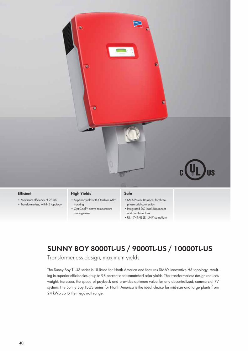
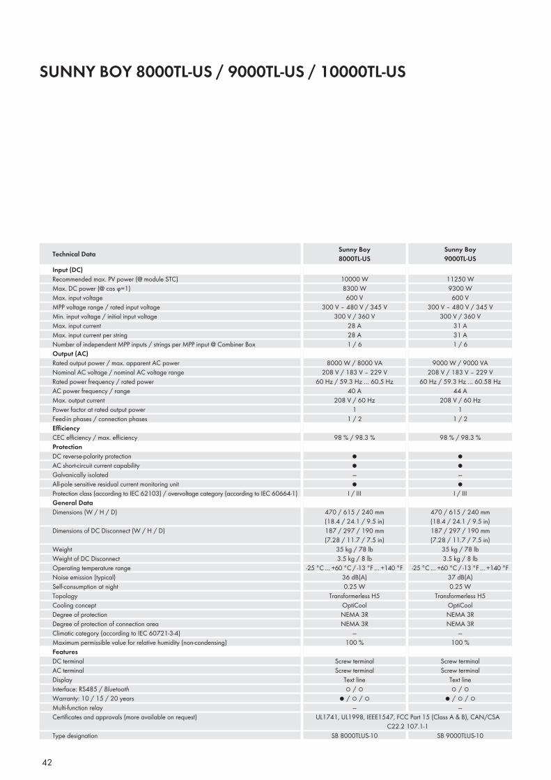
SUNNY BOY 8000TL-US / 9000TL-US / 10000TL-US Transformerless design, maximum yieldsThe Sunny Boy TL-US series is UL-listed for North America and features SMA’s innovative H5 topology, result-ing in superior efficiencies of up to 98 percent and unmatched solar yields. The transformerless design reduces weight, increases the speed of payback and provides optimum value for any decentralized, commercial PV system. The Sunny Boy TL-US series for North America is the ideal choice for mid-size and large plants from 24 kWp up to the megawatt range.
Efficient• Maximum efficiency of 98.3%• Transformerless, with H5 topology
High Yields• Superior yield with OptiTrac MPP
tracking• OptiCool™ active temperature
management
Safe• SMA Power Balancer for three-
phase grid connection• Integrated DC load disconnect
and combiner box• UL 1741/IEEE-1547 compliant
41
Inverters without Transformers
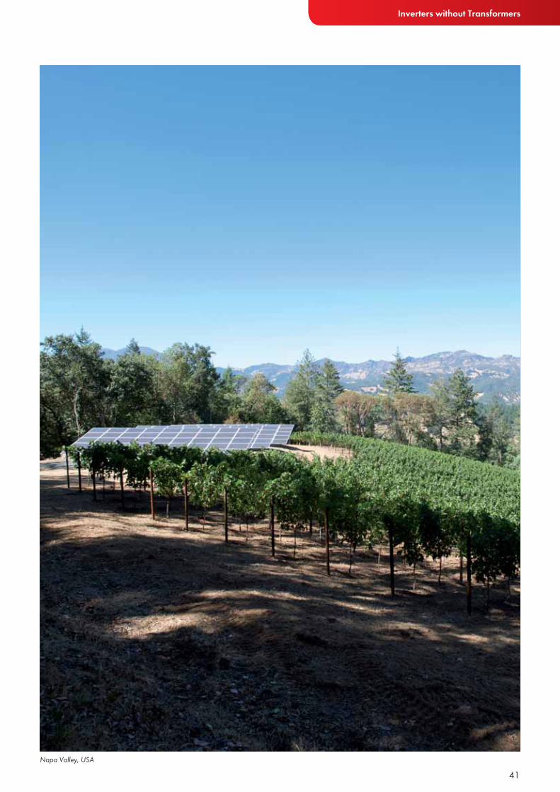
Napa Valley, USA
42
SUNNY BOY 8000TL-US / 9000TL-US / 10000TL-US
Input (DC)Recommended max. PV power (@ module STC)Max. DC power (@ cos ϕ=1)Max. input voltageMPP voltage range / rated input voltageMin. input voltage / initial input voltageMax. input currentMax. input current per stringNumber of independent MPP inputs / strings per MPP input @ Combiner BoxOutput (AC)Rated output power / max. apparent AC powerNominal AC voltage / nominal AC voltage rangeRated power frequency / rated powerAC power frequency / range Max. output currentPower factor at rated output powerFeed-in phases / connection phasesEffi ciencyCEC effi ciency / max. effi ciencyProtectionDC reverse-polarity protectionAC short-circuit current capabilityGalvanically isolatedAll-pole sensitive residual current monitoring unitProtection class (according to IEC 62103) / overvoltage category (according to IEC 60664-1)General DataDimensions (W / H / D)
Dimensions of DC Disconnect (W / H / D)
WeightWeight of DC DisconnectOperating temperature rangeNoise emission (typical)Self-consumption at nightTopologyCooling conceptDegree of protectionDegree of protection of connection areaClimatic category (according to IEC 60721-3-4)Maximum permissible value for relative humidity (non-condensing)FeaturesDC terminalAC terminalDisplayInterface: RS485 / BluetoothWarranty: 10 / 15 / 20 yearsMulti-function relayCertifi cates and approvals (more available on request)
Type designation
Technical Data Sunny Boy8000TL-US
Sunny Boy9000TL-US
11250 W9300 W600 V
300 V – 480 V / 345 V300 V / 360 V
31 A31 A1 / 6
9000 W / 9000 VA208 V / 183 V – 229 V
60 Hz / 59.3 Hz … 60.58 Hz44 A
208 V / 60 Hz1
1 / 2
98 % / 98.3 %
●●—●
I / III
470 / 615 / 240 mm (18.4 / 24.1 / 9.5 in)187 / 297 / 190 mm (7.28 / 11.7 / 7.5 in)
35 kg / 78 lb3.5 kg / 8 lb
-25 °C … +60 °C / -13 °F … +140 °F37 dB(A)0.25 W
Transformerless H5OptiCoolNEMA 3RNEMA 3R
—100 %
Screw terminalScrew terminal
Text line○ / ○
● / ○ / ○—
10000 W8300 W600 V
300 V – 480 V / 345 V300 V / 360 V
28 A28 A1 / 6
8000 W / 8000 VA208 V / 183 V – 229 V
60 Hz / 59.3 Hz … 60.5 Hz40 A
208 V / 60 Hz1
1 / 2
98 % / 98.3 %
●●—●
I / III
470 / 615 / 240 mm (18.4 / 24.1 / 9.5 in)187 / 297 / 190 mm (7.28 / 11.7 / 7.5 in)
35 kg / 78 lb3.5 kg / 8 lb
-25 °C … +60 °C / -13 °F … +140 °F36 dB(A)0.25 W
Transformerless H5OptiCoolNEMA 3RNEMA 3R
—100 %
Screw terminalScrew terminal
Text line○ / ○
● / ○ / ○—
UL1741, UL1998, IEEE1547, FCC Part 15 (Class A & B), CAN/CSA C22.2 107.1-1
SB 8000TLUS-10 SB 9000TLUS-10
43
Inverters without Transformers
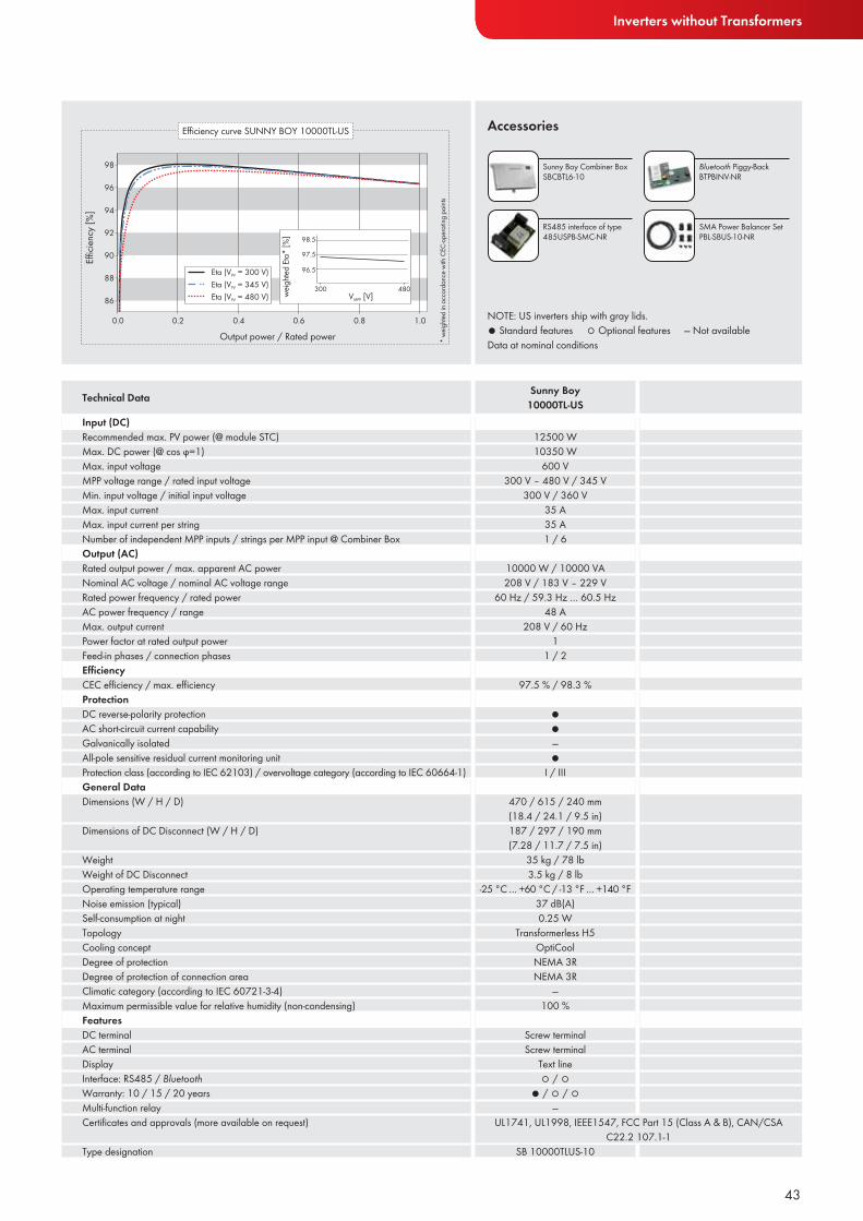
NOTE: US inverters ship with gray lids.● Standard features ○ Optional features — Not availableData at nominal conditions
Accessories
Input (DC)Recommended max. PV power (@ module STC)Max. DC power (@ cos ϕ=1)Max. input voltageMPP voltage range / rated input voltageMin. input voltage / initial input voltageMax. input currentMax. input current per stringNumber of independent MPP inputs / strings per MPP input @ Combiner BoxOutput (AC)Rated output power / max. apparent AC powerNominal AC voltage / nominal AC voltage rangeRated power frequency / rated powerAC power frequency / range Max. output currentPower factor at rated output powerFeed-in phases / connection phasesEffi ciencyCEC effi ciency / max. effi ciencyProtectionDC reverse-polarity protectionAC short-circuit current capabilityGalvanically isolatedAll-pole sensitive residual current monitoring unitProtection class (according to IEC 62103) / overvoltage category (according to IEC 60664-1)General DataDimensions (W / H / D)
Dimensions of DC Disconnect (W / H / D)
WeightWeight of DC DisconnectOperating temperature rangeNoise emission (typical)Self-consumption at nightTopologyCooling conceptDegree of protectionDegree of protection of connection areaClimatic category (according to IEC 60721-3-4)Maximum permissible value for relative humidity (non-condensing)FeaturesDC terminalAC terminalDisplayInterface: RS485 / BluetoothWarranty: 10 / 15 / 20 yearsMulti-function relayCertifi cates and approvals (more available on request)
Type designation
Technical Data Sunny Boy10000TL-US
Sunny Boy Combiner Box SBCBTL6-10
Bluetooth Piggy-BackBTPBINV-NR
RS485 interface of type 485USPB-SMC-NR
SMA Power Balancer SetPBL-SBUS-10-NR
12500 W10350 W
600 V300 V – 480 V / 345 V
300 V / 360 V35 A35 A1 / 6
10000 W / 10000 VA208 V / 183 V – 229 V
60 Hz / 59.3 Hz … 60.5 Hz48 A
208 V / 60 Hz1
1 / 2
97.5 % / 98.3 %
●●—●
I / III
470 / 615 / 240 mm (18.4 / 24.1 / 9.5 in)187 / 297 / 190 mm (7.28 / 11.7 / 7.5 in)
35 kg / 78 lb3.5 kg / 8 lb
-25 °C … +60 °C / -13 °F … +140 °F37 dB(A)0.25 W
Transformerless H5OptiCoolNEMA 3RNEMA 3R
—100 %
Screw terminalScrew terminal
Text line○ / ○
● / ○ / ○—
UL1741, UL1998, IEEE1547, FCC Part 15 (Class A & B), CAN/CSA C22.2 107.1-1
SB 10000TLUS-10
INVERTERS WITH TRANSFORMERS
44

45

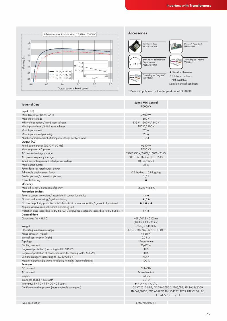
SUNNY MINI CENTRAL 7000HV The thin-film champion Thanks to a greater input voltage range in the Sunny Mini Central 7000HV, more modules can be connected in series than with common inverters. This reduces cabling costs on the DC side and simplifies installation. Due to its galvanic isolation, the Sunny Mini Central 7000HV can be used both with crystalline cells and thin-film modules. Its performance range allows for the installation of large PV arrays using smaller string inverters, resulting in more detailed system monitoring. Its new reactive power and grid management functions mean it is also suitable for international use.
Efficient• OptiCool™ active temperature
management• OptiTrac operation management
for best tracking efficiency
Safe• Galvanic isolation• Integrated ESS DC switch-
disconnect• SMA Power Balancer for three-
phase grid connection
Flexible• Integrated reactive power capabil-
ity and grid management functions• Input voltage range of up to 800 V• Suitable for array grounding*
Simple• SUNCLIX® DC plug system
46
Inverters with Transformers
Input (DC)Max. DC power (@ cos ϕ=1)Max. input voltageMPP voltage range / rated input voltageMin. input voltage / initial input voltageMax. input currentMax. input current per stringNumber of independent MPP inputs / strings per MPP inputOutput (AC)Rated output power (@230 V, 50 Hz)Max. apparent AC powerAC nominal voltage / rangeAC power frequency / rangeRated power frequency / rated power voltageMax. output currentPower factor at rated output powerAdjustable displacement factorFeed-in phases / connection phasesPower balancingEffi ciencyMax. effi ciency / European effi ciencyProtection devicesReverse current protection / input-side disconnection deviceGround fault monitoring / grid monitoringDC reverse-polarity protection / AC short-circuit current capability / galvanically isolatedAll-pole sensitive residual current monitoring unitProtection class (according to IEC 62103) / overvoltage category (according to IEC 60664-1)General dataDimensions (W / H / D)
WeightOperating temperature rangeNoise emission (typical)Internal consumption (night)TopologyCooling conceptDegree of protection (according to IEC 60529)Degree of protection of connection area (according to IEC 60529)Climatic category (according to IEC 60721-3-4)Maximum permissible value for relative humidity (non-condensing)FeaturesDC terminalAC terminalDisplayInterface: RS485 / BluetoothWarranty: 5 / 10 / 15 / 20 / 25 yearsCertifi cates and approvals (more available on request)
Type designation
Technical Data Sunny Mini Central 7000HV
Accessories
47
RS485 interface 485PB-SMC-NR
Bluetooth Piggy-BackBTPBINV-NR
SMA Power Balancer SetPlug-in systemPBL-SMC-10-NR
Grounding set ”negative”ESHV-N-NR
Grounding set ”Positive”ESHV-P-NR
● Standard features ○ Optional features— Not availableData at nominal conditions
* Does not apply to all national appendixes to EN 50438
7500 W800 V
335 V – 560 V / 340 V290 V / 400 V
23 A23 A1 / 4
6650 W7000 VA
220 V, 230 V, 240 V / 160 V – 265 V50 Hz, 60 Hz / -6 Hz … +5 Hz
50 Hz / 230 V31 A
10.8 leading … 0.8 lagging
1 / 1●
96.2 % / 95.5 %
— / ●● / ●
● / ● / ●—
I / III
468 / 613 / 242 mm (18.4 / 24.1 / 9.5 in)
65 kg / 143.3 lb-25 °C … +60 °C / -13 °F … +140 °F
41 dB(A)0.25 W
LF transformerOptiCool
IP65IP65
4K4H100 %
SUNCLIXScrew terminal
Text line○ / ○
● / ○ / ○ / ○ / ○CE, VDE0126-1-1, DK 5940 ED2.2, G83/1-1, RD 1663/2000,
RD 661/2007, PPC, AS4777, EN 50438*, PPDS, UTE C15-712-1, IEC 61727, C10 / 11
SMC 7000HV-11

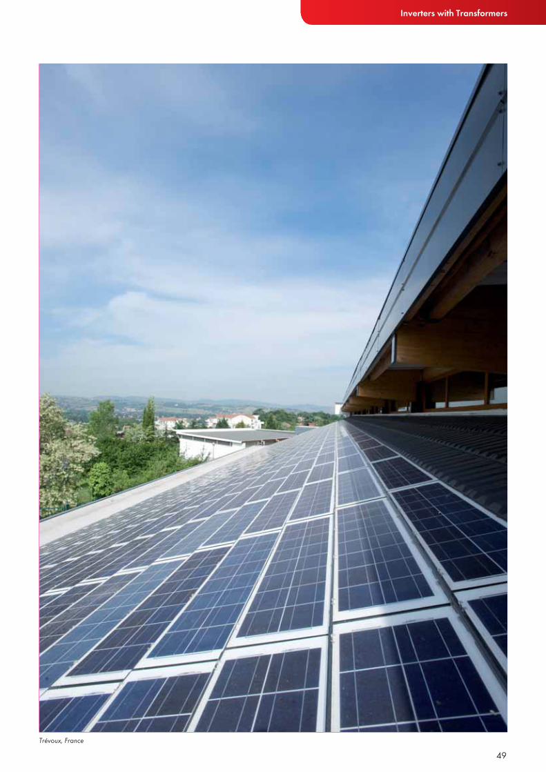
SUNNY MINI CENTRAL 4600A / 5000A / 6000A Proven technology for a multitude of applicationsThe Sunny Mini Central 4600A, 5000A and 6000A are designed for when galvanic isolation is required. This means they can be used around the world for many different types of projects, including those that use crystal-line cells or thin-film modules. Thanks to their graduated performance classes, these inverters offer the highest degree of system design flexibility. The Sunny Mini Centrals 5000A and 6000A are ideal for three-phase configurations, while the Sunny Mini Central 4600A is designed for single-phase systems.
Powerful• OptiCool™ active temperature
management• OptiTrac operation management
for best tracking efficiency
Safe• Galvanic isolation• Integrated ESS DC switch-
disconnect• SMA Power Balancer for three-
phase grid connection
Flexible• Suitable for array grounding*
Simple• SUNCLIX® DC plug system
48
Inverters with Transformers
49Trévoux, France
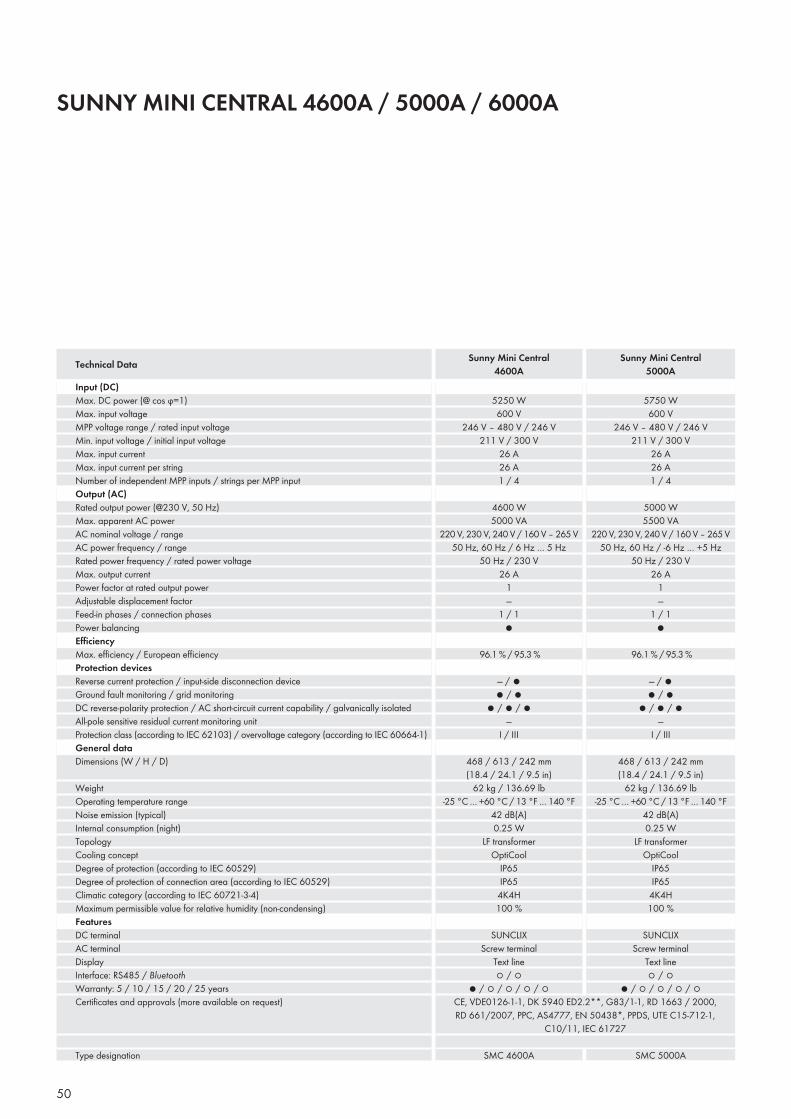
SUNNY MINI CENTRAL 4600A / 5000A / 6000A
Input (DC)Max. DC power (@ cos ϕ=1)Max. input voltageMPP voltage range / rated input voltageMin. input voltage / initial input voltageMax. input currentMax. input current per stringNumber of independent MPP inputs / strings per MPP inputOutput (AC)Rated output power (@230 V, 50 Hz)Max. apparent AC powerAC nominal voltage / rangeAC power frequency / rangeRated power frequency / rated power voltageMax. output currentPower factor at rated output powerAdjustable displacement factorFeed-in phases / connection phasesPower balancingEffi ciencyMax. effi ciency / European effi ciencyProtection devicesReverse current protection / input-side disconnection deviceGround fault monitoring / grid monitoringDC reverse-polarity protection / AC short-circuit current capability / galvanically isolatedAll-pole sensitive residual current monitoring unitProtection class (according to IEC 62103) / overvoltage category (according to IEC 60664-1)General dataDimensions (W / H / D)
WeightOperating temperature rangeNoise emission (typical)Internal consumption (night)TopologyCooling conceptDegree of protection (according to IEC 60529)Degree of protection of connection area (according to IEC 60529)Climatic category (according to IEC 60721-3-4)Maximum permissible value for relative humidity (non-condensing)FeaturesDC terminalAC terminalDisplayInterface: RS485 / BluetoothWarranty: 5 / 10 / 15 / 20 / 25 yearsCertifi cates and approvals (more available on request)
Type designation
Technical Data Sunny Mini Central4600A
Sunny Mini Central5000A
50
5750 W600 V
246 V – 480 V / 246 V211 V / 300 V
26 A26 A1 / 4
5000 W5500 VA
220 V, 230 V, 240 V / 160 V – 265 V50 Hz, 60 Hz / -6 Hz … +5 Hz
50 Hz / 230 V26 A
1—
1 / 1●
96.1 % / 95.3 %
— / ●● / ●
● / ● / ●—
I / III
468 / 613 / 242 mm (18.4 / 24.1 / 9.5 in)
62 kg / 136.69 lb-25 °C … +60 °C / 13 °F … 140 °F
42 dB(A)0.25 W
LF transformerOptiCool
IP65IP65
4K4H100 %
SUNCLIXScrew terminal
Text line○ / ○
● / ○ / ○ / ○ / ○
5250 W600 V
246 V – 480 V / 246 V211 V / 300 V
26 A26 A1 / 4
4600 W5000 VA
220 V, 230 V, 240 V / 160 V – 265 V50 Hz, 60 Hz / 6 Hz … 5 Hz
50 Hz / 230 V26 A
1—
1 / 1●
96.1 % / 95.3 %
— / ●● / ●
● / ● / ●—
I / III
468 / 613 / 242 mm (18.4 / 24.1 / 9.5 in)
62 kg / 136.69 lb-25 °C … +60 °C / 13 °F … 140 °F
42 dB(A)0.25 W
LF transformerOptiCool
IP65IP65
4K4H100 %
SUNCLIXScrew terminal
Text line○ / ○
● / ○ / ○ / ○ / ○CE, VDE0126-1-1, DK 5940 ED2.2**, G83/1-1, RD 1663 / 2000, RD 661/2007, PPC, AS4777, EN 50438*, PPDS, UTE C15-712-1,
C10/11, IEC 61727
SMC 4600A SMC 5000A
Inverters with Transformers
Accessories
Input (DC)Max. DC power (@ cos ϕ=1)Max. input voltageMPP voltage range / rated input voltageMin. input voltage / initial input voltageMax. input currentMax. input current per stringNumber of independent MPP inputs / strings per MPP inputOutput (AC)Rated output power (@230 V, 50 Hz)Max. apparent AC powerAC nominal voltage / rangeAC power frequency / rangeRated power frequency / rated power voltageMax. output currentPower factor at rated output powerAdjustable displacement factorFeed-in phases / connection phasesPower balancingEffi ciencyMax. effi ciency / European effi ciencyProtection devicesReverse current protection / input-side disconnection deviceGround fault monitoring / grid monitoringDC reverse-polarity protection / AC short-circuit current capability / galvanically isolatedAll-pole sensitive residual current monitoring unitProtection class (according to IEC 62103) / overvoltage category (according to IEC 60664-1)General dataDimensions (W / H / D)
WeightOperating temperature rangeNoise emission (typical)Internal consumption (night)TopologyCooling conceptDegree of protection (according to IEC 60529)Degree of protection of connection area (according to IEC 60529)Climatic category (according to IEC 60721-3-4)Maximum permissible value for relative humidity (non-condensing)FeaturesDC terminalAC terminalDisplayInterface: RS485 / BluetoothWarranty: 5 / 10 / 15 / 20 / 25 yearsCertifi cates and approvals (more available on request)
Type designation
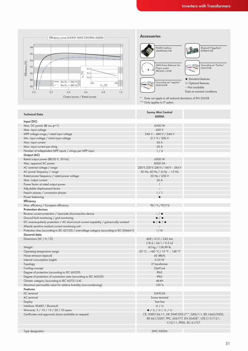
Technical Data Sunny Mini Central6000A
51
RS485 interface 485PB-SMC-NR
Bluetooth Piggy-BackBTPBINV-NR
SMA Power Balancer SetPlug-in systemPBL-SMC-10-NR
Grounding set ”negative”ESHV-N-NR
Grounding set ”Positive”ESHV-P-NR
● Standard features ○ Optional features— Not availableData at nominal conditions
* Does not apply to all national deviations of EN 50438** Only applies to IT option
6300 W600 V
246 V – 480 V / 246 V211 V / 300 V
26 A26 A1 / 4
6000 W6000 VA
220 V, 230 V, 240 V / 160 V – 265 V50 Hz, 60 Hz / -6 Hz … +5 Hz
50 Hz / 230 V26 A
1—
1 / 1●
96.1 % / 95.3 %
— / ●● / ●
● / ● / ●—
I / III
468 / 613 / 242 mm (18.4 / 24.1 / 9.5 in)
63 kg / 138.89 lb-25 °C … +60 °C / 13 °F … 140 °F
42 dB(A)0.25 W
LF transformerOptiCool
IP65IP65
4K4H100 %
SUNCLIXScrew terminal
Text line○ / ○
● / ○ / ○ / ○ / ○CE, VDE0126-1-1, DK 5940 ED2.2**, G83/1-1, RD 1663/2000,
RD 661/2007, PPC, AS4777, EN 50438*, UTE C15-712-1, C10/11, PPDS, IEC 61727
SMC 6000A
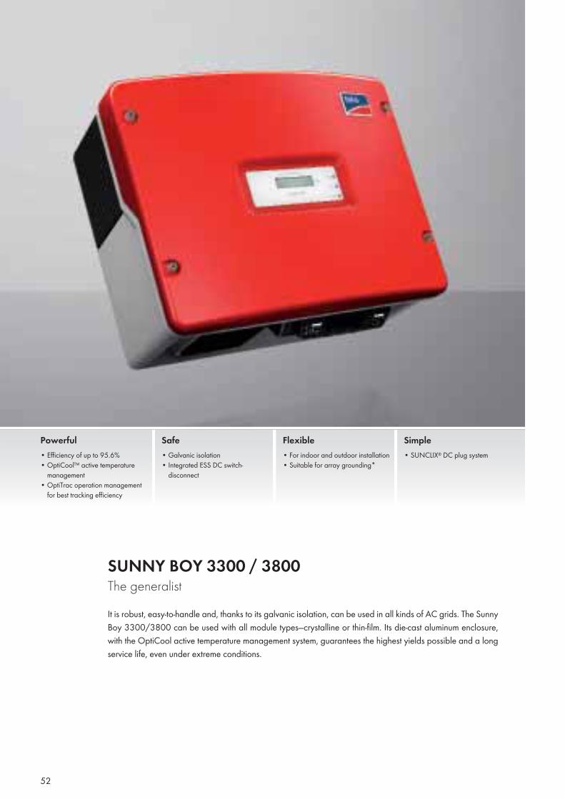
SUNNY BOY 3300 / 3800The generalistIt is robust, easy-to-handle and, thanks to its galvanic isolation, can be used in all kinds of AC grids. The Sunny Boy 3300/3800 can be used with all module types—crystalline or thin-film. Its die-cast aluminum enclosure, with the OptiCool active temperature management system, guarantees the highest yields possible and a long service life, even under extreme conditions.
Powerful• Efficiency of up to 95.6%• OptiCool™ active temperature
management• OptiTrac operation management
for best tracking efficiency
Safe• Galvanic isolation• Integrated ESS DC switch-
disconnect
Flexible• For indoor and outdoor installation• Suitable for array grounding*
Simple• SUNCLIX® DC plug system
52

Inverters with Transformers
Input (DC)Max. DC power (@ cos ϕ=1)Max. input voltageMPP voltage range / rated input voltageMin. input voltage / initial input voltageMax. input currentMax. input current per stringNumber of independent MPP inputs / strings per MPP inputOutput (AC)Rated output power (@ 230 V, 50 Hz)Max. apparent AC powerNominal AC voltage / rangeAC power frequency / rangeRated power frequency / rated power voltageMax. output currentPower factor at rated powerAdjustable displacement factorFeed-in phases / connection phasesEffi ciencyMax. effi ciency / European effi ciencyProtection devicesInput-side disconnection deviceGround-fault monitoring / grid monitoringDC surge arrester Type II, can be integratedDC reverse-polarity protection / AC short-circuit current capability / galvanically isolatedAll-pole sensitive residual current monitoring unitProtection class (according to IEC 62103) / overvoltage category (according to IEC 60664-1)General dataDimensions (W / H / D)
WeightOperating temperature rangeNoise emission (typical)Internal consumption (night)TopologyCooling conceptDegree of protection (according to IEC 60529)Degree of protection of connection area (according to IEC 60529)Climatic category (according to IEC 60721-3-4)Maximum permissible value for relative humidity (non-condensing)FeaturesDC terminalAC terminalDisplayInterface: RS485 / BluetoothWarranty: 5 / 10 / 15 / 20 / 25 yearsMulti-function relayCertifi cates and approvals (more available on request)
Type designation
Technical Data Sunny Boy 3300
Sunny Boy 3800
● Standard features ○ Optional features — Not availableData at nominal conditions
Accessories
53
RS485 interface 485PB-NR
Bluetooth Piggy-BackBTPBINV-NR
Grounding set ”Positive”ESHV-P-NR
Grounding set ”negative”ESHV-N-NR
4040 W500 V
200 V – 400 V / 200 V200 V / 250 V
20 A16 A1 / 3
3800 W3800 VA
220 V, 230 V, 240 V / 180 V – 265 V50 Hz, 60 Hz / -4.5 Hz … +4.5 Hz
50 Hz / 230 V18 A
1—
1 / 1
95.6 % / 94.7 %
●● / ●
—● / ● / ●
—I / III
450 / 352 / 236 mm (17.7 / 13.9 / 9.3 in)
38 kg / 83.6 lb-25 °C … +60 °C / -13 °F … +140 °F
42 dB(A)0.1 W
LF transformerOptiCool
IP65IP65
4K4H100 %
SUNCLIXConnectorText line○ / ○
● / ○ / ○ / ○ / ○—
3820 W500 V
200 V – 400 V / 200 V200 V / 250 V
20 A16 A1 / 3
3300 W3600 VA
220 V, 230 V, 240 V / 180 V – 265 V50 Hz, 60 Hz / -4.5 Hz … +4.5 Hz
50 Hz / 230 V18 A
1—
1 / 1
95.2 % / 94.4 %
●● / ●
—● / ● / ●
—I / III
450 / 352 / 236 mm (17.7 / 13.9 / 9.3 in)
38 kg / 83.6 lb-25 °C … +60 °C / -13 °F … +140 °F
40 dB(A)0.1 W
LF transformerOptiCool
IP65IP65
4K4H100 %
SUNCLIXConnectorText line○ / ○
● / ○ / ○ / ○ / ○—
CE, VDE0126-1-1, DK 5940 ED2.2**, G83/1-1, CER/06/190, RD 1663/2000, RD 661/2007, PPC, AS4777, EN 50438*, PPDS,
UTE C15-712-1, C10/11SB 3300 SB 3800
* Does not apply to all national deviations of EN 50438** Only applies to IT option
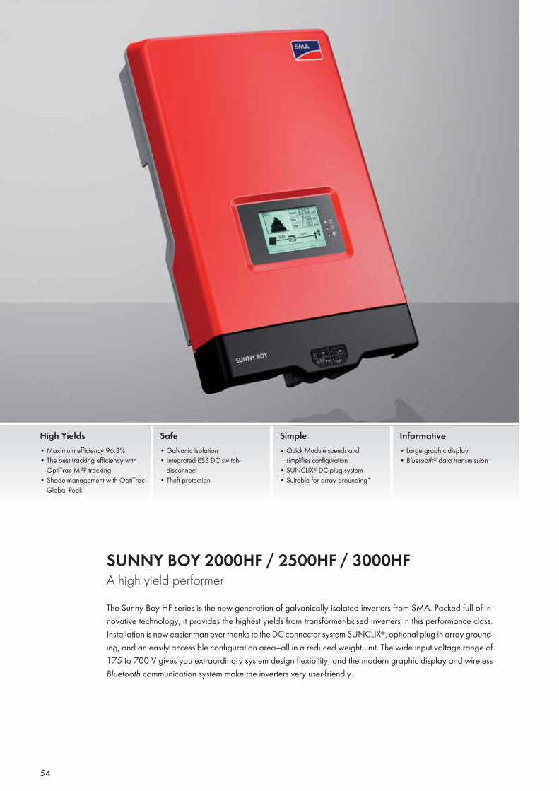
SUNNY BOY 2000HF / 2500HF / 3000HFA high yield performerThe Sunny Boy HF series is the new generation of galvanically isolated inverters from SMA. Packed full of in-novative technology, it provides the highest yields from transformer-based inverters in this performance class. Installation is now easier than ever thanks to the DC connector system SUNCLIX®, optional plug-in array ground-ing, and an easily accessible configuration area—all in a reduced weight unit. The wide input voltage range of 175 to 700 V gives you extraordinary system design flexibility, and the modern graphic display and wireless Bluetooth communication system make the inverters very user-friendly.
High Yields• Maximum efficiency 96.3%• The best tracking efficiency with
OptiTrac MPP tracking• Shade management with OptiTrac
Global Peak
Safe• Galvanic isolation• Integrated ESS DC switch-
disconnect• Theft protection
Simple• Quick Module speeds and
simplifies configuration • SUNCLIX® DC plug system• Suitable for array grounding*
Informative• Large graphic display• Bluetooth® data transmission
54
Inverters with Transformers
55Vieste, Italy
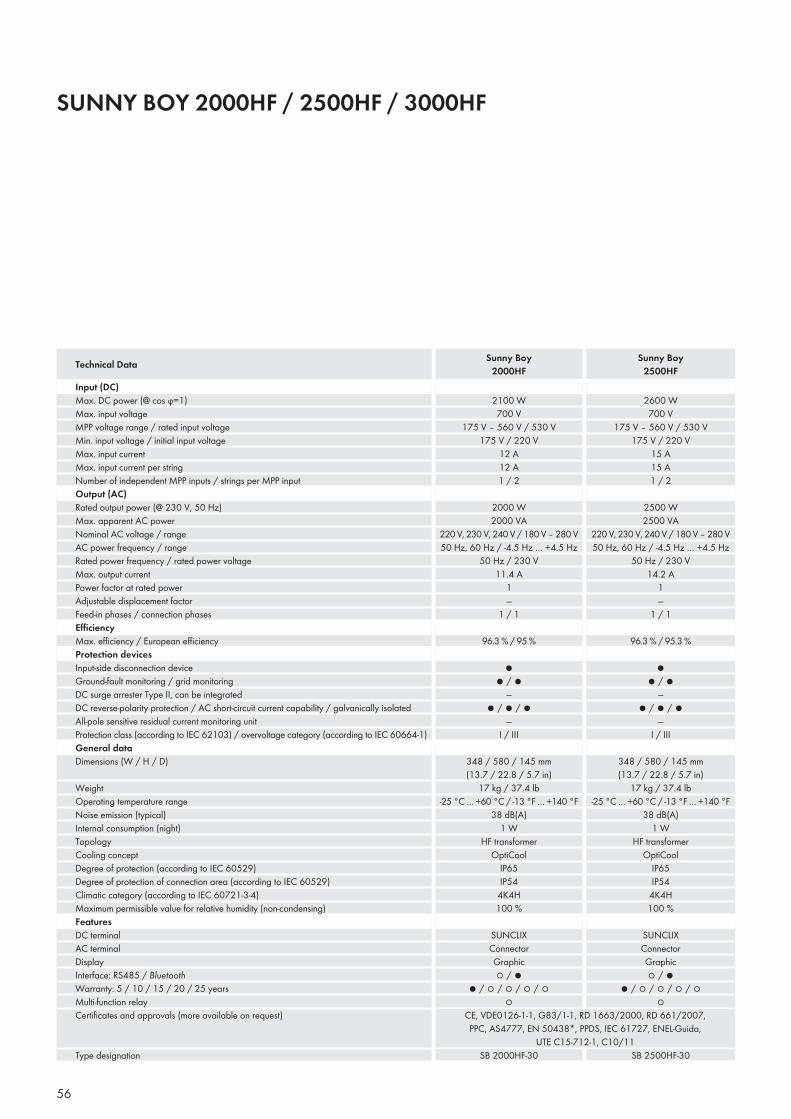
SUNNY BOY 2000HF / 2500HF / 3000HF
Input (DC)Max. DC power (@ cos ϕ=1)Max. input voltageMPP voltage range / rated input voltageMin. input voltage / initial input voltageMax. input currentMax. input current per stringNumber of independent MPP inputs / strings per MPP inputOutput (AC)Rated output power (@ 230 V, 50 Hz)Max. apparent AC powerNominal AC voltage / rangeAC power frequency / rangeRated power frequency / rated power voltageMax. output currentPower factor at rated powerAdjustable displacement factorFeed-in phases / connection phasesEffi ciencyMax. effi ciency / European effi ciencyProtection devicesInput-side disconnection deviceGround-fault monitoring / grid monitoringDC surge arrester Type II, can be integratedDC reverse-polarity protection / AC short-circuit current capability / galvanically isolatedAll-pole sensitive residual current monitoring unitProtection class (according to IEC 62103) / overvoltage category (according to IEC 60664-1)General dataDimensions (W / H / D)
WeightOperating temperature rangeNoise emission (typical)Internal consumption (night)TopologyCooling conceptDegree of protection (according to IEC 60529)Degree of protection of connection area (according to IEC 60529)Climatic category (according to IEC 60721-3-4)Maximum permissible value for relative humidity (non-condensing)FeaturesDC terminalAC terminalDisplayInterface: RS485 / BluetoothWarranty: 5 / 10 / 15 / 20 / 25 yearsMulti-function relayCertifi cates and approvals (more available on request)
Type designation
Technical Data Sunny Boy2000HF
Sunny Boy2500HF
56
2600 W700 V
175 V – 560 V / 530 V175 V / 220 V
15 A15 A1 / 2
2500 W2500 VA
220 V, 230 V, 240 V / 180 V – 280 V50 Hz, 60 Hz / -4.5 Hz … +4.5 Hz
50 Hz / 230 V14.2 A
1—
1 / 1
96.3 % / 95.3 %
●● / ●
—● / ● / ●
—I / III
348 / 580 / 145 mm (13.7 / 22.8 / 5.7 in)
17 kg / 37.4 lb-25 °C … +60 °C / -13 °F … +140 °F
38 dB(A)1 W
HF transformerOptiCool
IP65IP54
4K4H100 %
SUNCLIXConnectorGraphic○ / ●
● / ○ / ○ / ○ / ○○
2100 W700 V
175 V – 560 V / 530 V175 V / 220 V
12 A12 A1 / 2
2000 W2000 VA
220 V, 230 V, 240 V / 180 V – 280 V50 Hz, 60 Hz / -4.5 Hz … +4.5 Hz
50 Hz / 230 V11.4 A
1—
1 / 1
96.3 % / 95 %
●● / ●
—● / ● / ●
—I / III
348 / 580 / 145 mm (13.7 / 22.8 / 5.7 in)
17 kg / 37.4 lb-25 °C … +60 °C / -13 °F … +140 °F
38 dB(A)1 W
HF transformerOptiCool
IP65IP54
4K4H100 %
SUNCLIXConnectorGraphic○ / ●
● / ○ / ○ / ○ / ○○
CE, VDE0126-1-1, G83/1-1, RD 1663/2000, RD 661/2007, PPC, AS4777, EN 50438*, PPDS, IEC 61727, ENEL-Guida,
UTE C15-712-1, C10/11SB 2000HF-30 SB 2500HF-30
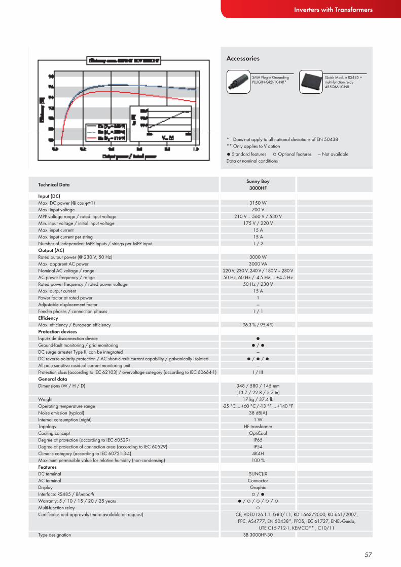
Inverters with Transformers
● Standard features ○ Optional features — Not availableData at nominal conditions
Accessories
Input (DC)Max. DC power (@ cos ϕ=1)Max. input voltageMPP voltage range / rated input voltageMin. input voltage / initial input voltageMax. input currentMax. input current per stringNumber of independent MPP inputs / strings per MPP inputOutput (AC)Rated output power (@ 230 V, 50 Hz)Max. apparent AC powerNominal AC voltage / rangeAC power frequency / rangeRated power frequency / rated power voltageMax. output currentPower factor at rated powerAdjustable displacement factorFeed-in phases / connection phasesEffi ciencyMax. effi ciency / European effi ciencyProtection devicesInput-side disconnection deviceGround-fault monitoring / grid monitoringDC surge arrester Type II, can be integratedDC reverse-polarity protection / AC short-circuit current capability / galvanically isolatedAll-pole sensitive residual current monitoring unitProtection class (according to IEC 62103) / overvoltage category (according to IEC 60664-1)General dataDimensions (W / H / D)
WeightOperating temperature rangeNoise emission (typical)Internal consumption (night)TopologyCooling conceptDegree of protection (according to IEC 60529)Degree of protection of connection area (according to IEC 60529)Climatic category (according to IEC 60721-3-4)Maximum permissible value for relative humidity (non-condensing)FeaturesDC terminalAC terminalDisplayInterface: RS485 / BluetoothWarranty: 5 / 10 / 15 / 20 / 25 yearsMulti-function relayCertifi cates and approvals (more available on request)
Type designation
Technical Data Sunny Boy3000HF
57
SMA Plug-in GroundingPLUGIN-GRD-10-NR*
Quick Module RS485 + multi-function relay 485QM-10-NR
* Does not apply to all national deviations of EN 50438** Only applies to V option
3150 W700 V
210 V – 560 V / 530 V175 V / 220 V
15 A15 A1 / 2
3000 W3000 VA
220 V, 230 V, 240 V / 180 V – 280 V50 Hz, 60 Hz / -4.5 Hz … +4.5 Hz
50 Hz / 230 V15 A
1—
1 / 1
96.3 % / 95.4 %
●● / ●
—● / ● / ●
—I / III
348 / 580 / 145 mm (13.7 / 22.8 / 5.7 in)
17 kg / 37.4 lb-25 °C … +60 °C / -13 °F … +140 °F
38 dB(A)1 W
HF transformerOptiCool
IP65IP54
4K4H100 %
SUNCLIXConnectorGraphic○ / ●
● / ○ / ○ / ○ / ○○
CE, VDE0126-1-1, G83/1-1, RD 1663/2000, RD 661/2007, PPC, AS4777, EN 50438*, PPDS, IEC 61727, ENEL-Guida,
UTE C15-712-1, KEMCO** , C10/11SB 3000HF-30
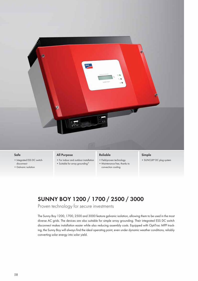
SUNNY BOY 1200 / 1700 / 2500 / 3000Proven technology for secure investmentsThe Sunny Boy 1200, 1700, 2500 and 3000 feature galvanic isolation, allowing them to be used in the most diverse AC grids. The devices are also suitable for simple array grounding. Their integrated ESS DC switch disconnect makes installation easier while also reducing assembly costs. Equipped with OptiTrac MPP track-ing, the Sunny Boy will always find the ideal operating point, even under dynamic weather conditions, reliably converting solar energy into solar yield.
Safe• Integrated ESS DC switch-
disconnect• Galvanic isolation
All Purpose• For indoor and outdoor installation• Suitable for array grounding*
Reliable• Field-proven technology• Maintenance free, thanks to
convection cooling
Simple• SUNCLIX® DC plug system
58
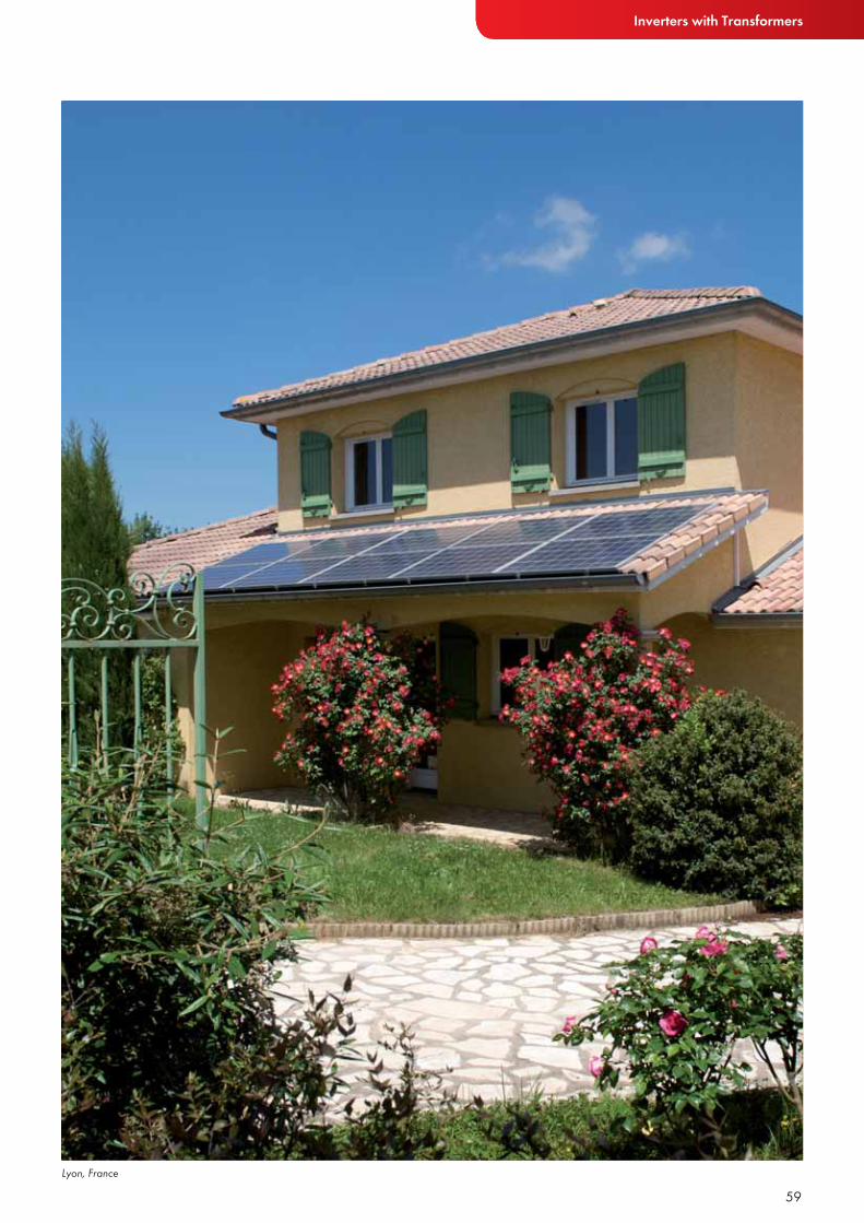
Inverters with Transformers
59Lyon, France
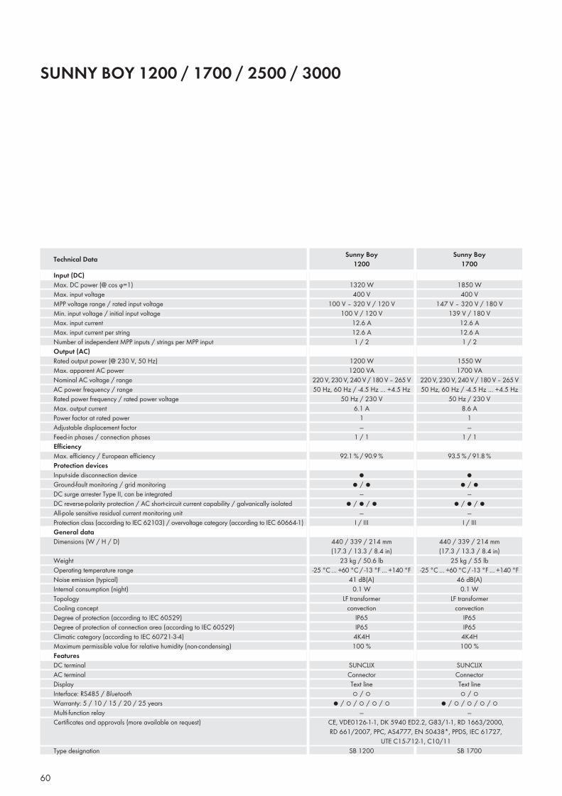
SUNNY BOY 1200 / 1700 / 2500 / 3000
Input (DC)Max. DC power (@ cos ϕ=1)Max. input voltageMPP voltage range / rated input voltageMin. input voltage / initial input voltageMax. input currentMax. input current per stringNumber of independent MPP inputs / strings per MPP inputOutput (AC)Rated output power (@ 230 V, 50 Hz)Max. apparent AC powerNominal AC voltage / rangeAC power frequency / rangeRated power frequency / rated power voltageMax. output currentPower factor at rated powerAdjustable displacement factorFeed-in phases / connection phasesEffi ciencyMax. effi ciency / European effi ciencyProtection devicesInput-side disconnection deviceGround-fault monitoring / grid monitoringDC surge arrester Type II, can be integratedDC reverse-polarity protection / AC short-circuit current capability / galvanically isolatedAll-pole sensitive residual current monitoring unitProtection class (according to IEC 62103) / overvoltage category (according to IEC 60664-1)General dataDimensions (W / H / D)
WeightOperating temperature rangeNoise emission (typical)Internal consumption (night)TopologyCooling conceptDegree of protection (according to IEC 60529)Degree of protection of connection area (according to IEC 60529)Climatic category (according to IEC 60721-3-4)Maximum permissible value for relative humidity (non-condensing)FeaturesDC terminalAC terminalDisplayInterface: RS485 / BluetoothWarranty: 5 / 10 / 15 / 20 / 25 yearsMulti-function relayCertifi cates and approvals (more available on request)
Type designation
Technical Data Sunny Boy1200
Sunny Boy1700
60
1850 W400 V
147 V – 320 V / 180 V139 V / 180 V
12.6 A12.6 A1 / 2
1550 W1700 VA
220 V, 230 V, 240 V / 180 V – 265 V50 Hz, 60 Hz / -4.5 Hz … +4.5 Hz
50 Hz / 230 V8.6 A
1—
1 / 1
93.5 % / 91.8 %
●● / ●
—● / ● / ●
—I / III
440 / 339 / 214 mm (17.3 / 13.3 / 8.4 in)
25 kg / 55 lb-25 °C … +60 °C / -13 °F … +140 °F
46 dB(A)0.1 W
LF transformerconvection
IP65IP65
4K4H100 %
SUNCLIXConnectorText line○ / ○
● / ○ / ○ / ○ / ○—
1320 W400 V
100 V – 320 V / 120 V100 V / 120 V
12.6 A12.6 A1 / 2
1200 W1200 VA
220 V, 230 V, 240 V / 180 V – 265 V50 Hz, 60 Hz / -4.5 Hz … +4.5 Hz
50 Hz / 230 V6.1 A
1—
1 / 1
92.1 % / 90.9 %
●● / ●
—● / ● / ●
—I / III
440 / 339 / 214 mm (17.3 / 13.3 / 8.4 in)
23 kg / 50.6 lb-25 °C … +60 °C / -13 °F … +140 °F
41 dB(A)0.1 W
LF transformerconvection
IP65IP65
4K4H100 %
SUNCLIXConnectorText line○ / ○
● / ○ / ○ / ○ / ○—
CE, VDE0126-1-1, DK 5940 ED2.2, G83/1-1, RD 1663/2000, RD 661/2007, PPC, AS4777, EN 50438*, PPDS, IEC 61727,
UTE C15-712-1, C10/11SB 1200 SB 1700
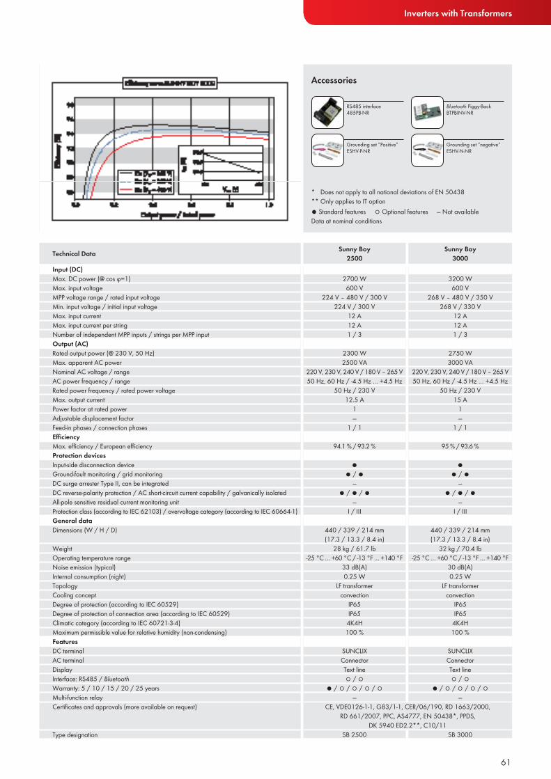
Inverters with Transformers
● Standard features ○ Optional features — Not availableData at nominal conditions
Accessories
Input (DC)Max. DC power (@ cos ϕ=1)Max. input voltageMPP voltage range / rated input voltageMin. input voltage / initial input voltageMax. input currentMax. input current per stringNumber of independent MPP inputs / strings per MPP inputOutput (AC)Rated output power (@ 230 V, 50 Hz)Max. apparent AC powerNominal AC voltage / rangeAC power frequency / rangeRated power frequency / rated power voltageMax. output currentPower factor at rated powerAdjustable displacement factorFeed-in phases / connection phasesEffi ciencyMax. effi ciency / European effi ciencyProtection devicesInput-side disconnection deviceGround-fault monitoring / grid monitoringDC surge arrester Type II, can be integratedDC reverse-polarity protection / AC short-circuit current capability / galvanically isolatedAll-pole sensitive residual current monitoring unitProtection class (according to IEC 62103) / overvoltage category (according to IEC 60664-1)General dataDimensions (W / H / D)
WeightOperating temperature rangeNoise emission (typical)Internal consumption (night)TopologyCooling conceptDegree of protection (according to IEC 60529)Degree of protection of connection area (according to IEC 60529)Climatic category (according to IEC 60721-3-4)Maximum permissible value for relative humidity (non-condensing)FeaturesDC terminalAC terminalDisplayInterface: RS485 / BluetoothWarranty: 5 / 10 / 15 / 20 / 25 yearsMulti-function relayCertifi cates and approvals (more available on request)
Type designation
Technical Data Sunny Boy2500
Sunny Boy3000
61
RS485 interface 485PB-NR
Bluetooth Piggy-BackBTPBINV-NR
Grounding set ”Positive”ESHV-P-NR
Grounding set ”negative”ESHV-N-NR
* Does not apply to all national deviations of EN 50438** Only applies to IT option
3200 W600 V
268 V – 480 V / 350 V268 V / 330 V
12 A12 A1 / 3
2750 W3000 VA
220 V, 230 V, 240 V / 180 V – 265 V50 Hz, 60 Hz / -4.5 Hz … +4.5 Hz
50 Hz / 230 V15 A
1—
1 / 1
95 % / 93.6 %
●● / ●
—● / ● / ●
—I / III
440 / 339 / 214 mm (17.3 / 13.3 / 8.4 in)
32 kg / 70.4 lb-25 °C … +60 °C / -13 °F … +140 °F
30 dB(A)0.25 W
LF transformerconvection
IP65IP65
4K4H100 %
SUNCLIXConnectorText line○ / ○
● / ○ / ○ / ○ / ○—
2700 W600 V
224 V – 480 V / 300 V224 V / 300 V
12 A12 A1 / 3
2300 W2500 VA
220 V, 230 V, 240 V / 180 V – 265 V50 Hz, 60 Hz / -4.5 Hz … +4.5 Hz
50 Hz / 230 V12.5 A
1—
1 / 1
94.1 % / 93.2 %
●● / ●
—● / ● / ●
—I / III
440 / 339 / 214 mm (17.3 / 13.3 / 8.4 in)
28 kg / 61.7 lb-25 °C … +60 °C / -13 °F … +140 °F
33 dB(A)0.25 W
LF transformerconvection
IP65IP65
4K4H100 %
SUNCLIXConnectorText line○ / ○
● / ○ / ○ / ○ / ○—
CE, VDE0126-1-1, G83/1-1, CER/06/190, RD 1663/2000, RD 661/2007, PPC, AS4777, EN 50438*, PPDS,
DK 5940 ED2.2**, C10/11SB 2500 SB 3000
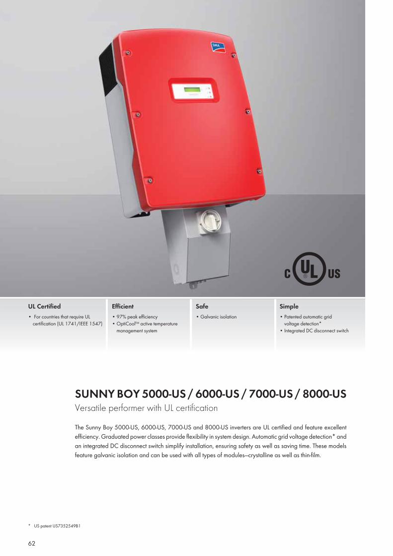
SUNNY BOY 5000-US / 6000-US / 7000-US / 8000-US Versatile performer with UL certificationThe Sunny Boy 5000-US, 6000-US, 7000-US and 8000-US inverters are UL certified and feature excellent efficiency. Graduated power classes provide flexibility in system design. Automatic grid voltage detection* and an integrated DC disconnect switch simplify installation, ensuring safety as well as saving time. These models feature galvanic isolation and can be used with all types of modules—crystalline as well as thin-film.
UL Certified• For countries that require UL
certification (UL 1741/IEEE 1547)
Efficient• 97% peak efficiency• OptiCool™ active temperature
management system
Safe• Galvanic isolation
Simple• Patented automatic grid
voltage detection*• Integrated DC disconnect switch
* US patent US7352549B1
62
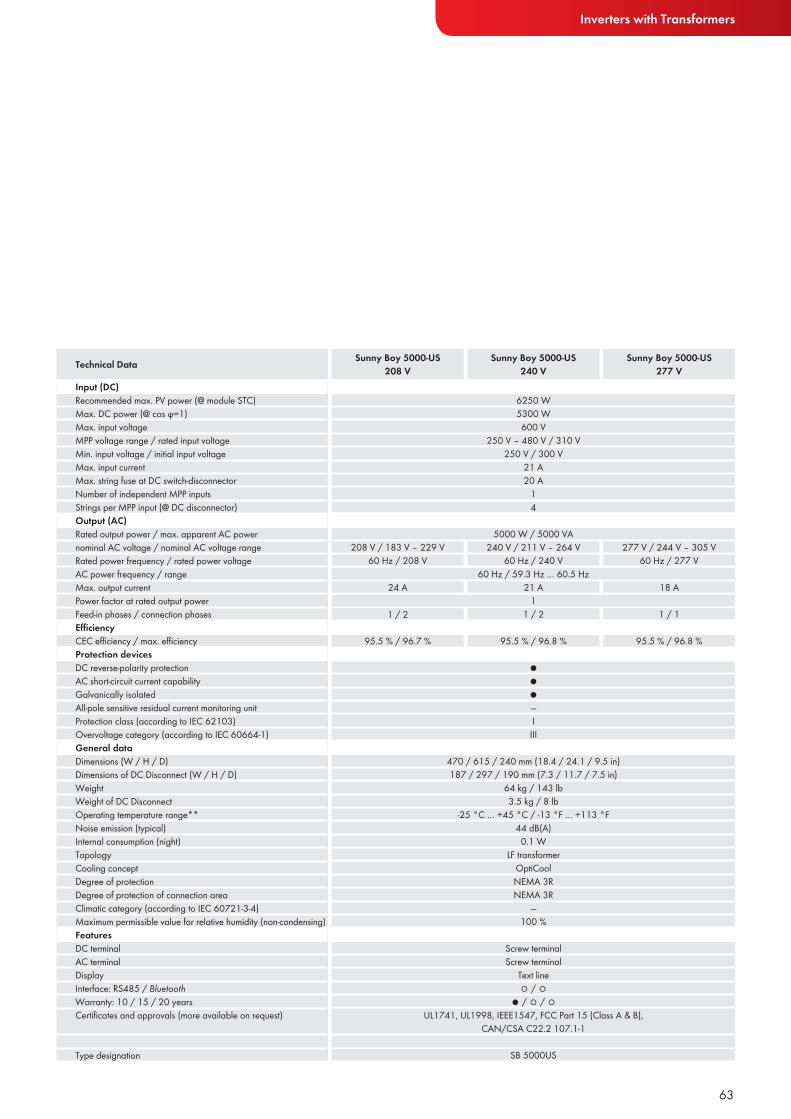
Inverters with Transformers
63
Sunny Boy 5000-US208 V
Sunny Boy 5000-US240 V
Sunny Boy 5000-US277 V
Input (DC)Recommended max. PV power (@ module STC)Max. DC power (@ cos ϕ=1)Max. input voltageMPP voltage range / rated input voltageMin. input voltage / initial input voltageMax. input currentMax. string fuse at DC switch-disconnectorNumber of independent MPP inputsStrings per MPP input (@ DC disconnector)Output (AC)Rated output power / max. apparent AC powernominal AC voltage / nominal AC voltage rangeRated power frequency / rated power voltageAC power frequency / range Max. output currentPower factor at rated output powerFeed-in phases / connection phasesEffi ciencyCEC effi ciency / max. effi ciencyProtection devicesDC reverse-polarity protectionAC short-circuit current capabilityGalvanically isolatedAll-pole sensitive residual current monitoring unitProtection class (according to IEC 62103)Overvoltage category (according to IEC 60664-1)General dataDimensions (W / H / D)Dimensions of DC Disconnect (W / H / D)WeightWeight of DC DisconnectOperating temperature range**Noise emission (typical)Internal consumption (night)TopologyCooling conceptDegree of protectionDegree of protection of connection areaClimatic category (according to IEC 60721-3-4)Maximum permissible value for relative humidity (non-condensing)FeaturesDC terminalAC terminalDisplayInterface: RS485 / BluetoothWarranty: 10 / 15 / 20 yearsCertifi cates and approvals (more available on request)
Type designation
Technical Data
6250 W5300 W600 V
250 V – 480 V / 310 V250 V / 300 V
21 A20 A
14
5000 W / 5000 VA
●●●—IIII
208 V / 183 V – 229 V60 Hz / 208 V
240 V / 211 V – 264 V60 Hz / 240 V
277 V / 244 V – 305 V60 Hz / 277 V
470 / 615 / 240 mm (18.4 / 24.1 / 9.5 in)187 / 297 / 190 mm (7.3 / 11.7 / 7.5 in)
64 kg / 143 lb3.5 kg / 8 lb
-25 °C … +45 °C / -13 °F … +113 °F44 dB(A)
0.1 WLF transformer
OptiCoolNEMA 3RNEMA 3R
—100 %
Screw terminalScrew terminal
Text line○ / ○
● / ○ / ○UL1741, UL1998, IEEE1547, FCC Part 15 (Class A & B),
CAN/CSA C22.2 107.1-1
SB 5000US
60 Hz / 59.3 Hz … 60.5 Hz
124 A
1 / 2
95.5 % / 96.7 %
21 A
1 / 2
95.5 % / 96.8 %
18 A
1 / 1
95.5 % / 96.8 %
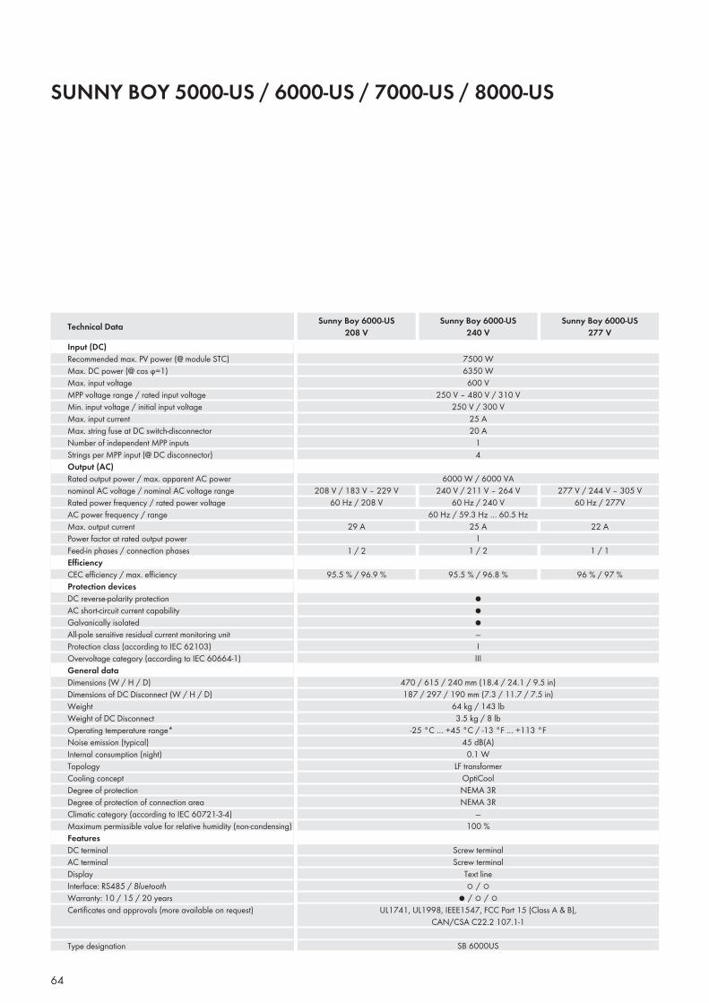
SUNNY BOY 5000-US / 6000-US / 7000-US / 8000-US
Input (DC)Recommended max. PV power (@ module STC)Max. DC power (@ cos ϕ=1)Max. input voltageMPP voltage range / rated input voltageMin. input voltage / initial input voltageMax. input currentMax. string fuse at DC switch-disconnectorNumber of independent MPP inputsStrings per MPP input (@ DC disconnector)Output (AC)Rated output power / max. apparent AC powernominal AC voltage / nominal AC voltage rangeRated power frequency / rated power voltageAC power frequency / range Max. output currentPower factor at rated output powerFeed-in phases / connection phasesEffi ciencyCEC effi ciency / max. effi ciencyProtection devicesDC reverse-polarity protectionAC short-circuit current capabilityGalvanically isolatedAll-pole sensitive residual current monitoring unitProtection class (according to IEC 62103)Overvoltage category (according to IEC 60664-1)General dataDimensions (W / H / D)Dimensions of DC Disconnect (W / H / D)WeightWeight of DC DisconnectOperating temperature range*Noise emission (typical)Internal consumption (night)TopologyCooling conceptDegree of protectionDegree of protection of connection areaClimatic category (according to IEC 60721-3-4)Maximum permissible value for relative humidity (non-condensing)FeaturesDC terminalAC terminalDisplayInterface: RS485 / BluetoothWarranty: 10 / 15 / 20 yearsCertifi cates and approvals (more available on request)
Type designation
Technical Data
64
Sunny Boy 6000-US208 V
Sunny Boy 6000-US240 V
Sunny Boy 6000-US277 V
7500 W6350 W600 V
250 V – 480 V / 310 V250 V / 300 V
25 A20 A
14
6000 W / 6000 VA
●●●—IIII
208 V / 183 V – 229 V60 Hz / 208 V
240 V / 211 V – 264 V60 Hz / 240 V
277 V / 244 V – 305 V60 Hz / 277V
470 / 615 / 240 mm (18.4 / 24.1 / 9.5 in)187 / 297 / 190 mm (7.3 / 11.7 / 7.5 in)
64 kg / 143 lb3.5 kg / 8 lb
-25 °C … +45 °C / -13 °F … +113 °F45 dB(A)
0.1 WLF transformer
OptiCoolNEMA 3RNEMA 3R
—100 %
Screw terminalScrew terminal
Text line ○ / ○
● / ○ / ○UL1741, UL1998, IEEE1547, FCC Part 15 (Class A & B),
CAN/CSA C22.2 107.1-1
SB 6000US
60 Hz / 59.3 Hz … 60.5 Hz
129 A
1 / 2
95.5 % / 96.9 %
25 A
1 / 2
95.5 % / 96.8 %
22 A
1 / 1
96 % / 97 %
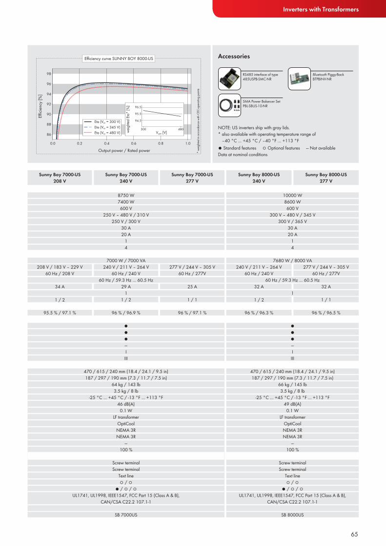
Inverters with Transformers
● Standard features ○ Optional features — Not availableData at nominal conditions
Accessories
65
RS485 interface of type 485USPB-SMC-NR
Bluetooth Piggy-BackBTPBINV-NR
Sunny Boy 7000-US208 V
Sunny Boy 7000-US240 V
Sunny Boy 7000-US277 V
Sunny Boy 8000-US240 V
Sunny Boy 8000-US277 V
NOTE: US inverters ship with gray lids.* also available with operating temperature range of
–40 °C … +45 °C / –40 °F … +113 °F
SMA Power Balancer SetPBL-SBUS-10-NR
8750 W7400 W600 V
250 V – 480 V / 310 V250 V / 300 V
30 A20 A
14
10000 W8600 W600 V
300 V – 480 V / 345 V300 V / 365 V
30 A20 A
14
7000 W / 7000 VA 7680 W / 8000 VA
●●●—IIII
●●●—IIII
208 V / 183 V – 229 V60 Hz / 208 V
240 V / 211 V – 264 V60 Hz / 240 V
277 V / 244 V – 305 V60 Hz / 277V
240 V / 211 V – 264 V60 Hz / 240 V
277 V / 244 V – 305 V60 Hz / 277V
470 / 615 / 240 mm (18.4 / 24.1 / 9.5 in)187 / 297 / 190 mm (7.3 / 11.7 / 7.5 in)
64 kg / 143 lb3.5 kg / 8 lb
-25 °C … +45 °C / -13 °F … +113 °F46 dB(A)
0.1 WLF transformer
OptiCoolNEMA 3RNEMA 3R
—100 %
Screw terminalScrew terminal
Text line ○ / ○
● / ○ / ○UL1741, UL1998, IEEE1547, FCC Part 15 (Class A & B),
CAN/CSA C22.2 107.1-1
470 / 615 / 240 mm (18.4 / 24.1 / 9.5 in)187 / 297 / 190 mm (7.3 / 11.7 / 7.5 in)
66 kg / 145 lb3.5 kg / 8 lb
-25 °C … +45 °C / -13 °F … +113 °F49 dB(A)
0.1 WLF transformer
OptiCoolNEMA 3RNEMA 3R
—100 %
Screw terminalScrew terminal
Text line○ / ○
● / ○ / ○UL1741, UL1998, IEEE1547, FCC Part 15 (Class A & B),
CAN/CSA C22.2 107.1-1
SB 7000US SB 8000US
60 Hz / 59.3 Hz … 60.5 Hz 60 Hz / 59.3 Hz … 60.5 Hz
1 134 A
1 / 2
95.5 % / 97.1 %
29 A
1 / 2
96 % / 96.9 %
25 A 32 A 32 A
1 / 1 1 / 2 1 / 1
96 % / 97.1 % 96 % / 96.3 % 96 % / 96.5 %
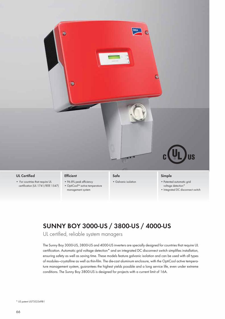
SUNNY BOY 3000-US / 3800-US / 4000-USUL certified, reliable system managersThe Sunny Boy 3000-US, 3800-US and 4000-US inverters are specially designed for countries that require UL certification. Automatic grid voltage detection* and an integrated DC disconnect switch simplifies installation, ensuring safety as well as saving time. These models feature galvanic isolation and can be used with all types of modules—crystalline as well as thin-film. The die-cast aluminum enclosure, with the OptiCool active tempera-ture management system, guarantees the highest yields possible and a long service life, even under extreme conditions. The Sunny Boy 3800-US is designed for projects with a current limit of 16A.
UL Certified• For countries that require UL
certification (UL 1741/IEEE 1547)
Efficient• 96.8% peak efficiency• OptiCool™ active temperature
management system
Safe• Galvanic isolation
Simple• Patented automatic grid
voltage detection*• Integrated DC disconnect switch
* US patent US7352549B1
66
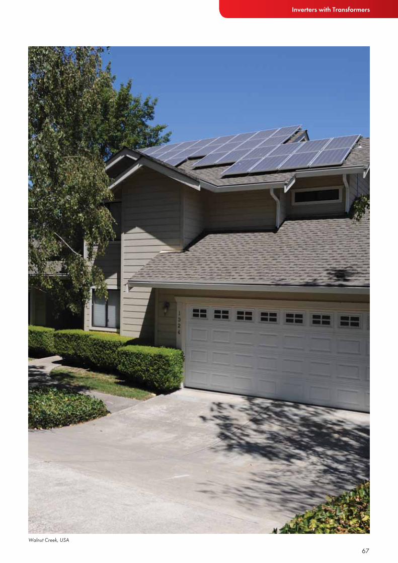
Inverters with Transformers
67Walnut Creek, USA
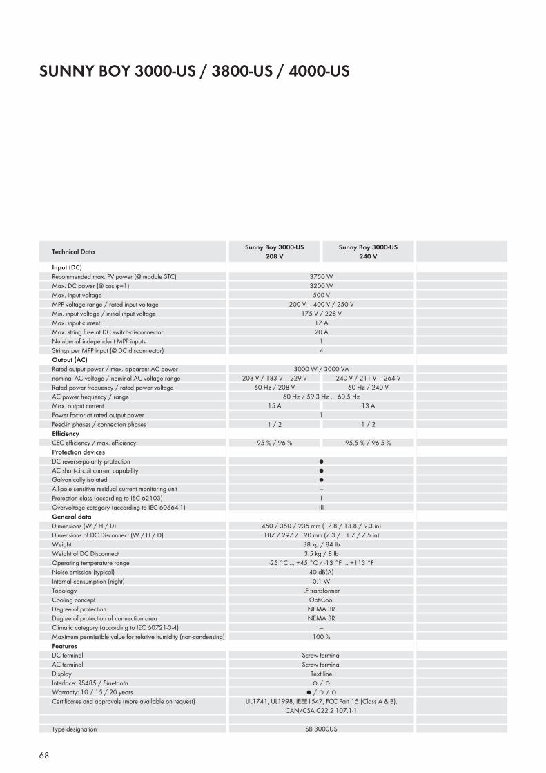
SUNNY BOY 3000-US / 3800-US / 4000-US
Input (DC)Recommended max. PV power (@ module STC)Max. DC power (@ cos ϕ=1)Max. input voltageMPP voltage range / rated input voltageMin. input voltage / initial input voltageMax. input currentMax. string fuse at DC switch-disconnectorNumber of independent MPP inputsStrings per MPP input (@ DC disconnector)Output (AC)Rated output power / max. apparent AC powernominal AC voltage / nominal AC voltage rangeRated power frequency / rated power voltageAC power frequency / range Max. output currentPower factor at rated output powerFeed-in phases / connection phasesEffi ciencyCEC effi ciency / max. effi ciencyProtection devicesDC reverse-polarity protectionAC short-circuit current capabilityGalvanically isolatedAll-pole sensitive residual current monitoring unitProtection class (according to IEC 62103)Overvoltage category (according to IEC 60664-1)General dataDimensions (W / H / D)Dimensions of DC Disconnect (W / H / D)WeightWeight of DC DisconnectOperating temperature rangeNoise emission (typical)Internal consumption (night)TopologyCooling conceptDegree of protectionDegree of protection of connection areaClimatic category (according to IEC 60721-3-4)Maximum permissible value for relative humidity (non-condensing)FeaturesDC terminalAC terminalDisplayInterface: RS485 / BluetoothWarranty: 10 / 15 / 20 yearsCertifi cates and approvals (more available on request)
Type designation
Technical Data Sunny Boy 3000-US208 V
Sunny Boy 3000-US240 V
68
3750 W3200 W500 V
200 V – 400 V / 250 V175 V / 228 V
17 A20 A
14
3000 W / 3000 VA
●●●—IIII
208 V / 183 V – 229 V60 Hz / 208 V
240 V / 211 V – 264 V60 Hz / 240 V
450 / 350 / 235 mm (17.8 / 13.8 / 9.3 in)187 / 297 / 190 mm (7.3 / 11.7 / 7.5 in)
38 kg / 84 lb3.5 kg / 8 lb
-25 °C … +45 °C / -13 °F … +113 °F40 dB(A)
0.1 WLF transformer
OptiCoolNEMA 3RNEMA 3R
—100 %
Screw terminalScrew terminal
Text line○ / ○
● / ○ / ○UL1741, UL1998, IEEE1547, FCC Part 15 (Class A & B),
CAN/CSA C22.2 107.1-1
SB 3000US
60 Hz / 59.3 Hz … 60.5 Hz
115 A
1 / 2
95 % / 96 %
13 A
1 / 2
95.5 % / 96.5 %
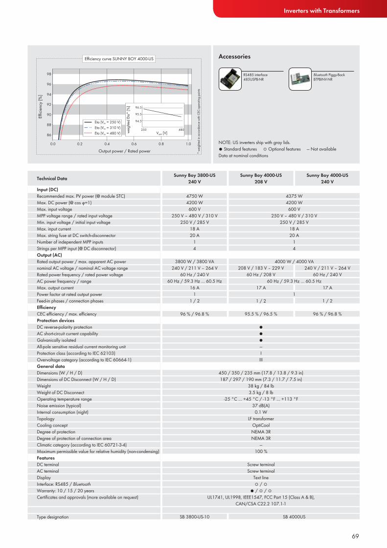
Inverters with Transformers
NOTE: US inverters ship with gray lids.● Standard features ○ Optional features — Not availableData at nominal conditions
Accessories
Input (DC)Recommended max. PV power (@ module STC)Max. DC power (@ cos ϕ=1)Max. input voltageMPP voltage range / rated input voltageMin. input voltage / initial input voltageMax. input currentMax. string fuse at DC switch-disconnectorNumber of independent MPP inputsStrings per MPP input (@ DC disconnector)Output (AC)Rated output power / max. apparent AC powernominal AC voltage / nominal AC voltage rangeRated power frequency / rated power voltageAC power frequency / range Max. output currentPower factor at rated output powerFeed-in phases / connection phasesEffi ciencyCEC effi ciency / max. effi ciencyProtection devicesDC reverse-polarity protectionAC short-circuit current capabilityGalvanically isolatedAll-pole sensitive residual current monitoring unitProtection class (according to IEC 62103)Overvoltage category (according to IEC 60664-1)General dataDimensions (W / H / D)Dimensions of DC Disconnect (W / H / D)WeightWeight of DC DisconnectOperating temperature rangeNoise emission (typical)Internal consumption (night)TopologyCooling conceptDegree of protectionDegree of protection of connection areaClimatic category (according to IEC 60721-3-4)Maximum permissible value for relative humidity (non-condensing)FeaturesDC terminalAC terminalDisplayInterface: RS485 / BluetoothWarranty: 10 / 15 / 20 yearsCertifi cates and approvals (more available on request)
Type designation
Technical Data Sunny Boy 4000-US208 V
Sunny Boy 3800-US240 V
69
RS485 interface 485USPB-NR
Bluetooth Piggy-BackBTPBINV-NR
Sunny Boy 4000-US240 V
4375 W4200 W600 V
250 V – 480 V / 310 V250 V / 285 V
18 A20 A
14
4750 W4200 W600 V
250 V – 480 V / 310 V250 V / 285 V
18 A20 A
14
3800 W / 3800 VA240 V / 211 V – 264 V
60 Hz / 240 V
16 A1
1 / 2
60 Hz / 59.3 Hz … 60.5 Hz
4000 W / 4000 VA
●●●—IIII
208 V / 183 V – 229 V60 Hz / 208 V
240 V / 211 V – 264 V60 Hz / 240 V
450 / 350 / 235 mm (17.8 / 13.8 / 9.3 in)187 / 297 / 190 mm (7.3 / 11.7 / 7.5 in)
38 kg / 84 lb3.5 kg / 8 lb
-25 °C … +45 °C / -13 °F … +113 °F37 dB(A)
0.1 WLF transformer
OptiCoolNEMA 3RNEMA 3R
—100 %
Screw terminalScrew terminal
Text line○ / ○
● / ○ / ○UL1741, UL1998, IEEE1547, FCC Part 15 (Class A & B),
CAN/CSA C22.2 107.1-1
SB 4000USSB 3800-US-10
60 Hz / 59.3 Hz … 60.5 Hz
117 A
1 / 2
95.5 % / 96.5 %
17 A
1 / 2
96 % / 96.8 %96 % / 96.8 %
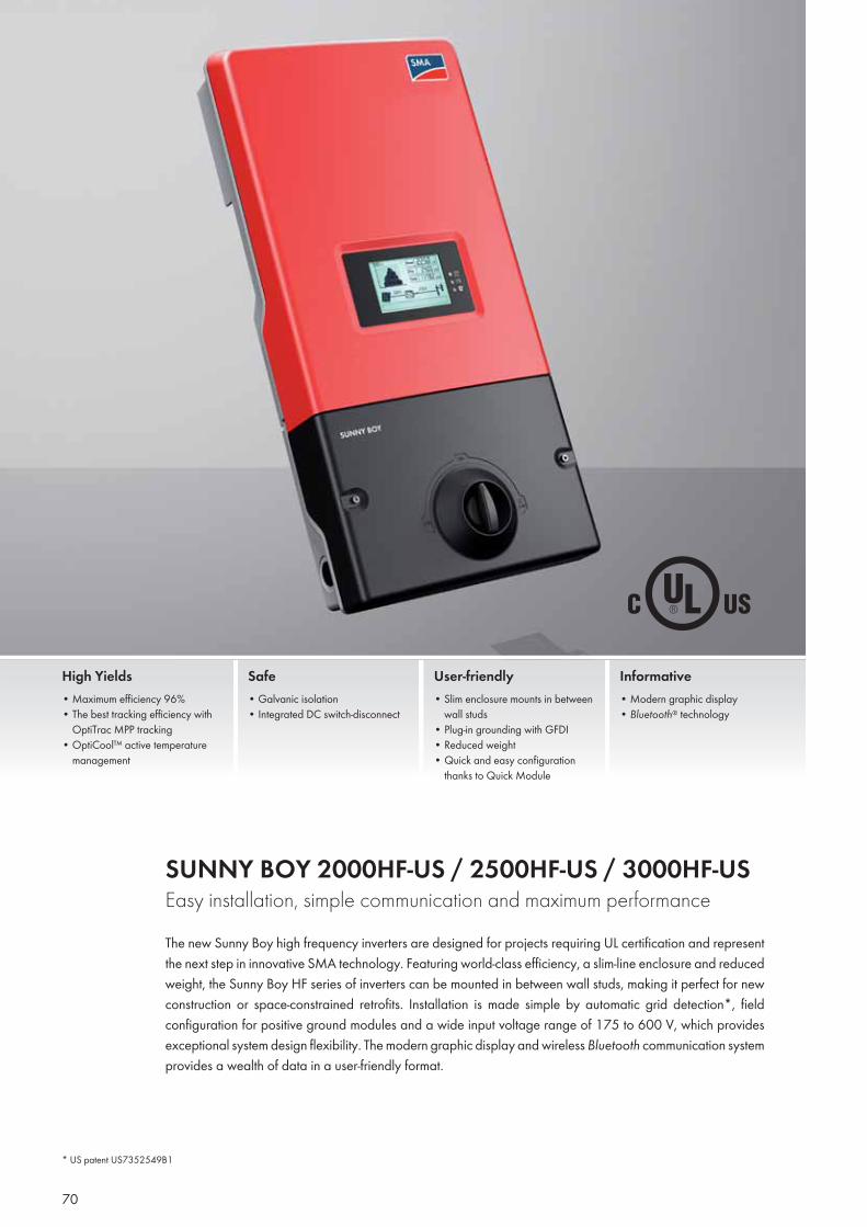
SUNNY BOY 2000HF-US / 2500HF-US / 3000HF-USEasy installation, simple communication and maximum performanceThe new Sunny Boy high frequency inverters are designed for projects requiring UL certification and represent the next step in innovative SMA technology. Featuring world-class efficiency, a slim-line enclosure and reduced weight, the Sunny Boy HF series of inverters can be mounted in between wall studs, making it perfect for new construction or space-constrained retrofits. Installation is made simple by automatic grid detection*, field configuration for positive ground modules and a wide input voltage range of 175 to 600 V, which provides exceptional system design flexibility. The modern graphic display and wireless Bluetooth communication system provides a wealth of data in a user-friendly format.
High Yields• Maximum efficiency 96%• The best tracking efficiency with
OptiTrac MPP tracking• OptiCool™ active temperature
management
Safe• Galvanic isolation• Integrated DC switch-disconnect
User-friendly• Slim enclosure mounts in between
wall studs• Plug-in grounding with GFDI• Reduced weight• Quick and easy configuration
thanks to Quick Module
Informative• Modern graphic display• Bluetooth® technology
* US patent US7352549B1
70
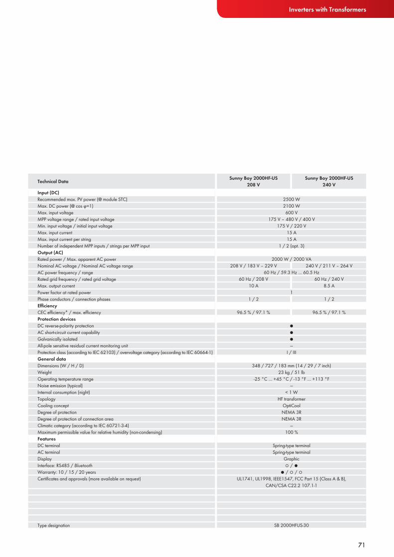
Inverters with Transformers
71
Input (DC)Recommended max. PV power (@ module STC)Max. DC power (@ cos ϕ=1)Max. input voltageMPP voltage range / rated input voltageMin. input voltage / initial input voltageMax. input currentMax. input current per stringNumber of independent MPP inputs / strings per MPP inputOutput (AC)Rated power / Max. apparent AC powerNominal AC voltage / Nominal AC voltage rangeAC power frequency / rangeRated grid frequency / rated grid voltageMax. output currentPower factor at rated powerPhase conductors / connection phasesEffi ciencyCEC effi ciency* / max. effi ciencyProtection devicesDC reverse-polarity protectionAC short-circuit current capabilityGalvanically isolatedAll-pole sensitive residual current monitoring unitProtection class (according to IEC 62103) / overvoltage category (according to IEC 60664-1)General dataDimensions (W / H / D)WeightOperating temperature rangeNoise emission (typical)Internal consumption (night)TopologyCooling conceptDegree of protectionDegree of protection of connection areaClimatic category (according to IEC 60721-3-4)Maximum permissible value for relative humidity (non-condensing)FeaturesDC terminalAC terminalDisplayInterface: RS485 / BluetoothWarranty: 10 / 15 / 20 yearsCertifi cates and approvals (more available on request)
Type designation
Technical Data Sunny Boy 2000HF-US208 V
Sunny Boy 2000HF-US240 V
71
2500 W2100 W600 V
175 V – 480 V / 400 V175 V / 220 V
15 A15 A
1 / 2 (opt. 3)
2000 W / 2000 VA
●●●—
I / III
208 V / 183 V – 229 V 240 V / 211 V – 264 V
348 / 727 / 183 mm (14 / 29 / 7 inch)23 kg / 51 lb
-25 °C … +45 °C / -13 °F … +113 °F—
< 1 WHF transformer
OptiCoolNEMA 3RNEMA 3R
—100 %
Spring-type terminalSpring-type terminal
Graphic○ / ●
● / ○ / ○ UL1741, UL1998, IEEE1547, FCC Part 15 (Class A & B),
CAN/CSA C22.2 107.1-1
SB 2000HFUS-30
60 Hz / 59.3 Hz … 60.5 Hz
1
60 Hz / 208 V10 A
1 / 2
96.5 % / 97.1 %
60 Hz / 240 V8.5 A
1 / 2
96.5 % / 97.1 %
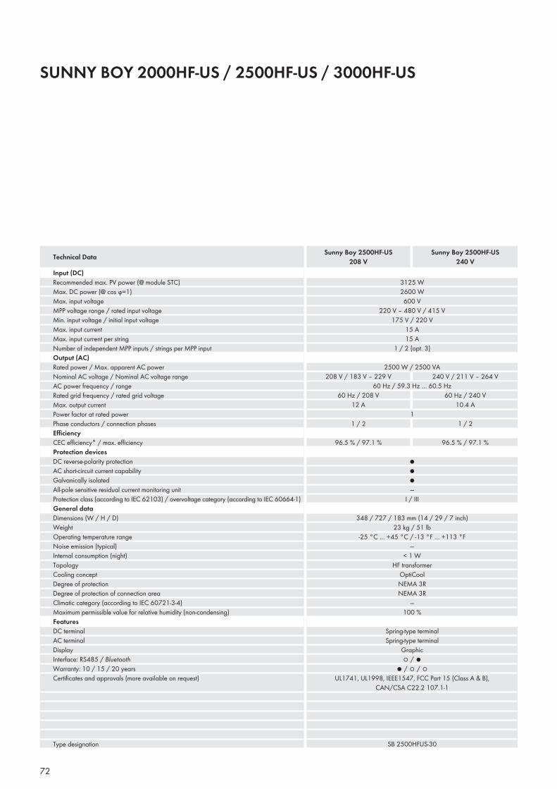
SUNNY BOY 2000HF-US / 2500HF-US / 3000HF-US
Input (DC)Recommended max. PV power (@ module STC)Max. DC power (@ cos ϕ=1)Max. input voltageMPP voltage range / rated input voltageMin. input voltage / initial input voltageMax. input currentMax. input current per stringNumber of independent MPP inputs / strings per MPP inputOutput (AC)Rated power / Max. apparent AC powerNominal AC voltage / Nominal AC voltage rangeAC power frequency / rangeRated grid frequency / rated grid voltageMax. output currentPower factor at rated powerPhase conductors / connection phasesEffi ciencyCEC effi ciency* / max. effi ciencyProtection devicesDC reverse-polarity protectionAC short-circuit current capabilityGalvanically isolatedAll-pole sensitive residual current monitoring unitProtection class (according to IEC 62103) / overvoltage category (according to IEC 60664-1)General dataDimensions (W / H / D)WeightOperating temperature rangeNoise emission (typical)Internal consumption (night)TopologyCooling conceptDegree of protectionDegree of protection of connection areaClimatic category (according to IEC 60721-3-4)Maximum permissible value for relative humidity (non-condensing)FeaturesDC terminalAC terminalDisplayInterface: RS485 / BluetoothWarranty: 10 / 15 / 20 yearsCertifi cates and approvals (more available on request)
Type designation
Technical Data Sunny Boy 2500HF-US208 V
72
Sunny Boy 2500HF-US240 V
3125 W2600 W600 V
220 V – 480 V / 415 V175 V / 220 V
15 A15 A
1 / 2 (opt. 3)
2500 W / 2500 VA
●●●—
I / III
208 V / 183 V – 229 V 240 V / 211 V – 264 V
348 / 727 / 183 mm (14 / 29 / 7 inch)23 kg / 51 lb
-25 °C … +45 °C / -13 °F … +113 °F—
< 1 WHF transformer
OptiCoolNEMA 3RNEMA 3R
—100 %
Spring-type terminalSpring-type terminal
Graphic○ / ●
● / ○ / ○ UL1741, UL1998, IEEE1547, FCC Part 15 (Class A & B),
CAN/CSA C22.2 107.1-1
SB 2500HFUS-30
60 Hz / 59.3 Hz … 60.5 Hz
1
60 Hz / 208 V12 A
1 / 2
96.5 % / 97.1 %
60 Hz / 240 V10.4 A
1 / 2
96.5 % / 97.1 %
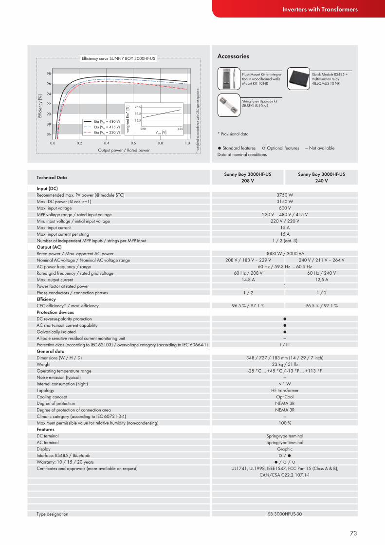
Inverters with Transformers
● Standard features ○ Optional features — Not availableData at nominal conditions
Accessories
Input (DC)Recommended max. PV power (@ module STC)Max. DC power (@ cos ϕ=1)Max. input voltageMPP voltage range / rated input voltageMin. input voltage / initial input voltageMax. input currentMax. input current per stringNumber of independent MPP inputs / strings per MPP inputOutput (AC)Rated power / Max. apparent AC powerNominal AC voltage / Nominal AC voltage rangeAC power frequency / rangeRated grid frequency / rated grid voltageMax. output currentPower factor at rated powerPhase conductors / connection phasesEffi ciencyCEC effi ciency* / max. effi ciencyProtection devicesDC reverse-polarity protectionAC short-circuit current capabilityGalvanically isolatedAll-pole sensitive residual current monitoring unitProtection class (according to IEC 62103) / overvoltage category (according to IEC 60664-1)General dataDimensions (W / H / D)WeightOperating temperature rangeNoise emission (typical)Internal consumption (night)TopologyCooling conceptDegree of protectionDegree of protection of connection areaClimatic category (according to IEC 60721-3-4)Maximum permissible value for relative humidity (non-condensing)FeaturesDC terminalAC terminalDisplayInterface: RS485 / BluetoothWarranty: 10 / 15 / 20 yearsCertifi cates and approvals (more available on request)
Type designation
Technical Data Sunny Boy 3000HF-US208 V
73
Flush-Mount Kit for integra-tion in wood-framed walls Mount KIT-10-NR
Quick Module RS485 + multi-function relay 485QMUS-10-NR
Sunny Boy 3000HF-US240 V
3750 W3150 W600 V
220 V – 480 V / 415 V220 V / 220 V
15 A15 A
1 / 2 (opt. 3)
3000 W / 3000 VA
●●●—
I / III
208 V / 183 V – 229 V 240 V / 211 V – 264 V
348 / 727 / 183 mm (14 / 29 / 7 inch)23 kg / 51 lb
-25 °C … +45 °C / -13 °F … +113 °F—
< 1 WHF transformer
OptiCoolNEMA 3RNEMA 3R
—100 %
Spring-type terminalSpring-type terminal
Graphic○ / ●
● / ○ / ○ UL1741, UL1998, IEEE1547, FCC Part 15 (Class A & B),
CAN/CSA C22.2 107.1-1
SB 3000HFUS-30
60 Hz / 59.3 Hz … 60.5 Hz
1
60 Hz / 208 V14.8 A
1 / 2
96.5 % / 97.1 %
60 Hz / 240 V12,5 A
1 / 2
96.5 % / 97.1 %
* Provisional data
String fuses Upgrade kitSB-SFK-US-10-NR
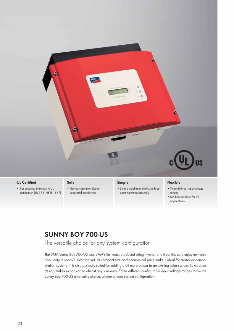
74
SUNNY BOY 700-USThe versatile choice for any system configurationThe SMA Sunny Boy 700-US was SMA’s first mass-produced string inverter and it continues to enjoy immense popularity in today’s solar market. Its compact size and economical price make it ideal for starter or demon-stration systems. It is also perfectly suited for adding a bit more power to an existing solar system. Its modular design makes expansion to almost any size easy. Three different configurable input voltage ranges make the Sunny Boy 700-US a versatile choice, whatever your system configuration.
UL Certified• For countries that require UL
certification (UL 1741/IEEE 1547)
Safe• Galvanic isolation due to
integrated transformer
Simple• Simple installation thanks to three-
point mounting assembly
Flexible• Three different input voltage
ranges• Modular addition for all
applications
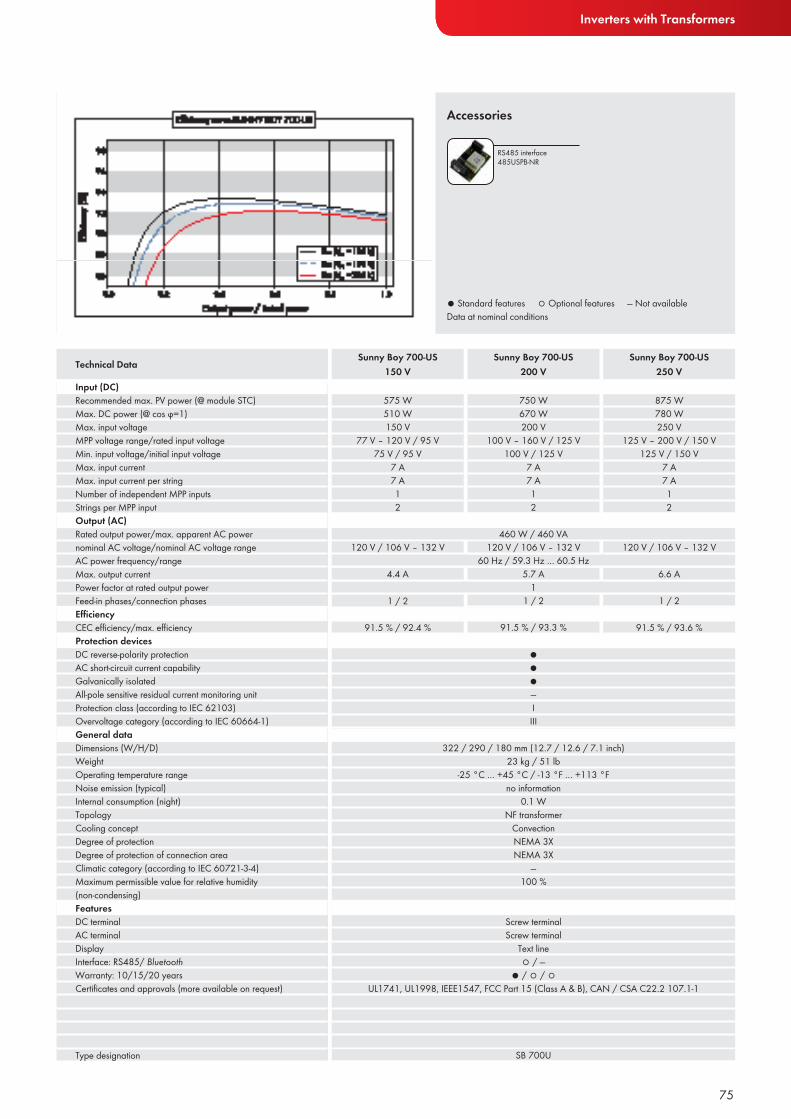
Inverters with Transformers
● Standard features ○ Optional features — Not availableData at nominal conditions
Accessories
Input (DC)Recommended max. PV power (@ module STC)Max. DC power (@ cos ϕ=1)Max. input voltageMPP voltage range/rated input voltageMin. input voltage/initial input voltageMax. input currentMax. input current per stringNumber of independent MPP inputsStrings per MPP inputOutput (AC)Rated output power/max. apparent AC powernominal AC voltage/nominal AC voltage rangeAC power frequency/rangeMax. output currentPower factor at rated output powerFeed-in phases/connection phasesEffi ciencyCEC effi ciency/max. effi ciencyProtection devicesDC reverse-polarity protectionAC short-circuit current capabilityGalvanically isolatedAll-pole sensitive residual current monitoring unitProtection class (according to IEC 62103)Overvoltage category (according to IEC 60664-1)General dataDimensions (W/H/D)WeightOperating temperature rangeNoise emission (typical)Internal consumption (night)TopologyCooling conceptDegree of protectionDegree of protection of connection areaClimatic category (according to IEC 60721-3-4)Maximum permissible value for relative humidity(non-condensing)FeaturesDC terminalAC terminalDisplayInterface: RS485/ BluetoothWarranty: 10/15/20 yearsCertifi cates and approvals (more available on request)
Type designation
Technical Data Sunny Boy 700-US 150 V
Sunny Boy 700-US250 V
Sunny Boy 700-US200 V
RS485 interface 485USPB-NR
75
575 W510 W150 V
77 V – 120 V / 95 V75 V / 95 V
7 A7 A12
460 W / 460 VA
●●●—I III
120 V / 106 V – 132 V
750 W670 W200 V
100 V – 160 V / 125 V100 V / 125 V
7 A7 A12
875 W780 W250 V
125 V – 200 V / 150 V125 V / 150 V
7 A7 A12
322 / 290 / 180 mm (12.7 / 12.6 / 7.1 inch)23 kg / 51 lb
-25 °C … +45 °C / -13 °F … +113 °Fno information
0.1 WNF transformer
ConvectionNEMA 3XNEMA 3X
—100 %
Screw terminalScrew terminal
Text line○ / —
● / ○ / ○UL1741, UL1998, IEEE1547, FCC Part 15 (Class A & B), CAN / CSA C22.2 107.1-1
SB 700U
60 Hz / 59.3 Hz … 60.5 Hz
14.4 A
1 / 2
91.5 % / 92.4 %
5.7 A
1 / 2
91.5 % / 93.3 %
6.6 A
1 / 2
91.5 % / 93.6 %
120 V / 106 V – 132 V 120 V / 106 V – 132 V

76
SUNNY TOWER
76

7777
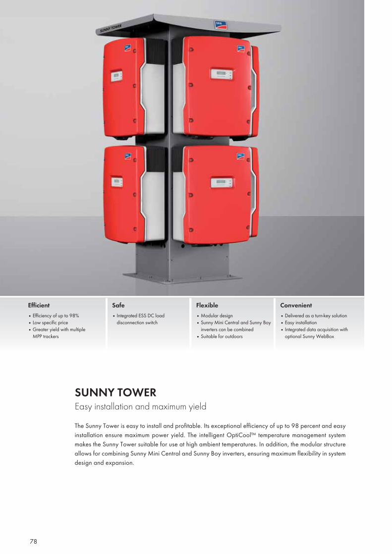
SUNNY TOWER Easy installation and maximum yieldThe Sunny Tower is easy to install and profitable. Its exceptional efficiency of up to 98 percent and easy installation ensure maximum power yield. The intelligent OptiCool™ temperature management system makes the Sunny Tower suitable for use at high ambient temperatures. In addition, the modular structure allows for combining Sunny Mini Central and Sunny Boy inverters, ensuring maximum flexibility in system design and expansion.
Efficient• Efficiency of up to 98%• Low specific price• Greater yield with multiple
MPP trackers
Safe• Integrated ESS DC load
disconnection switch
Flexible• Modular design• Sunny Mini Central and Sunny Boy
inverters can be combined• Suitable for outdoors
Convenient• Delivered as a turn-key solution• Easy installation• Integrated data acquisition with
optional Sunny WebBox
78
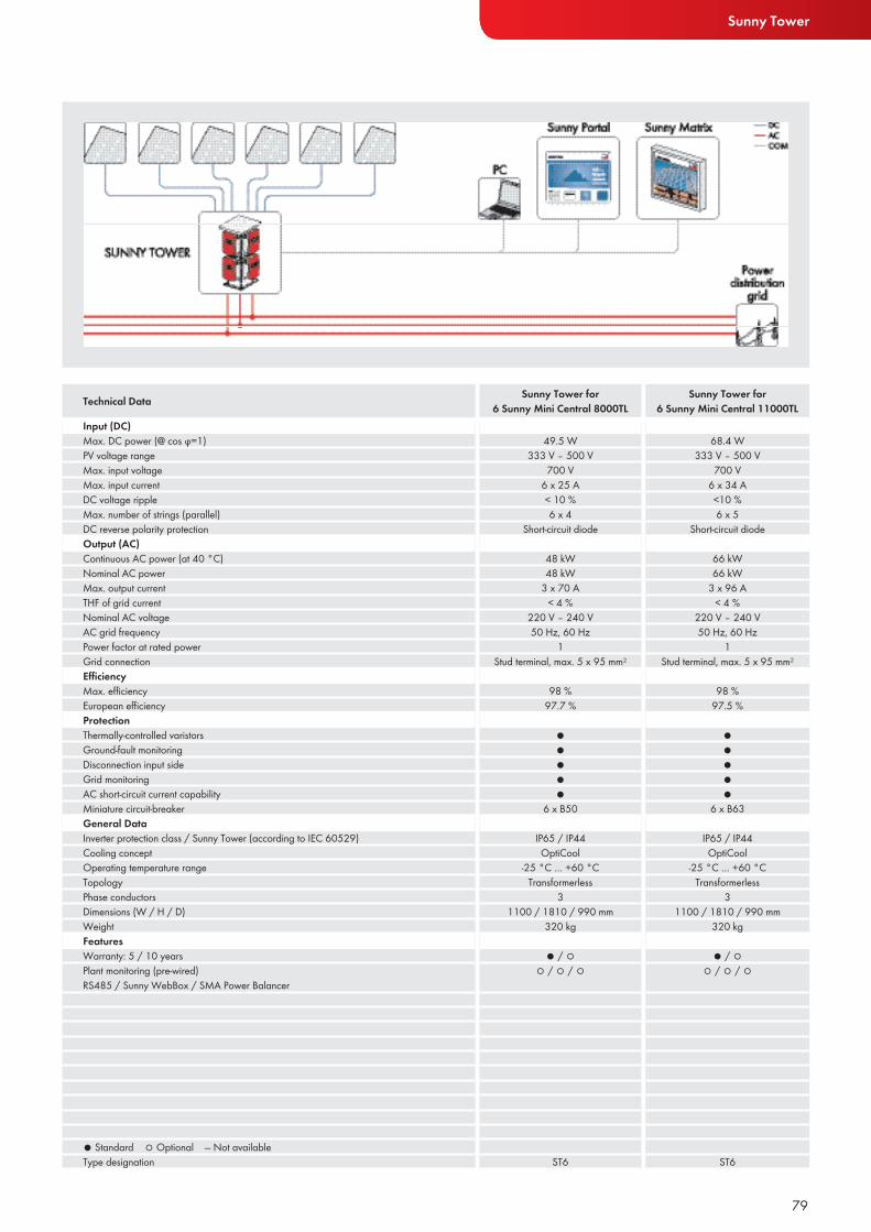
Sunny Tower
Input (DC)Max. DC power (@ cos ϕ=1)PV voltage rangeMax. input voltageMax. input currentDC voltage rippleMax. number of strings (parallel)DC reverse polarity protectionOutput (AC)Continuous AC power (at 40 °C)Nominal AC powerMax. output currentTHF of grid currentNominal AC voltageAC grid frequencyPower factor at rated powerGrid connectionEffi ciencyMax. effi ciency European effi ciency ProtectionThermally-controlled varistorsGround-fault monitoringDisconnection input sideGrid monitoringAC short-circuit current capabilityMiniature circuit-breakerGeneral DataInverter protection class / Sunny Tower (according to IEC 60529)Cooling conceptOperating temperature rangeTopologyPhase conductors Dimensions (W / H / D)WeightFeaturesWarranty: 5 / 10 yearsPlant monitoring (pre-wired)RS485 / Sunny WebBox / SMA Power Balancer
● Standard ○ Optional — Not availableType designation
Technical Data Sunny Tower for6 Sunny Mini Central 8000TL
Sunny Tower for 6 Sunny Mini Central 11000TL
79
49.5 W333 V – 500 V
700 V6 x 25 A< 10 %6 x 4
Short-circuit diode
48 kW48 kW
3 x 70 A < 4 %
220 V – 240 V50 Hz, 60 Hz
1Stud terminal, max. 5 x 95 mm2
98 %97.7 %
●●●●●
6 x B50
IP65 / IP44OptiCool
-25 °C … +60 °CTransformerless
31100 / 1810 / 990 mm
320 kg
● / ○○ / ○ / ○
ST6
68.4 W333 V – 500 V
700 V6 x 34 A<10 %6 x 5
Short-circuit diode
66 kW66 kW
3 x 96 A < 4 %
220 V – 240 V50 Hz, 60 Hz
1Stud terminal, max. 5 x 95 mm2
98 %97.5 %
●●●●●
6 x B63
IP65 / IP44OptiCool
-25 °C … +60 °CTransformerless
31100 / 1810 / 990 mm
320 kg
● / ○○ / ○ / ○
ST6
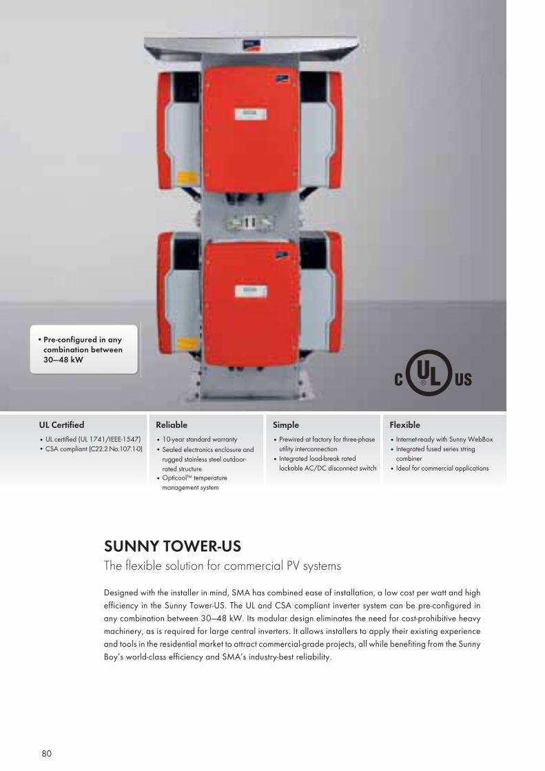
SUNNY TOWER-USThe flexible solution for commercial PV systemsDesigned with the installer in mind, SMA has combined ease of installation, a low cost per watt and high efficiency in the Sunny Tower-US. The UL and CSA compliant inverter system can be pre-configured in any combination between 30—48 kW. Its modular design eliminates the need for cost-prohibitive heavy machinery, as is required for large central inverters. It allows installers to apply their existing experience and tools in the residential market to attract commercial-grade projects, all while benefiting from the Sunny Boy’s world-class efficiency and SMA’s industry-best reliability.
UL Certified• UL certified (UL 1741/IEEE-1547)• CSA compliant (C22.2 No.107.1-0)
Reliable• 10-year standard warranty• Sealed electronics enclosure and
rugged stainless steel outdoor-rated structure
• Opticool™ temperature management system
Simple• Prewired at factory for three-phase
utility interconnection• Integrated load-break rated
lockable AC/DC disconnect switch
Flexible• Internet-ready with Sunny WebBox• Integrated fused series string
combiner• Ideal for commercial applications
80
• Pre-configured in any combination between 30—48 kW
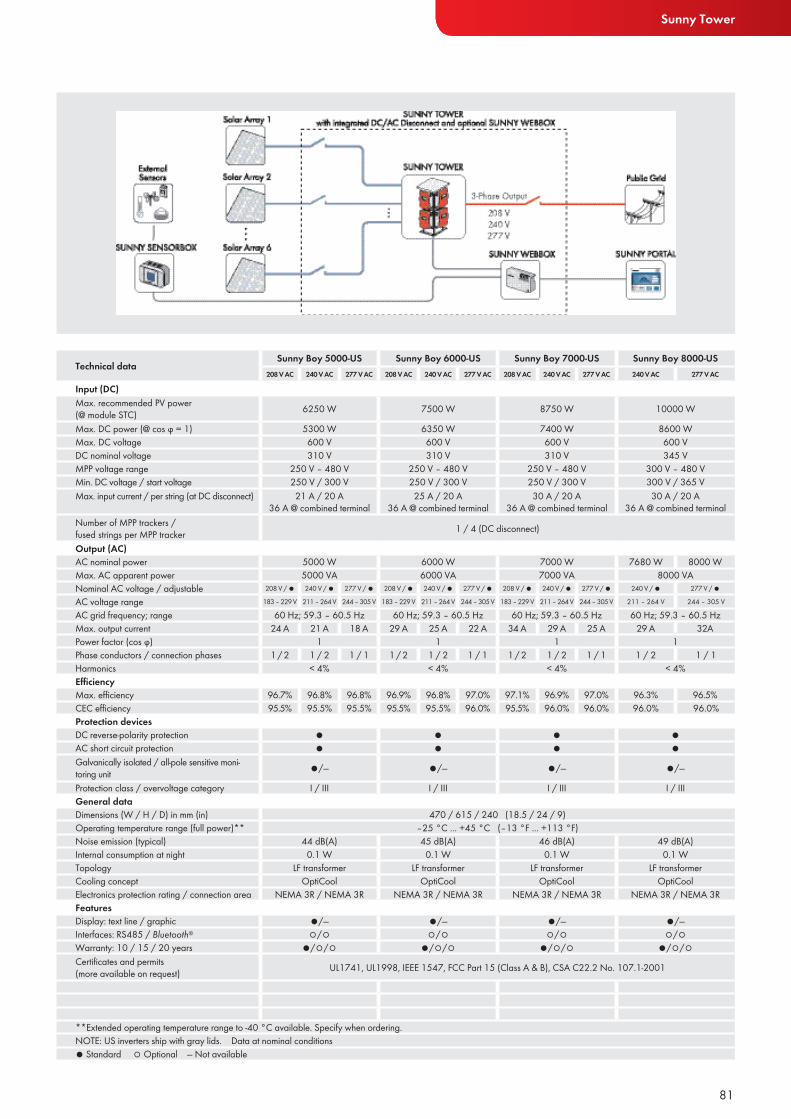
Technical data Sunny Boy 5000-US Sunny Boy 6000-US Sunny Boy 7000-US Sunny Boy 8000-US208 V AC 240 V AC 277 V AC 208 V AC 240 V AC 277 V AC 208 V AC 240 V AC 277 V AC 240 V AC 277 V AC
Input (DC)Max. recommended PV power (@ module STC) 6250 W 7500 W 8750 W 10000 WMax. DC power (@ cos ϕ = 1) 5300 W 6350 W 7400 W 8600 WMax. DC voltage 600 V 600 V 600 V 600 VDC nominal voltage 310 V 310 V 310 V 345 VMPP voltage range 250 V – 480 V 250 V – 480 V 250 V – 480 V 300 V – 480 VMin. DC voltage / start voltage 250 V / 300 V 250 V / 300 V 250 V / 300 V 300 V / 365 VMax. input current / per string (at DC disconnect) 21 A / 20 A
36 A @ combined terminal25 A / 20 A
36 A @ combined terminal30 A / 20 A
36 A @ combined terminal30 A / 20 A
36 A @ combined terminalNumber of MPP trackers / fused strings per MPP tracker 1 / 4 (DC disconnect)Output (AC)AC nominal power 5000 W 6000 W 7000 W 7680 W 8000 WMax. AC apparent power 5000 VA 6000 VA 7000 VA 8000 VANominal AC voltage / adjustable 208 V / ● 240 V / ● 277 V / ● 208 V / ● 240 V / ● 277 V / ● 208 V / ● 240 V / ● 277 V / ● 240 V / ● 277 V / ●AC voltage range 183 – 229 V 211 – 264 V 244 – 305 V 183 – 229 V 211 – 264 V 244 – 305 V 183 – 229 V 211 – 264 V 244 – 305 V 211 – 264 V 244 – 305 VAC grid frequency; range 60 Hz; 59.3 – 60.5 Hz 60 Hz; 59.3 – 60.5 Hz 60 Hz; 59.3 – 60.5 Hz 60 Hz; 59.3 – 60.5 HzMax. output current 24 A 21 A 18 A 29 A 25 A 22 A 34 A 29 A 25 A 29 A 32APower factor (cos ϕ) 1 1 1 1Phase conductors / connection phases 1 / 2 1 / 2 1 / 1 1 / 2 1 / 2 1 / 1 1 / 2 1 / 2 1 / 1 1 / 2 1 / 1Harmonics < 4% < 4% < 4% < 4%Effi ciencyMax. effi ciency 96.7% 96.8% 96.8% 96.9% 96.8% 97.0% 97.1% 96.9% 97.0% 96.3% 96.5%CEC effi ciency 95.5% 95.5% 95.5% 95.5% 95.5% 96.0% 95.5% 96.0% 96.0% 96.0% 96.0%Protection devicesDC reverse-polarity protection ● ● ● ●AC short circuit protection ● ● ● ●Galvanically isolated / all-pole sensitive moni-toring unit ●/— ●/— ●/— ●/—Protection class / overvoltage category I / III I / III I / III I / IIIGeneral dataDimensions (W / H / D) in mm (in) 470 / 615 / 240 (18.5 / 24 / 9)Operating temperature range (full power)** –25 °C ... +45 °C (–13 °F ... +113 °F)Noise emission (typical) 44 dB(A) 45 dB(A) 46 dB(A) 49 dB(A)Internal consumption at night 0.1 W 0.1 W 0.1 W 0.1 WTopology LF transformer LF transformer LF transformer LF transformerCooling concept OptiCool OptiCool OptiCool OptiCoolElectronics protection rating / connection area NEMA 3R / NEMA 3R NEMA 3R / NEMA 3R NEMA 3R / NEMA 3R NEMA 3R / NEMA 3RFeatures Display: text line / graphic ●/— ●/— ●/— ●/—Interfaces: RS485 / Bluetooth® ○/○ ○/○ ○/○ ○/○Warranty: 10 / 15 / 20 years ●/○/○ ●/○/○ ●/○/○ ●/○/○Certificates and permits (more available on request) UL1741, UL1998, IEEE 1547, FCC Part 15 (Class A & B), CSA C22.2 No. 107.1-2001
**Extended operating temperature range to -40 °C available. Specify when ordering.NOTE: US inverters ship with gray lids. Data at nominal conditions● Standard ○ Optional — Not available
Sunny Tower
81

82
BACKUP SYSTEMS
83
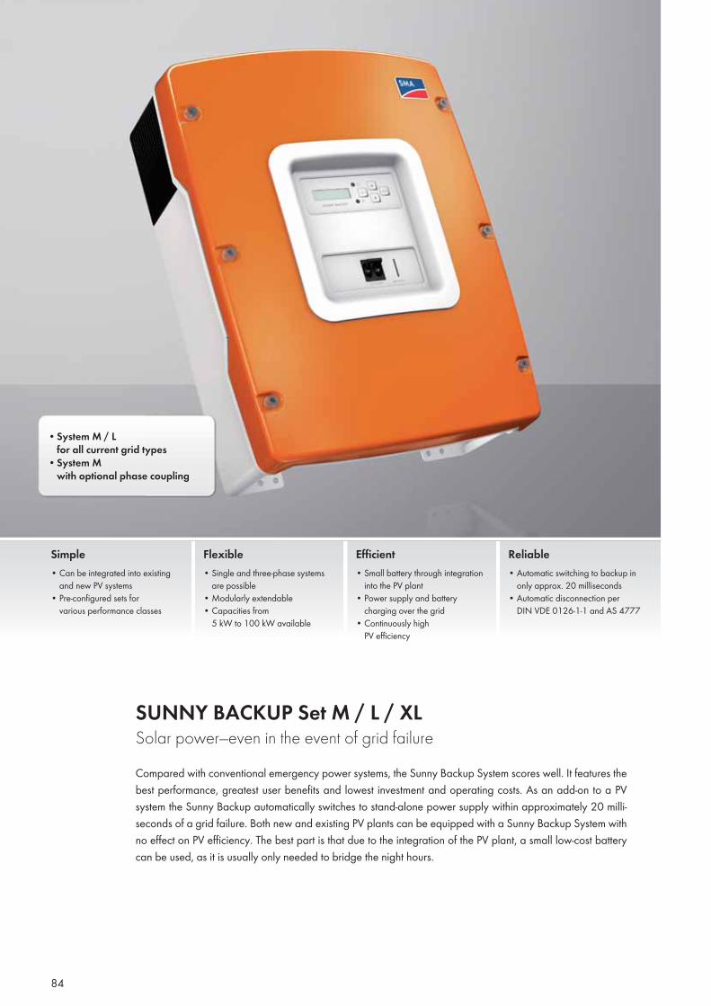
• System M / L for all current grid types• System M with optional phase coupling
SUNNY BACKUP Set M / L / XLSolar power—even in the event of grid failureCompared with conventional emergency power systems, the Sunny Backup System scores well. It features the best performance, greatest user benefits and lowest investment and operating costs. As an add-on to a PV system the Sunny Backup automatically switches to stand-alone power supply within approximately 20 milli-seconds of a grid failure. Both new and existing PV plants can be equipped with a Sunny Backup System with no effect on PV efficiency. The best part is that due to the integration of the PV plant, a small low-cost battery can be used, as it is usually only needed to bridge the night hours.
Simple• Can be integrated into existing
and new PV systems• Pre-configured sets for
various performance classes
Flexible• Single and three-phase systems
are possible• Modularly extendable• Capacities from
5 kW to 100 kW available
Efficient• Small battery through integration
into the PV plant • Power supply and battery
charging over the grid• Continuously high
PV efficiency
Reliable• Automatic switching to backup in
only approx. 20 milliseconds• Automatic disconnection per
DIN VDE 0126-1-1 and AS 4777
84
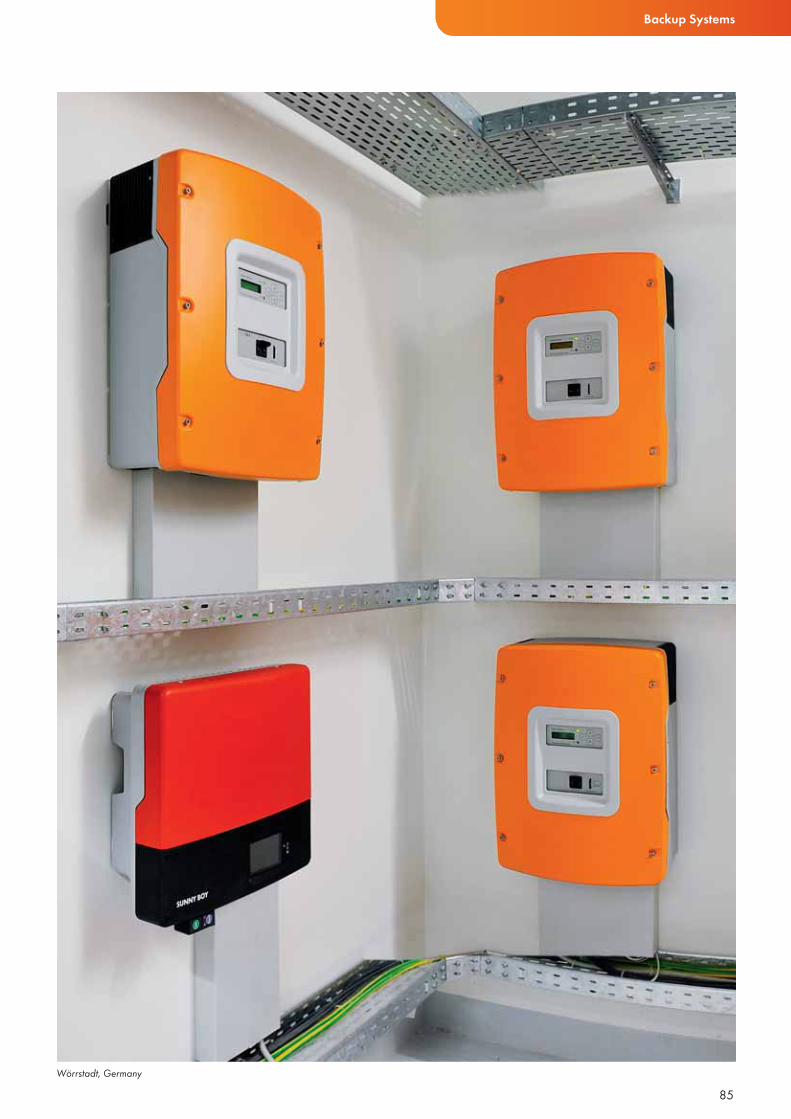
Backup Systems
85Wörrstadt, Germany
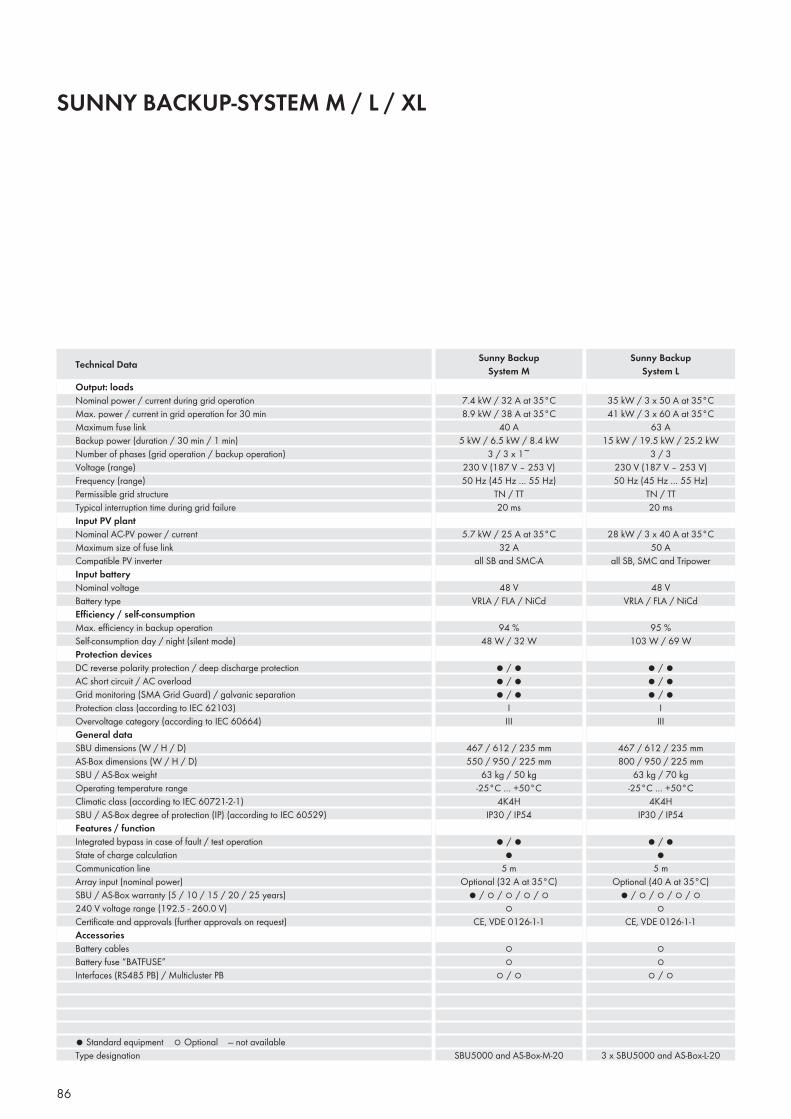
SUNNY BACKUP-SYSTEM M / L / XL
Output: loadsNominal power / current during grid operationMax. power / current in grid operation for 30 minMaximum fuse linkBackup power (duration / 30 min / 1 min)Number of phases (grid operation / backup operation) Voltage (range) Frequency (range) Permissible grid structureTypical interruption time during grid failureInput PV plantNominal AC-PV power / currentMaximum size of fuse linkCompatible PV inverterInput batteryNominal voltageBattery typeEffi ciency / self-consumptionMax. effi ciency in backup operationSelf-consumption day / night (silent mode)Protection devicesDC reverse polarity protection / deep discharge protection AC short circuit / AC overload Grid monitoring (SMA Grid Guard) / galvanic separation Protection class (according to IEC 62103)Overvoltage category (according to IEC 60664)General dataSBU dimensions (W / H / D)AS-Box dimensions (W / H / D)SBU / AS-Box weightOperating temperature rangeClimatic class (according to IEC 60721-2-1)SBU / AS-Box degree of protection (IP) (according to IEC 60529)Features / functionIntegrated bypass in case of fault / test operation State of charge calculationCommunication lineArray input (nominal power)SBU / AS-Box warranty (5 / 10 / 15 / 20 / 25 years)240 V voltage range (192.5 - 260.0 V)Certifi cate and approvals (further approvals on request)AccessoriesBattery cablesBattery fuse “BATFUSE”Interfaces (RS485 PB) / Multicluster PB
● Standard equipment ○ Optional — not availableType designation
Technical Data Sunny Backup System M
Sunny Backup System L
86
7.4 kW / 32 A at 35°C8.9 kW / 38 A at 35°C
40 A5 kW / 6.5 kW / 8.4 kW
3 / 3 x 1~ 230 V (187 V – 253 V)50 Hz (45 Hz … 55 Hz)
TN / TT20 ms
5.7 kW / 25 A at 35°C 32 A
all SB and SMC-A
48 VVRLA / FLA / NiCd
94 %48 W / 32 W
● / ● ● / ● ● / ●
IIII
467 / 612 / 235 mm550 / 950 / 225 mm
63 kg / 50 kg-25°C … +50°C
4K4HIP30 / IP54
● / ● ●
5 mOptional (32 A at 35°C)
● / ○ / ○ / ○ / ○○
CE, VDE 0126-1-1
○○
○ / ○
SBU5000 and AS-Box-M-20
35 kW / 3 x 50 A at 35°C41 kW / 3 x 60 A at 35°C
63 A15 kW / 19.5 kW / 25.2 kW
3 / 3 230 V (187 V – 253 V)50 Hz (45 Hz … 55 Hz)
TN / TT20 ms
28 kW / 3 x 40 A at 35°C 50 A
all SB, SMC and Tripower
48 VVRLA / FLA / NiCd
95 %103 W / 69 W
● / ● ● / ● ● / ●
IIII
467 / 612 / 235 mm800 / 950 / 225 mm
63 kg / 70 kg-25°C … +50°C
4K4HIP30 / IP54
● / ● ●
5 mOptional (40 A at 35°C)
● / ○ / ○ / ○ / ○○
CE, VDE 0126-1-1
○○
○ / ○
3 x SBU5000 and AS-Box-L-20
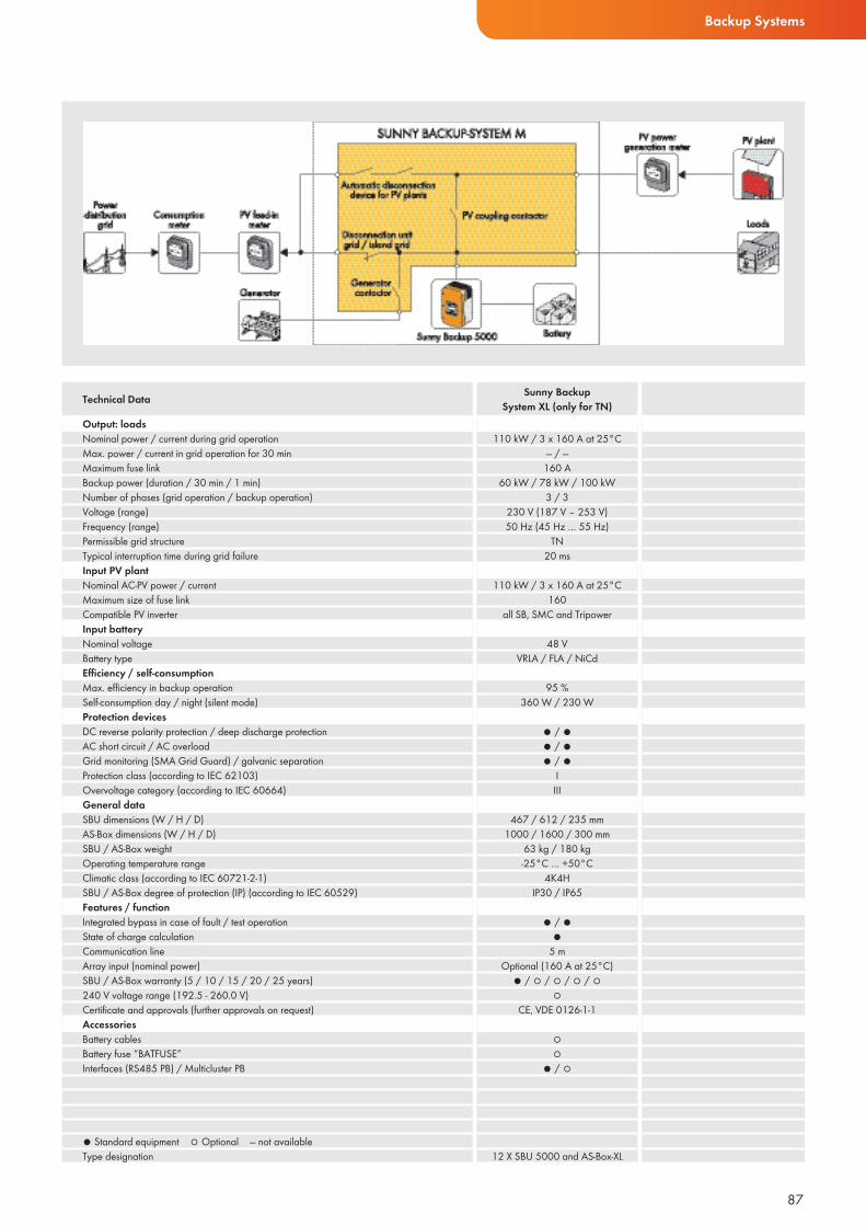
Backup Systems
Output: loadsNominal power / current during grid operationMax. power / current in grid operation for 30 minMaximum fuse linkBackup power (duration / 30 min / 1 min)Number of phases (grid operation / backup operation) Voltage (range) Frequency (range) Permissible grid structureTypical interruption time during grid failureInput PV plantNominal AC-PV power / currentMaximum size of fuse linkCompatible PV inverterInput batteryNominal voltageBattery typeEffi ciency / self-consumptionMax. effi ciency in backup operationSelf-consumption day / night (silent mode)Protection devicesDC reverse polarity protection / deep discharge protection AC short circuit / AC overload Grid monitoring (SMA Grid Guard) / galvanic separation Protection class (according to IEC 62103)Overvoltage category (according to IEC 60664)General dataSBU dimensions (W / H / D)AS-Box dimensions (W / H / D)SBU / AS-Box weightOperating temperature rangeClimatic class (according to IEC 60721-2-1)SBU / AS-Box degree of protection (IP) (according to IEC 60529)Features / functionIntegrated bypass in case of fault / test operation State of charge calculationCommunication lineArray input (nominal power)SBU / AS-Box warranty (5 / 10 / 15 / 20 / 25 years)240 V voltage range (192.5 - 260.0 V)Certifi cate and approvals (further approvals on request)AccessoriesBattery cablesBattery fuse “BATFUSE”Interfaces (RS485 PB) / Multicluster PB
● Standard equipment ○ Optional — not availableType designation
Technical Data Sunny BackupSystem XL (only for TN)
87
110 kW / 3 x 160 A at 25°C— / —160 A
60 kW / 78 kW / 100 kW3 / 3
230 V (187 V – 253 V)50 Hz (45 Hz … 55 Hz)
TN20 ms
110 kW / 3 x 160 A at 25°C 160
all SB, SMC and Tripower
48 VVRLA / FLA / NiCd
95 %360 W / 230 W
● / ● ● / ● ● / ●
IIII
467 / 612 / 235 mm1000 / 1600 / 300 mm
63 kg / 180 kg-25°C … +50°C
4K4HIP30 / IP65
● / ● ●
5 mOptional (160 A at 25°C)
● / ○ / ○ / ○ / ○○
CE, VDE 0126-1-1
○○
● / ○
12 X SBU 5000 and AS-Box-XL
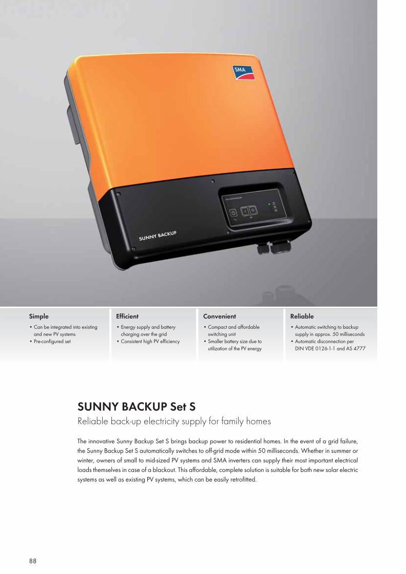
SUNNY BACKUP Set SReliable back-up electricity supply for family homesThe innovative Sunny Backup Set S brings backup power to residential homes. In the event of a grid failure, the Sunny Backup Set S automatically switches to off-grid mode within 50 milliseconds. Whether in summer or winter, owners of small to mid-sized PV systems and SMA inverters can supply their most important electrical loads themselves in case of a blackout. This affordable, complete solution is suitable for both new solar electric systems as well as existing PV systems, which can be easily retrofitted.
Simple• Can be integrated into existing
and new PV systems• Pre-configured set
Efficient• Energy supply and battery
charging over the grid• Consistent high PV efficiency
Convenient• Compact and affordable
switching unit• Smaller battery size due to
utilization of the PV energy
Reliable• Automatic switching to backup
supply in approx. 50 milliseconds• Automatic disconnection per
DIN VDE 0126-1-1 and AS 4777
88
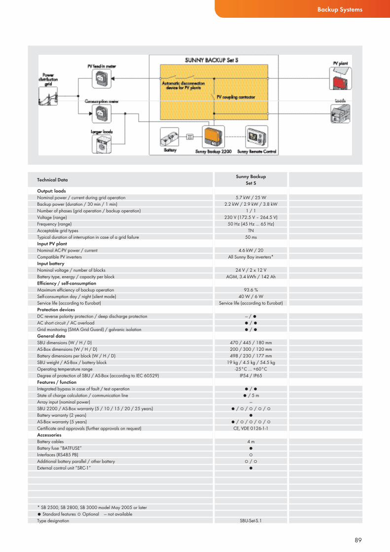
Backup Systems
Output: loadsNominal power / current during grid operationBackup power (duration / 30 min / 1 min)Number of phases (grid operation / backup operation) Voltage (range)Frequency (range) Acceptable grid typesTypical duration of interruption in case of a grid failureInput PV plantNominal AC-PV power / current Compatible PV invertersInput batteryNominal voltage / number of blocksBattery type, energy / capacity per blockEffi ciency / self-consumptionMaximum effi ciency of backup operationSelf-consumption day / night (silent mode)Service life (according to Eurobat)Protection devicesDC reverse polarity protection / deep discharge protection AC short circuit / AC overload Grid monitoring (SMA Grid Guard) / galvanic isolation General dataSBU dimensions (W / H / D)AS-Box dimensions (W / H / D)Battery dimensions per block (W / H / D)SBU weight / AS-Box / battery blockOperating temperature rangeDegree of protection of SBU / AS-Box (according to IEC 60529)Features / functionIntegrated bypass in case of fault / test operation State of charge calculation / communication lineArray input (nominal power)SBU 2200 / AS-Box warranty (5 / 10 / 15 / 20 / 25 years)Battery warranty (2 years)AS-Box warranty (5 years)Certifi cate and approvals (further approvals on request)AccessoriesBattery cablesBattery fuse “BATFUSE”Interfaces (RS485 PB)Additional battery parallel / other batteryExternal control unit “SRC-1”
* SB 2500, SB 2800, SB 3000 model May 2005 or later● Standard features ○ Optional — not availableType designation
Technical Data Sunny Backup Set S
89
5.7 kW / 25 W2.2 kW / 2.9 kW / 3.8 kW
1 / 1 230 V (172.5 V – 264.5 V)
50 Hz (45 Hz … 65 Hz) TN
50 ms
4.6 kW / 20 All Sunny Boy inverters*
24 V / 2 x 12 VAGM, 3.4 kWh / 142 Ah
93.6 %40 W / 6 W
Service life (according to Eurobat)
— / ● ● / ●● / ●
470 / 445 / 180 mm200 / 300 / 120 mm498 / 230 / 177 mm
19 kg / 4.5 kg / 54.5 kg-25°C … +60°C
IP54 / IP65
● / ● ● / 5 m
—● / ○ / ○ / ○ / ○
●● / ○ / ○ / ○ / ○CE, VDE 0126-1-1
4 m●○
○ / ○●
SBU-Set-S.1
CENTRAL INVERTERS
90
91
92
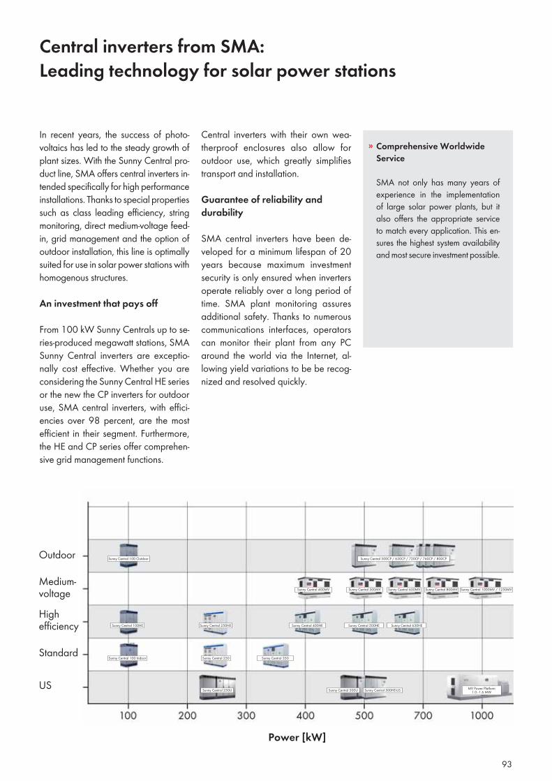
Central inverters from SMA:Leading technology for solar power stations
Central inverters with their own wea-therproof enclosures also allow for outdoor use, which greatly simplifies transport and installation.
Guarantee of reliability and durability
SMA central inverters have been de-veloped for a minimum lifespan of 20 years because maximum investment security is only ensured when inverters operate reliably over a long period of time. SMA plant monitoring assures additional safety. Thanks to numerous communications interfaces, operators can monitor their plant from any PC around the world via the Internet, al-lowing yield variations to be be recog-nized and resolved quickly.
In recent years, the success of photo-voltaics has led to the steady growth of plant sizes. With the Sunny Central pro-duct line, SMA offers central inverters in-tended specifically for high performance installations. Thanks to special properties such as class leading efficiency, string monitoring, direct medium-voltage feed-in, grid management and the option of outdoor installation, this line is optimally suited for use in solar power stations with homogenous structures.
An investment that pays off
From 100 kW Sunny Centrals up to se-ries-produced megawatt stations, SMA Sunny Central inverters are exceptio-nally cost effective. Whether you are considering the Sunny Central HE series or the new the CP inverters for outdoor use, SMA central inverters, with effici-encies over 98 percent, are the most efficient in their segment. Furthermore, the HE and CP series offer comprehen-sive grid management functions.
Sunny Central 1000MV / 1250MVSunny Central 630MV Sunny Central 800MVSunny Central 500MVSunny Central 400MV
Sunny Central 500HE Sunny Central 630HE
Sunny Central 350
Sunny Central 100 Outdoor Sunny Central 500CP / 630CP / 720CP / 760CP / 800CP
Sunny Central 250U Sunny Central 500U Sunny Central 500HE-US MV Power Platform1.0–1.6 MW
Sunny Central 400HESunny Central 250HE
Sunny Central 250Sunny Central 100 Indoor
Sunny Central 100HE
Power [kW]
Medium-voltageHighefficiency
Standard
Outdoor
US
» Comprehensive Worldwide Service
SMA not only has many years of experience in the implementation of large solar power plants, but it also offers the appropriate service to match every application. This en-sures the highest system availability and most secure investment possible.
93
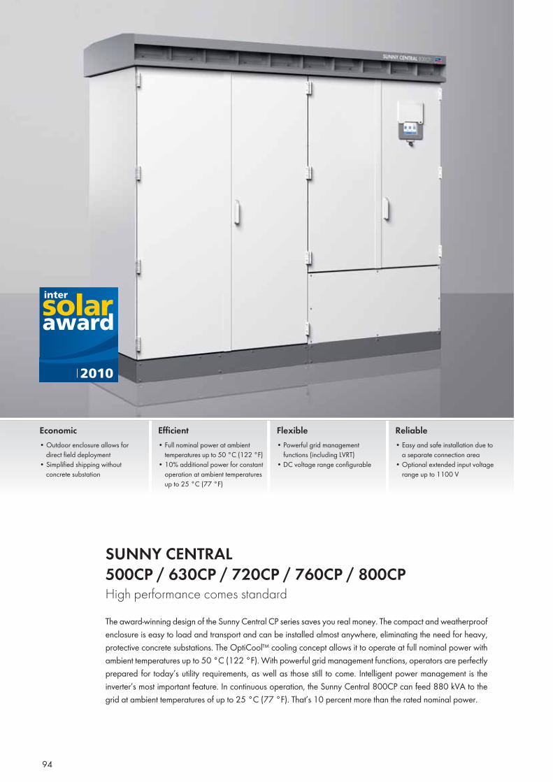
94
SUNNY CENTRAL 500CP / 630CP / 720CP / 760CP / 800CP High performance comes standardThe award-winning design of the Sunny Central CP series saves you real money. The compact and weatherproof enclosure is easy to load and transport and can be installed almost anywhere, eliminating the need for heavy, protective concrete substations. The OptiCool™ cooling concept allows it to operate at full nominal power with ambient temperatures up to 50 °C (122 °F). With powerful grid management functions, operators are perfectly prepared for today’s utility requirements, as well as those still to come. Intelligent power management is the inverter’s most important feature. In continuous operation, the Sunny Central 800CP can feed 880 kVA to the grid at ambient temperatures of up to 25 °C (77 °F). That’s 10 percent more than the rated nominal power.
Economic• Outdoor enclosure allows for
direct field deployment • Simplified shipping without
concrete substation
Efficient• Full nominal power at ambient
temperatures up to 50 °C (122 °F)• 10% additional power for constant
operation at ambient temperatures up to 25 °C (77 °F)
Flexible• Powerful grid management
functions (including LVRT)• DC voltage range configurable
Reliable• Easy and safe installation due to
a separate connection area• Optional extended input voltage
range up to 1100 V
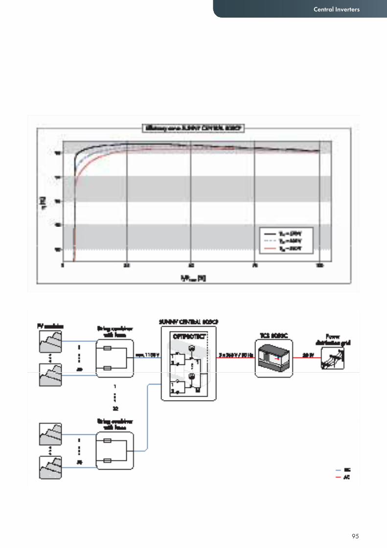
95
Central Inverters
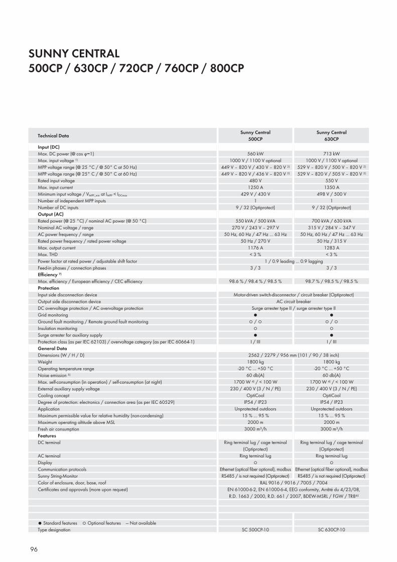
96
SUNNY CENTRAL 500CP / 630CP / 720CP / 760CP / 800CP
Input (DC)Max. DC power (@ cos ϕ=1)Max. input voltage 1)
MPP voltage range (@ 25 °C / @ 50° C at 50 Hz)MPP voltage range (@ 25° C / @ 50° C at 60 Hz)Rated input voltageMax. input currentMinimum input voltage / VMPP_min at IMPP < IDCmaxNumber of independent MPP inputsNumber of DC inputsOutput (AC)Rated power (@ 25 °C) / nominal AC power (@ 50 °C) Nominal AC voltage / rangeAC power frequency / rangeRated power frequency / rated power voltageMax. output currentMax. THDPower factor at rated power / adjustable shift factorFeed-in phases / connection phasesEffi ciency 7)
Max. effi ciency / European effi ciency / CEC effi ciencyProtectionInput side disconnection deviceOutput side disconnection deviceDC overvoltage protection / AC overvoltage protectionGrid monitoringGround fault monitoring / Remote ground fault monitoringInsulation monitoringSurge arrester for auxiliary supplyProtection class (as per IEC 62103) / overvoltage category (as per IEC 60664-1)General DataDimensions (W / H / D)WeightOperating temperature rangeNoise emission 5)
Max. self-consumption (in operation) / self-consumption (at night)External auxiliary supply voltageCooling conceptDegree of protection: electronics / connection area (as per IEC 60529)ApplicationMaximum permissible value for relative humidity (non-condensing)Maximum operating altitude above MSLFresh air consumptionFeaturesDC terminal
AC terminalDisplayCommunication protocolsSunny String-MonitorColor of enclosure, door, base, roofCertifi cates and approvals (more upon request)
● Standard features ○ Optional features — Not availableType designation
Technical Data Sunny Central500CP
Sunny Central630CP
560 kW1000 V / 1100 V optional
449 V – 820 V / 430 V – 820 V 2)
449 V – 820 V / 436 V – 820 V 2)
480 V1250 A
429 V / 430 V1
9 / 32 (Optiprotect)
550 kVA / 500 kVA270 V / 243 V – 297 V
50 Hz, 60 Hz / 47 Hz … 63 Hz50 Hz / 270 V
1176 A< 3 %
713 kW1000 V / 1100 V optional
529 V – 820 V / 500 V – 820 V 2)
529 V – 820 V / 505 V – 820 V 2)
550 V1350 A
498 V / 500 V1
9 / 32 (Optiprotect)
700 kVA / 630 kVA315 V / 284 V – 347 V
50 Hz, 60 Hz / 47 Hz … 63 Hz50 Hz / 315 V
1283 A< 3 %
1 / 0.9 leading ... 0.9 lagging3 / 3 3 / 3
Motor-driven switch-disconnector / circuit breaker (Optiprotect)AC circuit breaker
Surge arrester type II / surge arrester type II
98.6 % / 98.4 % / 98.5 %
●○ / ○
○●
I / III
2562 / 2279 / 956 mm (101 / 90 / 38 inch)1800 kg
-20 °C … +50 °C60 db(A)
1700 W 4) / < 100 W230 / 400 V (3 / N / PE)
OptiCoolIP54 / IP23
Unprotected outdoors15 % … 95 %
2000 m3000 m³/h
Ring terminal lug / cage terminal (Optiprotect)
Ring terminal lug○
Ethernet (optical fi ber optional), modbusRS485 / is not required (Optiprotect)
RAL 9016 / 9016 / 7005 / 7004EN 61000-6-2, EN 61000-6-4, EEG conformity, Arrêté du 4/23/08, R.D. 1663 / 2000, R.D. 661 / 2007, BDEW-MSRL / FGW / TR8⁶⁾
SC 500CP-10
●○ / ○
○●
I / III
98.7 % / 98.5 % / 98.5 %
1800 kg-20 °C … +50 °C
60 db(A)1700 W 4) / < 100 W
230 / 400 V (3 / N / PE)OptiCool
IP54 / IP23Unprotected outdoors
15 % … 95 %2000 m
3000 m³/h
Ring terminal lug / cage terminal (Optiprotect)
Ring terminal lug○
Ethernet (optical fi ber optional), modbusRS485 / is not required (Optiprotect)
SC 630CP-10
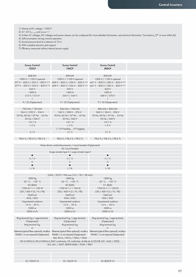
97
Central Inverters
Sunny Central720CP
Sunny Central760CP
Sunny Central800CP
1) Startup at DC voltage < 1000 V2) At 1.05 VAC, nom and cos ϕ = 13) Further AC voltages, DC voltages and power classes can be configured (for more detailed information, see technical information “Innovations_CP” at www.SMA.de)4) Self-consumption during nominal operation5) Sound pressure level at a distance of 10 m6) With complete dynamic grid support7) Efficiency measured without internal power supply
808 kW1000 V / 1100 V optional
577 V – 820 V / 525 V – 820 V 2) 3)
577 V – 820 V / 525 V – 820 V 2) 3)
565 V1400 A
515 V / 515 V1
9 / 32 (Optiprotect)
792 kVA / 720 kVA324 V / 292 V – 356 V
50 Hz, 60 Hz / 47 Hz … 63 Hz50 Hz / 324 V
1411 A< 3 %
898 kW1000 V / 1100 V optional
609 V – 820 V / 554 V – 820 V 2) 3)
609 V – 820 V / 554 V – 820 V 2) 3)
595 V1400 A
545 V / 545 V1
9 / 32 (Optiprotect)
836 kVA / 760 kVA342 V / 308 V – 376 V
50 Hz, 60 Hz / 47 Hz … 63 Hz50 Hz / 342 V
1411 A< 3 %
898 kW1000 V / 1100 V optional
641 V – 820 V / 583 V – 820 V 2) 3)
641 V – 820 V / 583 V – 820 V 2) 3)
620 V1400 A
568 V / 570 V1
9 / 32 (Optiprotect)
880 kVA / 800 kVA360 V / 324 V – 396 V
50 Hz, 60 Hz / 47 Hz … 63 Hz50 Hz / 360 V
1411 A< 3 %
1 / 0.9 leading ... 0.9 lagging3 / 3 3 / 3 3 / 3
Motor-driven switch-disconnector / circuit breaker (Optiprotect)AC circuit breaker
Surge arrester type II / surge arrester type II
98.6 % / 98.4 % / 98.5 %
●○ / ○
○●
I / III
2562 / 2279 / 956 mm (101 / 90 / 38 inch)1800 kg
-20 °C … +50 °C60 db(A)
1700 W 4) / < 100 W230 / 400 V (3 / N / PE)
OptiCoolIP54 / IP23
Unprotected outdoors15 % … 95 %
2000 m3000 m³/h
Ring terminal lug / cage terminal (Optiprotect)
Ring terminal lug○
Ethernet (optical fi ber optional), modbusRS485 / is not required (Optiprotect)
RAL 9016 / 9016 / 7005 / 7004EN 61000-6-2, EN 61000-6-4, EMC conformity, CE conformity, Arrêté du 4/23/08, R.D. 1663 / 2000,
R.D. 661 / 2007, BDEW-MSRL / FGW / TR8⁶⁾
SC 720CP-10
●○ / ○
○●
I / III
●○ / ○
○●
I / III
98.6 % / 98.4 % / 98.5 % 98.6 % / 98.4 % / 98.5 %
1800 kg-20 °C … +50 °C
60 db(A)1700 W 4) / < 100 W
230 / 400 V (3 / N / PE)OptiCool
IP54 / IP23Unprotected outdoors
15 % … 95 %2000 m
3000 m³/h
Ring terminal lug / cage terminal (Optiprotect)
Ring terminal lug○
Ethernet (optical fi ber optional), modbusRS485 / is not required (Optiprotect)
1800 kg-20 °C … +50 °C
61 db(A)1700 W 4) / < 100 W
230 / 400 V (3 / N / PE)OptiCool
IP54 / IP23Unprotected outdoors
15 % … 95 %2000 m
3000 m³/h
Ring terminal lug / cage terminal (Optiprotect)
Ring terminal lug○
Ethernet (optical fi ber optional), modbusRS485 / is not required (Optiprotect)
SC 760CP-10 SC 800CP-10
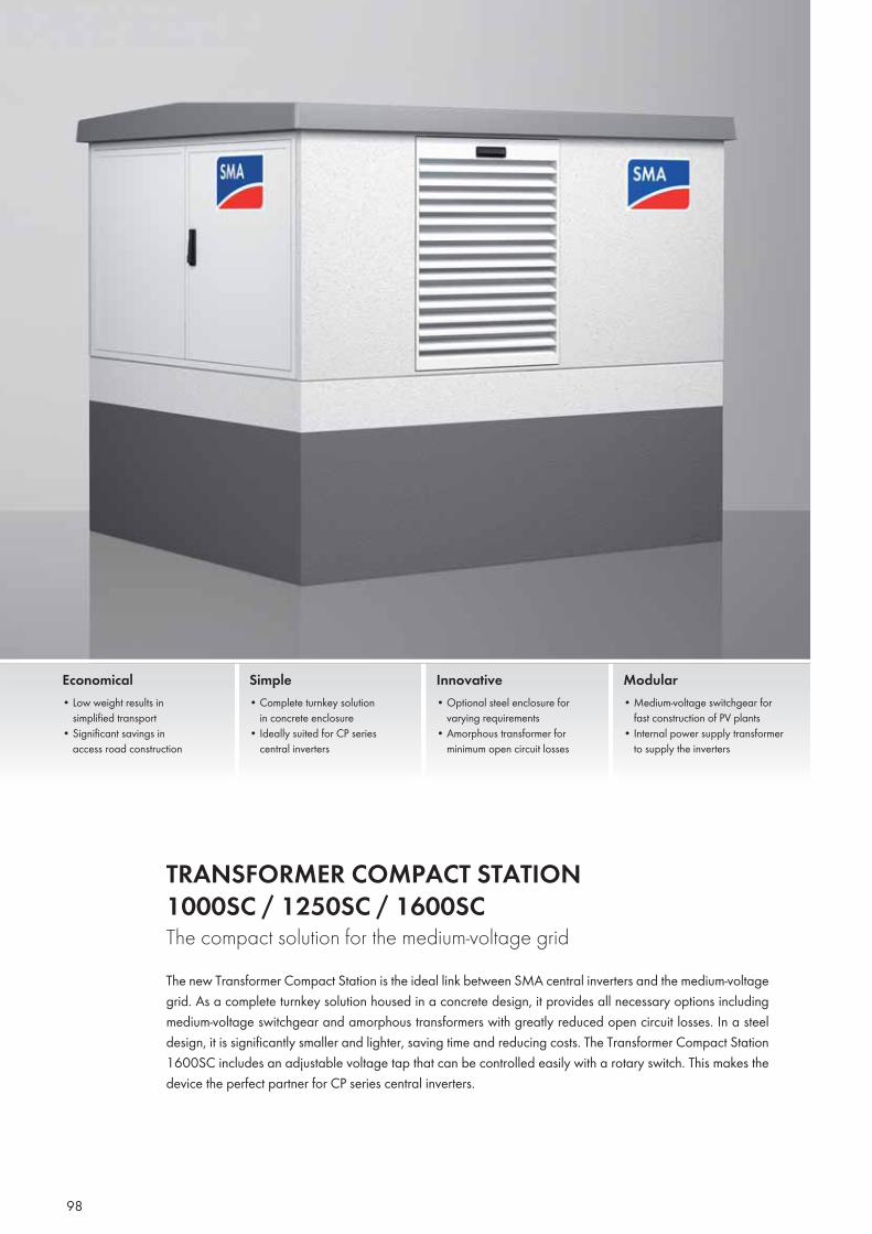
98
TRANSFORMER COMPACT STATION 1000SC / 1250SC / 1600SCThe compact solution for the medium-voltage gridThe new Transformer Compact Station is the ideal link between SMA central inverters and the medium-voltage grid. As a complete turnkey solution housed in a concrete design, it provides all necessary options including medium-voltage switchgear and amorphous transformers with greatly reduced open circuit losses. In a steel design, it is significantly smaller and lighter, saving time and reducing costs. The Transformer Compact Station 1600SC includes an adjustable voltage tap that can be controlled easily with a rotary switch. This makes the device the perfect partner for CP series central inverters.
Economical• Low weight results in simplified transport • Significant savings in access road construction
Simple• Complete turnkey solution in concrete enclosure• Ideally suited for CP series central inverters
Innovative• Optional steel enclosure for varying requirements• Amorphous transformer for minimum open circuit losses
Modular• Medium-voltage switchgear for fast construction of PV plants• Internal power supply transformer to supply the inverters
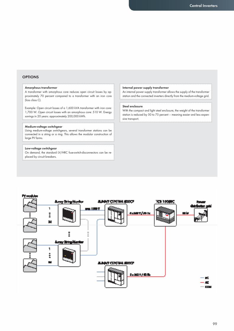
99
Central Inverters
Amorphous transformerA transformer with amorphous core reduces open circuit losses by ap-proximately 70 percent compared to a transformer with an iron core (loss class C).
Example: Open circuit losses of a 1,600 kVA transformer with iron core: 1,700 W. Open circuit losses with an amorphous core: 510 W. Energy savings in 20 years: approximately 200,000 kWh.
Medium-voltage switchgearUsing medium-voltage switchgears, several transformer stations can be connected in a string or a ring. This allows the modular construction of large PV farms.
Low-voltage switchgearOn demand, the standard LV/HRC fuse-switch-disconnectors can be re-placed by circuit breakers.
Internal power supply transformerAn internal power supply transformer allows the supply of the transformer station and the connected inverters directly from the medium-voltage grid.
Steel enclosureWith the compact and light steel enclosure, the weight of the transformer station is reduced by 50 to 75 percent – meaning easier and less expen-sive transport.
OPTIONS
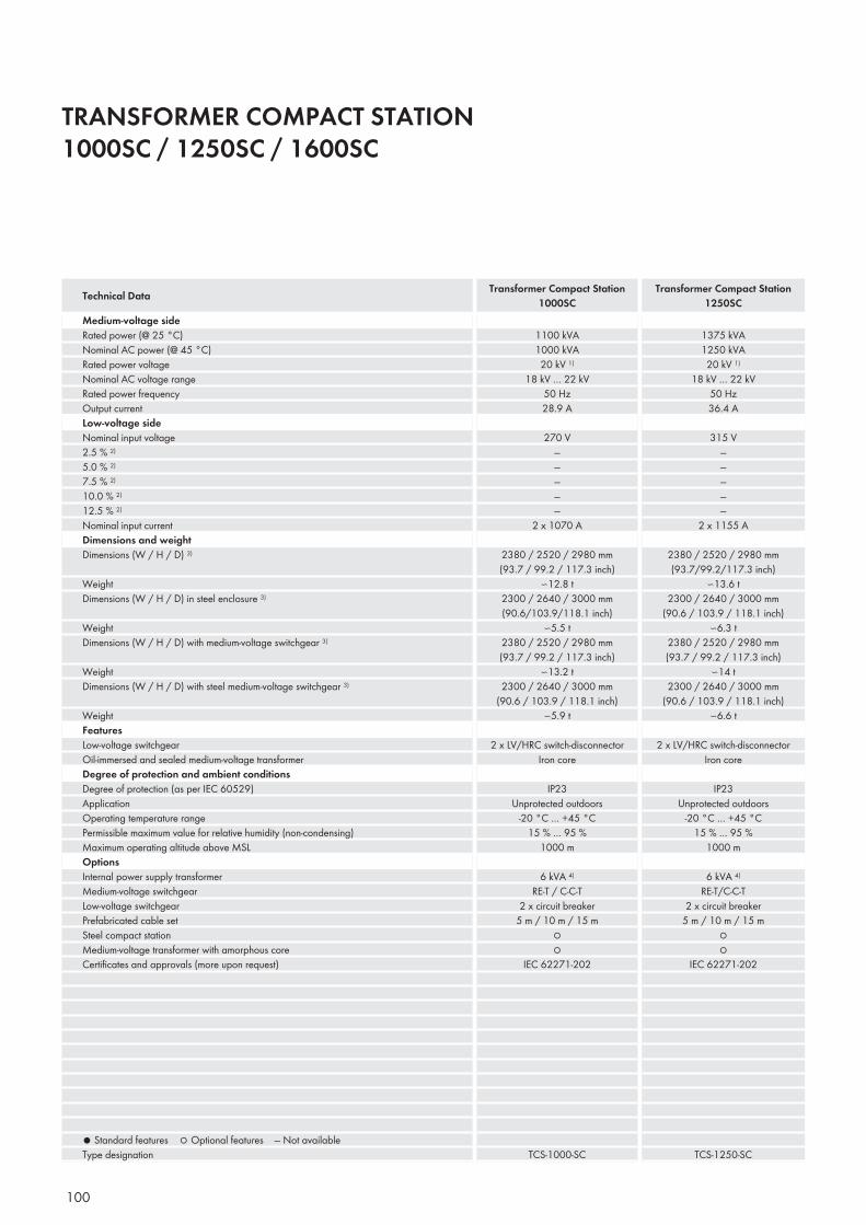
100
TRANSFORMER COMPACT STATION 1000SC / 1250SC / 1600SC
Medium-voltage sideRated power (@ 25 °C)Nominal AC power (@ 45 °C)Rated power voltageNominal AC voltage rangeRated power frequencyOutput currentLow-voltage sideNominal input voltage2.5 % 2)
5.0 % 2)
7.5 % 2)
10.0 % 2)
12.5 % 2)
Nominal input currentDimensions and weightDimensions (W / H / D) 3)
Weight Dimensions (W / H / D) in steel enclosure 3)
WeightDimensions (W / H / D) with medium-voltage switchgear 3)
WeightDimensions (W / H / D) with steel medium-voltage switchgear 3)
WeightFeaturesLow-voltage switchgear Oil-immersed and sealed medium-voltage transformerDegree of protection and ambient conditionsDegree of protection (as per IEC 60529)ApplicationOperating temperature rangePermissible maximum value for relative humidity (non-condensing)Maximum operating altitude above MSLOptionsInternal power supply transformerMedium-voltage switchgearLow-voltage switchgearPrefabricated cable setSteel compact stationMedium-voltage transformer with amorphous coreCertifi cates and approvals (more upon request)
● Standard features ○ Optional features — Not availableType designation
1100 kVA1000 kVA20 kV 1)
18 kV … 22 kV50 Hz28.9 A
270 V—————
2 x 1070 A
2380 / 2520 / 2980 mm(93.7 / 99.2 / 117.3 inch)
∽12.8 t2300 / 2640 / 3000 mm(90.6/103.9/118.1 inch)
∽5.5 t2380 / 2520 / 2980 mm(93.7 / 99.2 / 117.3 inch)
∽13.2 t2300 / 2640 / 3000 mm
(90.6 / 103.9 / 118.1 inch)∽5.9 t
2 x LV/HRC switch-disconnectorIron core
IP23Unprotected outdoors
-20 °C … +45 °C15 % … 95 %
1000 m
6 kVA 4)
RE-T / C-C-T2 x circuit breaker
5 m / 10 m / 15 m○○
IEC 62271-202
TCS-1000-SC
1375 kVA1250 kVA20 kV 1)
18 kV … 22 kV50 Hz36.4 A
315 V—————
2 x 1155 A
2380 / 2520 / 2980 mm(93.7/99.2/117.3 inch)
∽13.6 t2300 / 2640 / 3000 mm
(90.6 / 103.9 / 118.1 inch)∽6.3 t
2380 / 2520 / 2980 mm(93.7 / 99.2 / 117.3 inch)
∽14 t2300 / 2640 / 3000 mm
(90.6 / 103.9 / 118.1 inch)∽6.6 t
2 x LV/HRC switch-disconnectorIron core
IP23Unprotected outdoors
-20 °C … +45 °C15 % … 95 %
1000 m
6 kVA 4)
RE-T/C-C-T2 x circuit breaker
5 m / 10 m / 15 m○○
IEC 62271-202
TCS-1250-SC
Technical Data Transformer Compact Station1000SC
Transformer Compact Station1250SC
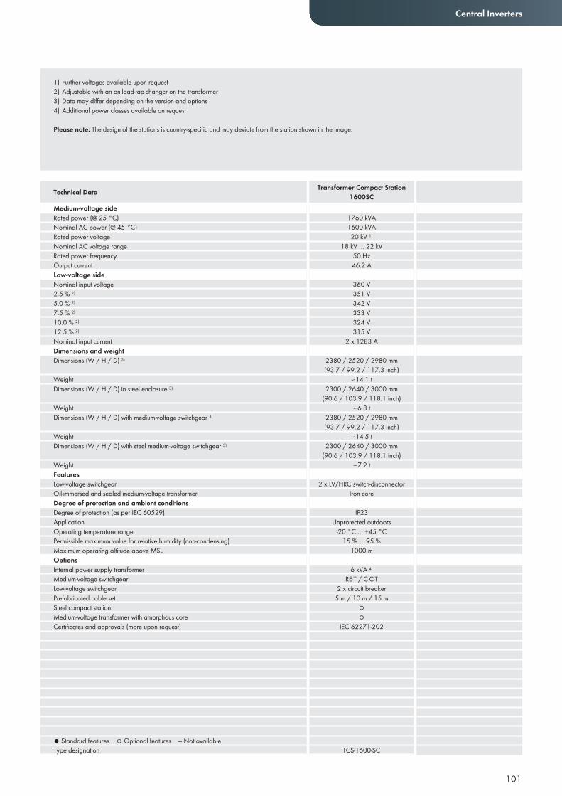
101
Central Inverters
Medium-voltage sideRated power (@ 25 °C)Nominal AC power (@ 45 °C)Rated power voltageNominal AC voltage rangeRated power frequencyOutput currentLow-voltage sideNominal input voltage2.5 % 2)
5.0 % 2)
7.5 % 2)
10.0 % 2)
12.5 % 2)
Nominal input currentDimensions and weightDimensions (W / H / D) 3)
Weight Dimensions (W / H / D) in steel enclosure 3)
WeightDimensions (W / H / D) with medium-voltage switchgear 3)
WeightDimensions (W / H / D) with steel medium-voltage switchgear 3)
WeightFeaturesLow-voltage switchgear Oil-immersed and sealed medium-voltage transformerDegree of protection and ambient conditionsDegree of protection (as per IEC 60529)ApplicationOperating temperature rangePermissible maximum value for relative humidity (non-condensing)Maximum operating altitude above MSLOptionsInternal power supply transformerMedium-voltage switchgearLow-voltage switchgearPrefabricated cable setSteel compact stationMedium-voltage transformer with amorphous coreCertifi cates and approvals (more upon request)
● Standard features ○ Optional features — Not availableType designation
1760 kVA1600 kVA20 kV 1)
18 kV … 22 kV50 Hz46.2 A
360 V351 V342 V333 V324 V315 V
2 x 1283 A
2380 / 2520 / 2980 mm(93.7 / 99.2 / 117.3 inch)
∽14.1 t2300 / 2640 / 3000 mm
(90.6 / 103.9 / 118.1 inch)∽6.8 t
2380 / 2520 / 2980 mm(93.7 / 99.2 / 117.3 inch)
∽14.5 t2300 / 2640 / 3000 mm
(90.6 / 103.9 / 118.1 inch)∽7.2 t
2 x LV/HRC switch-disconnectorIron core
IP23Unprotected outdoors
-20 °C … +45 °C15 % … 95 %
1000 m
6 kVA 4)
RE-T / C-C-T2 x circuit breaker
5 m / 10 m / 15 m○○
IEC 62271-202
TCS-1600-SC
Technical Data Transformer Compact Station1600SC
1) Further voltages available upon request2) Adjustable with an on-load-tap-changer on the transformer3) Data may differ depending on the version and options4) Additional power classes available on request
Please note: The design of the stations is country-specific and may deviate from the station shown in the image.
Transformer Compact Station1600SC

102
TRANSFORMER COMPACT STATION500SC / 630SC / 800SCThe compact solution for the medium-voltage gridThe new Transformer Compact Station is the ideal link between SMA central inverters and the medium-voltage grid. As a complete turnkey solution housed in a concrete design, it provides all necessary options including medium-voltage switchgear and amorphous transformers with greatly reduced open circuit losses. In a steel design, it is significantly smaller and lighter, saving time and reducing costs. The Transformer Compact Station 800SC includes an adjustable voltage tap that can be controlled easily with a rotary switch. This makes the device the perfect partner for CP series central inverters.
Economical• Low weight results in simplified transport • Significant savings in access road construction
Simple• Complete turnkey solution in concrete enclosure• Ideally suited for CP series central inverters
Innovative• Optional steel enclosure for varying requirements• Amorphous transformer for minimum open circuit losses
Modular• Medium-voltage switchgear for fast construction of PV plants• Internal power supply transformer to supply the inverters
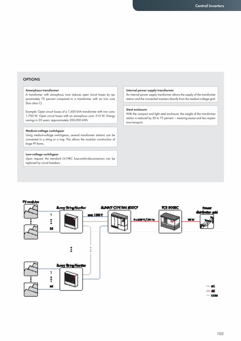
103
Central Inverters
Amorphous transformerA transformer with amorphous core reduces open circuit losses by ap-proximately 70 percent compared to a transformer with an iron core (loss class C).
Example: Open circuit losses of a 1,600 kVA transformer with iron core: 1,700 W. Open circuit losses with an amorphous core: 510 W. Energy savings in 20 years: approximately 200,000 kWh.
Medium-voltage switchgearUsing medium-voltage switchgears, several transformer stations can be connected in a string or a ring. This allows the modular construction of large PV farms.
Low-voltage switchgearUpon request, the standard LV/HRC fuse-switch-disconnectors can be replaced by circuit breakers.
Internal power supply transformerAn internal power supply transformer allows the supply of the transformer station and the connected inverters directly from the medium-voltage grid.
Steel enclosureWith the compact and light steel enclosure, the weight of the transformer station is reduced by 50 to 75 percent – meaning easier and less expen-sive transport.
OPTIONS
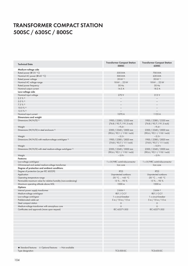
104
TRANSFORMER COMPACT STATION500SC / 630SC / 800SC
Medium-voltage sideRated power (@ 25 °C)Nominal AC power (@ 45 °C)Rated power voltageNominal AC voltage rangeRated power frequencyNominal output currentLow-voltage sideNominal input voltage2.5 % 2)
5.0 % 2)
7.5 % 2)
10.0 % 2)
12.5 % 2)
Nominal input currentDimensions and weightDimensions (W/H/D) 3)
Weight Dimensions (W/H/D) in steel enclosure 3)
WeightDimensions (W/H/D) with medium-voltage switchgear 3)
WeightDimensions (W/H/D) with steel medium-voltage switchgear 3)
WeightFeaturesLow-voltage switchgear Oil-immersed and sealed medium-voltage transformerDegree of protection and ambient conditionsDegree of protection (as per IEC 60529)ApplicationOperating temperature rangePermissible maximum value for relative humidity (non-condensing)Maximum operating altitude above MSLOptionsInternal power supply transformerMedium-voltage switchgearLow-voltage switchgearPrefabricated cable setSteel compact stationMedium-voltage transformer with amorphous coreCertifi cates and approvals (more upon request)
● Standard features ○ Optional features — Not availableType designation
550 kVA500 kVA20 kV 1)
18 kV … 22 kV50 Hz14.5 A
270 V—————
1070 A
1900 / 2380 / 2320 mm(74.8 / 93.7 / 91.3 inch)
∽9.4 t2300 / 2340 / 3000 mm(90.6 / 92.1 / 118.1 inch)
∽3.5 t1900 / 2380 / 2820 mm(74.8 / 93.7 / 111 inch)
∽10.9 t2300 / 2340 / 3000 mm(90.6 / 92.1 / 118.1 inch)
∽3.9 t
1 x LV/HRC switch-disconnectorIron core
IP23Unprotected outdoors
-20 °C … +45 °C15 % … 95 %
1000 m
3 kVA 4)
RE-T / C-C-T1 x circuit breaker
5 m / 10 m / 15 m○○
IEC 62271-202
TCS-500-SC
700 kVA630 kVA20 kV 1)
18 kV … 22 kV50 Hz18.2 A
315 V—————
1155 A
1900 / 2380 / 2320 mm(74.8 / 93.7 / 91.3 inch)
∽9.4 t2300 / 2340 / 3000 mm(90.6 / 92.1 / 118.1 inch)
∽3.5 t1900 / 2380 / 2820 mm(74.8 / 93.7 / 111 inch)
∽10.9 t2300 / 2340 / 3000 mm(90.6 / 92.1 / 118.1 inch)
∽3.9 t
1 x LV/HRC switch-disconnectorIron core
IP23Unprotected outdoors
-20 °C … +45 °C15 % … 95 %
1000 m
3 kVA 4)
RE-T / C-C-T1 x circuit breaker
5 m / 10 m / 15 m○○
IEC 62271-202
TCS-630-SC
Technical Data Transformer Compact Station500SC
Transformer Compact Station630SC
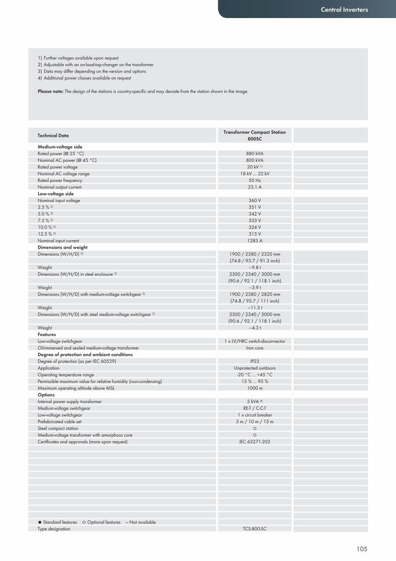
105
Central Inverters
Medium-voltage sideRated power (@ 25 °C)Nominal AC power (@ 45 °C)Rated power voltageNominal AC voltage rangeRated power frequencyNominal output currentLow-voltage sideNominal input voltage2.5 % 2)
5.0 % 2)
7.5 % 2)
10.0 % 2)
12.5 % 2)
Nominal input currentDimensions and weightDimensions (W/H/D) 3)
Weight Dimensions (W/H/D) in steel enclosure 3)
WeightDimensions (W/H/D) with medium-voltage switchgear 3)
WeightDimensions (W/H/D) with steel medium-voltage switchgear 3)
WeightFeaturesLow-voltage switchgear Oil-immersed and sealed medium-voltage transformerDegree of protection and ambient conditionsDegree of protection (as per IEC 60529)ApplicationOperating temperature rangePermissible maximum value for relative humidity (non-condensing)Maximum operating altitude above MSLOptionsInternal power supply transformerMedium-voltage switchgearLow-voltage switchgearPrefabricated cable setSteel compact stationMedium-voltage transformer with amorphous coreCertifi cates and approvals (more upon request)
● Standard features ○ Optional features — Not availableType designation
880 kVA800 kVA20 kV 1)
18 kV … 22 kV50 Hz23.1 A
360 V351 V342 V333 V324 V315 V
1283 A
1900 / 2380 / 2320 mm(74.8 / 93.7 / 91.3 inch)
∽9.8 t2300 / 2340 / 3000 mm(90.6 / 92.1 / 118.1 inch)
∽3.9 t1900 / 2380 / 2820 mm(74.8 / 93.7 / 111 inch)
∽11.3 t2300 / 2340 / 3000 mm(90.6 / 92.1 / 118.1 inch)
∽4.3 t
1 x LV/HRC switch-disconnectorIron core
IP23Unprotected outdoors
-20 °C … +45 °C15 % … 95 %
1000 m
3 kVA 4)
RE-T / C-C-T1 x circuit breaker
5 m / 10 m / 15 m○○
IEC 62271-202
TCS-800-SC
Technical Data Transformer Compact Station800SC
1) Further voltages available upon request2) Adjustable with an on-load-tap-changer on the transformer3) Data may differ depending on the version and options4) Additional power classes available on request
Please note: The design of the stations is country-specific and may deviate from the station shown in the image.
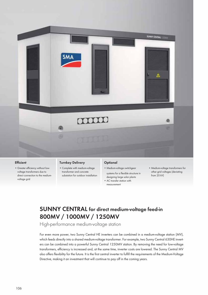
106
SUNNY CENTRAL for direct medium-voltage feed-in800MV / 1000MV / 1250MV High-performance medium-voltage stationFor even more power, two Sunny Central HE inverters can be combined in a medium-voltage station (MV), which feeds directly into a shared medium-voltage transformer. For example, two Sunny Central 630HE invert-ers can be combined into a powerful Sunny Central 1250MV station. By removing the need for low-voltage transformers, efficiency is increased and, at the same time, inverter costs are lowered. The Sunny Central MV also offers flexibility for the future. It is the first central inverter to fulfill the requirements of the Medium-Voltage Directive, making it an investment that will continue to pay off in the coming years.
Efficient• Greater efficiency without low-
voltage transformers due to direct connection to the medium-voltage grid
Turnkey Delivery• Complete with medium-voltage
transformer and concrete substation for outdoor installation
Optional• Medium-voltage switchgear
systems for a flexible structure in designing large solar plants
• AC transfer station with measurement
• Medium-voltage transformers for other grid voltages (deviating from 20 kV)
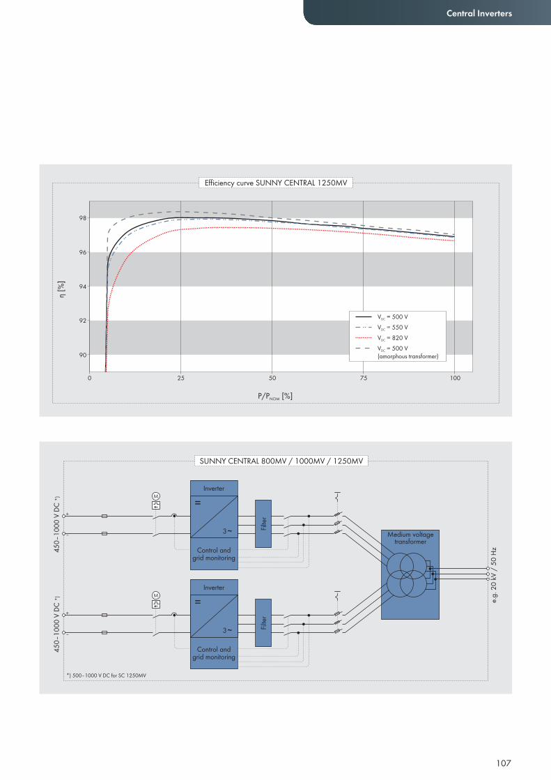
107
Central Inverters
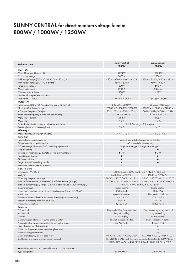
108
SUNNY CENTRAL for direct medium-voltage feed-in800MV / 1000MV / 1250MV
Input (DC)Max. DC power (@ cos ϕ=1)Max. input voltage MPP voltage range (@ 25 °C / @ 45 °C at 50 Hz) 1)
MPP voltage range (@ 25 °C at 60 Hz) 1)
Rated input voltageMax. input currentMinimum input voltageNumber of independent MPP inputsNumber of DC inputsOutput (AC)Rated power (@ 25 °C) / nominal AC power (@ 45 °C) Nominal AC voltage / rangeAC power frequency / rangeRated power frequency / rated power frequencyMax. output currentMax. THDPower factor at rated power / adjustable shift factorFeed-in phases / connection phasesEffi ciency 2)
Max. effi ciency / European effi ciencyProtectionInput side disconnection deviceOutput side disconnection deviceDC overvoltage protection / AC overvoltage protectionGrid monitoringGround fault monitoring / Remote ground fault monitoringInsulation monitoringGalvanic isolationSurge arrester for auxiliary supplyProtection class (as per IEC 62103)General DataDimensions (W / H / D)WeightOperating temperature rangeMax. self-consumption (in operation) / self-consumption (at night)External auxiliary supply voltage / External back-up fuse for auxiliary supplyCooling conceptDegree of protection: electronics / connection area (as per IEC 60529)ApplicationMaximum permissible value for relative humidity (non-condensing)Maximum operating altitude above MSLFresh air consumptionFeaturesDC terminalAC terminalDisplayCommunication interfaces / Sunny String-MonitorAnalog inputs / overvoltage protection for analog inputsInternal power supply transformerMedium-voltage transformer with amorphous coreMedium-voltage switchgearColor of enclosure / door / base / roofCertifi cates and approvals (more upon request)
● Standard features ○ Optional features — Not availableType designation
909 kW1000 V
450 V – 820 V / 450 V – 820 V450 V – 820 V
500 V1986 A450 V
2(16+16) + 4 DCHV
880 kVA / 800 kVA20000 V / 18000 V – 22000 V50 Hz, 60 Hz / 47 Hz … 63 Hz
50 Hz / 20000 V25.4 A< 3 %
1133 kW1000 V
450 V – 820 V / 450 V – 820 V450 V – 820 V
500 V2484 A450 V
2(16+16) + 4 DCHV
1100 kVA / 1000 kVA20000 V / 18000 V – 22000 V50 Hz, 60 Hz / 47 Hz … 63 Hz
50 Hz / 20000 V31.8 A< 3 %
Technical Data Sunny Central800MV
Sunny Central1000MV
1 / 0.9 leading ... 0.9 lagging3 / 3 3 / 3
Motor-driven switch-disconnector on DC sideAC fuse-switch-disconnector
Surge arrester type II / surge arrester type I
97.7 % / 97.3 %
●● / ○
●●●I
5400 / 3620 / 3000 mm (212.6 / 142.5 / 118.1 inch)35000 kg / 77162 lb
-20 °C … +45 °C / -4 °F … +113 °F3000 W 3) / < 180 W + 1100 W 5)
1000 m12400 m³/h
Ring terminal lug / cage terminalRing terminal lugLC text display
Ethernet, modbus / RS4854 x Ain 4) / ○
○○○
RAL 7035 / 7024 / 7024 / 7024EN 61000-6-2, EN 61000-6-4, EMC conformity, CE conformity, BDEW-MSRL /
FGW / TR8⁶⁾, Arrêté du 4/23/08, R.D. 1663 / 2000, R.D. 661 / 2007
SC 800MV-11
●● / ○
●●●I
97.9 % / 97.5 %
35000 kg / 77162 lb-20 °C … +45 °C / -4 °F … +113 °F3000 W 3) / < 180 W + 1100 W 5)
1000 m12400 m³/h
Ring terminal lug / cage terminalRing terminal lugLC text display
Ethernet, modbus / RS4854 x Ain 4) / ○
○○○
RAL 7035 / 7024 / 7024 / 7024
SC 1000MV-11
Forced coolingIP20 / IP54
Unprotected outdoors15 % … 95 %
3 x 230 V, 50 / 60 Hz / B 20 A, 3-poleForced cooling
IP20 / IP54Unprotected outdoors
15 % … 95 %

109
Central Inverters
1448 kW1000 V
500 V – 820 V / 500 V – 820 V510 V – 820 V
550 V2844 A500 V
2(16+16) + 4 DCHV
1400 kVA / 1250 kVA20000 V / 18000 V – 22000 V50 Hz, 60 Hz / 47 Hz … 63 Hz
50 Hz / 20000 V40.4 A< 3 %
HE: High Efficiency, inverter without galvanic isolation for connection to a medium-voltage transformer (taking into account the SMA specification for the transformer)1) At 1.05 VAC, nom and cos ϕ = 1 2) Efficiency measured without an internal power supply at VDC = 500 V3) Maximum power in one phase for each inverter < 1400 W (asymmetrical consumption)4) Each with 1x irradiation sensor and 1x pyranometer5) Disconnected according to the transformer's open circuit losses and inverter consumption6) With limited dynamic grid support
Please note: In certain countries the stations may differ from the concept shown in the images.
Input (DC)Max. DC power (@ cos ϕ=1)Max. input voltage MPP voltage range (@ 25 °C / @ 45 °C at 50 Hz) 1)
MPP voltage range (@ 25 °C at 60 Hz) 1)
Rated input voltageMax. input currentMinimum input voltageNumber of independent MPP inputsNumber of DC inputsOutput (AC)Rated power (@ 25 °C) / nominal AC power (@ 45 °C) Nominal AC voltage / rangeAC power frequency / rangeRated power frequency / rated power frequencyMax. output currentMax. THDPower factor at rated power / adjustable shift factorFeed-in phases / connection phasesEffi ciency 2)
Max. effi ciency / European effi ciencyProtectionInput side disconnection deviceOutput side disconnection deviceDC overvoltage protection / AC overvoltage protectionGrid monitoringGround fault monitoring / Remote ground fault monitoringInsulation monitoringGalvanic isolationSurge arrester for auxiliary supplyProtection class (as per IEC 62103)General DataDimensions (W / H / D)WeightOperating temperature rangeMax. self-consumption (in operation) / self-consumption (at night)External auxiliary supply voltage / External back-up fuse for auxiliary supplyCooling conceptDegree of protection: electronics / connection area (as per IEC 60529)ApplicationMaximum permissible value for relative humidity (non-condensing)Maximum operating altitude above MSLFresh air consumptionFeaturesDC terminalAC terminalDisplayCommunication interfaces / Sunny String-MonitorAnalog inputs / overvoltage protection for analog inputsInternal power supply transformerMedium-voltage transformer with amorphous coreMedium-voltage switchgearColor of enclosure / door / base / roofCertifi cates and approvals (more upon request)
● Standard features ○ Optional features — Not availableType designation
Technical Data Sunny Central1250MV
1 / 0.9 leading ... 0.9 lagging3 / 3
Motor-driven switch disconnector on DC sideAC fuse-switch-disconnector
Surge arrester type II / surge arrester type I
97.8 % / 97.4 %
●● / ○
●●●I
5400 / 3620 / 3000 mm (212.6 / 142.5 / 118.1 inch)35000 kg / 77162 lb
-20 °C … +45 °C / -4 °F … +113 °F3000 W3) / < 180 W + 1350 W 5)
1000 m12400 m³/h
Ring terminal lug / cage terminalRing terminal lugLC text display
Ethernet, modbus / RS4854 x Ain 4) / ○
○○○
RAL 7035 / 7024 / 7024 / 7024EN 61000-6-2, EN 61000-6-4, EMC conformity, CE conformity, BDEW-MSRL /
FGW / TR8⁶⁾, Arrêté du 4/23/08, R.D. 1663 / 2000, R.D. 661 / 2007
SC 1250MV-11
Forced coolingIP20 / IP54
Unprotected outdoors15 % … 95 %
3 x 230 V, 50 / 60 Hz / B 20 A, 3-pole

110
SUNNY CENTRAL for direct medium-voltage feed-in 400MV / 500MV / 630MV The compact station for safe grid managementEquipped with a new SMA HE central inverter and a medium-voltage transformer, the Sunny Central MV feeds directly into the medium-voltage grid. By removing the need for low-voltage transformers, efficiency is increased and, at the same time, inverter costs are lowered. The Sunny Central MV is delivered as a “turnkey” concrete substation for outside installation. The Sunny Central MV also actively participates in grid management, fulfilling all requirements of the Medium-Voltage Directive.
Efficient• Greater efficiency without low
voltage transformers due to direct connection to the medium-voltage grid
Turnkey Delivery• Complete with medium-voltage
transformer and concrete substation for outdoor installation
Optional• Medium-voltage switchgear
systems for a flexible structure in designing large solar plants
• AC transfer station with measurement
• Medium-voltage transformers for other grid voltages (deviating from 20 kV)
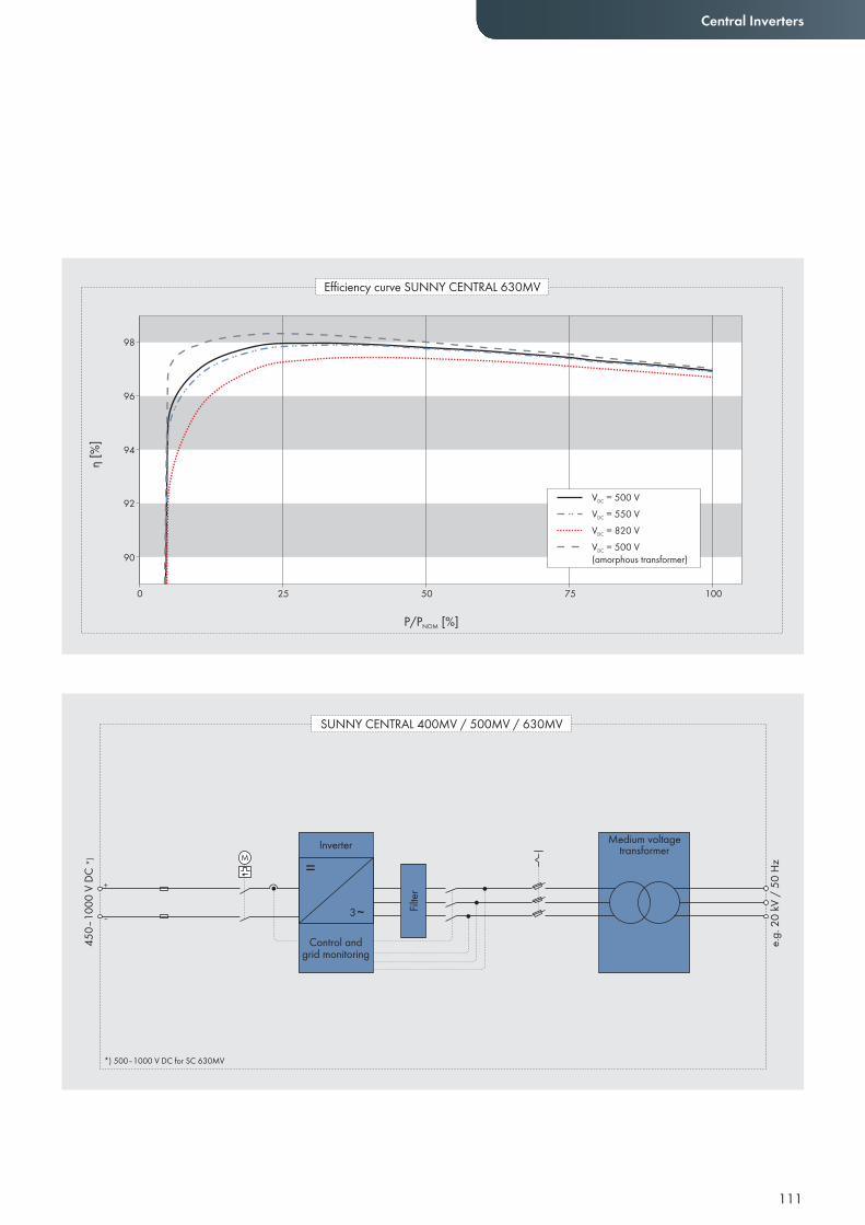
111
Central Inverters
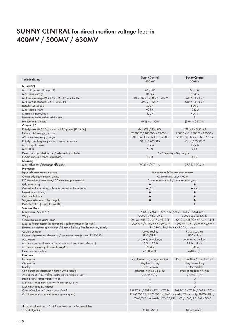
112
SUNNY CENTRAL for direct medium-voltage feed-in 400MV / 500MV / 630MV
Input (DC)Max. DC power (@ cos ϕ=1)Max. input voltage MPP voltage range (@ 25 °C / @ 45 °C at 50 Hz) 1)
MPP voltage range (@ 25 °C at 60 Hz) 1)
Rated input voltageMax. input currentMinimum input voltageNumber of independent MPP inputsNumber of DC inputsOutput (AC)Rated power (@ 25 °C) / nominal AC power (@ 45 °C) Nominal AC voltage / rangeAC power frequency / rangeRated power frequency / rated power frequencyMax. output currentMax. THDPower factor at rated power / adjustable shift factorFeed-in phases / connection phasesEffi ciency 2)
Max. effi ciency / European effi ciencyProtectionInput side disconnection deviceOutput side disconnection deviceDC overvoltage protection / AC overvoltage protectionGrid monitoringGround fault monitoring / Remote ground fault monitoringInsulation monitoringGalvanic isolationSurge arrester for auxiliary supplyProtection class (as per IEC 62103)General DataDimensions (W / H / D)WeightOperating temperature rangeMax. self-consumption (in operation) / self-consumption (at night)External auxiliary supply voltage / External back-up fuse for auxiliary supplyCooling conceptDegree of protection: electronics / connection area (as per IEC 60529)ApplicationMaximum permissible value for relative humidity (non-condensing)Maximum operating altitude above MSLFresh air consumptionFeaturesDC terminalAC terminalDisplayCommunication interfaces / Sunny String-MonitorAnalog inputs / overvoltage protection for analog inputsInternal power supply transformerMedium-voltage transformer with amorphous coreMedium-voltage switchgearColor of enclosure / door / base / roofCertifi cates and approvals (more upon request)
● Standard features ○ Optional features — Not availableType designation
Technical Data Sunny Central400MV
Sunny Central500MV
455 kW1000 V
450 V - 820 V / 450 V - 820 V450 V – 820 V
500 V993 A450 V
1(8+8) + 2 DCHV
440 kVA / 400 kVA20000 V / 18000 V – 22000 V50 Hz, 60 Hz / 47 Hz … 63 Hz
50 Hz / 20000 V12.7 A< 3 %
567 kW1000 V
450 V – 820 V 1)
450 V – 820 V 1)
500 V1242 A450 V
1(8+8) + 2 DCHV
550 kVA / 500 kVA20000 V / 18000 V – 22000 V50 Hz, 60 Hz / 47 Hz … 63 Hz
50 Hz / 20000 V15.9 A< 3 %
1 / 0.9 leading ... 0.9 lagging3 / 3 3 / 3
Motor-driven DC switch-disconnectorAC fuse-switch-disconnector
Surge arrester type II / surge arrester type I
97.5 % / 97.1 %
●● / ○
●●●I
5300 / 3600 / 2500 mm (208.7 / 141.7 / 98.4 inch)30000 kg / 66139 lb
-20 °C … +45 °C / -4 °F … +113 °F1500 W 3) / < 100 W + 720 W 5)
1000 m6200 m³/h
Ring terminal lug / cage terminalRing terminal lugLC text display
Ethernet, modbus / RS4852 x Ain 4) / ○
○○○
RAL 7035 / 7024 / 7024 / 7024EN 61000-6-2, EN 61000-6-4, EMC conformity, CE conformity, BDEW-MSRL /
FGW / TR8⁶⁾, Arrêté du 4/23/08, R.D. 1663 / 2000, R.D. 661 / 2007
SC 400MV-11
●● / ○
●●●I
97.7 % / 97.3 %
30000 kg / 66139 lb-20 °C … +45 °C / -4 °F … +113 °F1500 W 3) / < 100 W + 720 W 5)
1000 m6200 m³/h
Ring terminal lug / cage terminalRing terminal lugLC text display
Ethernet, modbus / RS4852 x Ain 4) / ○
○○○
RAL 7035 / 7024 / 7024 / 7024
SC 500MV-11
Forced coolingIP20 / IP54
Unprotected outdoors15 % … 95 %
3 x 230 V, 50 / 60 Hz / B 20 A, 3-poleForced cooling
IP20 / IP54Unprotected outdoors
15 % … 95 %
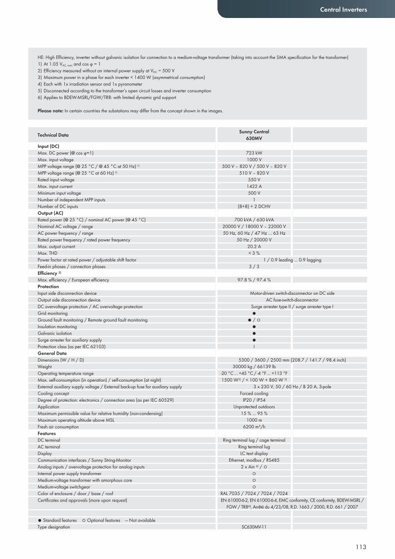
113
Central Inverters
HE: High Efficiency, inverter without galvanic isolation for connection to a medium-voltage transformer (taking into account the SMA specification for the transformer)1) At 1.05 VAC, nom and cos ϕ = 1 2) Efficiency measured without an internal power supply at VDC = 500 V3) Maximum power in a phase for each inverter < 1400 W (asymmetrical consumption)4) Each with 1x irradiation sensor and 1x pyranometer5) Disconnected according to the transformer’s open circuit losses and inverter consumption6) Applies to BDEW-MSRL/FGW/TR8: with limited dynamic grid support
Please note: In certain countries the substations may differ from the concept shown in the images.
Input (DC)Max. DC power (@ cos ϕ=1)Max. input voltage MPP voltage range (@ 25 °C / @ 45 °C at 50 Hz) 1)
MPP voltage range (@ 25 °C at 60 Hz) 1)
Rated input voltageMax. input currentMinimum input voltageNumber of independent MPP inputsNumber of DC inputsOutput (AC)Rated power (@ 25 °C) / nominal AC power (@ 45 °C) Nominal AC voltage / rangeAC power frequency / rangeRated power frequency / rated power frequencyMax. output currentMax. THDPower factor at rated power / adjustable shift factorFeed-in phases / connection phasesEffi ciency 2)
Max. effi ciency / European effi ciencyProtectionInput side disconnection deviceOutput side disconnection deviceDC overvoltage protection / AC overvoltage protectionGrid monitoringGround fault monitoring / Remote ground fault monitoringInsulation monitoringGalvanic isolationSurge arrester for auxiliary supplyProtection class (as per IEC 62103)General DataDimensions (W / H / D)WeightOperating temperature rangeMax. self-consumption (in operation) / self-consumption (at night)External auxiliary supply voltage / External back-up fuse for auxiliary supplyCooling conceptDegree of protection: electronics / connection area (as per IEC 60529)ApplicationMaximum permissible value for relative humidity (non-condensing)Maximum operating altitude above MSLFresh air consumptionFeaturesDC terminalAC terminalDisplayCommunication interfaces / Sunny String-MonitorAnalog inputs / overvoltage protection for analog inputsInternal power supply transformerMedium-voltage transformer with amorphous coreMedium-voltage switchgearColor of enclosure / door / base / roofCertifi cates and approvals (more upon request)
● Standard features ○ Optional features — Not availableType designation
Technical Data Sunny Central630MV
723 kW1000 V
500 V – 820 V / 500 V – 820 V510 V – 820 V
550 V1422 A500 V
1(8+8) + 2 DCHV
700 kVA / 630 kVA20000 V / 18000 V – 22000 V50 Hz, 60 Hz / 47 Hz … 63 Hz
50 Hz / 20000 V20.2 A< 3 %
1 / 0.9 leading ... 0.9 lagging3 / 3
Motor-driven switch-disconnector on DC sideAC fuse-switch-disconnector
Surge arrester type II / surge arrester type I
97.8 % / 97.4 %
●● / ○
●●●I
5300 / 3600 / 2500 mm (208.7 / 141.7 / 98.4 inch)30000 kg / 66139 lb
-20 °C … +45 °C / -4 °F … +113 °F1500 W3) / < 100 W + 860 W 5)
1000 m6200 m³/h
Ring terminal lug / cage terminalRing terminal lugLC text display
Ethernet, modbus / RS4852 x Ain 4) / ○
○○○
RAL 7035 / 7024 / 7024 / 7024EN 61000-6-2, EN 61000-6-4, EMC conformity, CE conformity, BDEW-MSRL /
FGW / TR8⁶⁾, Arrêté du 4/23/08, R.D. 1663 / 2000, R.D. 661 / 2007
SC630MV-11
Forced coolingIP20 / IP54
Unprotected outdoors15 % … 95 %
3 x 230 V, 50 / 60 Hz / B 20 A, 3-pole
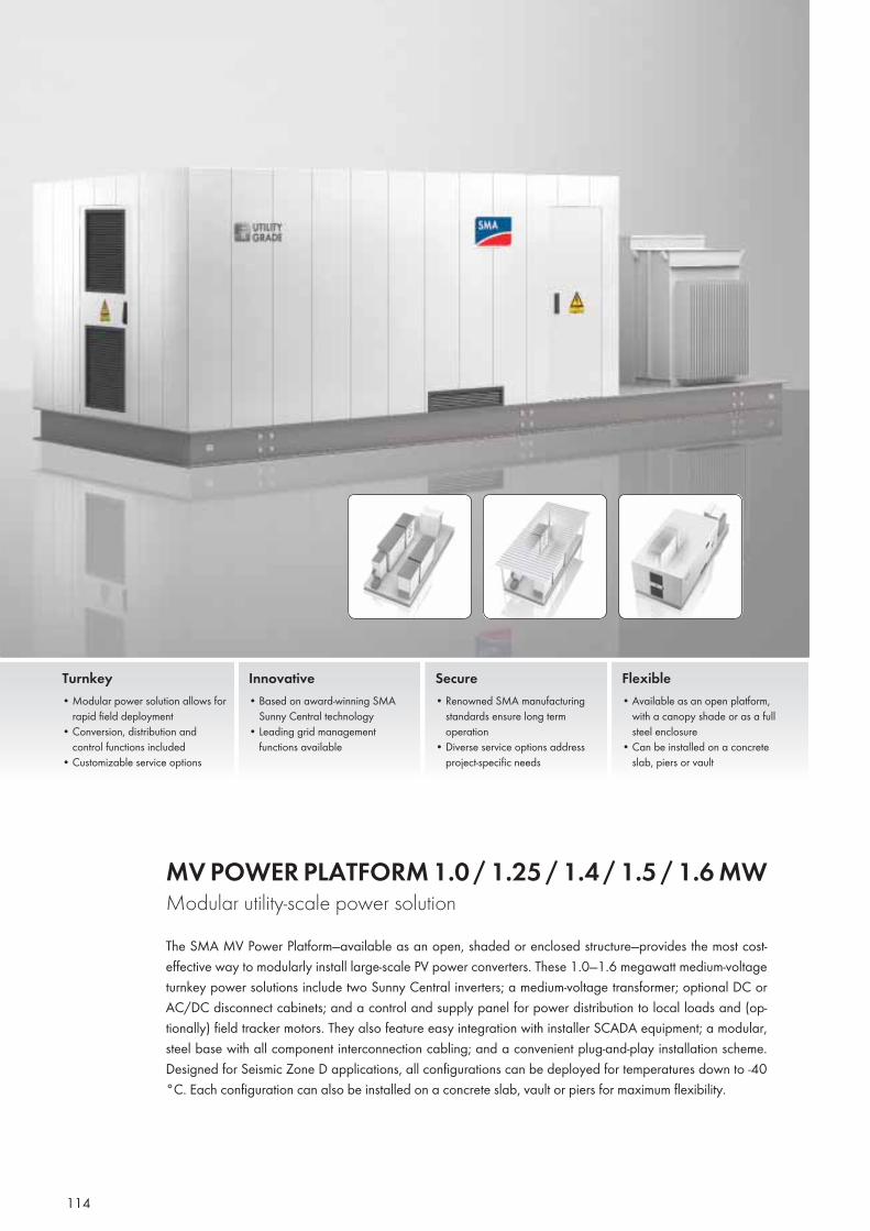
114
MV POWER PLATFORM 1.0 / 1.25 / 1.4 / 1.5 / 1.6 MW Modular utility-scale power solutionThe SMA MV Power Platform—available as an open, shaded or enclosed structure—provides the most cost-effective way to modularly install large-scale PV power converters. These 1.0—1.6 megawatt medium-voltage turnkey power solutions include two Sunny Central inverters; a medium-voltage transformer; optional DC or AC/DC disconnect cabinets; and a control and supply panel for power distribution to local loads and (op-tionally) field tracker motors. They also feature easy integration with installer SCADA equipment; a modular, steel base with all component interconnection cabling; and a convenient plug-and-play installation scheme. Designed for Seismic Zone D applications, all configurations can be deployed for temperatures down to -40 °C. Each configuration can also be installed on a concrete slab, vault or piers for maximum flexibility.
Turnkey• Modular power solution allows for
rapid fi eld deployment• Conversion, distribution and
control functions included• Customizable service options
Innovative• Based on award-winning SMA
Sunny Central technology• Leading grid management
functions available
Secure• Renowned SMA manufacturing
standards ensure long term operation
• Diverse service options address project-specific needs
Flexible• Available as an open platform,
with a canopy shade or as a full steel enclosure
• Can be installed on a concrete slab, piers or vault
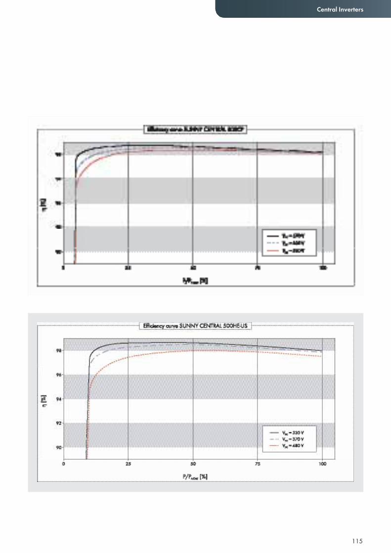
115
Central Inverters
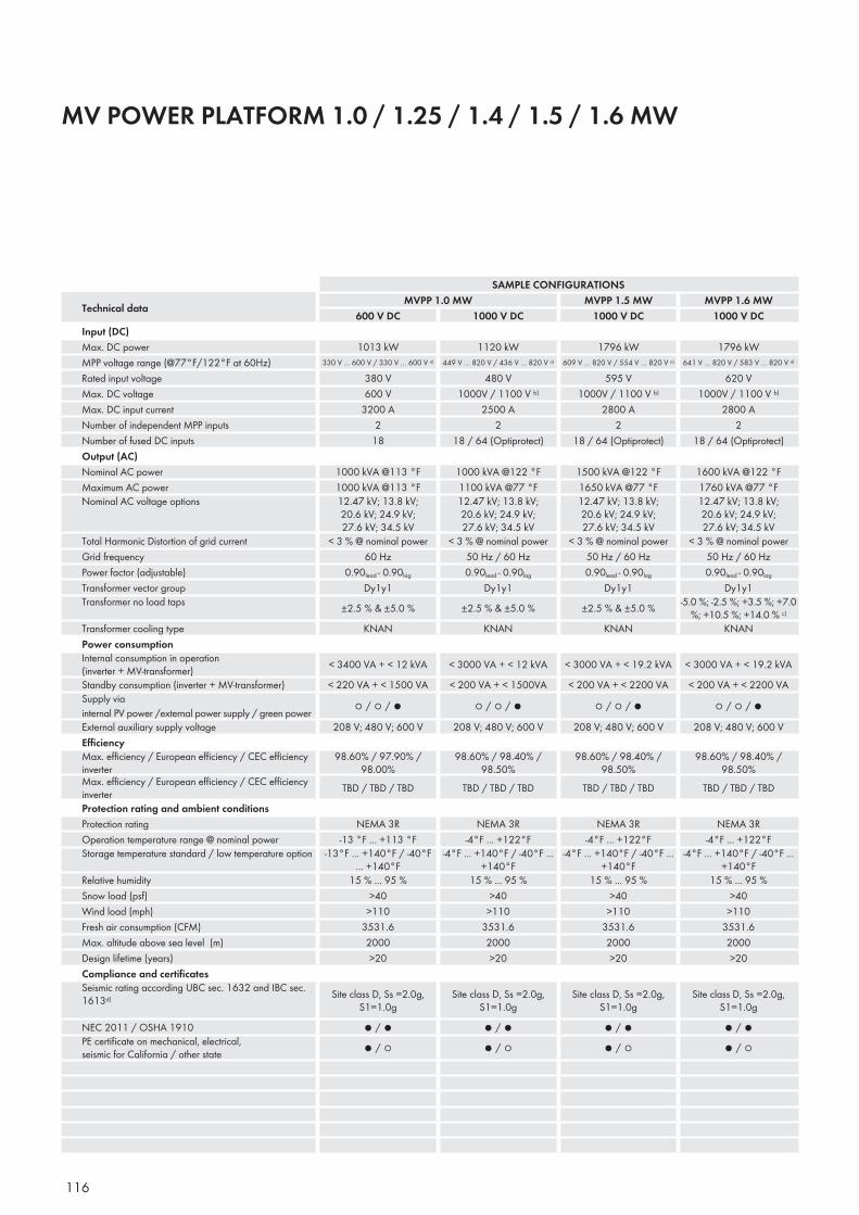
116
MV POWER PLATFORM 1.0 / 1.25 / 1.4 / 1.5 / 1.6 MW
SAMPLE CONFIGURATIONS
Technical data MVPP 1.0 MW MVPP 1.5 MW MVPP 1.6 MW 600 V DC 1000 V DC 1000 V DC 1000 V DC
Input (DC) Max. DC power 1013 kW 1120 kW 1796 kW 1796 kWMPP voltage range (@77°F/122°F at 60Hz) 330 V … 600 V / 330 V … 600 V a) 449 V … 820 V / 436 V … 820 V a) 609 V … 820 V / 554 V … 820 V a) 641 V … 820 V / 583 V … 820 V a)
Rated input voltage 380 V 480 V 595 V 620 VMax. DC voltage 600 V 1000V / 1100 V b) 1000V / 1100 V b) 1000V / 1100 V b)
Max. DC input current 3200 A 2500 A 2800 A 2800 ANumber of independent MPP inputs 2 2 2 2Number of fused DC inputs 18 18 / 64 (Optiprotect) 18 / 64 (Optiprotect) 18 / 64 (Optiprotect)Output (AC) Nominal AC power 1000 kVA @113 °F 1000 kVA @122 °F 1500 kVA @122 °F 1600 kVA @122 °FMaximum AC power 1000 kVA @113 °F 1100 kVA @77 °F 1650 kVA @77 °F 1760 kVA @77 °FNominal AC voltage options 12.47 kV; 13.8 kV;
20.6 kV; 24.9 kV; 27.6 kV; 34.5 kV
12.47 kV; 13.8 kV; 20.6 kV; 24.9 kV; 27.6 kV; 34.5 kV
12.47 kV; 13.8 kV; 20.6 kV; 24.9 kV; 27.6 kV; 34.5 kV
12.47 kV; 13.8 kV; 20.6 kV; 24.9 kV; 27.6 kV; 34.5 kV
Total Harmonic Distortion of grid current < 3 % @ nominal power < 3 % @ nominal power < 3 % @ nominal power < 3 % @ nominal powerGrid frequency 60 Hz 50 Hz / 60 Hz 50 Hz / 60 Hz 50 Hz / 60 HzPower factor (adjustable) 0.90lead - 0.90lag 0.90lead - 0.90lag 0.90lead - 0.90lag 0.90lead - 0.90lag
Transformer vector group Dy1y1 Dy1y1 Dy1y1 Dy1y1Transformer no load taps ±2.5 % & ±5.0 % ±2.5 % & ±5.0 % ±2.5 % & ±5.0 % -5.0 %; -2.5 %; +3.5 %; +7.0
%; +10.5 %; +14.0 % c)
Transformer cooling type KNAN KNAN KNAN KNANPower consumption Internal consumption in operation (inverter + MV-transformer) < 3400 VA + < 12 kVA < 3000 VA + < 12 kVA < 3000 VA + < 19.2 kVA < 3000 VA + < 19.2 kVAStandby consumption (inverter + MV-transformer) < 220 VA + < 1500 VA < 200 VA + < 1500VA < 200 VA + < 2200 VA < 200 VA + < 2200 VASupply via internal PV power /external power supply / green power ○ / ○ / ● ○ / ○ / ● ○ / ○ / ● ○ / ○ / ●External auxiliary supply voltage 208 V; 480 V; 600 V 208 V; 480 V; 600 V 208 V; 480 V; 600 V 208 V; 480 V; 600 VEffi ciency Max. effi ciency / European effi ciency / CEC effi ciency inverter
98.60% / 97.90% / 98.00%
98.60% / 98.40% / 98.50%
98.60% / 98.40% / 98.50%
98.60% / 98.40% / 98.50%
Max. effi ciency / European effi ciency / CEC effi ciency inverter TBD / TBD / TBD TBD / TBD / TBD TBD / TBD / TBD TBD / TBD / TBDProtection rating and ambient conditions Protection rating NEMA 3R NEMA 3R NEMA 3R NEMA 3ROperation temperature range @ nominal power -13 °F ... +113 °F -4°F ... +122°F -4°F ... +122°F -4°F ... +122°FStorage temperature standard / low temperature option -13°F ... +140°F / -40°F
... +140°F-4°F ... +140°F / -40°F ...
+140°F-4°F ... +140°F / -40°F ...
+140°F-4°F ... +140°F / -40°F ...
+140°FRelative humidity 15 % ... 95 % 15 % ... 95 % 15 % ... 95 % 15 % ... 95 %Snow load (psf) >40 >40 >40 >40Wind load (mph) >110 >110 >110 >110Fresh air consumption (CFM) 3531.6 3531.6 3531.6 3531.6Max. altitude above sea level (m) 2000 2000 2000 2000Design lifetime (years) >20 >20 >20 >20Compliance and certifi cates Seismic rating according UBC sec. 1632 and IBC sec. 1613d)
Site class D, Ss =2.0g, S1=1.0g
Site class D, Ss =2.0g, S1=1.0g
Site class D, Ss =2.0g, S1=1.0g
Site class D, Ss =2.0g, S1=1.0g
NEC 2011 / OSHA 1910 ● / ● ● / ● ● / ● ● / ●PE certifi cate on mechanical, electrical, seismic for California / other state ● / ○ ● / ○ ● / ○ ● / ○
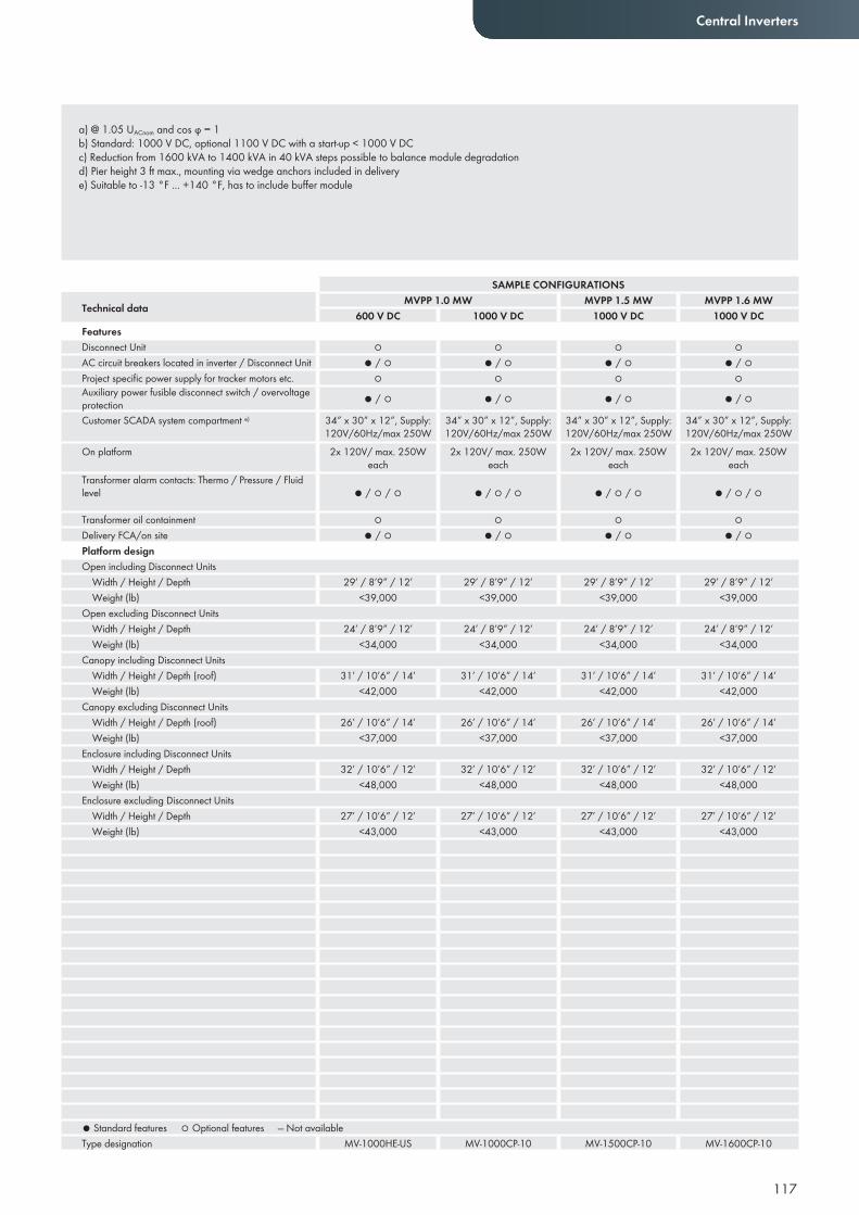
117
Central Inverters
a) @ 1.05 UACnom and cos ϕ = 1b) Standard: 1000 V DC, optional 1100 V DC with a start-up < 1000 V DCc) Reduction from 1600 kVA to 1400 kVA in 40 kVA steps possible to balance module degradationd) Pier height 3 ft max., mounting via wedge anchors included in delivery e) Suitable to -13 °F ... +140 °F, has to include buffer module
SAMPLE CONFIGURATIONS
Technical data MVPP 1.0 MW MVPP 1.5 MW MVPP 1.6 MW 600 V DC 1000 V DC 1000 V DC 1000 V DC
Features Disconnect Unit ○ ○ ○ ○AC circuit breakers located in inverter / Disconnect Unit ● / ○ ● / ○ ● / ○ ● / ○Project specifi c power supply for tracker motors etc. ○ ○ ○ ○Auxiliary power fusible disconnect switch / overvoltage protection ● / ○ ● / ○ ● / ○ ● / ○Customer SCADA system compartment e) 34” x 30” x 12”, Supply:
120V/60Hz/max 250W34” x 30” x 12”, Supply: 120V/60Hz/max 250W
34” x 30” x 12”, Supply: 120V/60Hz/max 250W
34” x 30” x 12”, Supply: 120V/60Hz/max 250W
On platform 2x 120V/ max. 250W each
2x 120V/ max. 250W each
2x 120V/ max. 250W each
2x 120V/ max. 250W each
Transformer alarm contacts: Thermo / Pressure / Fluid level ● / ○ / ○ ● / ○ / ○ ● / ○ / ○ ● / ○ / ○
Transformer oil containment ○ ○ ○ ○Delivery FCA/on site ● / ○ ● / ○ ● / ○ ● / ○Platform design Open including Disconnect Units
Width / Height / Depth 29’ / 8’9” / 12’ 29’ / 8’9” / 12’ 29’ / 8’9” / 12’ 29’ / 8’9” / 12’Weight (lb) <39,000 <39,000 <39,000 <39,000
Open excluding Disconnect Units Width / Height / Depth 24’ / 8’9” / 12’ 24’ / 8’9” / 12’ 24’ / 8’9” / 12’ 24’ / 8’9” / 12’Weight (lb) <34,000 <34,000 <34,000 <34,000
Canopy including Disconnect Units Width / Height / Depth (roof) 31’ / 10’6” / 14’ 31’ / 10’6” / 14’ 31’ / 10’6” / 14’ 31’ / 10’6” / 14’Weight (lb) <42,000 <42,000 <42,000 <42,000
Canopy excluding Disconnect Units Width / Height / Depth (roof) 26’ / 10’6” / 14’ 26’ / 10’6” / 14’ 26’ / 10’6” / 14’ 26’ / 10’6” / 14’Weight (lb) <37,000 <37,000 <37,000 <37,000
Enclosure including Disconnect Units Width / Height / Depth 32’ / 10’6” / 12’ 32’ / 10’6” / 12’ 32’ / 10’6” / 12’ 32’ / 10’6” / 12’Weight (lb) <48,000 <48,000 <48,000 <48,000
Enclosure excluding Disconnect Units Width / Height / Depth 27’ / 10’6” / 12’ 27’ / 10’6” / 12’ 27’ / 10’6” / 12’ 27’ / 10’6” / 12’Weight (lb) <43,000 <43,000 <43,000 <43,000
● Standard features ○ Optional features — Not availableType designation MV-1000HE-US MV-1000CP-10 MV-1500CP-10 MV-1600CP-10
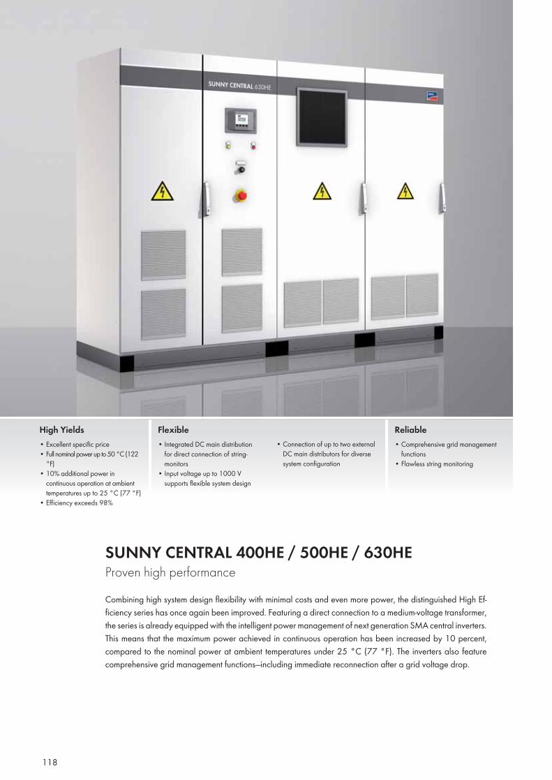
118
SUNNY CENTRAL 400HE / 500HE / 630HE Proven high performanceCombining high system design flexibility with minimal costs and even more power, the distinguished High Ef-ficiency series has once again been improved. Featuring a direct connection to a medium-voltage transformer, the series is already equipped with the intelligent power management of next generation SMA central inverters. This means that the maximum power achieved in continuous operation has been increased by 10 percent, compared to the nominal power at ambient temperatures under 25 °C (77 °F). The inverters also feature comprehensive grid management functions—including immediate reconnection after a grid voltage drop.
High Yields• Excellent specific price• Full nominal power up to 50 °C (122
°F)• 10% additional power in
continuous operation at ambient temperatures up to 25 °C (77 °F)
• Efficiency exceeds 98%
Flexible• Integrated DC main distribution
for direct connection of string-monitors
• Input voltage up to 1000 V supports flexible system design
• Connection of up to two external DC main distributors for diverse system configuration
Reliable• Comprehensive grid management
functions• Flawless string monitoring
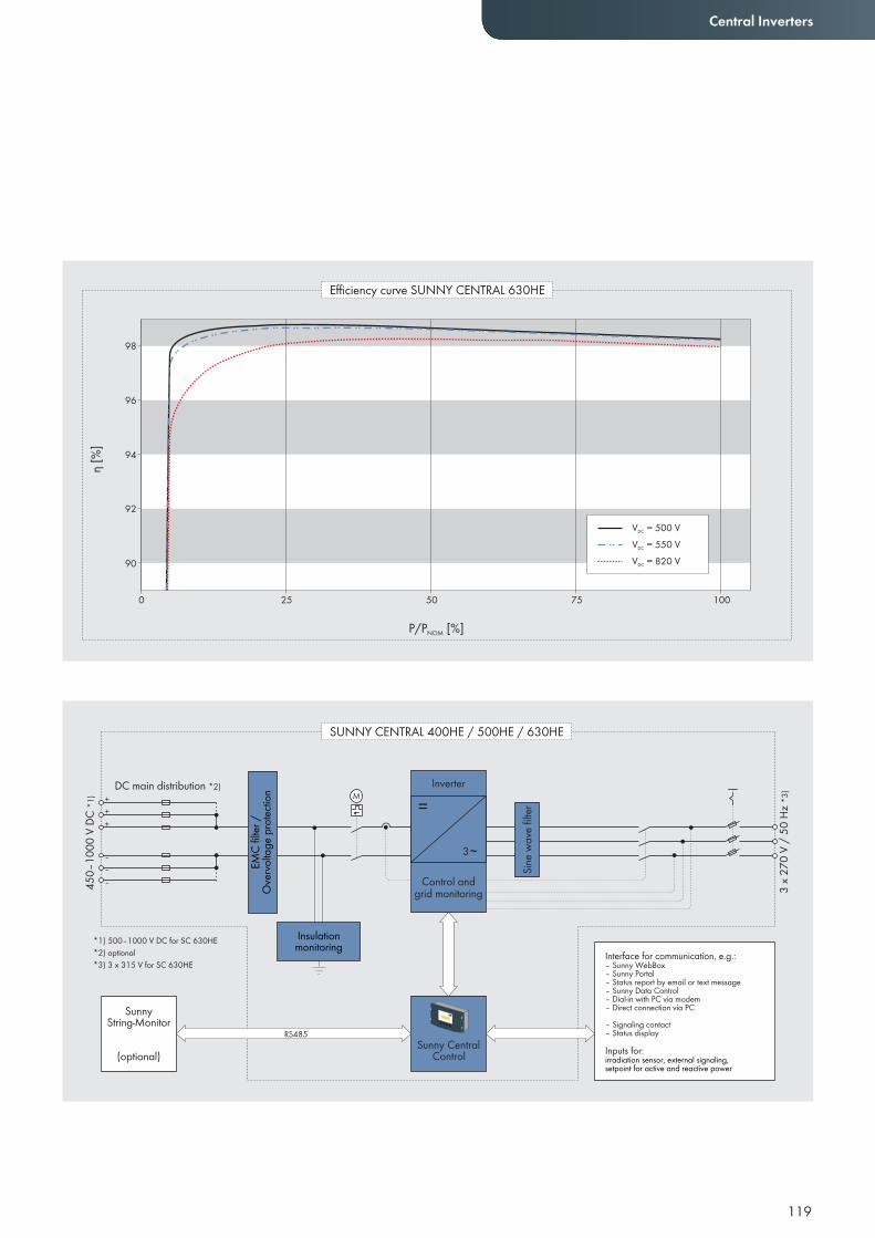
119
Central Inverters
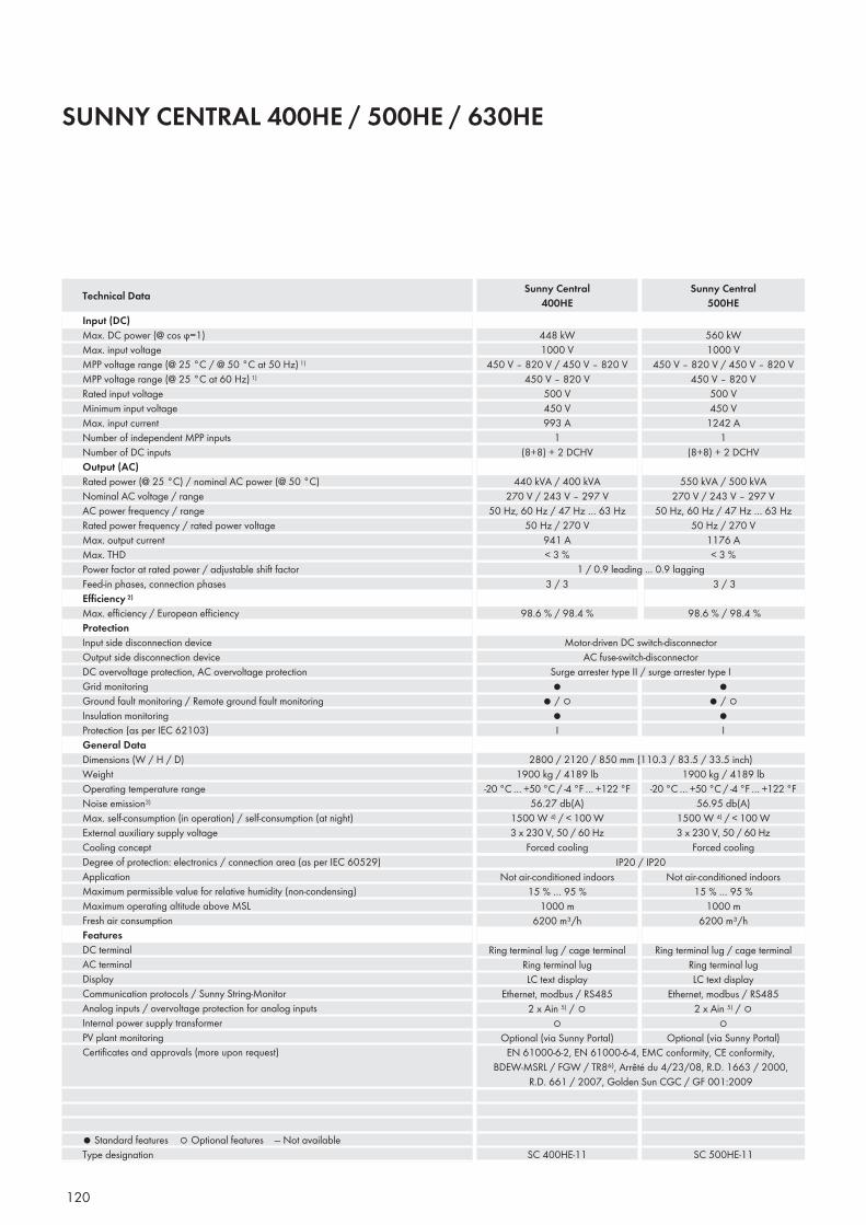
120
SUNNY CENTRAL 400HE / 500HE / 630HE
Input (DC)Max. DC power (@ cos ϕ=1)Max. input voltageMPP voltage range (@ 25 °C / @ 50 °C at 50 Hz) 1)
MPP voltage range (@ 25 °C at 60 Hz) 1)
Rated input voltageMinimum input voltageMax. input currentNumber of independent MPP inputsNumber of DC inputsOutput (AC)Rated power (@ 25 °C) / nominal AC power (@ 50 °C) Nominal AC voltage / rangeAC power frequency / rangeRated power frequency / rated power voltageMax. output currentMax. THDPower factor at rated power / adjustable shift factorFeed-in phases, connection phasesEffi ciency 2)
Max. effi ciency / European effi ciencyProtectionInput side disconnection deviceOutput side disconnection deviceDC overvoltage protection, AC overvoltage protectionGrid monitoringGround fault monitoring / Remote ground fault monitoringInsulation monitoringProtection (as per IEC 62103)General DataDimensions (W / H / D)WeightOperating temperature rangeNoise emission3)
Max. self-consumption (in operation) / self-consumption (at night)External auxiliary supply voltageCooling conceptDegree of protection: electronics / connection area (as per IEC 60529)ApplicationMaximum permissible value for relative humidity (non-condensing)Maximum operating altitude above MSLFresh air consumptionFeaturesDC terminalAC terminalDisplayCommunication protocols / Sunny String-MonitorAnalog inputs / overvoltage protection for analog inputsInternal power supply transformerPV plant monitoringCertifi cates and approvals (more upon request)
● Standard features ○ Optional features — Not availableType designation
Technical Data Sunny Central400HE
Sunny Central500HE
448 kW1000 V
450 V – 820 V / 450 V – 820 V450 V – 820 V
500 V450 V993 A
1(8+8) + 2 DCHV
440 kVA / 400 kVA270 V / 243 V – 297 V
50 Hz, 60 Hz / 47 Hz … 63 Hz50 Hz / 270 V
941 A< 3 %
560 kW1000 V
450 V – 820 V / 450 V – 820 V450 V – 820 V
500 V450 V
1242 A1
(8+8) + 2 DCHV
550 kVA / 500 kVA270 V / 243 V – 297 V
50 Hz, 60 Hz / 47 Hz … 63 Hz50 Hz / 270 V
1176 A< 3 %
3 / 3
98.6 % / 98.4 %
3 / 3
98.6 % / 98.4 %
1 / 0.9 leading ... 0.9 lagging
Motor-driven DC switch-disconnectorAC fuse-switch-disconnector
Surge arrester type II / surge arrester type I●
● / ○●I
●● / ○
●I
1900 kg / 4189 lb-20 °C … +50 °C / -4 °F … +122 °F
56.27 db(A)1500 W 4) / < 100 W
1900 kg / 4189 lb-20 °C … +50 °C / -4 °F … +122 °F
56.95 db(A)1500 W 4) / < 100 W
Not air-conditioned indoors15 % … 95 %
1000 m6200 m³/h
Ring terminal lug / cage terminalRing terminal lugLC text display
Ethernet, modbus / RS4852 x Ain 5) / ○
○Optional (via Sunny Portal)
Not air-conditioned indoors15 % … 95 %
1000 m6200 m³/h
Ring terminal lug / cage terminalRing terminal lugLC text display
Ethernet, modbus / RS4852 x Ain 5) / ○
○Optional (via Sunny Portal)
SC 400HE-11 SC 500HE-11
IP20 / IP20
EN 61000-6-2, EN 61000-6-4, EMC conformity, CE conformity, BDEW-MSRL / FGW / TR8⁶⁾, Arrêté du 4/23/08, R.D. 1663 / 2000,
R.D. 661 / 2007, Golden Sun CGC / GF 001:2009
2800 / 2120 / 850 mm (110.3 / 83.5 / 33.5 inch)
3 x 230 V, 50 / 60 Hz Forced cooling
3 x 230 V, 50 / 60 Hz Forced cooling
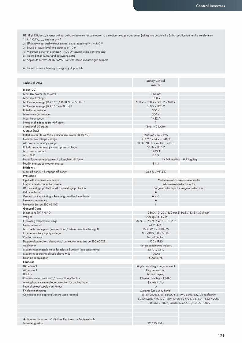
Input (DC)Max. DC power (@ cos ϕ=1)Max. input voltageMPP voltage range (@ 25 °C / @ 50 °C at 50 Hz) 1)
MPP voltage range (@ 25 °C at 60 Hz) 1)
Rated input voltageMinimum input voltageMax. input currentNumber of independent MPP inputsNumber of DC inputsOutput (AC)Rated power (@ 25 °C) / nominal AC power (@ 50 °C) Nominal AC voltage / rangeAC power frequency / rangeRated power frequency / rated power voltageMax. output currentMax. THDPower factor at rated power / adjustable shift factorFeed-in phases, connection phasesEffi ciency 2)
Max. effi ciency / European effi ciencyProtectionInput side disconnection deviceOutput side disconnection deviceDC overvoltage protection, AC overvoltage protectionGrid monitoringGround fault monitoring / Remote ground fault monitoringInsulation monitoringProtection (as per IEC 62103)General DataDimensions (W / H / D)WeightOperating temperature rangeNoise emission3)
Max. self-consumption (in operation) / self-consumption (at night)External auxiliary supply voltageCooling conceptDegree of protection: electronics / connection area (as per IEC 60529)ApplicationMaximum permissible value for relative humidity (non-condensing)Maximum operating altitude above MSLFresh air consumptionFeaturesDC terminalAC terminalDisplayCommunication protocols / Sunny String-MonitorAnalog inputs / overvoltage protection for analog inputsInternal power supply transformerPV plant monitoringCertifi cates and approvals (more upon request)
● Standard features ○ Optional features — Not availableType designation
121
Central Inverters
HE: High Efficiency, inverter without galvanic isolation for connection to a medium-voltage transformer (taking into account the SMA specification for the transformer)1) At 1.05 VAC, nom and cos ϕ = 1 2) Efficiency measured without internal power supply at VDC = 500 V3) Sound pressure level at a distance of 10 m4) Maximum power in a phase < 1400 W (asymmetrical consumption)5) 1x irradiation sensor and 1x pyranometer6) Applies to BDEW-MSRL/FGW/TR6: with limited dynamic grid support
Additional features: heating, emergency stop switch
Technical Data Sunny Central630HE
713 kW1000 V
500 V – 820 V / 500 V – 820 V510 V – 820 V
550 V500 V
1422 A1
(8+8) + 2 DCHV
700 kVA / 630 kVA315 V / 284 V – 346 V
50 Hz, 60 Hz / 47 Hz … 63 Hz50 Hz / 315 V
1283 A< 3 %
3 / 3
98.6 % / 98.4 %
1 / 0.9 leading ... 0.9 lagging
Motor-driven DC switch-disconnectorAC fuse-switch-disconnector
Surge arrester type II / surge arrester type I●
● / ○●I
1900 kg / 4189 lb-20 °C … +50 °C / -4 °F … +122 °F
64.2 db(A)1500 W 4) / < 100 W
Not air-conditioned indoors15 % … 95 %
1000 m6200 m³/h
Ring terminal lug / cage terminalRing terminal lugLC text display
Ethernet, modbus / RS4852 x Ain 5) / ○
○Optional (via Sunny Portal)
SC 630HE-11
IP20 / IP20
EN 61000-6-2, EN 61000-6-4, EMC conformity, CE conformity, BDEW-MSRL / FGW / TR8⁶⁾, Arrêté du 4/23/08, R.D. 1663 / 2000,
R.D. 661 / 2007, Golden Sun CGC / GF 001:2009
2800 / 2120 / 850 mm (110.3 / 83.5 / 33.5 inch)
3 x 230 V, 50 / 60 Hz Forced cooling
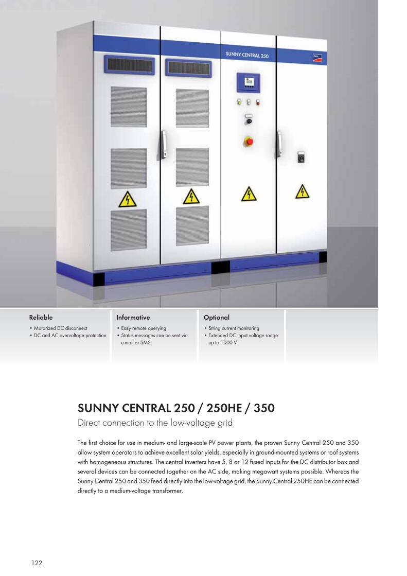
122
SUNNY CENTRAL 250 / 250HE / 350 Direct connection to the low-voltage gridThe first choice for use in medium- and large-scale PV power plants, the proven Sunny Central 250 and 350 allow system operators to achieve excellent solar yields, especially in ground-mounted systems or roof systems with homogeneous structures. The central inverters have 5, 8 or 12 fused inputs for the DC distributor box and several devices can be connected together on the AC side, making megawatt systems possible. Whereas the Sunny Central 250 and 350 feed directly into the low-voltage grid, the Sunny Central 250HE can be connected directly to a medium-voltage transformer.
Reliable• Motorized DC disconnect • DC and AC overvoltage protection
Informative• Easy remote querying • Status messages can be sent via
e-mail or SMS
Optional• String current monitoring• Extended DC input voltage range
up to 1000 V
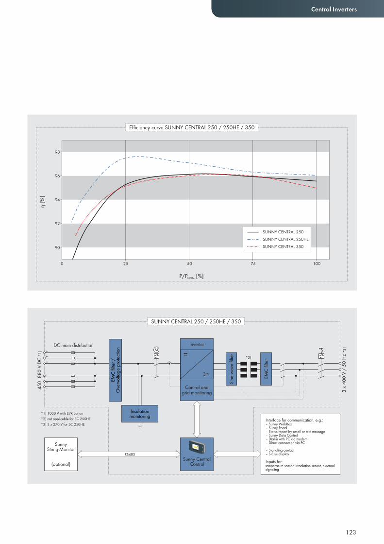
123
Central Inverters
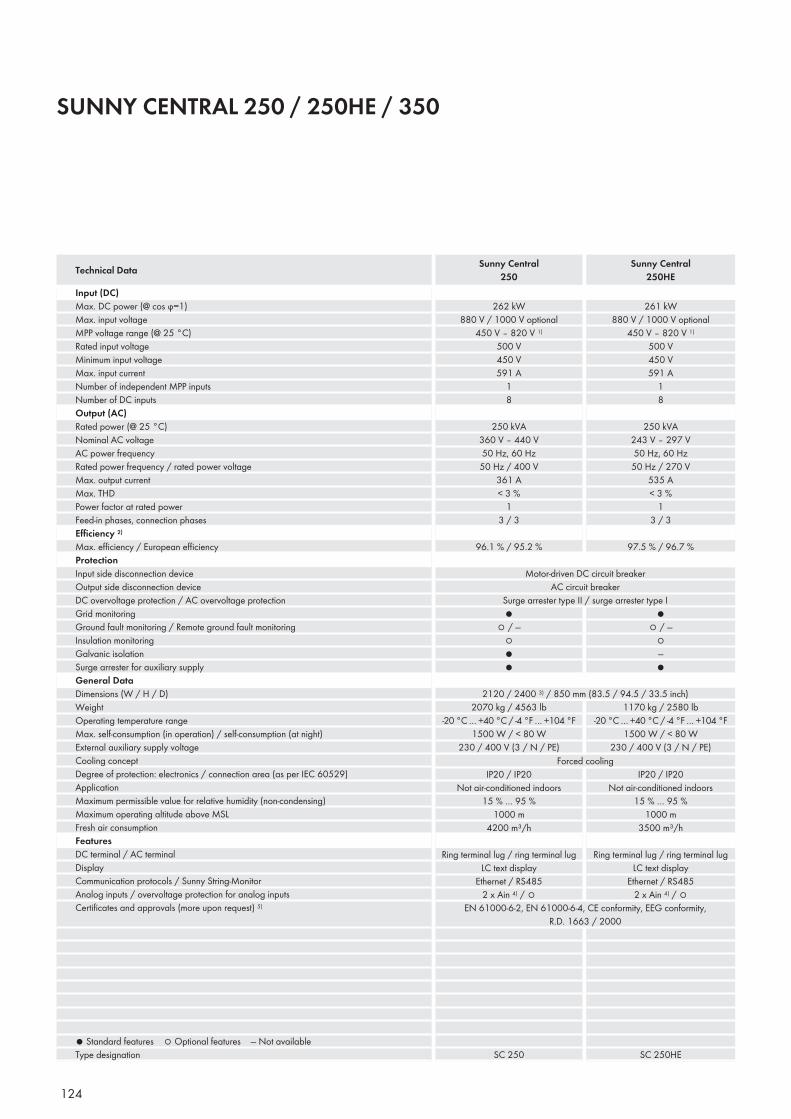
124
SUNNY CENTRAL 250 / 250HE / 350
Input (DC)Max. DC power (@ cos ϕ=1)Max. input voltageMPP voltage range (@ 25 °C)Rated input voltageMinimum input voltageMax. input currentNumber of independent MPP inputsNumber of DC inputsOutput (AC)Rated power (@ 25 °C)Nominal AC voltageAC power frequencyRated power frequency / rated power voltageMax. output currentMax. THDPower factor at rated powerFeed-in phases, connection phasesEffi ciency 2)
Max. effi ciency / European effi ciencyProtectionInput side disconnection deviceOutput side disconnection deviceDC overvoltage protection / AC overvoltage protectionGrid monitoringGround fault monitoring / Remote ground fault monitoringInsulation monitoringGalvanic isolationSurge arrester for auxiliary supplyGeneral DataDimensions (W / H / D)WeightOperating temperature rangeMax. self-consumption (in operation) / self-consumption (at night)External auxiliary supply voltage Cooling conceptDegree of protection: electronics / connection area (as per IEC 60529)ApplicationMaximum permissible value for relative humidity (non-condensing)Maximum operating altitude above MSLFresh air consumptionFeaturesDC terminal / AC terminalDisplayCommunication protocols / Sunny String-MonitorAnalog inputs / overvoltage protection for analog inputsCertifi cates and approvals (more upon request) 5)
● Standard features ○ Optional features — Not availableType designation
Technical Data Sunny Central250
Sunny Central250HE
262 kW880 V / 1000 V optional
450 V – 820 V 1)
500 V450 V591 A
18
250 kVA 360 V – 440 V50 Hz, 60 Hz
50 Hz / 400 V361 A< 3 %
13 / 3
96.1 % / 95.2 %
261 kW880 V / 1000 V optional
450 V – 820 V 1)
500 V450 V591 A
18
250 kVA243 V – 297 V50 Hz, 60 Hz
50 Hz / 270 V535 A< 3 %
13 / 3
97.5 % / 96.7 %
Motor-driven DC circuit breakerAC circuit breaker
Surge arrester type II / surge arrester type I●
○ / —○●●
●○ / —
○—●
2070 kg / 4563 lb-20 °C … +40 °C / -4 °F … +104 °F
1500 W / < 80 W230 / 400 V (3 / N / PE)
1170 kg / 2580 lb-20 °C … +40 °C / -4 °F … +104 °F
1500 W / < 80 W230 / 400 V (3 / N / PE)
IP20 / IP20Not air-conditioned indoors
15 % … 95 %1000 m
4200 m³/h
Ring terminal lug / ring terminal lugLC text display
Ethernet / RS4852 x Ain 4) / ○
IP20 / IP20Not air-conditioned indoors
15 % … 95 %1000 m
3500 m³/h
Ring terminal lug / ring terminal lugLC text display
Ethernet / RS4852 x Ain 4) / ○
SC 250 SC 250HE
Forced cooling
EN 61000-6-2, EN 61000-6-4, CE conformity, EEG conformity, R.D. 1663 / 2000
2120 / 2400 3) / 850 mm (83.5 / 94.5 / 33.5 inch)
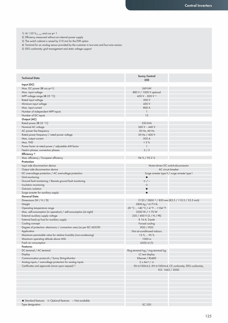
125
Central Inverters
1) At 1.05 VAC, nom and cos ϕ= 12) Efficiency measured without an internal power supply3) The switch cabinet is raised by 210 mm for the EVR option4) Terminal for an analog sensor provided by the customer in two-wire and four-wire version5) EEG conformity: grid management and static voltage support
Input (DC)Max. DC power (@ cos ϕ=1)Max. input voltageMPP voltage range (@ 25 °C)Rated input voltageMinimum input voltageMax. input currentNumber of independent MPP inputsNumber of DC inputsOutput (AC)Rated power (@ 25 °C)Nominal AC voltageAC power line frequencyRated power frequency / rated power voltageMax. output currentMax. THDPower factor at rated power / adjustable shift factorFeed-in phases, connection phasesEffi ciency 2)
Max. effi ciency / European effi ciencyProtectionInput side disconnection deviceOutput side disconnection deviceDC overvoltage protection / AC overvoltage protectionGrid monitoringGround fault monitoring / Remote ground fault monitoringInsulation monitoringGalvanic isolationSurge arrester for auxiliary supplyGeneral DataDimensions (W / H / D)WeightOperating temperature rangeMax. self-consumption (in operation) / self-consumption (at night)External auxiliary supply voltageExternal back-up fuse for auxiliary supplyCooling conceptDegree of protection: electronics / connection area (as per IEC 60529)ApplicationMaximum permissible value for relative humidity (non-condensing)Maximum operating altitude above MSLFresh air consumptionFeaturesDC terminal / AC terminalDisplayCommunication protocols / Sunny String-MonitorAnalog inputs / overvoltage protection for analog inputsCertifi cates and approvals (more upon request) 5)
● Standard features ○ Optional features — Not availableType designation
Technical Data Sunny Central350
369 kW880 V / 1000 V optional
450 V – 820 V 1)
500 V450 V800 A
112
350 kVA 360 V – 440 V50 Hz, 60 Hz
50 Hz / 400 V505 A< 3 %
13 / 3
96 % / 95.2 %
Motor-driven DC switch-disconnectorAC circuit breaker
Surge arrester type II / surge arrester type I●
○ / —○●●
2800 kg / 6173 lb-20 °C … +40 °C / -4 °F … +104 °F
2500 W / < 70 W
IP20 / IP20Not air-conditioned indoors
15 % … 95 %1000 m
6500 m³/h
Ring terminal lug / ring terminal lugLC text display
Ethernet / RS4852 x Ain4) / ○
SC 350
Forced cooling
EN 61000-6-2, EN 61000-6-4, CE conformity, EEG conformity, R.D. 1663 / 2000
2120 / 2800 3) / 850 mm (83.5 / 110.3 / 33.5 inch)
230 / 400 V (3 / N / PE) B 16 A, 3-pole
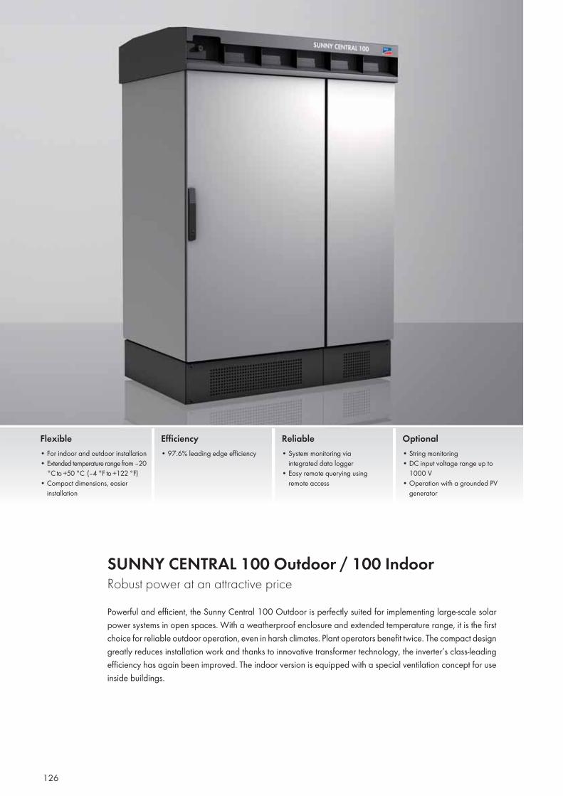
126
SUNNY CENTRAL 100 Outdoor / 100 Indoor Robust power at an attractive pricePowerful and efficient, the Sunny Central 100 Outdoor is perfectly suited for implementing large-scale solar power systems in open spaces. With a weatherproof enclosure and extended temperature range, it is the first choice for reliable outdoor operation, even in harsh climates. Plant operators benefit twice. The compact design greatly reduces installation work and thanks to innovative transformer technology, the inverter’s class-leading efficiency has again been improved. The indoor version is equipped with a special ventilation concept for use inside buildings.
Flexible• For indoor and outdoor installation • Extended temperature range from –20
°C to +50 °C (–4 °F to +122 °F)• Compact dimensions, easier
installation
Efficiency• 97.6% leading edge efficiency
Reliable• System monitoring via
integrated data logger• Easy remote querying using
remote access
Optional• String monitoring• DC input voltage range up to
1000 V• Operation with a grounded PV
generator
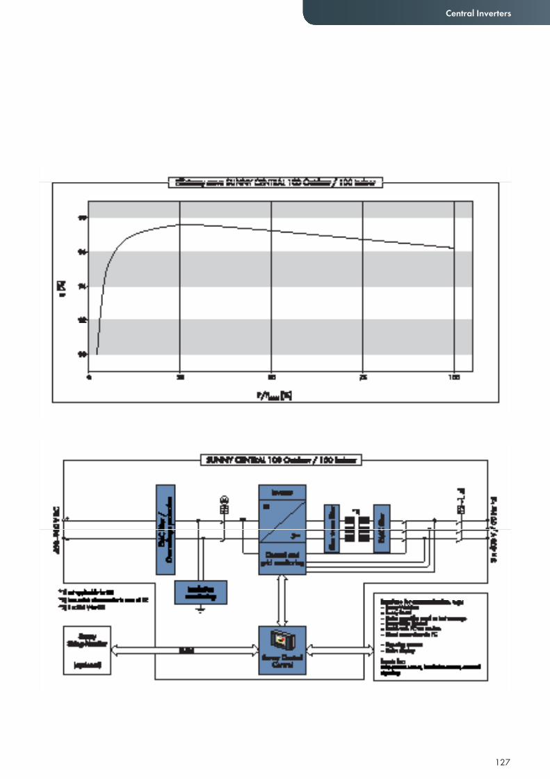
127
Central Inverters
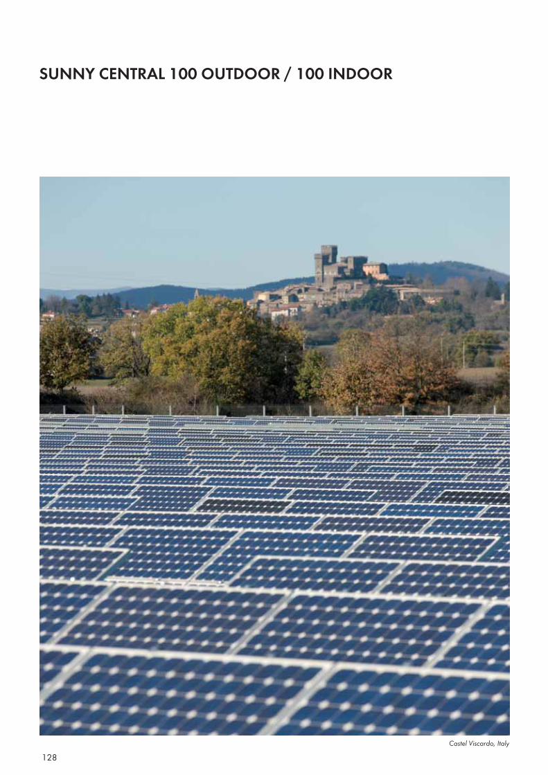
128
SUNNY CENTRAL 100 OUTDOOR / 100 INDOOR
Castel Viscardo, Italy
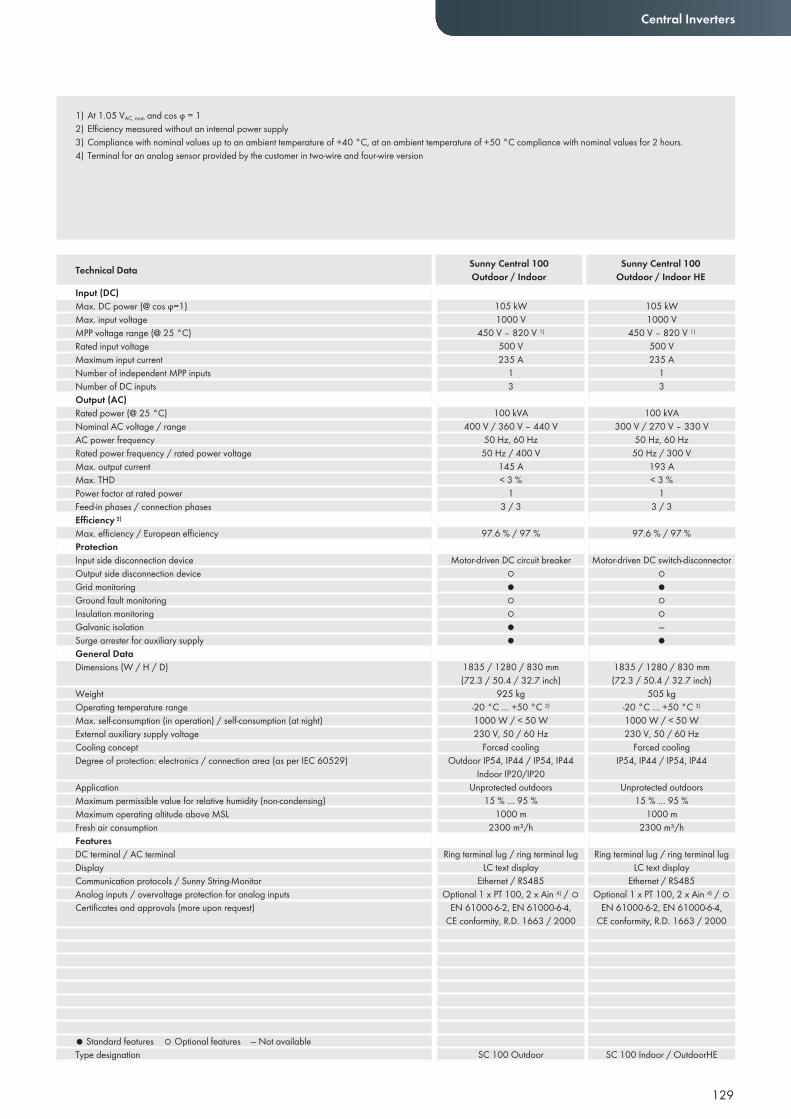
Central Inverters
1) At 1.05 VAC, nom and cos ϕ = 12) Efficiency measured without an internal power supply3) Compliance with nominal values up to an ambient temperature of +40 °C, at an ambient temperature of +50 °C compliance with nominal values for 2 hours.4) Terminal for an analog sensor provided by the customer in two-wire and four-wire version
Input (DC)Max. DC power (@ cos ϕ=1)Max. input voltageMPP voltage range (@ 25 °C)Rated input voltageMaximum input currentNumber of independent MPP inputsNumber of DC inputsOutput (AC)Rated power (@ 25 °C)Nominal AC voltage / rangeAC power frequencyRated power frequency / rated power voltageMax. output currentMax. THDPower factor at rated powerFeed-in phases / connection phasesEffi ciency 2)
Max. effi ciency / European effi ciencyProtectionInput side disconnection deviceOutput side disconnection deviceGrid monitoringGround fault monitoringInsulation monitoringGalvanic isolationSurge arrester for auxiliary supplyGeneral DataDimensions (W / H / D)
WeightOperating temperature rangeMax. self-consumption (in operation) / self-consumption (at night)External auxiliary supply voltage Cooling conceptDegree of protection: electronics / connection area (as per IEC 60529)
ApplicationMaximum permissible value for relative humidity (non-condensing)Maximum operating altitude above MSLFresh air consumptionFeaturesDC terminal / AC terminalDisplayCommunication protocols / Sunny String-MonitorAnalog inputs / overvoltage protection for analog inputsCertifi cates and approvals (more upon request)
● Standard features ○ Optional features — Not availableType designation
Technical Data Sunny Central 100Outdoor / Indoor
Sunny Central 100Outdoor / Indoor HE
105 kW1000 V
450 V – 820 V 1)
500 V235 A
13
100 kVA400 V / 360 V – 440 V
50 Hz, 60 Hz50 Hz / 400 V
145 A< 3 %
13 / 3
97.6 % / 97 %
Motor-driven DC circuit breaker○●○○●●
1835 / 1280 / 830 mm(72.3 / 50.4 / 32.7 inch)
925 kg-20 °C … +50 °C 3)
1000 W / < 50 W230 V, 50 / 60 Hz
Forced coolingOutdoor IP54, IP44 / IP54, IP44
Unprotected outdoors15 % … 95 %
1000 m2300 m³/h
Ring terminal lug / ring terminal lugLC text display
Ethernet / RS485Optional 1 x PT 100, 2 x Ain 4) / ○
EN 61000-6-2, EN 61000-6-4, CE conformity, R.D. 1663 / 2000
SC 100 Outdoor
105 kW1000 V
450 V – 820 V 1)
500 V235 A
13
100 kVA300 V / 270 V – 330 V
50 Hz, 60 Hz50 Hz / 300 V
193 A< 3 %
13 / 3
97.6 % / 97 %
Motor-driven DC switch-disconnector○●○○—●
1835 / 1280 / 830 mm(72.3 / 50.4 / 32.7 inch)
505 kg-20 °C … +50 °C 3)
1000 W / < 50 W230 V, 50 / 60 Hz
Forced coolingIP54, IP44 / IP54, IP44
Unprotected outdoors15 % … 95 %
1000 m2300 m³/h
Ring terminal lug / ring terminal lugLC text display
Ethernet / RS485Optional 1 x PT 100, 2 x Ain 4) / ○
EN 61000-6-2, EN 61000-6-4, CE conformity, R.D. 1663 / 2000
SC 100 Indoor / OutdoorHE
Indoor IP20/IP20
129
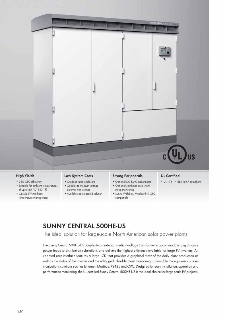
130
SUNNY CENTRAL 500HE-US The ideal solution for large-scale North American solar power plantsThe Sunny Central 500HE-US couples to an external medium-voltage transformer to accommodate long distance power feeds to distribution substations and delivers the highest efficiency available for large PV inverters. An updated user interface features a large LCD that provides a graphical view of the daily plant production as well as the status of the inverter and the utility grid. Flexible plant monitoring is available through various com-munications solutions such as Ethernet, Modbus, RS485 and OPC. Designed for easy installation, operation and performance monitoring, the UL-certified Sunny Central 500HE-US is the ideal choice for large-scale PV projects.
High Yields• 98% CEC efficiency• Suitable for ambient temperatures
of up to 60 °C (140 °F)• OptiCool™ intelligent
temperature management
Low System Costs• Outdoor-rated enclosure• Couples to medium-voltage
external transformer• Available as integrated solution
Strong Peripherals• Optional DC & AC disconnects• Optional combiner boxes with
string monitoring • Sunny WebBox, Modbus® & OPC
compatible
UL Certified• UL 1741 / IEEE-1547 compliant
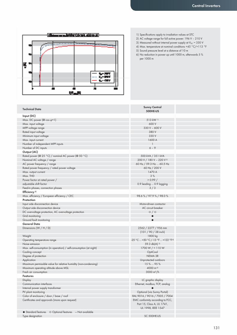
131
Central Inverters
Input (DC)Max. DC power (@ cos ϕ=1)Max. input voltageMPP voltage rangeRated input voltageMinimum input voltageMax. input currentNumber of independent MPP inputsNumber of DC inputsOutput (AC)Rated power (@ 25 °C) / nominal AC power (@ 50 °C) Nominal AC voltage / rangeAC power frequency / rangeRated power frequency / rated power voltageMax. output currentMax. THDPower factor at rated power / adjustable shift factorFeed-in phases, connection phasesEffi ciency 3)
Max. effi ciency / European effi ciency / CECProtectionInput side disconnection deviceOutput side disconnection deviceDC overvoltage protection, AC overvoltage protectionGrid monitoringGround fault monitoringGeneral DataDimensions (W / H / D)
WeightOperating temperature rangeNoise emissionMax. self-consumption (in operation) / self-consumption (at night)Cooling conceptDegree of protectionApplicationMaximum permissible value for relative humidity (non-condensing)Maximum operating altitude above MSLFresh air consumptionFeaturesDisplayCommunication interfacesInternal power supply transformerPV plant monitoring Color of enclosure / door / base / roofCertifi cates and approvals (more upon request)
● Standard features ○ Optional features — Not availableType designation
Technical Data Sunny Central500HE-US
513 kW 1)
600 V330 V – 600 V
380 V330 V
1600 A1
6 – 9
500 kVA / 351 kVA200 V / 180 V – 220 V 2)
60 Hz / 59.3 Hz … 60.5 Hz60 Hz / 200 V
1470 A3 %
> 0.99 / 0.9 leading ... 0.9 lagging
3 / 3
98.6 % / 97.9 % / 98.0 %
Motor-driven contactorAC circuit breaker
○ / ○●●
2562 / 2277 / 956 mm (101 / 90 / 38 inch)
1800 kg-25 °C … +50 °C / -13 °F … +122 °F 4)
59.3 db(A) 5)
1700 W / < 110 WOptiCoolNEMA 3R
Unprotected outdoors15 % … 95 %
4000 m 6)
3000 m³/h
LC graphic displayEthernet, modbus, TCP, analog
●Optional (via Sunny Portal)
RAL 9016 / 9016 / 7005 / 7004EMC conformity according to FCC,
Part 15, Class A, UL 1741, UL 1998, IEEE 1547
SC 500HE-US
1) Specifications apply to irradiation values at STC2) AC voltage range for full active power: 196 V – 210 V3) Measured without internal power supply at VDC = 330 V4) Max. temperature at nominal conditions +45 °C/+113 °F5) Sound pressure level at a distance of 10 m6) No reduction in power up until 1000 m, afterwards 5 %
per 1000 m
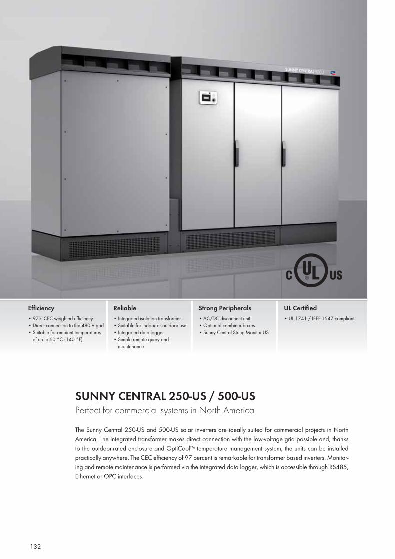
132
SUNNY CENTRAL 250-US / 500-USPerfect for commercial systems in North AmericaThe Sunny Central 250-US and 500-US solar inverters are ideally suited for commercial projects in North America. The integrated transformer makes direct connection with the low-voltage grid possible and, thanks to the outdoor-rated enclosure and OptiCool™ temperature management system, the units can be installed practically anywhere. The CEC efficiency of 97 percent is remarkable for transformer based inverters. Monitor-ing and remote maintenance is performed via the integrated data logger, which is accessible through RS485, Ethernet or OPC interfaces.
Efficiency• 97% CEC weighted efficiency• Direct connection to the 480 V grid• Suitable for ambient temperatures
of up to 60 °C (140 °F)
Reliable• Integrated isolation transformer • Suitable for indoor or outdoor use• Integrated data logger • Simple remote query and
maintenance
Strong Peripherals• AC/DC disconnect unit• Optional combiner boxes• Sunny Central String-Monitor-US
UL Certified• UL 1741 / IEEE-1547 compliant
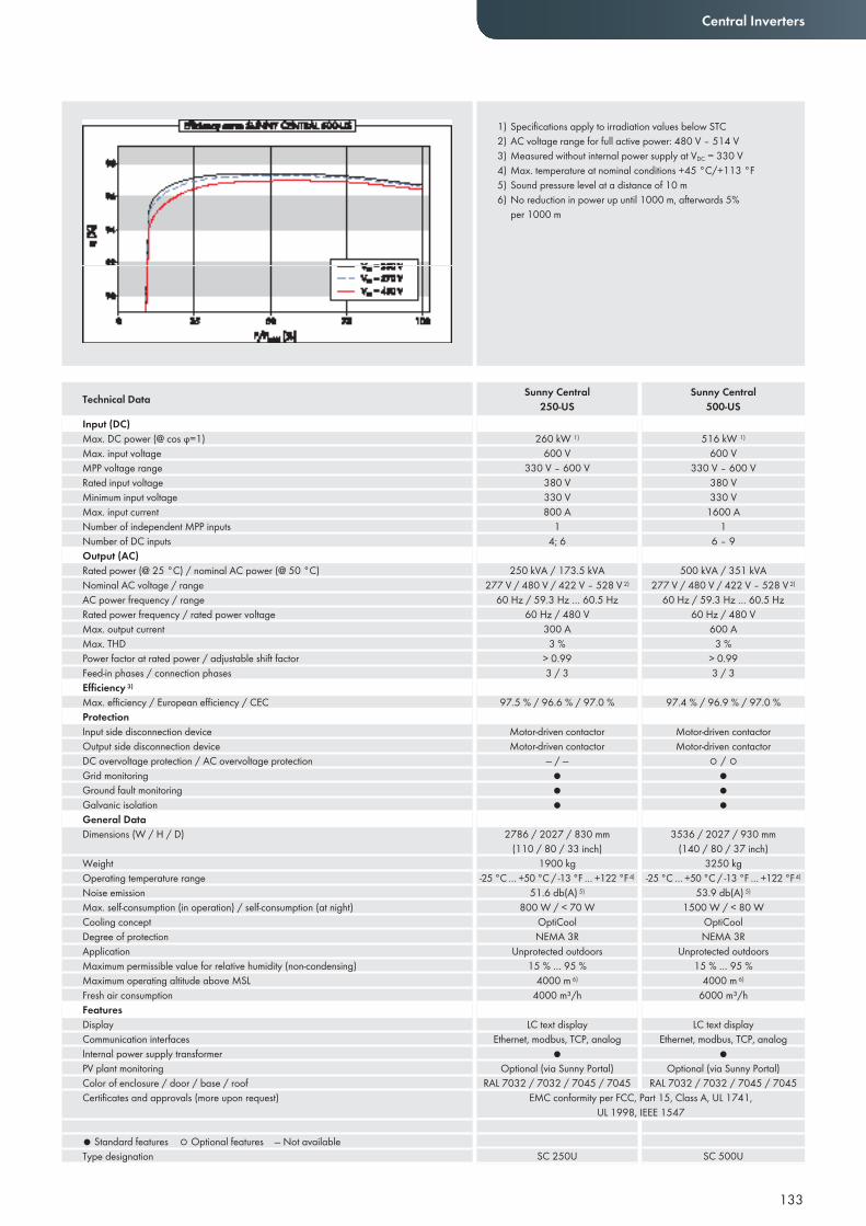
133
Central Inverters
Input (DC)Max. DC power (@ cos ϕ=1)Max. input voltageMPP voltage rangeRated input voltageMinimum input voltageMax. input currentNumber of independent MPP inputsNumber of DC inputsOutput (AC)Rated power (@ 25 °C) / nominal AC power (@ 50 °C) Nominal AC voltage / rangeAC power frequency / rangeRated power frequency / rated power voltageMax. output currentMax. THDPower factor at rated power / adjustable shift factorFeed-in phases / connection phasesEffi ciency 3)
Max. effi ciency / European effi ciency / CECProtectionInput side disconnection deviceOutput side disconnection deviceDC overvoltage protection / AC overvoltage protectionGrid monitoringGround fault monitoringGalvanic isolationGeneral DataDimensions (W / H / D)
WeightOperating temperature rangeNoise emissionMax. self-consumption (in operation) / self-consumption (at night)Cooling conceptDegree of protectionApplicationMaximum permissible value for relative humidity (non-condensing)Maximum operating altitude above MSLFresh air consumptionFeaturesDisplayCommunication interfacesInternal power supply transformerPV plant monitoringColor of enclosure / door / base / roofCertifi cates and approvals (more upon request)
● Standard features ○ Optional features — Not availableType designation
260 kW 1)
600 V330 V – 600 V
380 V330 V800 A
14; 6
250 kVA / 173.5 kVA277 V / 480 V / 422 V – 528 V 2)
60 Hz / 59.3 Hz … 60.5 Hz60 Hz / 480 V
300 A3 %
> 0.993 / 3
97.5 % / 96.6 % / 97.0 %
Motor-driven contactorMotor-driven contactor
— / —●●●
2786 / 2027 / 830 mm (110 / 80 / 33 inch)
1900 kg-25 °C … +50 °C / -13 °F … +122 °F 4)
51.6 db(A) 5)
800 W / < 70 WOptiCoolNEMA 3R
Unprotected outdoors15 % … 95 %
4000 m 6)
4000 m³/h
LC text displayEthernet, modbus, TCP, analog
●Optional (via Sunny Portal)
RAL 7032 / 7032 / 7045 / 7045
516 kW 1)
600 V330 V – 600 V
380 V330 V
1600 A1
6 – 9
500 kVA / 351 kVA277 V / 480 V / 422 V – 528 V 2)
60 Hz / 59.3 Hz … 60.5 Hz60 Hz / 480 V
600 A3 %
> 0.993 / 3
97.4 % / 96.9 % / 97.0 %
Motor-driven contactorMotor-driven contactor
○ / ○●●●
3536 / 2027 / 930 mm (140 / 80 / 37 inch)
3250 kg-25 °C … +50 °C / -13 °F … +122 °F 4)
53.9 db(A) 5)
1500 W / < 80 WOptiCoolNEMA 3R
Unprotected outdoors15 % … 95 %
4000 m 6)
6000 m³/h
LC text displayEthernet, modbus, TCP, analog
●Optional (via Sunny Portal)
RAL 7032 / 7032 / 7045 / 7045
Technical Data Sunny Central250-US
Sunny Central500-US
EMC conformity per FCC, Part 15, Class A, UL 1741, UL 1998, IEEE 1547
SC 250U SC 500U
1) Specifications apply to irradiation values below STC2) AC voltage range for full active power: 480 V – 514 V3) Measured without internal power supply at VDC = 330 V4) Max. temperature at nominal conditions +45 °C/+113 °F5) Sound pressure level at a distance of 10 m6) No reduction in power up until 1000 m, afterwards 5%
per 1000 m
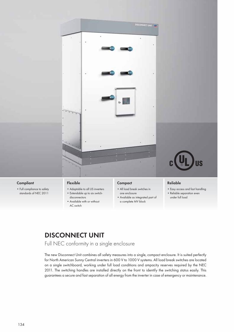
134
DISCONNECT UNITFull NEC conformity in a single enclosureThe new Disconnect Unit combines all safety measures into a single, compact enclosure. It is suited perfectly for North American Sunny Central inverters in 600 V to 1000 V systems. All load break switches are located on a single switchboard, working under full load conditions and ampacity reserves required by the NEC 2011. The switching handles are installed directly on the front to identify the switching status easily. This guarantees a secure and fast separation of all energy from the inverter in case of emergency or maintenance.
Compliant• Full compliance to safety standards of NEC 2011
Flexible• Adaptable to all US inverters • Extendable up to six switch- disconnectors• Available with or without AC switch
Compact• All load break switches in one enclosure• Available as integrated part of a complete MV block
Reliable• Easy access and fast handling• Reliable separation even under full load
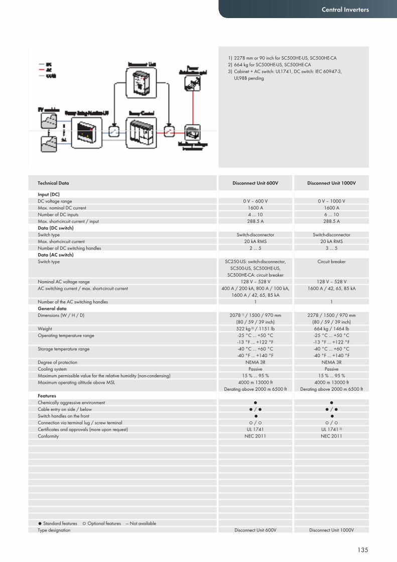
135
Central Inverters
Input (DC)DC voltage rangeMax. nominal DC currentNumber of DC inputsMax. short-circuit current / inputData (DC switch)Switch typeMax. short-circuit currentNumber of DC switching handlesData (AC switch)Switch type
Nominal AC voltage rangeAC switching current / max. short-circuit current
Number of the AC switching handlesGeneral data Dimensions (W / H / D)
WeightOperating temperature range
Storage temperature range
Degree of protectionCooling systemMaximum permissible value for the relative humidity (non-condensing)Maximum operating altitude above MSL
FeaturesChemically aggressive environmentCable entry on side / belowSwitch handles on the frontConnection via terminal lug / screw terminalCertifi cates and approvals (more upon request) Conformity
● Standard features ○ Optional features — Not availableType designation
0 V – 600 V1600 A4 … 10288.5 A
Switch-disconnector20 kA RMS
2 … 5
SC250-US: switch-disconnector, SC500-US, SC500HE-US,
SC500HE-CA: circuit breaker128 V – 528 V
400 A / 200 kA, 800 A / 100 kA, 1600 A / 42, 65, 85 kA
1
2078 1) / 1500 / 970 mm(80 / 59 / 39 inch)522 kg 2) / 1151 lb-25 °C … +50 °C-13 °F … +122 °F-40 °C … +60 °C-40 °F … +140 °F
NEMA 3RPassive
15 % … 95 %4000 m 13000 ft
Derating above 2000 m 6500 ft
●● / ●
●○ / ○
UL 1741 NEC 2011
Disconnect Unit 600V
0 V – 1000 V1600 A6 … 10288.5 A
Switch-disconnector20 kA RMS
3 … 5
Circuit breaker
128 V – 528 V1600 A / 42, 65, 85 kA
1
2278 / 1500 / 970 mm(80 / 59 / 39 inch)664 kg / 1464 lb-25 °C … +50 °C-13 °F … +122 °F-40 °C … +60 °C-40 °F … +140 °F
NEMA 3RPassive
15 % … 95 %4000 m 13000 ft
Derating above 2000 m 6500 ft
●● / ●
●○ / ○
UL 1741 3) NEC 2011
Disconnect Unit 1000V
Technical Data Disconnect Unit 600V Disconnect Unit 1000V
1) 2278 mm or 90 inch for SC500HE-US, SC500HE-CA2) 664 kg for SC500HE-US, SC500HE-CA3) Cabinet + AC switch: UL1741, DC switch: IEC 60947-3,
UL98B pending
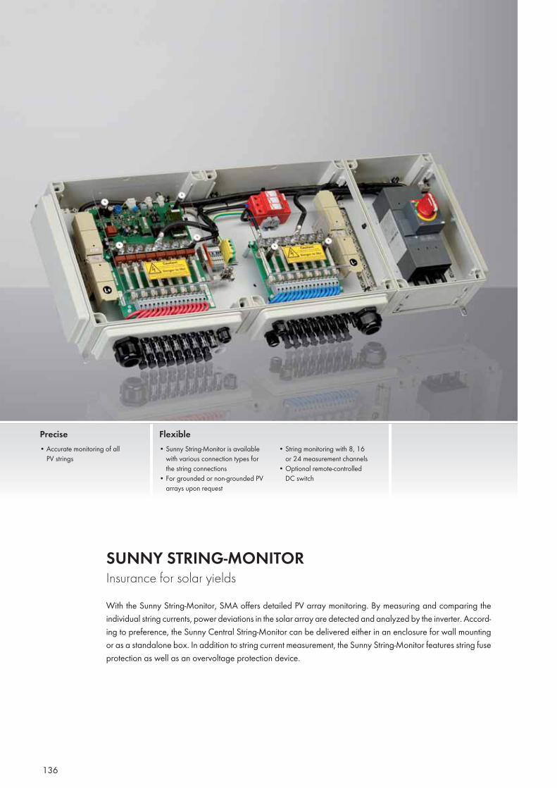
136
SUNNY STRING-MONITORInsurance for solar yieldsWith the Sunny String-Monitor, SMA offers detailed PV array monitoring. By measuring and comparing the individual string currents, power deviations in the solar array are detected and analyzed by the inverter. Accord-ing to preference, the Sunny Central String-Monitor can be delivered either in an enclosure for wall mounting or as a standalone box. In addition to string current measurement, the Sunny String-Monitor features string fuse protection as well as an overvoltage protection device.
Precise• Accurate monitoring of all
PV strings
Flexible• Sunny String-Monitor is available
with various connection types for the string connections
• For grounded or non-grounded PV arrays upon request
• String monitoring with 8, 16 or 24 measurement channels
• Optional remote-controlled DC switch
Montalto di Castro, Italy
137
Central Inverters
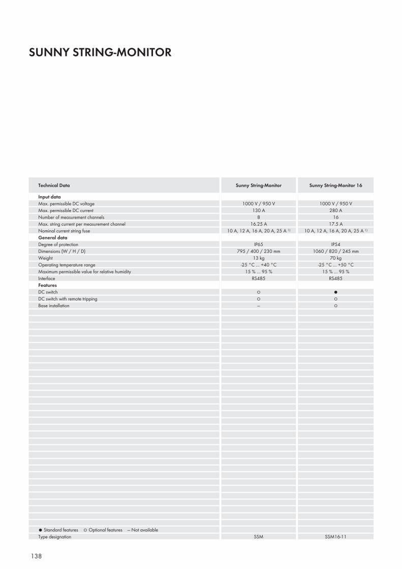
138
SUNNY STRING-MONITOR
Input dataMax. permissible DC voltageMax. permissible DC currentNumber of measurement channelsMax. string current per measurement channelNominal current string fuseGeneral dataDegree of protectionDimensions (W / H / D)WeightOperating temperature rangeMaximum permissible value for relative humidityInterfaceFeaturesDC switchDC switch with remote trippingBase installation
● Standard features ○ Optional features — Not availableType designation
1000 V / 950 V130 A
816.25 A
10 A, 12 A, 16 A, 20 A, 25 A 1)
IP65795 / 400 / 230 mm
13 kg-25 °C … +40 °C
15 % … 95 %RS485
○○—
SSM
1000 V / 950 V280 A
1617.5 A
10 A, 12 A, 16 A, 20 A, 25 A 1)
IP541060 / 820 / 245 mm
70 kg-25 °C … +50 °C
15 % … 95 %RS485
●○○
SSM16-11
Technical Data Sunny String-Monitor Sunny String-Monitor 16
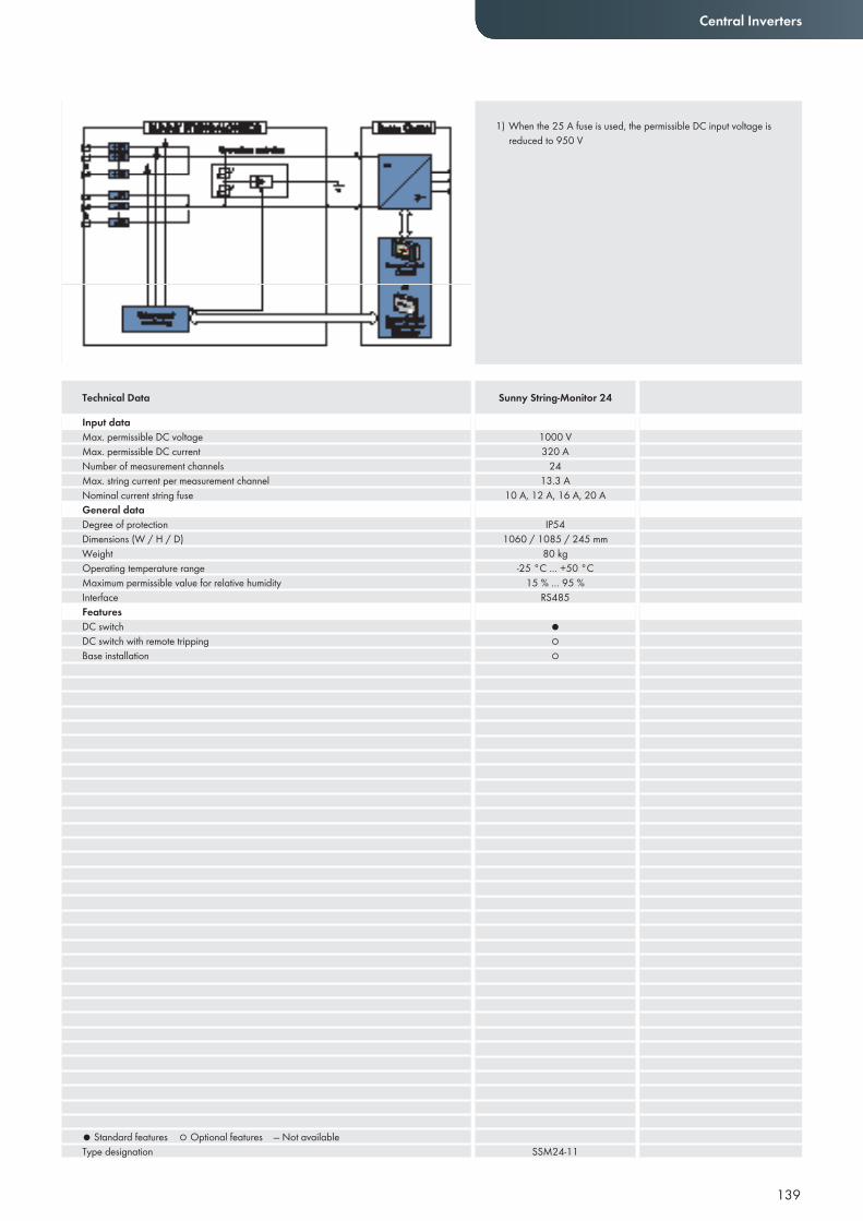
139
Central Inverters
Input dataMax. permissible DC voltageMax. permissible DC currentNumber of measurement channelsMax. string current per measurement channelNominal current string fuseGeneral dataDegree of protectionDimensions (W / H / D)WeightOperating temperature rangeMaximum permissible value for relative humidityInterfaceFeaturesDC switchDC switch with remote trippingBase installation
● Standard features ○ Optional features — Not availableType designation
1000 V320 A
2413.3 A
10 A, 12 A, 16 A, 20 A
IP541060 / 1085 / 245 mm
80 kg-25 °C … +50 °C
15 % … 95 %RS485
●○○
SSM24-11
Technical Data Sunny String-Monitor 24
1) When the 25 A fuse is used, the permissible DC input voltage is reduced to 950 V
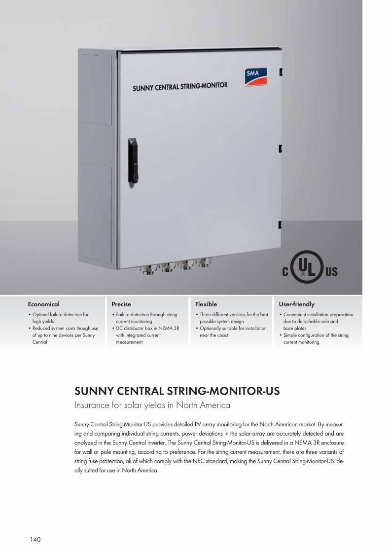
140
SUNNY CENTRAL STRING-MONITOR-USInsurance for solar yields in North AmericaSunny Central String-Monitor-US provides detailed PV array monitoring for the North American market. By measur-ing and comparing individual string currents, power deviations in the solar array are accurately detected and are analyzed in the Sunny Central inverter. The Sunny Central String-Monitor-US is delivered in a NEMA 3R enclosure for wall or pole mounting, according to preference. For the string current measurement, there are three variants of string fuse protection, all of which comply with the NEC standard, making the Sunny Central String-Monitor-US ide-ally suited for use in North America.
Economical• Optimal failure detection for
high yields• Reduced system costs though use
of up to nine devices per Sunny Central
Precise• Failure detection through string
current monitoring• DC distributor box in NEMA 3R
with integrated current measurement
Flexible• Three different versions for the best
possible system design• Optionally suitable for installation
near the coast
User-friendly• Convenient installation preparation
due to detachable side and base plates
• Simple configuration of the string current monitoring
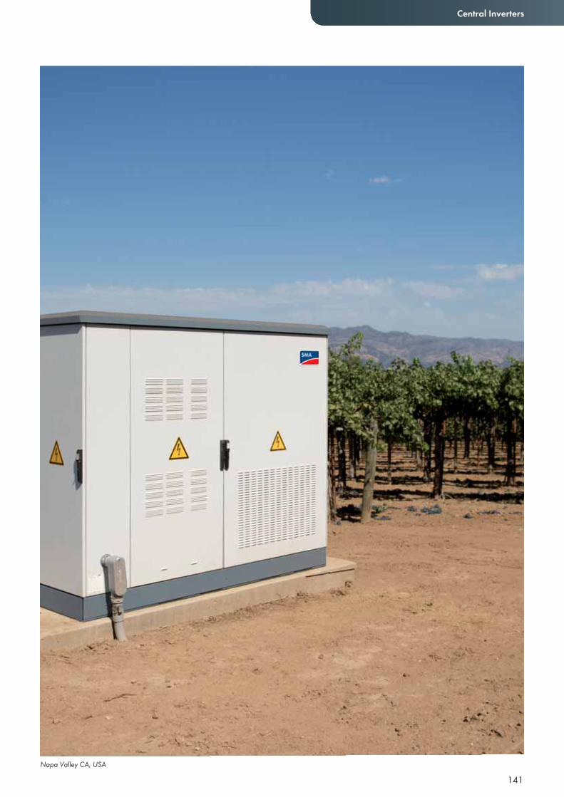
Napa Valley CA, USA
141
Central Inverters
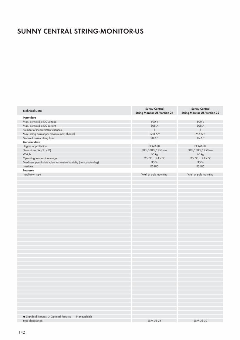
142
SUNNY CENTRAL STRING-MONITOR-US
Input dataMax. permissible DC voltageMax. permissible DC currentNumber of measurement channelsMax. string current per measurement channelNominal current string fuseGeneral dataDegree of protectionDimensions (W / H / D)WeightOperating temperature rangeMaximum permissible value for relative humidity (non-condensing)InterfaceFeaturesInstallation type
● Standard features ○ Optional features — Not availableType designation
600 V308 A
812.8 A 1)
20 A 2)
NEMA 3R800 / 800 / 250 mm
65 kg-25 °C … +45 °C
95 %RS485
Wall or pole mounting
SSM-US 24
600 V308 A
89.6 A 1)
15 A 2)
NEMA 3R800 / 800 / 250 mm
65 kg-25 °C … +45 °C
95 %RS485
Wall or pole mounting
SSM-US 32
Technical Data Sunny Central String-Monitor-US Version 24
Sunny Central String-Monitor-US Version 32
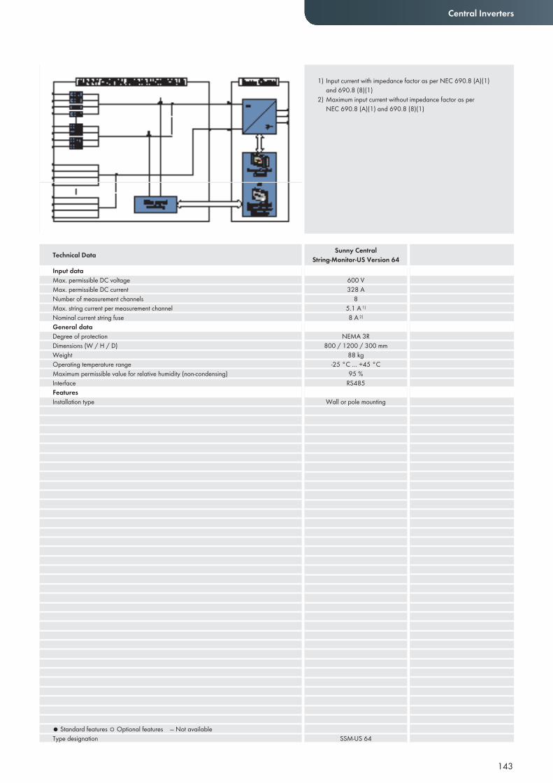
143
Central Inverters
Input dataMax. permissible DC voltageMax. permissible DC currentNumber of measurement channelsMax. string current per measurement channelNominal current string fuseGeneral dataDegree of protectionDimensions (W / H / D)WeightOperating temperature rangeMaximum permissible value for relative humidity (non-condensing)InterfaceFeaturesInstallation type
● Standard features ○ Optional features — Not availableType designation
600 V328 A
85.1 A 1)
8 A 2)
NEMA 3R800 / 1200 / 300 mm
88 kg-25 °C … +45 °C
95 %RS485
Wall or pole mounting
SSM-US 64
Technical Data Sunny Central String-Monitor-US Version 64
1) Input current with impedance factor as per NEC 690.8 (A)(1) and 690.8 (8)(1)
2) Maximum input current without impedance factor as per NEC 690.8 (A)(1) and 690.8 (8)(1)
144

MONITORING SYSTEMS
145
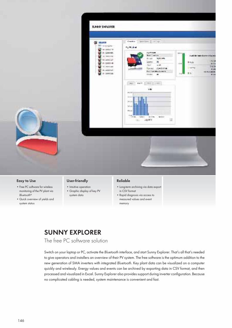
146
SUNNY EXPLORER The free PC software solutionSwitch on your laptop or PC, activate the Bluetooth interface, and start Sunny Explorer. That’s all that’s needed to give operators and installers an overview of their PV system. The free software is the optimum addition to the new generation of SMA inverters with integrated Bluetooth. Key plant data can be visualized on a computer quickly and wirelessly. Energy values and events can be archived by exporting data in CSV format, and then processed and visualized in Excel. Sunny Explorer also provides support during inverter configuration. Because no complicated cabling is needed, system maintenance is convenient and fast.
Easy to Use• Free PC software for wireless
monitoring of the PV plant via Bluetooth®
• Quick overview of yields and system status
User-friendly• Intuitive operation• Graphic display of key PV
system data
Reliable• Long-term archiving via data export
in CSV format• Rapid diagnosis via access to
measured values and event memory
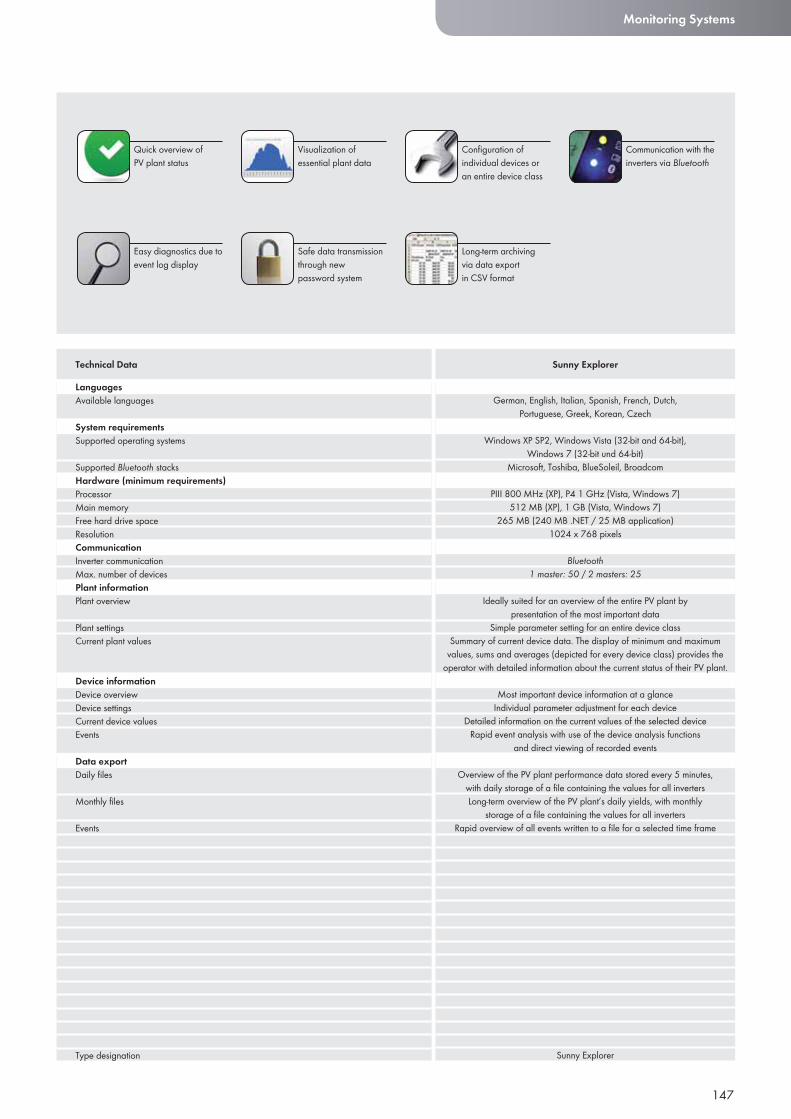
147
Monitoring Systems
LanguagesAvailable languages
System requirementsSupported operating systems
Supported Bluetooth stacksHardware (minimum requirements)ProcessorMain memoryFree hard drive spaceResolutionCommunicationInverter communicationMax. number of devicesPlant informationPlant overview
Plant settingsCurrent plant values
Device informationDevice overviewDevice settingsCurrent device valuesEvents
Data exportDaily fi les
Monthly fi les
Events
Type designation
Technical Data Sunny Explorer
Visualization of essential plant data
Quick overview of PV plant status
Safe data transmission through new password system
Confi guration of individual devices or an entire device class
Easy diagnostics due to event log display
Communication with the inverters via Bluetooth
Long-term archiving via data export in CSV format
German, English, Italian, Spanish, French, Dutch, Portuguese, Greek, Korean, Czech
Windows XP SP2, Windows Vista (32-bit and 64-bit), Windows 7 (32-bit und 64-bit)
Microsoft, Toshiba, BlueSoleil, Broadcom
PIII 800 MHz (XP), P4 1 GHz (Vista, Windows 7)512 MB (XP), 1 GB (Vista, Windows 7)
265 MB (240 MB .NET / 25 MB application)1024 x 768 pixels
Bluetooth1 master: 50 / 2 masters: 25
Ideally suited for an overview of the entire PV plant by presentation of the most important data
Simple parameter setting for an entire device classSummary of current device data. The display of minimum and maximum
values, sums and averages (depicted for every device class) provides the operator with detailed information about the current status of their PV plant.
Most important device information at a glanceIndividual parameter adjustment for each device
Detailed information on the current values of the selected deviceRapid event analysis with use of the device analysis functions
and direct viewing of recorded events
Overview of the PV plant performance data stored every 5 minutes, with daily storage of a fi le containing the values for all invertersLong-term overview of the PV plant’s daily yields, with monthly
storage of a fi le containing the values for all invertersRapid overview of all events written to a fi le for a selected time frame
Sunny Explorer

148
SUNNY BEAM with Bluetooth® Wireless TechnologyThe all-in-one service package for the homeInformative, compact, and easy to operate, the Sunny Beam with Bluetooth doesn’t just look good; it’s an in-novative monitoring solution. Key data is visible on its large graphic display, including a daily profile, current output, as well as daily and total energy yield. The performance of up to 12 inverters, the monthly overview, the energy yield in Euros or US dollars, and the CO2 savings can all be accessed with one hand. Data for a minimum of 90 days is stored in the device and can be directly transferred to a computer via a USB cable. The Sunny Beam can also be set up to emit an audio signal to notify operators of potential system errors.
User-friendly• Wireless table device with large,
easy-to-read display• USB interface for data
transfer to PC
Innovative• Automatic monitoring of up to
12 inverters via Bluetooth®
• Power supply via integrated solar cell
Easy to Use• Intuitive operation via rotary
push button• Easy-to-understand display of all
key plant data
Reliable• Audio alarm in the event of faults• Data archiving for at least 90 days
in daily files and up to 12 monthly files in CSV format
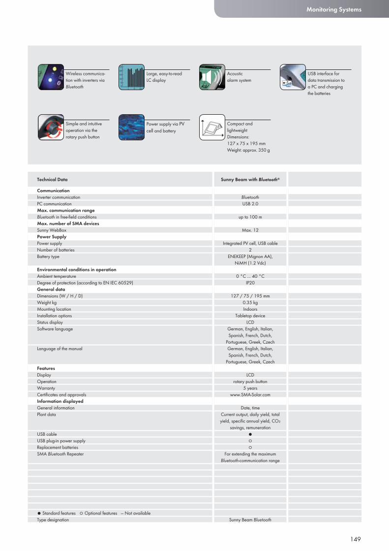
149
Monitoring Systems
CommunicationInverter communicationPC communicationMax. communication rangeBluetooth in free-fi eld conditionsMax. number of SMA devicesSunny WebBoxPower SupplyPower supplyNumber of batteriesBattery type
Environmental conditions in operationAmbient temperatureDegree of protection (according to EN IEC 60529)General dataDimensions (W / H / D)Weight kgMounting locationInstallation optionsStatus displaySoftware language
Language of the manual
FeaturesDisplayOperationWarrantyCertifi cates and approvalsInformation displayedGeneral informationPlant data
USB cableUSB plug-in power supplyReplacement batteriesSMA Bluetooth Repeater
● Standard features ○ Optional features — Not availableType designation
Technical Data Sunny Beam with Bluetooth®
Large, easy-to-readLC display
Wireless communica-tion with inverters via Bluetooth
Power supply via PV cell and battery
Acousticalarm system
Simple and intuitive operation via the rotary push button
USB interface for data transmission to a PC and charging the batteries
Compact and lightweightDimensions: 127 x 75 x 195 mmWeight: approx. 350 g
BluetoothUSB 2.0
up to 100 m
Max. 12
Integrated PV cell, USB cable2
ENEKEEP (Mignon AA), NiMH (1.2 Vdc)
0 °C … 40 °CIP20
127 / 75 / 195 mm0.35 kg Indoors
Tabletop deviceLCD
German, English, Italian, Spanish, French, Dutch,
Portuguese, Greek, CzechGerman, English, Italian, Spanish, French, Dutch,
Portuguese, Greek, Czech
LCDrotary push button
5 yearswww.SMA-Solar.com
Date, timeCurrent output, daily yield, total yield, specifi c annual yield, CO₂
savings, remuneration ●○○
For extending the maximum Bluetooth-communication range
Sunny Beam Bluetooth
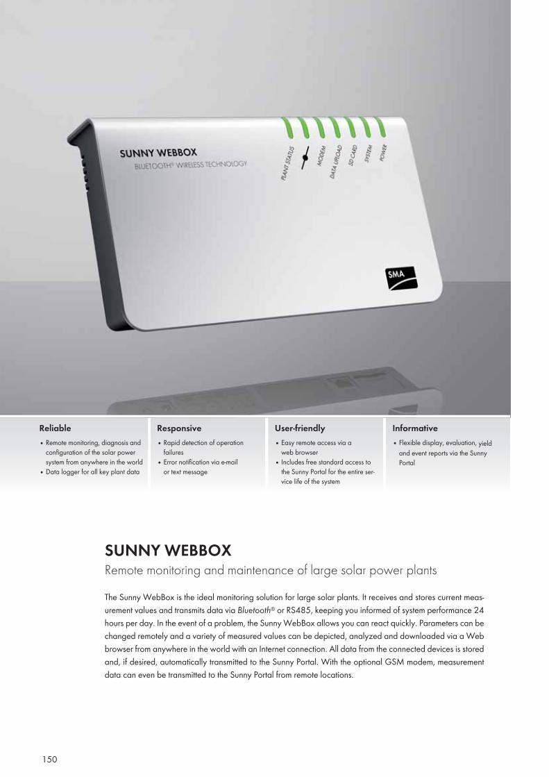
150
SUNNY WEBBOX Remote monitoring and maintenance of large solar power plantsThe Sunny WebBox is the ideal monitoring solution for large solar plants. It receives and stores current meas-urement values and transmits data via Bluetooth® or RS485, keeping you informed of system performance 24 hours per day. In the event of a problem, the Sunny WebBox allows you can react quickly. Parameters can be changed remotely and a variety of measured values can be depicted, analyzed and downloaded via a Web browser from anywhere in the world with an Internet connection. All data from the connected devices is stored and, if desired, automatically transmitted to the Sunny Portal. With the optional GSM modem, measurement data can even be transmitted to the Sunny Portal from remote locations.
Reliable• Remote monitoring, diagnosis and
configuration of the solar power system from anywhere in the world
• Data logger for all key plant data
Responsive• Rapid detection of operation
failures • Error notification via e-mail
or text message
User-friendly• Easy remote access via a
web browser• Includes free standard access to
the Sunny Portal for the entire ser-vice life of the system
Informative • Flexible display, evaluation, yield
and event reports via the Sunny Portal
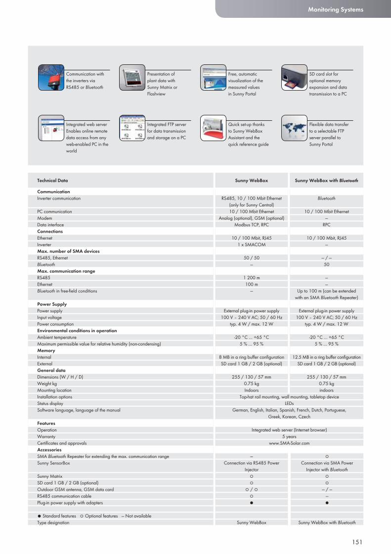
151
Monitoring Systems
CommunicationInverter communication
PC communicationModemData interfaceConnectionsEthernetInverterMax. number of SMA devicesRS485, EthernetBluetoothMax. communication rangeRS485EthernetBluetooth in free-fi eld conditions
Power SupplyPower supplyInput voltagePower consumptionEnvironmental conditions in operationAmbient temperatureMaximum permissible value for relative humidity (non-condensing)MemoryInternalExternalGeneral dataDimensions (W / H / D)Weight kgMounting locationInstallation optionsStatus displaySoftware language, language of the manual
FeaturesOperationWarrantyCertifi cates and approvalsAccessoriesSMA Bluetooth Repeater for extending the max. communication rangeSunny SensorBox
Sunny MatrixSD card 1 GB / 2 GB (optional)Outdoor GSM antenna, GSM data cardRS485 communication cablePlug-in power supply with adapters
● Standard features ○ Optional features — Not availableType designation
Technical Data
Presentation of plant data with Sunny Matrix or Flashview
Communication with the inverters via RS485 or Bluetooth
Integrated FTP server for data transmissionand storage on a PC
Free, automatic visualization of the measured values in Sunny Portal
Integrated web server Enables online remote data access from any web-enabled PC in the world
SD card slot foroptional memory expansion and data transmission to a PC
Quick set-up thanks to Sunny WebBox Assistant and the quick reference guide
Flexible data transfer to a selectable FTP server parallel to Sunny Portal
Sunny WebBox Sunny WebBox with Bluetooth
Bluetooth
10 / 100 Mbit Ethernet—
RPC
10 / 100 Mbit, RJ45—
— / —50
——
Up to 100 m (can be extended with an SMA Bluetooth Repeater)
External plug-in power supply100 V – 240 V AC; 50 / 60 Hz
typ. 4 W / max. 12 W
-20 °C … +65 °C5 % … 95 %
12.5 MB in a ring buffer confi gurationSD card 1 GB / 2 GB (optional)
255 / 130 / 57 mm0.75 kgindoors
RS485, 10 / 100 Mbit Ethernet (only for Sunny Central)10 / 100 Mbit Ethernet
Analog (optional), GSM (optional)Modbus TCP, RPC
10 / 100 Mbit, RJ451 x SMACOM
50 / 50—
1 200 m100 m
—
External plug-in power supply100 V – 240 V AC; 50 / 60 Hz
typ. 4 W / max. 12 W
-20 °C … +65 °C5 % … 95 %
8 MB in a ring buffer confi gurationSD card 1 GB / 2 GB (optional)
255 / 130 / 57 mm0.75 kgIndoors
—Connection via RS485 Power
Injector○○
○ / ○○●
Sunny WebBox
○Connection via SMA Power
Injector with Bluetooth○○
— / ——●
Sunny WebBox with Bluetooth
German, English, Italian, Spanish, French, Dutch, Portuguese, Greek, Korean, Czech
Top-hat rail mounting, wall mounting, tabletop deviceLEDs
Integrated web server (Internet browser)5 years
www.SMA-Solar.com
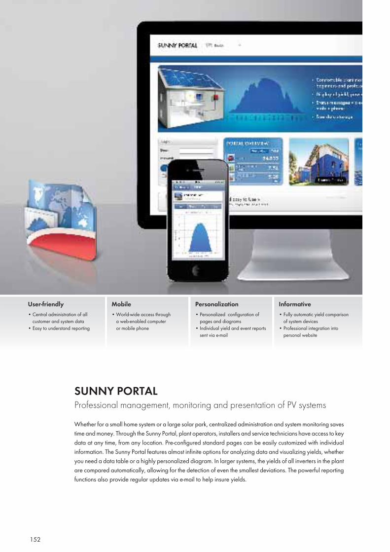
152
SUNNY PORTAL Professional management, monitoring and presentation of PV systemsWhether for a small home system or a large solar park, centralized administration and system monitoring saves time and money. Through the Sunny Portal, plant operators, installers and service technicians have access to key data at any time, from any location. Pre-configured standard pages can be easily customized with individual information. The Sunny Portal features almost infinite options for analyzing data and visualizing yields, whether you need a data table or a highly personalized diagram. In larger systems, the yields of all inverters in the plant are compared automatically, allowing for the detection of even the smallest deviations. The powerful reporting functions also provide regular updates via e-mail to help insure yields.
User-friendly• Central administration of all
customer and system data• Easy to understand reporting
Mobile • World-wide access through
a web-enabled computer or mobile phone
Personalization• Personalized configuration of
pages and diagrams• Individual yield and event reports
sent via e-mail
Informative• Fully automatic yield comparison
of system devices • Professional integration into
personal website
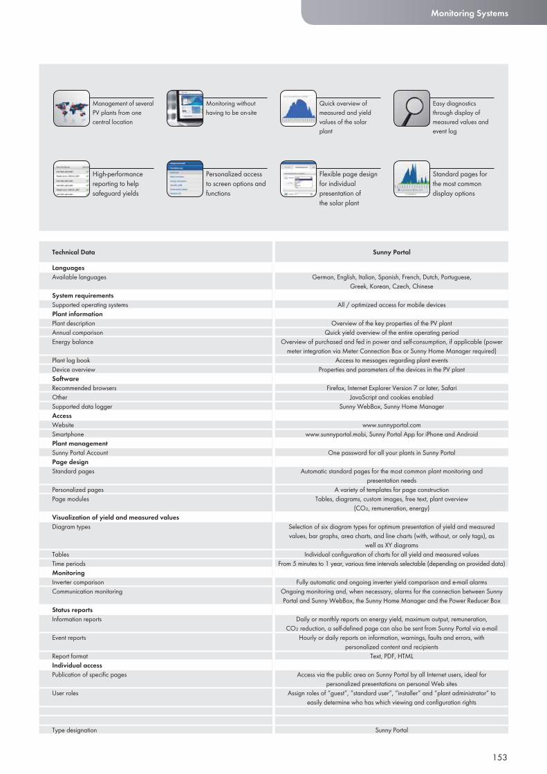
153
Monitoring Systems
LanguagesAvailable languages
System requirementsSupported operating systemsPlant informationPlant descriptionAnnual comparisonEnergy balance
Plant log bookDevice overviewSoftwareRecommended browsersOtherSupported data loggerAccessWebsiteSmartphonePlant managementSunny Portal AccountPage designStandard pages
Personalized pagesPage modules
Visualization of yield and measured valuesDiagram types
TablesTime periodsMonitoringInverter comparisonCommunication monitoring
Status reportsInformation reports
Event reports
Report formatIndividual accessPublication of specifi c pages
User roles
Type designation
Technical Data Sunny Portal
Monitoring without having to be on-site
Management of several PV plants from one central location
Personalized access to screen options and functions
Quick overview of measured and yield values of the solar plant
High-performance reporting to help safeguard yields
Easy diagnostics through display of measured values and event log
Flexible page design for individual presentation of the solar plant
Standard pages for the most common display options
German, English, Italian, Spanish, French, Dutch, Portuguese, Greek, Korean, Czech, Chinese
All / optimized access for mobile devices
Overview of the key properties of the PV plantQuick yield overview of the entire operating period
Overview of purchased and fed in power and self-consumption, if applicable (power meter integration via Meter Connection Box or Sunny Home Manager required)
Access to messages regarding plant eventsProperties and parameters of the devices in the PV plant
Firefox, Internet Explorer Version 7 or later, SafariJavaScript and cookies enabled
Sunny WebBox, Sunny Home Manager
www.sunnyportal.comwww.sunnyportal.mobi, Sunny Portal App for iPhone and Android
One password for all your plants in Sunny Portal
Automatic standard pages for the most common plant monitoring and presentation needs
A variety of templates for page constructionTables, diagrams, custom images, free text, plant overview
(CO₂, remuneration, energy)
Selection of six diagram types for optimum presentation of yield and measured values, bar graphs, area charts, and line charts (with, without, or only tags), as
well as XY diagramsIndividual confi guration of charts for all yield and measured values
From 5 minutes to 1 year, various time intervals selectable (depending on provided data)
Fully automatic and ongoing inverter yield comparison and e-mail alarmsOngoing monitoring and, when necessary, alarms for the connection between Sunny Portal and Sunny WebBox, the Sunny Home Manager and the Power Reducer Box
Daily or monthly reports on energy yield, maximum output, remuneration, CO₂ reduction, a self-defi ned page can also be sent from Sunny Portal via e-mail
Hourly or daily reports on information, warnings, faults and errors, with personalized content and recipients
Text, PDF, HTML
Access via the public area on Sunny Portal by all Internet users, ideal for personalized presentations on personal Web sites
Assign roles of “guest”, “standard user”, “installer” and “plant administrator” to easily determine who has which viewing and confi guration rights
Sunny Portal
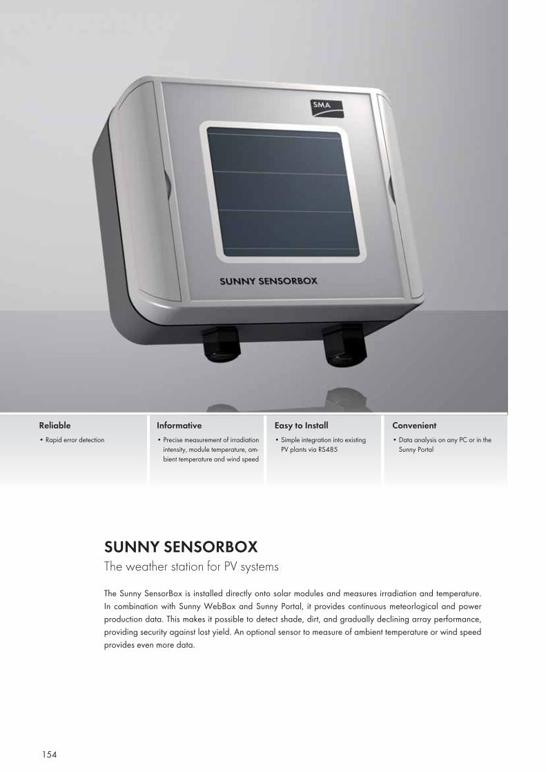
154
SUNNY SENSORBOX The weather station for PV systemsThe Sunny SensorBox is installed directly onto solar modules and measures irradiation and temperature. In combination with Sunny WebBox and Sunny Portal, it provides continuous meteorlogical and power production data. This makes it possible to detect shade, dirt, and gradually declining array performance, providing security against lost yield. An optional sensor to measure of ambient temperature or wind speed provides even more data.
Reliable• Rapid error detection
Informative• Precise measurement of irradiation
intensity, module temperature, am-bient temperature and wind speed
Easy to Install• Simple integration into existing
PV plants via RS485
Convenient • Data analysis on any PC or in the
Sunny Portal
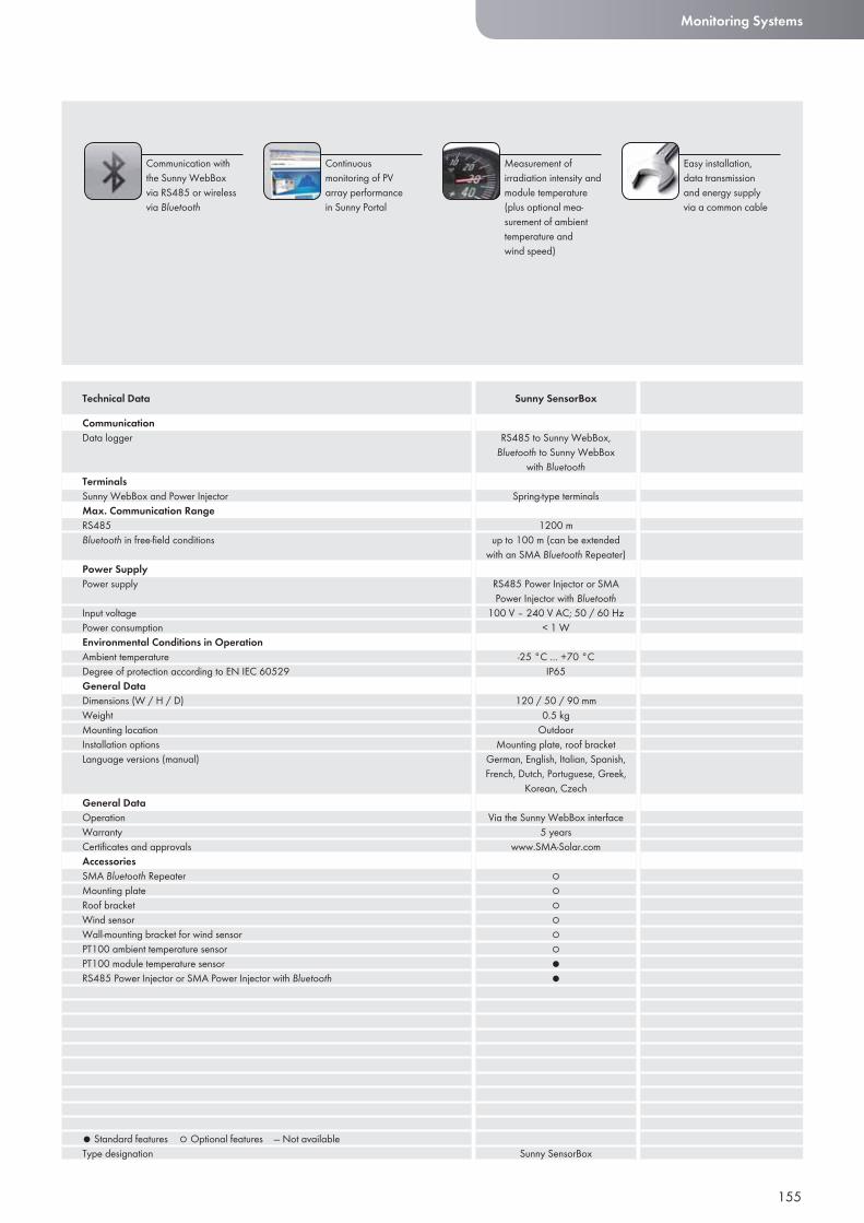
155
Monitoring Systems
CommunicationData logger
TerminalsSunny WebBox and Power InjectorMax. Communication RangeRS485Bluetooth in free-fi eld conditions
Power SupplyPower supply
Input voltagePower consumptionEnvironmental Conditions in OperationAmbient temperatureDegree of protection according to EN IEC 60529General DataDimensions (W / H / D)WeightMounting locationInstallation optionsLanguage versions (manual)
General DataOperationWarrantyCertifi cates and approvalsAccessoriesSMA Bluetooth RepeaterMounting plateRoof bracketWind sensorWall-mounting bracket for wind sensorPT100 ambient temperature sensorPT100 module temperature sensorRS485 Power Injector or SMA Power Injector with Bluetooth
● Standard features ○ Optional features — Not availableType designation
Technical Data Sunny SensorBox
Continuous monitoring of PV array performance in Sunny Portal
Communication with the Sunny WebBox via RS485 or wireless via Bluetooth
Measurement of irradiation intensity and module temperature (plus optional mea-surement of ambient temperature and wind speed)
Easy installation, data transmission and energy supply via a common cable
RS485 to Sunny WebBox, Bluetooth to Sunny WebBox
with Bluetooth
Spring-type terminals
1200 mup to 100 m (can be extended
with an SMA Bluetooth Repeater)
RS485 Power Injector or SMA Power Injector with Bluetooth
100 V – 240 V AC; 50 / 60 Hz< 1 W
-25 °C … +70 °CIP65
120 / 50 / 90 mm0.5 kg
OutdoorMounting plate, roof bracket
German, English, Italian, Spanish, French, Dutch, Portuguese, Greek,
Korean, Czech
Via the Sunny WebBox interface5 years
www.SMA-Solar.com
○○○○○○●●
Sunny SensorBox
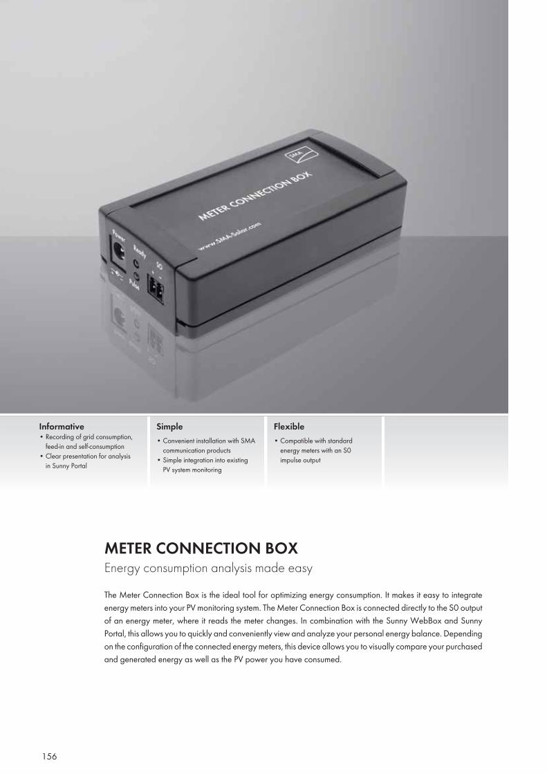
156
METER CONNECTION BOX Energy consumption analysis made easyThe Meter Connection Box is the ideal tool for optimizing energy consumption. It makes it easy to integrate energy meters into your PV monitoring system. The Meter Connection Box is connected directly to the S0 output of an energy meter, where it reads the meter changes. In combination with the Sunny WebBox and Sunny Portal, this allows you to quickly and conveniently view and analyze your personal energy balance. Depending on the confi guration of the connected energy meters, this device allows you to visually compare your purchased and generated energy as well as the PV power you have consumed.
Informative• Recording of grid consumption, feed-in and self-consumption• Clear presentation for analysis in Sunny Portal
Simple• Convenient installation with SMA communication products• Simple integration into existing PV system monitoring
Flexible• Compatible with standard energy meters with an S0 impulse output
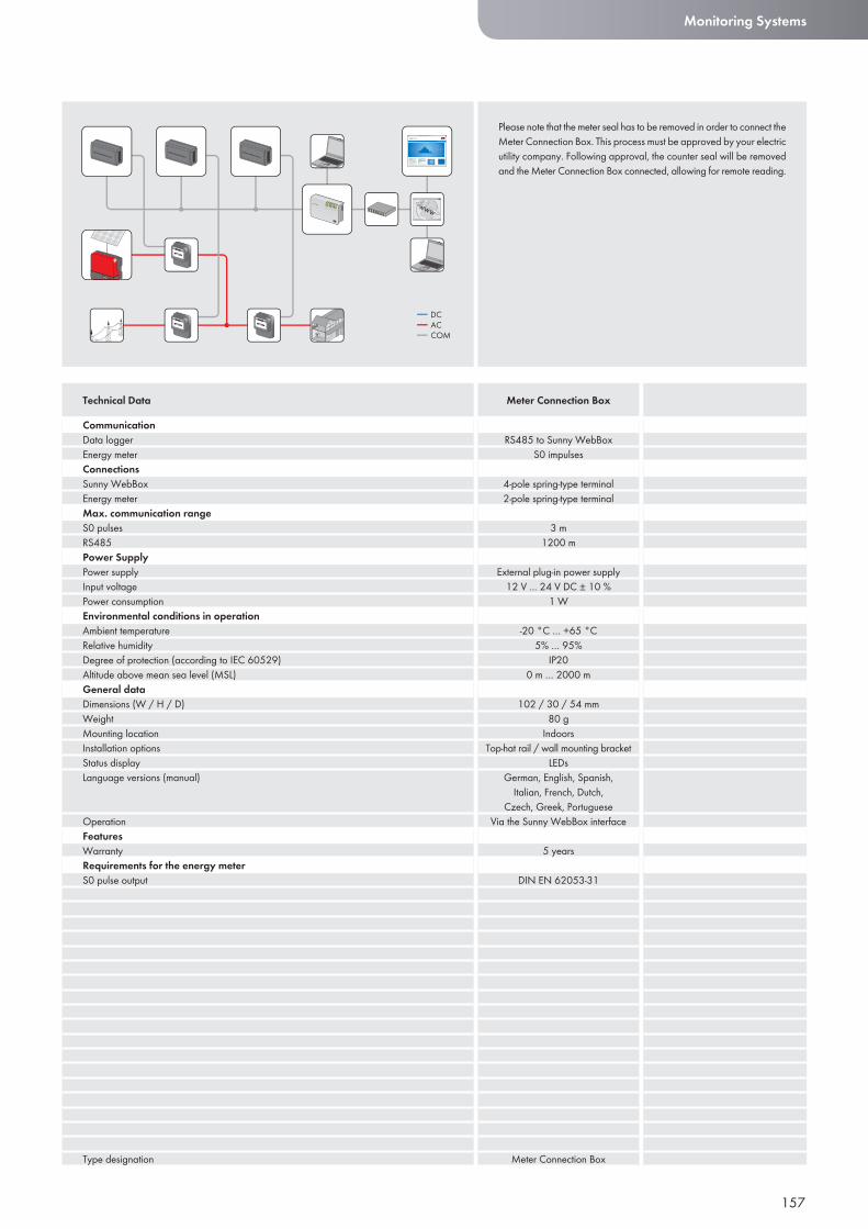
157
Monitoring Systems
CommunicationData loggerEnergy meterConnectionsSunny WebBoxEnergy meterMax. communication rangeS0 pulsesRS485Power SupplyPower supplyInput voltagePower consumptionEnvironmental conditions in operationAmbient temperatureRelative humidityDegree of protection (according to IEC 60529)Altitude above mean sea level (MSL) General dataDimensions (W / H / D)WeightMounting locationInstallation optionsStatus displayLanguage versions (manual)
OperationFeaturesWarrantyRequirements for the energy meterS0 pulse output
Type designation
Technical Data Meter Connection Box
Please note that the meter seal has to be removed in order to connect the Meter Connection Box. This process must be approved by your electric utility company. Following approval, the counter seal will be removed and the Meter Connection Box connected, allowing for remote reading.
RS485 to Sunny WebBoxS0 impulses
4-pole spring-type terminal2-pole spring-type terminal
3 m1200 m
External plug-in power supply12 V ... 24 V DC ± 10 %
1 W
-20 °C … +65 °C5% … 95%
IP200 m … 2000 m
102 / 30 / 54 mm 80 g
IndoorsTop-hat rail / wall mounting bracket
LEDsGerman, English, Spanish,
Italian, French, Dutch, Czech, Greek, Portuguese
Via the Sunny WebBox interface
5 years
DIN EN 62053-31
Meter Connection Box
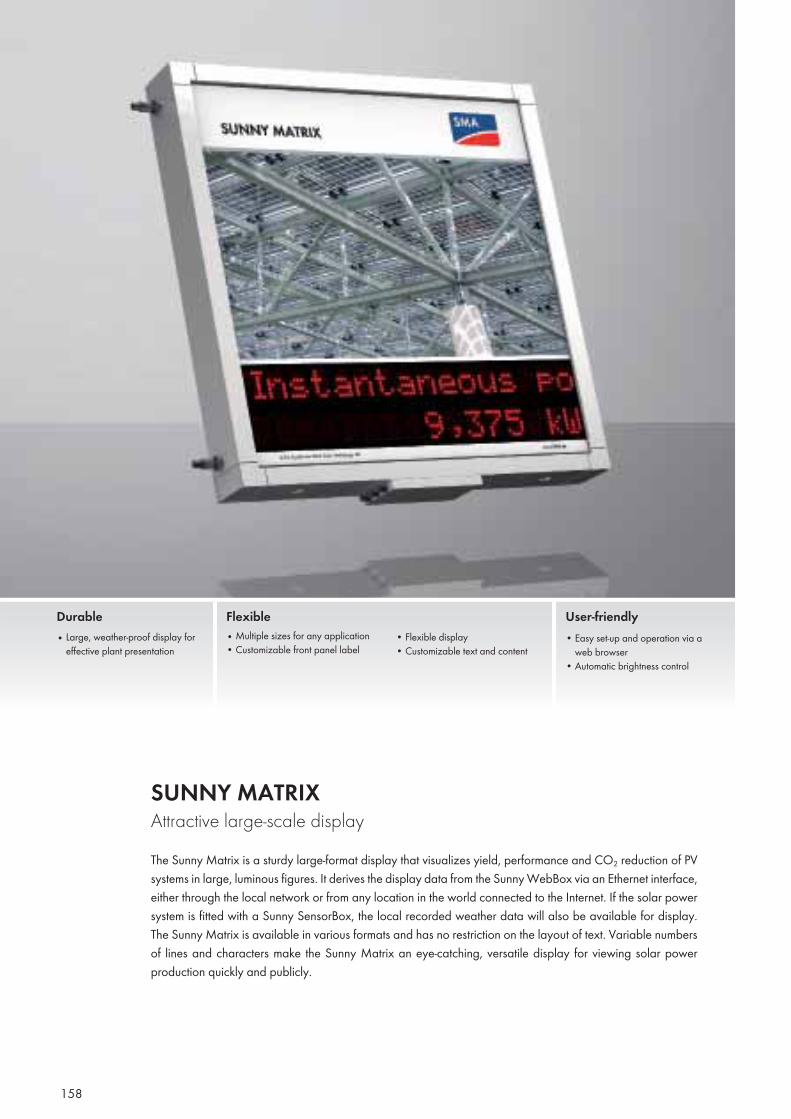
158
SUNNY MATRIX Attractive large-scale displayThe Sunny Matrix is a sturdy large-format display that visualizes yield, performance and CO2 reduction of PV systems in large, luminous figures. It derives the display data from the Sunny WebBox via an Ethernet interface, either through the local network or from any location in the world connected to the Internet. If the solar power system is fitted with a Sunny SensorBox, the local recorded weather data will also be available for display. The Sunny Matrix is available in various formats and has no restriction on the layout of text. Variable numbers of lines and characters make the Sunny Matrix an eye-catching, versatile display for viewing solar power production quickly and publicly.
Durable• Large, weather-proof display for
effective plant presentation
Flexible• Multiple sizes for any application• Customizable front panel label
• Flexible display• Customizable text and content
User-friendly• Easy set-up and operation via a
web browser • Automatic brightness control
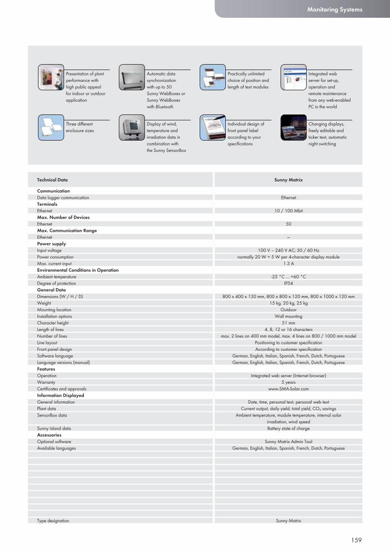
159
Monitoring Systems
CommunicationData logger communicationTerminalsEthernetMax. Number of DevicesEthernetMax. Communication RangeEthernetPower supplyInput voltagePower consumptionMax. current inputEnvironmental Conditions in OperationAmbient temperatureDegree of protectionGeneral DataDimensions (W / H / D)WeightMounting locationInstallation optionsCharacter heightLength of linesNumber of linesLine layoutFront panel designSoftware languageLanguage versions (manual)FeaturesOperationWarrantyCertifi cates and approvalsInformation DisplayedGeneral informationPlant dataSensorBox data
Sunny Island dataAccessoriesOptional softwareAvailable languages
Type designation
Technical Data Sunny Matrix
Automatic data synchronization with up to 50 Sunny WebBoxes or Sunny WebBoxes with Bluetooth
Presentation of plant performance with high public appeal for indoor or outdoor application
Display of wind, temperature and irradiation data in combination with the Sunny SensorBox
Practically unlimited choice of position and length of text modules
Three differentenclosure sizes
Integrated web server for set-up, operation and remote maintenance from any web-enabled PC in the world
Individual design of front panel label according to your specifi cations
Changing displays,freely editable and ticker text, automatic night switching
Ethernet
10 / 100 Mbit
50
—
100 V – 240 V AC; 50 / 60 Hznormally 20 W + 5 W per 4-character display module
1.3 A
-25 °C … +60 °CIP54
800 x 400 x 120 mm, 800 x 800 x 120 mm, 800 x 1000 x 120 mm15 kg, 20 kg, 25 kg
OutdoorWall mounting
51 mm4, 8, 12 or 16 characters
max. 2 lines on 400 mm model, max. 4 lines on 800 / 1000 mm modelPositioning to customer specifi cationAccording to customer specifi cation
German, English, Italian, Spanish, French, Dutch, PortugueseGerman, English, Italian, Spanish, French, Dutch, Portuguese
Integrated web server (Internet browser)5 years
www.SMA-Solar.com
Date, time, personal text, personal web textCurrent output, daily yield, total yield, CO2 savings
Ambient temperature, module temperature, internal solar irradiation, wind speedBattery state of charge
Sunny Matrix Admin ToolGerman, English, Italian, Spanish, French, Dutch, Portuguese
Sunny Matrix
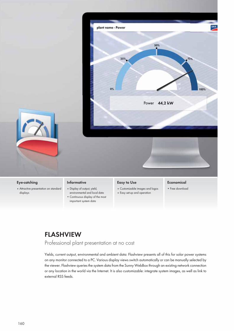
160
FLASHVIEW Professional plant presentation at no costYields, current output, environmental and ambient data: Flashview presents all of this for solar power systems on any monitor connected to a PC. Various display views switch automatically or can be manually selected by the viewer. Flashview queries the system data from the Sunny WebBox through an existing network connection or any location in the world via the Internet. It is also customizable: integrate system images, as well as link to external RSS feeds.
Eye-catching• Attractive presentation on standard
displays
Informative • Display of output, yield,
environmental and local data• Continuous display of the most
important system data
Easy to Use• Customizable images and logos• Easy set-up and operation
Economical• Free download
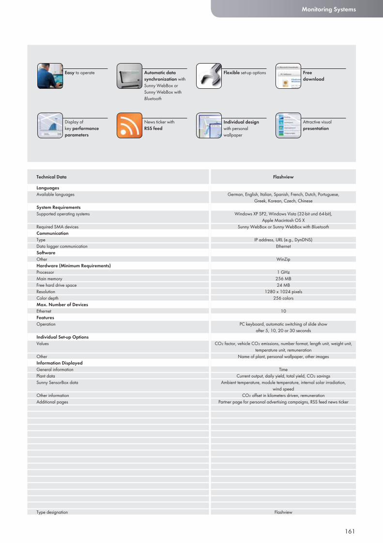
161
Monitoring Systems
LanguagesAvailable languages
System RequirementsSupported operating systems
Required SMA devicesCommunicationTypeData logger communicationSoftwareOtherHardware (Minimum Requirements) ProcessorMain memoryFree hard drive spaceResolutionColor depthMax. Number of DevicesEthernetFeaturesOperation
Individual Set-up OptionsValues
OtherInformation DisplayedGeneral informationPlant dataSunny SensorBox data
Other informationAdditional pages
Type designation
Technical Data Flashview
Automatic data synchronization with Sunny WebBox or Sunny WebBox with Bluetooth
Easy to operate
News ticker with RSS feed
Flexible set-up options
Display ofkey performance parameters
Freedownload
Individual design with personal wallpaper
Attractive visual presentation
German, English, Italian, Spanish, French, Dutch, Portuguese, Greek, Korean, Czech, Chinese
Windows XP SP2, Windows Vista (32-bit und 64-bit), Apple Macintosh OS X
Sunny WebBox or Sunny WebBox with Bluetooth
IP address, URL (e.g., DynDNS)Ethernet
WinZip
1 GHz256 MB24 MB
1280 x 1024 pixels256 colors
10
PC keyboard, automatic switching of slide show after 5, 10, 20 or 30 seconds
CO₂ factor, vehicle CO₂ emissions, number format, length unit, weight unit, temperature unit, remuneration
Name of plant, personal wallpaper, other images
TimeCurrent output, daily yield, total yield, CO₂ savings
Ambient temperature, module temperature, internal solar irradiation, wind speed
CO₂ offset in kilometers driven, remunerationPartner page for personal advertising campaigns, RSS feed news ticker
Flashview
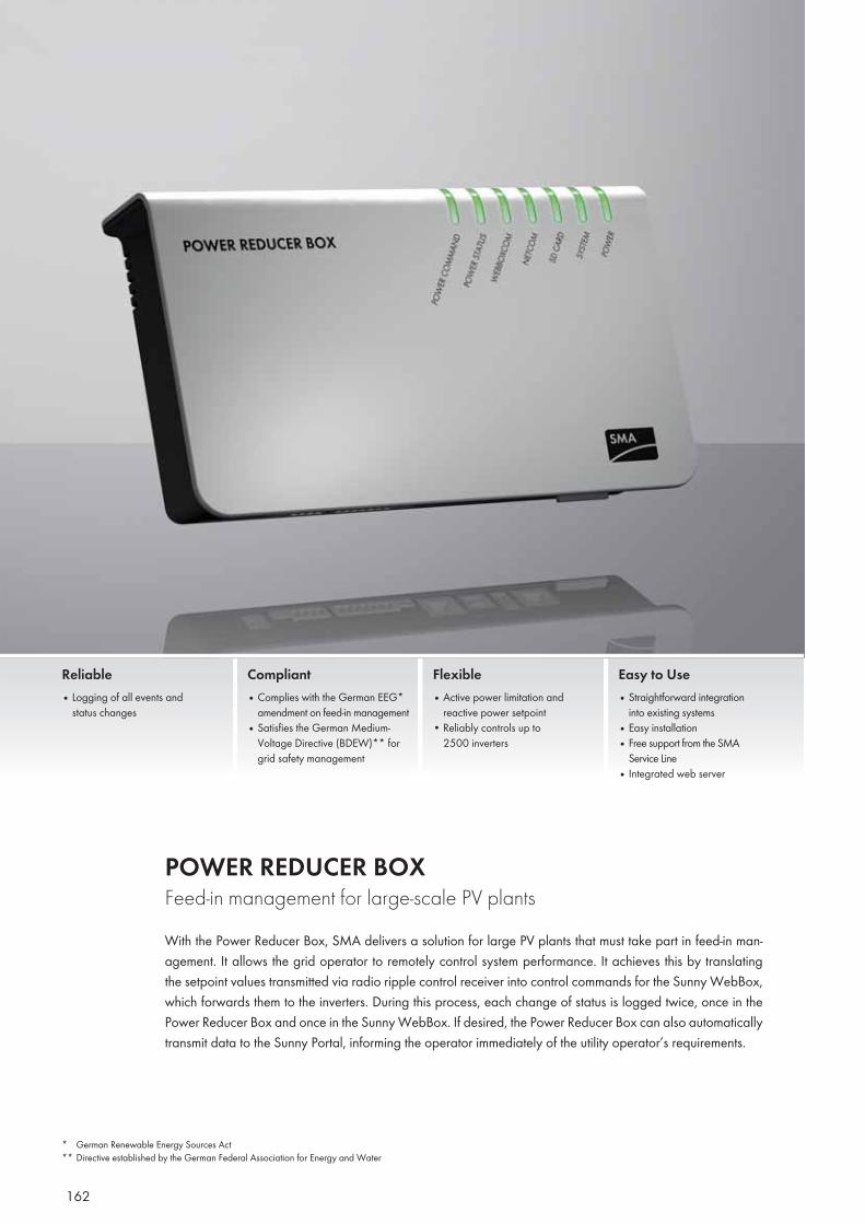
162
POWER REDUCER BOX Feed-in management for large-scale PV plantsWith the Power Reducer Box, SMA delivers a solution for large PV plants that must take part in feed-in man-agement. It allows the grid operator to remotely control system performance. It achieves this by translating the setpoint values transmitted via radio ripple control receiver into control commands for the Sunny WebBox, which forwards them to the inverters. During this process, each change of status is logged twice, once in the Power Reducer Box and once in the Sunny WebBox. If desired, the Power Reducer Box can also automatically transmit data to the Sunny Portal, informing the operator immediately of the utility operator’s requirements.
Reliable• Logging of all events and
status changes
Compliant• Complies with the German EEG*
amendment on feed-in management• Satisfies the German Medium-
Voltage Directive (BDEW)** for grid safety management
Flexible• Active power limitation and
reactive power setpoint• Reliably controls up to
2500 inverters
Easy to Use• Straightforward integration
into existing systems • Easy installation• Free support from the SMA
Service Line• Integrated web server
* German Renewable Energy Sources Act** Directive established by the German Federal Association for Energy and Water
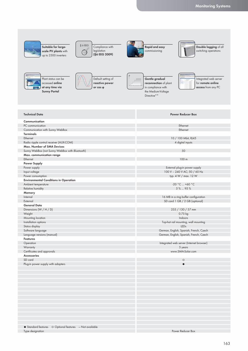
§ 6 EEG
163
Monitoring Systems
CommunicationPC communicationCommunication with Sunny WebBoxTerminalsEthernetRadio ripple control receiver (AUX-COM)Max. Number of SMA DevicesSunny WebBox (not Sunny WebBox with Bluetooth)Max. communication rangeEthernetPower SupplyPower supplyInput voltagePower consumptionEnvironmental Conditions in OperationAmbient temperatureRelative humidityMemoryInternalExternalGeneral DataDimensions (W / H / D)WeightMounting locationInstallation optionsStatus displaySoftware languageLanguage versions (manual)FeaturesOperationWarrantyCertifi cates and approvalsAccessoriesSD cardPlug-in power supply with adapters
● Standard features ○ Optional features — Not availableType designation
Technical Data Power Reducer Box
Compliance with legislation(§6 EEG 2009)
Suitable for large-scale PV plants with up to 2500 inverters
Default setting of reactive poweror cos ϕ
Rapid and easy commissioning
Plant status can be accessed online at any time via Sunny Portal
Double logging of all switching operations
Gentle gradualreconnection of plant in compliance with the Medium-Voltage Directive**
Integrated web server for remote online access from any PC
EthernetEthernet
10 / 100 Mbit, RJ454 digital inputs
50
100 m
External plug-in power supply100 V – 240 V AC; 50 / 60 Hz
typ. 4 W / max. 12 W
-20 °C … +60 °C5 % … 95 %
16 MB in a ring buffer confi gurationSD card 1 GB / 2 GB (optional)
255 / 130 / 57 mm0.75 kgIndoors
Top-hat rail mounting, wall mountingLEDs
German, English, Spanish, French, CzechGerman, English, Spanish, French, Czech
Integrated web server (Internet browser)5 years
www.SMA-Solar.com
○●
Power Reducer Box
164
SMA OPC SERVER The standardized data interface for large-scale systemsLarge-scale plants and PV power utility stations require customized monitoring solutions and need to link sys-tems and components supplied by different manufacturers into one joint control system. OPC, the international communication standard in the field of automation technology, enables simple and reliable data exchange between products and applications supplied by different vendors. With the SMA OPC Server, SMA equipment can be very easily integrated into OPC-compatible systems.
Professional• Visualization, control and monitor-
ing of large-scale plants• Integration of SMA equipment into
existing control-room technology such as GLT and SCADA systems
Innovative• One data interface for up to
2500 SMA devices• Data interface in accordance
with the OPC-DA/OPC-XML-DA communication standard
Simple• One data interface for
50 Sunny WebBox devices, even at different locations
• Compatible with WinCC, InTouch, WEBfactory, etc.
Flexible• Simple and fast installation,
high reliability• Compatible with WinCC, InTouch,
LabView, etc.
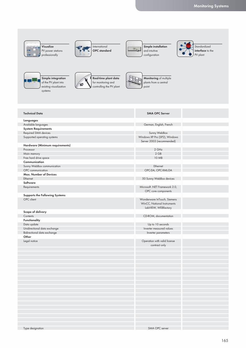
165
Monitoring Systems
LanguagesAvailable languagesSystem RequirementsRequired SMA devicesSupported operating systems
Hardware (Minimum requirements)ProcessorMain memoryFree hard drive spaceCommunicationSunny WebBox communicationOPC communicationMax. Number of DevicesEthernetSoftwareRequirements
Supports the Following SystemsOPC client
Scope of deliveryContentsFunctionalityData updateUnidirectional data exchangeBidirectional data exchangeOtherLegal notice
Type designation
Technical Data SMA OPC Server
International OPC standard
VisualizePV power stations professionally
Real-time plant data for monitoring and controlling the PV plant
Simple installation and intuitive configuration
Simple integration of the PV plant into existing visualization systems
Standardized interface to the PV plant
Monitoring of multiple plants from a central point
German, English, French
Sunny WebBoxWindows XP Pro (SP2), Windows
Server 2003 (recommended)
2 GHz2 GB
10 MB
EthernetOPC-DA, OPC-XML-DA
50 Sunny WebBox devices
Microsoft .NET Framework 2.0, OPC core components
Wonderware InTouch, Siemens WinCC, National Instruments
LabVIEW, WEBfactory
CD-ROM, documentation
Up to 10 secondsInverter measured values
Inverter parameters
Operation with valid license contract only
SMA OPC server
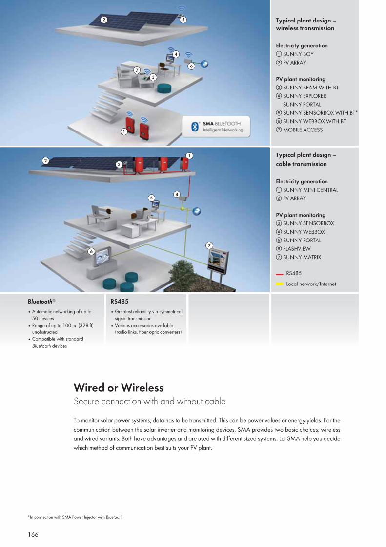
166
Typical plant design – wireless transmission
Electricity generation① SUNNY BOY② PV ARRAY
PV plant monitoring③ SUNNY BEAM WITH BT④ SUNNY EXPLORER SUNNY PORTAL⑤ SUNNY SENSORBOX WITH BT*⑥ SUNNY WEBBOX WITH BT⑦ MOBILE ACCESS
Typical plant design –cable transmission
Electricity generation① SUNNY MINI CENTRAL② PV ARRAY
PV plant monitoring③ SUNNY SENSORBOX ④ SUNNY WEBBOX⑤ SUNNY PORTAL⑥ FLASHVIEW⑦ SUNNY MATRIX
RS485 Local network/Internet
Wired or WirelessSecure connection with and without cableTo monitor solar power systems, data has to be transmitted. This can be power values or energy yields. For the communication between the solar inverter and monitoring devices, SMA provides two basic choices: wireless and wired variants. Both have advantages and are used with different sized systems. Let SMA help you decide which method of communication best suits your PV plant.
Bluetooth®
• Automatic networking of up to50 devices
• Range of up to 100 m (328 ft)unobstructed
• Compatible with standard Bluetooth devices
RS485• Greatest reliability via symmetrical
signal transmission• Various accessories available
(radio links, fiber optic converters)
2
37
4
1
2
4
6
6
7
5
5
13
*In connection with SMA Power Injector with Bluetooth
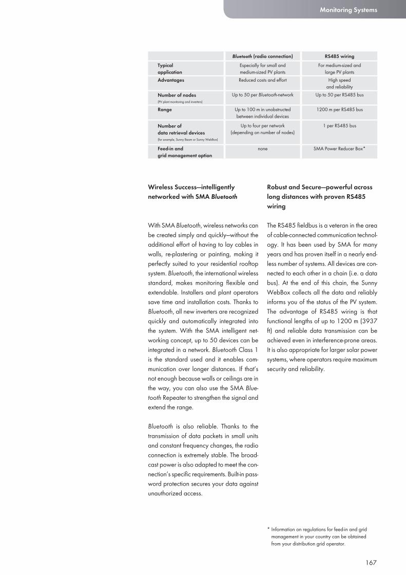
167
Wireless Success—intelligently networked with SMA Bluetooth
With SMA Bluetooth, wireless networks can be created simply and quickly—without the additional effort of having to lay cables in walls, re-plastering or painting, making it perfectly suited to your residential rooftop system. Bluetooth, the international wireless standard, makes monitoring flexible and extendable. Installers and plant operators save time and installation costs. Thanks to Bluetooth, all new inverters are recognized quickly and automatically integrated into the system. With the SMA intelligent net-working concept, up to 50 devices can be integrated in a network. Bluetooth Class 1 is the standard used and it enables com-munication over longer distances. If that’s not enough because walls or ceilings are in the way, you can also use the SMA Blue-tooth Repeater to strengthen the signal and extend the range.
Bluetooth is also reliable. Thanks to the transmission of data packets in small units and constant frequency changes, the radio connection is extremely stable. The broad-cast power is also adapted to meet the con-nection’s specific requirements. Built-in pass-word protection secures your data against unauthorized access.
Robust and Secure—powerful across long distances with proven RS485 wiring
The RS485 fieldbus is a veteran in the area of cable-connected communication technol-ogy. It has been used by SMA for many years and has proven itself in a nearly end-less number of systems. All devices are con-nected to each other in a chain (i.e. a data bus). At the end of this chain, the Sunny WebBox collects all the data and reliably informs you of the status of the PV system. The advantage of RS485 wiring is that functional lengths of up to 1200 m (3937 ft) and reliable data transmission can be achieved even in interference-prone areas. It is also appropriate for larger solar power systems, where operators require maximum security and reliability.
Monitoring Systems
Bluetooth (radio connection) RS485 wiring Typicalapplication
Especially for small and medium-sized PV plants
For medium-sized and large PV plants
Advantages Reduced costs and effort High speedand reliability
Number of nodes (PV plant monitoring and inverters)
Up to 50 per Bluetooth-network
Up to 50 per RS485 bus
Range Up to 100 m in unobstructedbetween individual devices
1200 m per RS485 bus
Number of data retrieval devices (for example, Sunny Beam or Sunny WebBox)
Up to four per network (depending on number of nodes)
1 per RS485 bus
Feed-in and grid management option
none SMA Power Reducer Box*
* Information on regulations for feed-in and grid management in your country can be obtained from your distribution grid operator.
OFF-GRID INVERTERS
168
169

170
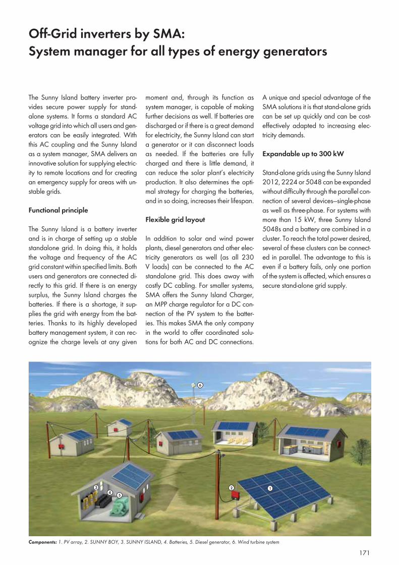
Off-Grid inverters by SMA:System manager for all types of energy generators
moment and, through its function as system manager, is capable of making further decisions as well. If batteries are discharged or if there is a great demand for electricity, the Sunny Island can start a generator or it can disconnect loads as needed. If the batteries are fully charged and there is little demand, it can reduce the solar plant’s electricity production. It also determines the opti-mal strategy for charging the batteries, and in so doing, increases their lifespan.
Flexible grid layout
In addition to solar and wind power plants, diesel generators and other elec-tricity generators as well (as all 230 V loads) can be connected to the AC standalone grid. This does away with costly DC cabling. For smaller systems, SMA offers the Sunny Island Charger, an MPP charge regulator for a DC con-nection of the PV system to the batter-ies. This makes SMA the only company in the world to offer coordinated solu-tions for both AC and DC connections.
The Sunny Island battery inverter pro-vides secure power supply for stand-alone systems. It forms a standard AC voltage grid into which all users and gen-erators can be easily integrated. With this AC coupling and the Sunny Island as a system manager, SMA delivers an innovative solution for supplying electric-ity to remote locations and for creating an emergency supply for areas with un-stable grids.
Functional principle
The Sunny Island is a battery inverter and is in charge of setting up a stable standalone grid. In doing this, it holds the voltage and frequency of the AC grid constant within specified limits. Both users and generators are connected di-rectly to this grid. If there is an energy surplus, the Sunny Island charges the batteries. If there is a shortage, it sup-plies the grid with energy from the bat-teries. Thanks to its highly developed battery management system, it can rec-ognize the charge levels at any given
Components: 1. PV array, 2. SUNNY BOY, 3. SUNNY ISLAND, 4. Batteries, 5. Diesel generator, 6. Wind turbine system
6
Einführung Wechselrichtertechnik
A unique and special advantage of the SMA solutions it is that stand-alone grids can be set up quickly and can be cost-effectively adapted to increasing elec-tricity demands.
Expandable up to 300 kW
Stand-alone grids using the Sunny Island 2012, 2224 or 5048 can be expanded without difficulty through the parallel con-nection of several devices—single-phase as well as three-phase. For systems with more than 15 kW, three Sunny Island 5048s and a battery are combined in a cluster. To reach the total power desired, several of these clusters can be connect-ed in parallel. The advantage to this is even if a battery fails, only one portion of the system is affected, which ensures a secure stand-alone grid supply.
171
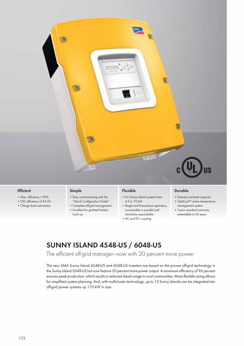
172
SUNNY ISLAND 4548-US / 6048-US The efficient off-grid manager—now with 20 percent more powerThe new SMA Sunny Island 4548-US and 6048-US inverters are based on the proven off-grid technology in the Sunny Island 5048-US but now feature 20 percent more power output. A maximum efficiency of 96 percent ensures peak production, which results in reduced diesel usage in rural communities. More flexible sizing allows for simplified system planning. And, with multicluster technology, up to 12 Sunny Islands can be integrated into off-grid power systems up 110 kW in size.
Efficient • Max. efficiency > 96%• CEC efficiency of 94.5%• Charge level calculation
Simple • Easy commissioning with the
“Quick Configuration Guide”• Complete off-grid management• Excellent for grid-tied battery back up
Flexible• For Sunny Island systems from 4.5 to 72 kW• Single and three-phase operation, connectable in parallel and modularly expandable• AC and DC coupling
Durable• Extreme overload capacity• OptiCool™ active temperature management system• 5-year standard warranty, extendable to 20 years
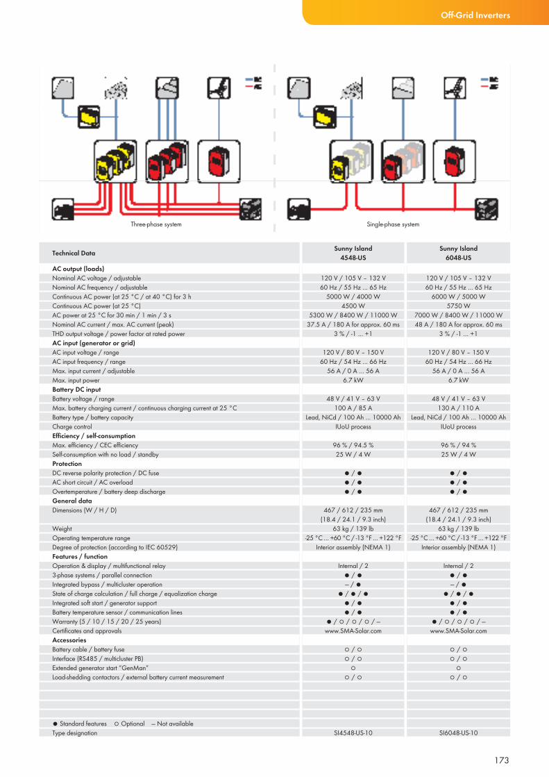
Three-phase system Single-phase system
173
Off-Grid Inverters
AC output (loads)Nominal AC voltage / adjustableNominal AC frequency / adjustableContinuous AC power (at 25 °C / at 40 °C) for 3 hContinuous AC power (at 25 °C)AC power at 25 °C for 30 min / 1 min / 3 sNominal AC current / max. AC current (peak)THD output voltage / power factor at rated powerAC input (generator or grid)AC input voltage / rangeAC input frequency / rangeMax. input current / adjustableMax. input powerBattery DC inputBattery voltage / rangeMax. battery charging current / continuous charging current at 25 °CBattery type / battery capacityCharge controlEffi ciency / self-consumption Max. effi ciency / CEC effi ciencySelf-consumption with no load / standbyProtectionDC reverse polarity protection / DC fuseAC short circuit / AC overloadOvertemperature / battery deep dischargeGeneral dataDimensions (W / H / D)
WeightOperating temperature rangeDegree of protection (according to IEC 60529)Features / functionOperation & display / multifunctional relay3-phase systems / parallel connectionIntegrated bypass / multicluster operationState of charge calculation / full charge / equalization chargeIntegrated soft start / generator supportBattery temperature sensor / communication linesWarranty (5 / 10 / 15 / 20 / 25 years)Certifi cates and approvalsAccessoriesBattery cable / battery fuseInterface (RS485 / multicluster PB)Extended generator start “GenMan”Load-shedding contactors / external battery current measurement
● Standard features ○ Optional — Not availableType designation
120 V / 105 V – 132 V60 Hz / 55 Hz … 65 Hz
5000 W / 4000 W4500 W
5300 W / 8400 W / 11000 W37.5 A / 180 A for approx. 60 ms
3 % / -1 … +1
120 V / 80 V – 150 V60 Hz / 54 Hz … 66 Hz
56 A / 0 A … 56 A6.7 kW
48 V / 41 V – 63 V100 A / 85 A
Lead, NiCd / 100 Ah … 10000 AhIUoU process
96 % / 94.5 %25 W / 4 W
● / ●● / ●● / ●
467 / 612 / 235 mm(18.4 / 24.1 / 9.3 inch)
63 kg / 139 lb-25 °C … +60 °C / -13 °F … +122 °F
Interior assembly (NEMA 1)
Internal / 2● / ●— / ●
● / ● / ●● / ●● / ●
● / ○ / ○ / ○ / —www.SMA-Solar.com
○ / ○ ○ / ○
○○ / ○
SI4548-US-10
120 V / 105 V – 132 V60 Hz / 55 Hz … 65 Hz
6000 W / 5000 W5750 W
7000 W / 8400 W / 11000 W48 A / 180 A for approx. 60 ms
3 % / -1 … +1
120 V / 80 V – 150 V60 Hz / 54 Hz … 66 Hz
56 A / 0 A … 56 A6.7 kW
48 V / 41 V – 63 V130 A / 110 A
Lead, NiCd / 100 Ah … 10000 AhIUoU process
96 % / 94 %25 W / 4 W
● / ●● / ●● / ●
467 / 612 / 235 mm(18.4 / 24.1 / 9.3 inch)
63 kg / 139 lb-25 °C … +60 °C / -13 °F … +122 °F
Interior assembly (NEMA 1)
Internal / 2● / ●— / ●
● / ● / ●● / ●● / ●
● / ○ / ○ / ○ / —www.SMA-Solar.com
○ / ○ ○ / ○
○○ / ○
SI6048-US-10
Technical Data Sunny Island4548-US
Sunny Island6048-US
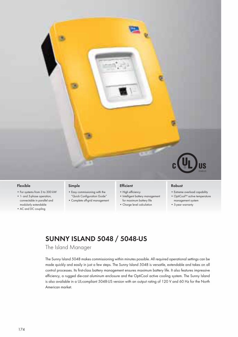
174
SUNNY ISLAND 5048 / 5048-USThe Island ManagerThe Sunny Island 5048 makes commissioning within minutes possible. All required operational settings can be made quickly and easily in just a few steps. The Sunny Island 5048 is versatile, extendable and takes on all control processes. Its first-class battery management ensures maximum battery life. It also features impressive efficiency, a rugged die-cast aluminum enclosure and the OptiCool active cooling system. The Sunny Island is also available in a UL-compliant 5048-US version with an output rating of 120 V and 60 Hz for the North American market.
Flexible • For systems from 3 to 300 kW • 1- and 3-phase operation,
connectable in parallel and modularly extendable
• AC and DC coupling
Simple • Easy commissioning with the
“Quick Configuration Guide”• Complete off-grid management
Efficient • High efficiency• Intelligent battery management
for maximum battery life• Charge level calculation
Robust • Extreme overload capability• OptiCool™ active temperature
management system• 5-year warranty
5048-US
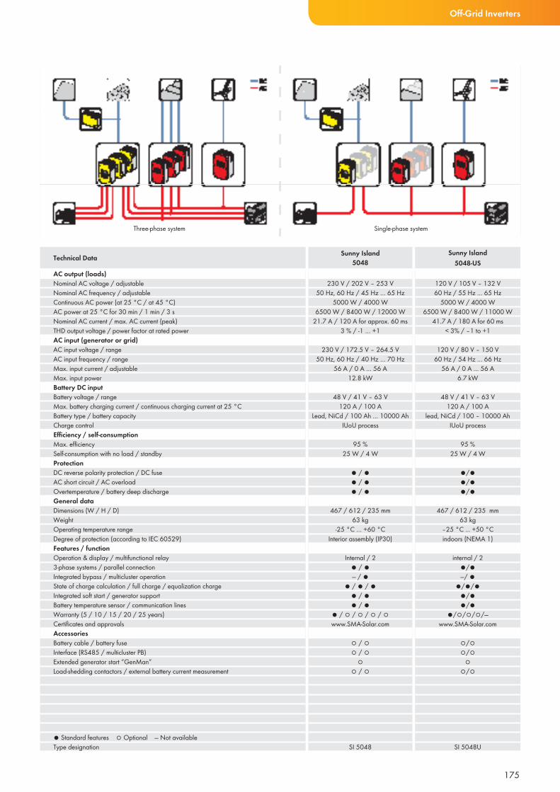
Three-phase system Single-phase system
175
Off-Grid Inverters
AC output (loads)Nominal AC voltage / adjustableNominal AC frequency / adjustableContinuous AC power (at 25 °C / at 45 °C)AC power at 25 °C for 30 min / 1 min / 3 sNominal AC current / max. AC current (peak)THD output voltage / power factor at rated powerAC input (generator or grid)AC input voltage / rangeAC input frequency / rangeMax. input current / adjustableMax. input powerBattery DC inputBattery voltage / rangeMax. battery charging current / continuous charging current at 25 °CBattery type / battery capacityCharge controlEffi ciency / self-consumption Max. effi ciencySelf-consumption with no load / standbyProtectionDC reverse polarity protection / DC fuseAC short circuit / AC overloadOvertemperature / battery deep dischargeGeneral dataDimensions (W / H / D)WeightOperating temperature rangeDegree of protection (according to IEC 60529)Features / functionOperation & display / multifunctional relay3-phase systems / parallel connectionIntegrated bypass / multicluster operationState of charge calculation / full charge / equalization chargeIntegrated soft start / generator supportBattery temperature sensor / communication linesWarranty (5 / 10 / 15 / 20 / 25 years)Certifi cates and approvalsAccessoriesBattery cable / battery fuseInterface (RS485 / multicluster PB)Extended generator start “GenMan”Load-shedding contactors / external battery current measurement
● Standard features ○ Optional — Not availableType designation
230 V / 202 V – 253 V50 Hz, 60 Hz / 45 Hz … 65 Hz
5000 W / 4000 W6500 W / 8400 W / 12000 W
21.7 A / 120 A for approx. 60 ms 3 % / -1 … +1
230 V / 172.5 V – 264.5 V50 Hz, 60 Hz / 40 Hz … 70 Hz
56 A / 0 A … 56 A12.8 kW
48 V / 41 V – 63 V120 A / 100 A
Lead, NiCd / 100 Ah … 10000 AhIUoU process
95 %
25 W / 4 W
● / ●● / ●● / ●
467 / 612 / 235 mm63 kg
-25 °C … +60 °CInterior assembly (IP30)
Internal / 2● / ●— / ●
● / ● / ●● / ●● / ●
● / ○ / ○ / ○ / ○www.SMA-Solar.com
○ / ○ ○ / ○
○○ / ○
SI 5048
120 V / 105 V – 132 V60 Hz / 55 Hz … 65 Hz
5000 W / 4000 W6500 W / 8400 W / 11000 W
41.7 A / 180 A for 60 ms< 3% / –1 to +1
120 V / 80 V – 150 V60 Hz / 54 Hz … 66 Hz
56 A / 0 A … 56 A6.7 kW
48 V / 41 V – 63 V120 A / 100 A
lead, NiCd / 100 – 10000 AhIUoU process
95 %25 W / 4 W
●/●●/●●/●
467 / 612 / 235 mm63 kg
–25 °C ... +50 °Cindoors (NEMA 1)
internal / 2●/● —/ ●
●/●/●●/●●/●
●/○/○/○/—www.SMA-Solar.com
○/○○/○
○○/○
SI 5048U
Technical Data Sunny Island5048
Sunny Island5048-US
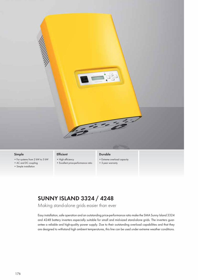
176
SUNNY ISLAND 3324 / 4248 Making stand-alone grids easier than everEasy installation, safe operation and an outstanding price-performance ratio make the SMA Sunny Island 3324 and 4248 battery inverters especially suitable for small and mid-sized stand-alone grids. The inverters guar-antee a reliable and high-quality power supply. Due to their outstanding overload capabilities and that they are designed to withstand high ambient temperatures, this line can be used under extreme weather conditions.
Simple• For systems from 2 kW to 5 kW• AC and DC coupling• Simple installation
Efficient• High efficiency• Excellent price-performance ratio
Durable• Extreme overload capacity• 5-year warranty
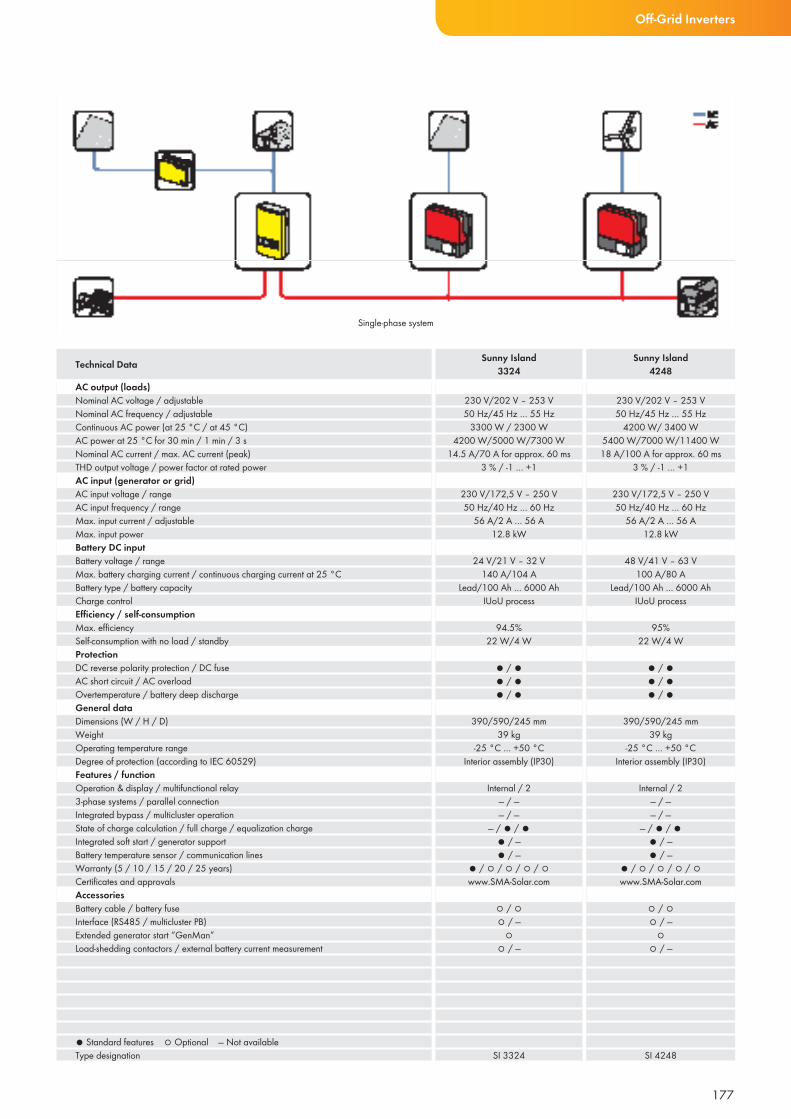
Single-phase system
177
AC output (loads)Nominal AC voltage / adjustableNominal AC frequency / adjustableContinuous AC power (at 25 °C / at 45 °C)AC power at 25 °C for 30 min / 1 min / 3 sNominal AC current / max. AC current (peak)THD output voltage / power factor at rated powerAC input (generator or grid)AC input voltage / rangeAC input frequency / rangeMax. input current / adjustableMax. input powerBattery DC inputBattery voltage / rangeMax. battery charging current / continuous charging current at 25 °CBattery type / battery capacityCharge controlEffi ciency / self-consumption Max. effi ciencySelf-consumption with no load / standbyProtectionDC reverse polarity protection / DC fuseAC short circuit / AC overloadOvertemperature / battery deep dischargeGeneral dataDimensions (W / H / D)WeightOperating temperature rangeDegree of protection (according to IEC 60529)Features / functionOperation & display / multifunctional relay3-phase systems / parallel connectionIntegrated bypass / multicluster operationState of charge calculation / full charge / equalization chargeIntegrated soft start / generator supportBattery temperature sensor / communication linesWarranty (5 / 10 / 15 / 20 / 25 years)Certifi cates and approvalsAccessoriesBattery cable / battery fuseInterface (RS485 / multicluster PB)Extended generator start “GenMan”Load-shedding contactors / external battery current measurement
● Standard features ○ Optional — Not availableType designation
230 V/202 V – 253 V50 Hz/45 Hz … 55 Hz
3300 W / 2300 W4200 W/5000 W/7300 W
14.5 A/70 A for approx. 60 ms 3 % / -1 … +1
230 V/172,5 V – 250 V50 Hz/40 Hz … 60 Hz
56 A/2 A … 56 A12.8 kW
24 V/21 V – 32 V140 A/104 A
Lead/100 Ah … 6000 AhIUoU process
94.5%
22 W/4 W
● / ●● / ●● / ●
390/590/245 mm39 kg
-25 °C … +50 °CInterior assembly (IP30)
Internal / 2— / —— / —
— / ● / ●● / —● / —
● / ○ / ○ / ○ / ○www.SMA-Solar.com
○ / ○ ○ / —
○○ / —
SI 3324
230 V/202 V – 253 V50 Hz/45 Hz … 55 Hz
4200 W/ 3400 W5400 W/7000 W/11400 W18 A/100 A for approx. 60 ms
3 % / -1 … +1
230 V/172,5 V – 250 V50 Hz/40 Hz … 60 Hz
56 A/2 A … 56 A12.8 kW
48 V/41 V – 63 V100 A/80 A
Lead/100 Ah … 6000 AhIUoU process
95%
22 W/4 W
● / ●● / ●● / ●
390/590/245 mm39 kg
-25 °C … +50 °CInterior assembly (IP30)
Internal / 2— / —— / —
— / ● / ●● / —● / —
● / ○ / ○ / ○ / ○www.SMA-Solar.com
○ / ○ ○ / —
○○ / —
SI 4248
Technical Data Sunny Island3324
Sunny Island4248
Off-Grid Inverters
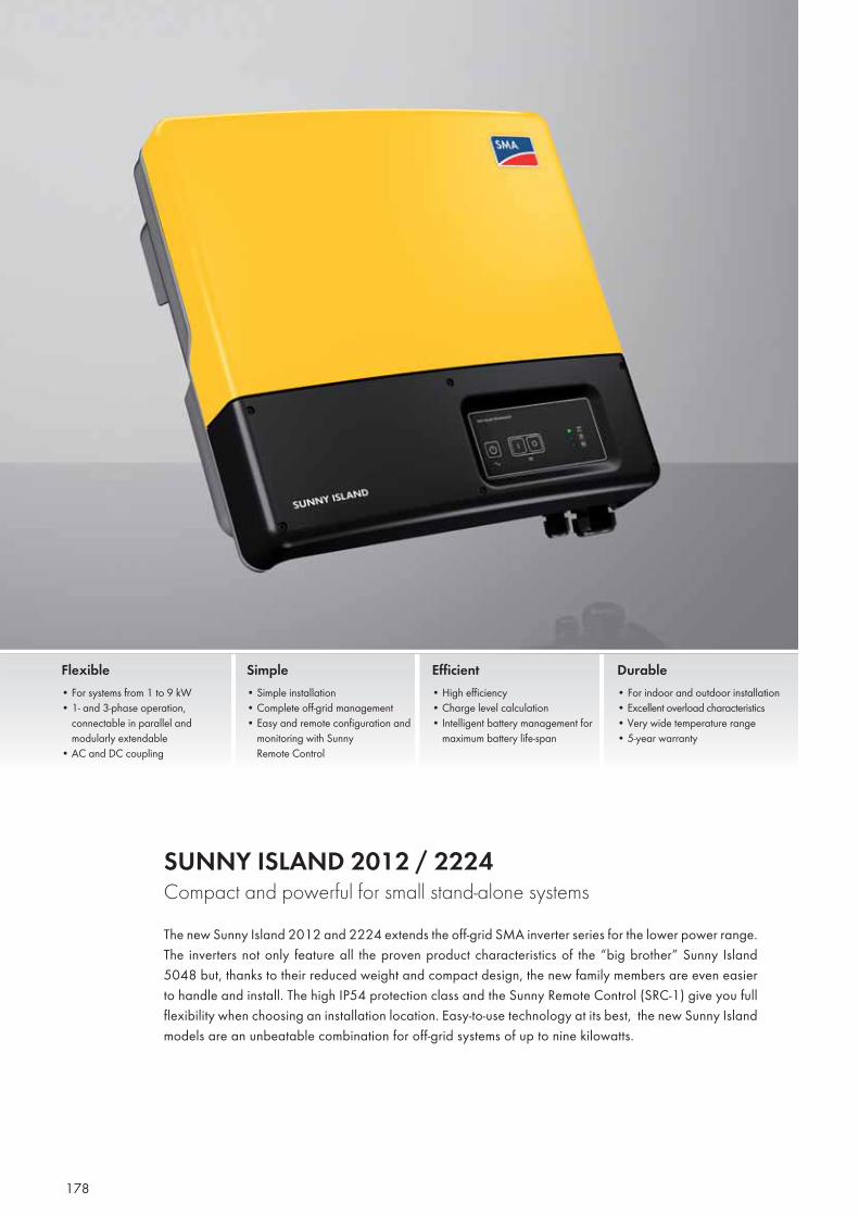
178
SUNNY ISLAND 2012 / 2224 Compact and powerful for small stand-alone systemsThe new Sunny Island 2012 and 2224 extends the off-grid SMA inverter series for the lower power range. The inverters not only feature all the proven product characteristics of the “big brother” Sunny Island 5048 but, thanks to their reduced weight and compact design, the new family members are even easier to handle and install. The high IP54 protection class and the Sunny Remote Control (SRC-1) give you full flexibility when choosing an installation location. Easy-to-use technology at its best, the new Sunny Island models are an unbeatable combination for off-grid systems of up to nine kilowatts.
Flexible• For systems from 1 to 9 kW• 1- and 3-phase operation,
connectable in parallel and modularly extendable
• AC and DC coupling
Simple• Simple installation• Complete off-grid management• Easy and remote configuration and
monitoring with Sunny Remote Control
Efficient• High efficiency• Charge level calculation • Intelligent battery management for
maximum battery life-span
Durable• For indoor and outdoor installation• Excellent overload characteristics• Very wide temperature range• 5-year warranty
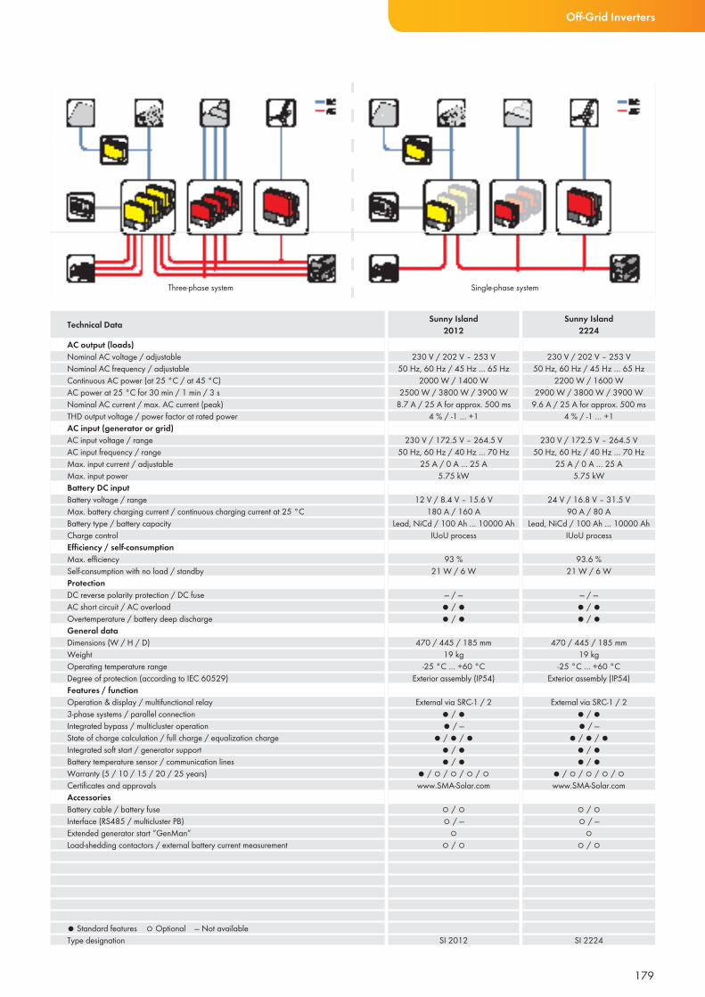
179
Off-Grid Inverters
AC output (loads)Nominal AC voltage / adjustableNominal AC frequency / adjustableContinuous AC power (at 25 °C / at 45 °C)AC power at 25 °C for 30 min / 1 min / 3 sNominal AC current / max. AC current (peak)THD output voltage / power factor at rated powerAC input (generator or grid)AC input voltage / rangeAC input frequency / rangeMax. input current / adjustableMax. input powerBattery DC inputBattery voltage / rangeMax. battery charging current / continuous charging current at 25 °CBattery type / battery capacityCharge controlEffi ciency / self-consumption Max. effi ciencySelf-consumption with no load / standbyProtectionDC reverse polarity protection / DC fuseAC short circuit / AC overloadOvertemperature / battery deep dischargeGeneral dataDimensions (W / H / D)WeightOperating temperature rangeDegree of protection (according to IEC 60529)Features / functionOperation & display / multifunctional relay3-phase systems / parallel connectionIntegrated bypass / multicluster operationState of charge calculation / full charge / equalization chargeIntegrated soft start / generator supportBattery temperature sensor / communication linesWarranty (5 / 10 / 15 / 20 / 25 years)Certifi cates and approvalsAccessoriesBattery cable / battery fuseInterface (RS485 / multicluster PB)Extended generator start “GenMan”Load-shedding contactors / external battery current measurement
● Standard features ○ Optional — Not availableType designation
230 V / 202 V – 253 V50 Hz, 60 Hz / 45 Hz … 65 Hz
2000 W / 1400 W2500 W / 3800 W / 3900 W
8.7 A / 25 A for approx. 500 ms 4 % / -1 … +1
230 V / 172.5 V – 264.5 V50 Hz, 60 Hz / 40 Hz … 70 Hz
25 A / 0 A … 25 A5.75 kW
12 V / 8.4 V – 15.6 V180 A / 160 A
Lead, NiCd / 100 Ah … 10000 AhIUoU process
93 %
21 W / 6 W
— / —● / ●● / ●
470 / 445 / 185 mm19 kg
-25 °C … +60 °CExterior assembly (IP54)
External via SRC-1 / 2● / ●● / —
● / ● / ●● / ●● / ●
● / ○ / ○ / ○ / ○www.SMA-Solar.com
○ / ○ ○ / —
○○ / ○
SI 2012
230 V / 202 V – 253 V50 Hz, 60 Hz / 45 Hz … 65 Hz
2200 W / 1600 W2900 W / 3800 W / 3900 W
9.6 A / 25 A for approx. 500 ms 4 % / -1 … +1
230 V / 172.5 V – 264.5 V50 Hz, 60 Hz / 40 Hz … 70 Hz
25 A / 0 A … 25 A5.75 kW
24 V / 16.8 V – 31.5 V90 A / 80 A
Lead, NiCd / 100 Ah … 10000 AhIUoU process
93.6 %
21 W / 6 W
— / —● / ●● / ●
470 / 445 / 185 mm19 kg
-25 °C … +60 °CExterior assembly (IP54)
External via SRC-1 / 2● / ●● / —
● / ● / ●● / ●● / ●
● / ○ / ○ / ○ / ○www.SMA-Solar.com
○ / ○ ○ / —
○○ / ○
SI 2224
Technical Data Sunny Island2012
Sunny Island2224
Three-phase system Single-phase system
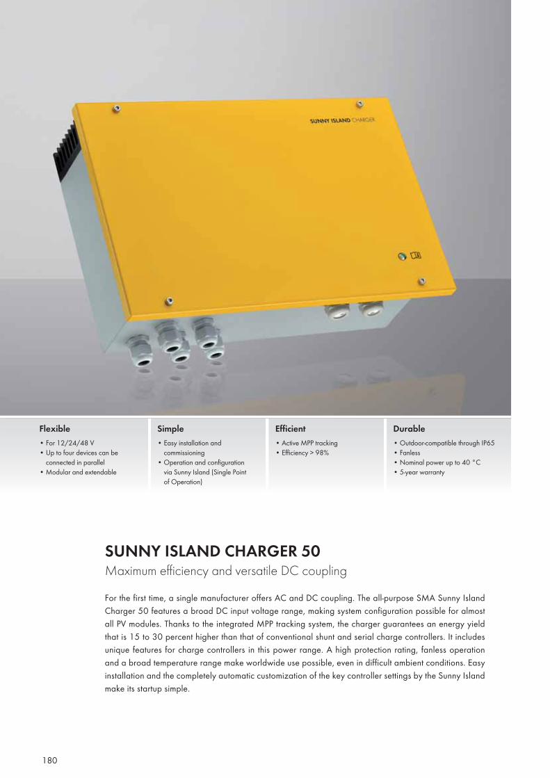
180
SUNNY ISLAND CHARGER 50Maximum efficiency and versatile DC couplingFor the first time, a single manufacturer offers AC and DC coupling. The all-purpose SMA Sunny Island Charger 50 features a broad DC input voltage range, making system configuration possible for almost all PV modules. Thanks to the integrated MPP tracking system, the charger guarantees an energy yield that is 15 to 30 percent higher than that of conventional shunt and serial charge controllers. It includes unique features for charge controllers in this power range. A high protection rating, fanless operation and a broad temperature range make worldwide use possible, even in difficult ambient conditions. Easy installation and the completely automatic customization of the key controller settings by the Sunny Island make its startup simple.
Flexible• For 12/24/48 V• Up to four devices can be
connected in parallel• Modular and extendable
Simple• Easy installation and commissioning• Operation and configuration
via Sunny Island (Single Point of Operation)
Efficient• Active MPP tracking• Efficiency > 98%
Durable• Outdoor-compatible through IP65• Fanless• Nominal power up to 40 °C• 5-year warranty
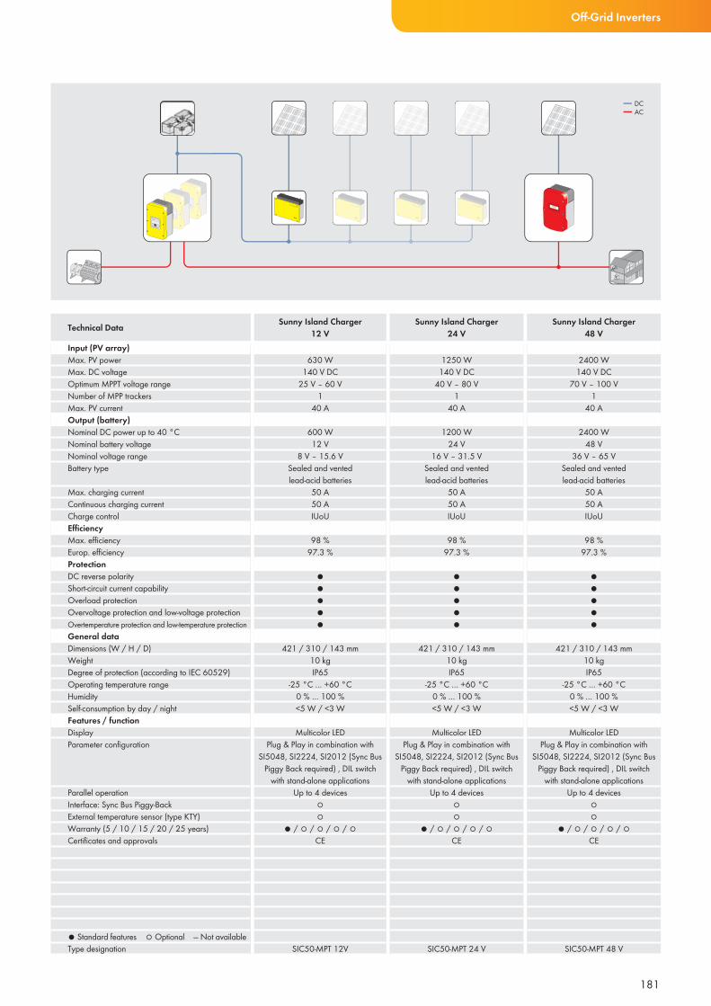
181
Off-Grid Inverters
Input (PV array)Max. PV powerMax. DC voltageOptimum MPPT voltage rangeNumber of MPP trackersMax. PV currentOutput (battery)Nominal DC power up to 40 °CNominal battery voltageNominal voltage rangeBattery type
Max. charging currentContinuous charging currentCharge controlEffi ciencyMax. effi ciencyEurop. effi ciencyProtection DC reverse polarityShort-circuit current capabilityOverload protectionOvervoltage protection and low-voltage protectionOvertemperature protection and low-temperature protectionGeneral dataDimensions (W / H / D)WeightDegree of protection (according to IEC 60529)Operating temperature rangeHumiditySelf-consumption by day / nightFeatures / functionDisplayParameter confi guration
Parallel operationInterface: Sync Bus Piggy-BackExternal temperature sensor (type KTY)Warranty (5 / 10 / 15 / 20 / 25 years)Certifi cates and approvals
● Standard features ○ Optional — Not availableType designation
Technical Data
630 W140 V DC
25 V – 60 V1
40 A
600 W12 V
8 V – 15.6 VSealed and vented lead-acid batteries
50 A50 AIUoU
98 %97.3 %
●●●●●
421 / 310 / 143 mm10 kgIP65
-25 °C … +60 °C 0 % … 100 %<5 W / <3 W
Multicolor LEDPlug & Play in combination with
SI5048, SI2224, SI2012 (Sync Bus Piggy Back required) , DIL switch
with stand-alone applicationsUp to 4 devices
○○
● / ○ / ○ / ○ / ○CE
SIC50-MPT 12V
1250 W140 V DC
40 V – 80 V1
40 A
1200 W24 V
16 V – 31.5 VSealed and vented lead-acid batteries
50 A50 AIUoU
98 %97.3 %
●●●●●
421 / 310 / 143 mm10 kgIP65
-25 °C … +60 °C 0 % … 100 %<5 W / <3 W
Multicolor LEDPlug & Play in combination with
SI5048, SI2224, SI2012 (Sync Bus Piggy Back required) , DIL switch
with stand-alone applicationsUp to 4 devices
○○
● / ○ / ○ / ○ / ○CE
SIC50-MPT 24 V
2400 W140 V DC
70 V – 100 V1
40 A
2400 W48 V
36 V – 65 VSealed and vented lead-acid batteries
50 A50 AIUoU
98 %97.3 %
●●●●●
421 / 310 / 143 mm10 kgIP65
-25 °C … +60 °C 0 % … 100 %<5 W / <3 W
Multicolor LEDPlug & Play in combination with
SI5048, SI2224, SI2012 (Sync Bus Piggy Back required) , DIL switch
with stand-alone applicationsUp to 4 devices
○○
● / ○ / ○ / ○ / ○CE
SIC50-MPT 48 V
Sunny Island Charger12 V
Sunny Island Charger24 V
Sunny Island Charger48 V
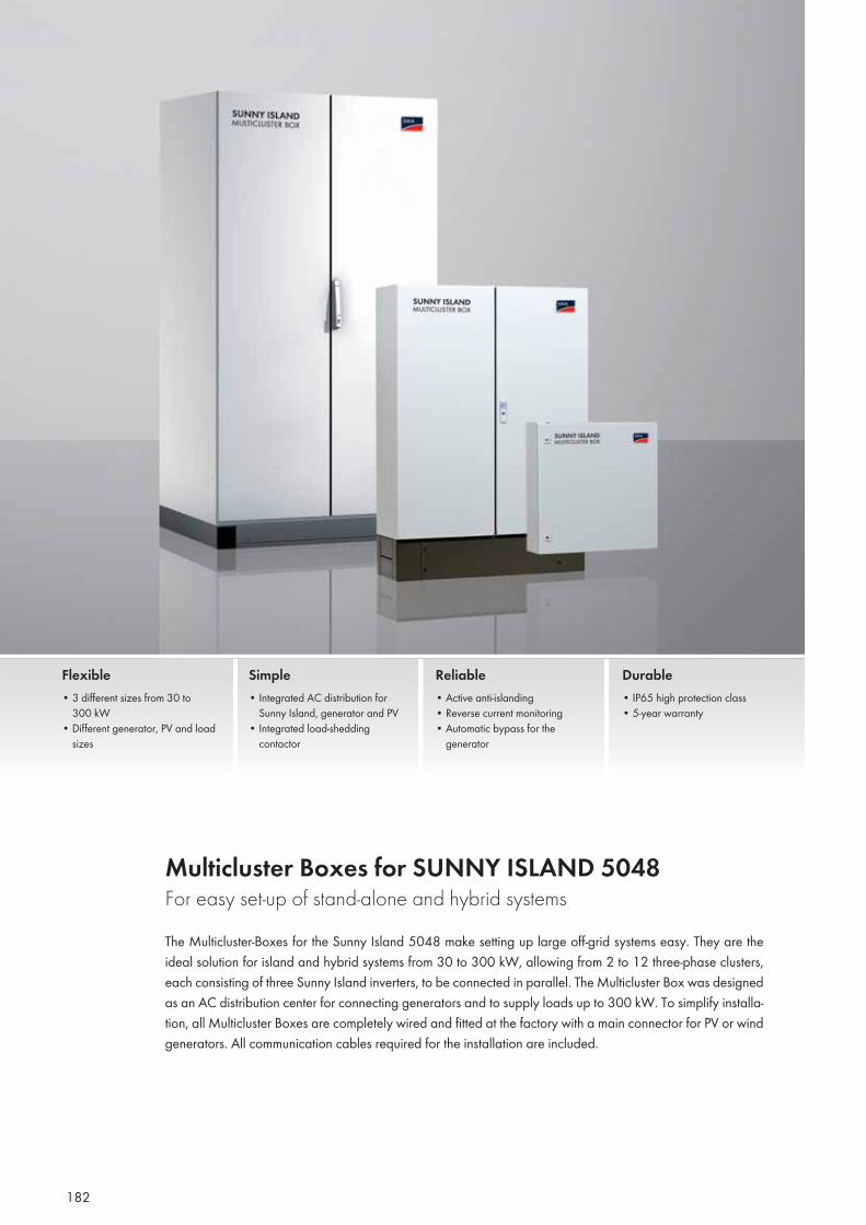
182
Multicluster Boxes for SUNNY ISLAND 5048 For easy set-up of stand-alone and hybrid systemsThe Multicluster-Boxes for the Sunny Island 5048 make setting up large off-grid systems easy. They are the ideal solution for island and hybrid systems from 30 to 300 kW, allowing from 2 to 12 three-phase clusters, each consisting of three Sunny Island inverters, to be connected in parallel. The Multicluster Box was designed as an AC distribution center for connecting generators and to supply loads up to 300 kW. To simplify installa-tion, all Multicluster Boxes are completely wired and fitted at the factory with a main connector for PV or wind generators. All communication cables required for the installation are included.
Flexible• 3 different sizes from 30 to
300 kW• Different generator, PV and load
sizes
Simple• Integrated AC distribution for
Sunny Island, generator and PV• Integrated load-shedding
contactor
Reliable• Active anti-islanding• Reverse current monitoring • Automatic bypass for the
generator
Durable• IP65 high protection class• 5-year warranty
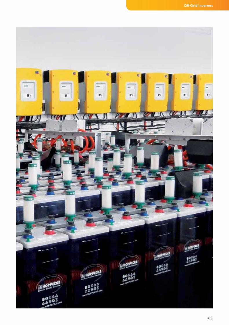
183
Off-Grid Inverters
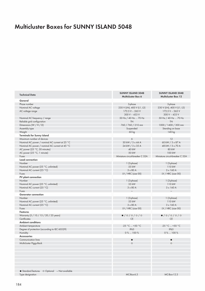
184
Multicluster Boxes for SUNNY ISLAND 5048
GeneralPhase numberNominal AC voltageAC voltage range
Nominal AC frequency / rangeReliable grid confi gurationDimensions (W / H / D)Assembly typeWeightTerminals for Sunny IslandMaximum number of devicesNominal AC power / nominal AC current at 25 °CNominal AC power / nominal AC current at 45 °CAC power (25 °C, 30 minutes)AC power (25 °C, 1 minute)FusesLoad connectionNumberNominal AC power (25 °C, unlimited)Nominal AC current (25 °C)FusesPV plant connectionNumberNominal AC power (25 °C, unlimited)Nominal AC current (25 °C)FusesGenerator connectionNumberNominal AC power (25 °C, unlimited)Nominal AC current (25 °C)FusesFeaturesWarranty (5 / 10 / 15 / 20 / 25 years)Certifi catesAmbient conditionsAmbient temperatureDegree of protection (according to IEC 60529)HumidityAccessoriesCommunication linesMulticluster Piggy-Back
● Standard features ○ Optional — Not availableType designation
3-phase230 V (LN), 400 V (L1, L2)
172.5 V – 265 V300 V – 433 V
50 Hz / 40 Hz … 70 HzTN
760 / 760 / 210 mmSuspended
60 kg
630 kW / 3 x 44 A24 kW / 3 x 35 A
40 kW50 kW
Miniature circuit-breaker C 32A
1 (3-phase)55 kW
3 x 80 ALV / HRC (size 00)
1 (3-phase)55 kW
3 x 80 A—
1 (3-phase)55 kW
3 x 80 ALV / HRC (size 00)
● / ○ / ○ / ○ / ○CE
-25 °C … +50 °CIP65
0 % … 100 %
●○
MC-Box-6.3
3-phase230 V (LN), 400 V (L1, L2)
172.5 V – 265 V300 V – 433 V
50 Hz / 40 Hz … 70 HzTN
1000 / 1400 / 300 mmStanding on base
140 kg
1260 kW / 3 x 87 A48 kW / 3 x 70 A
80 kW100 kW
Miniature circuit-breaker C 32A
1 (3-phase)110 kW
3 x 160 ALV / HRC (size 00)
1 (3-phase)110 kW
3 x 160 A—
1 (3-phase)110 kW
3 x 160 ALV / HRC (size 00)
● / ○ / ○ / ○ / ○CE
-25 °C … +50 °CIP65
0 % … 100 %
●○
MC-Box-12.3
Technical Data SUNNY ISLAND 5048Multicluster Box 6
SUNNY ISLAND 5048Multicluster Box 12
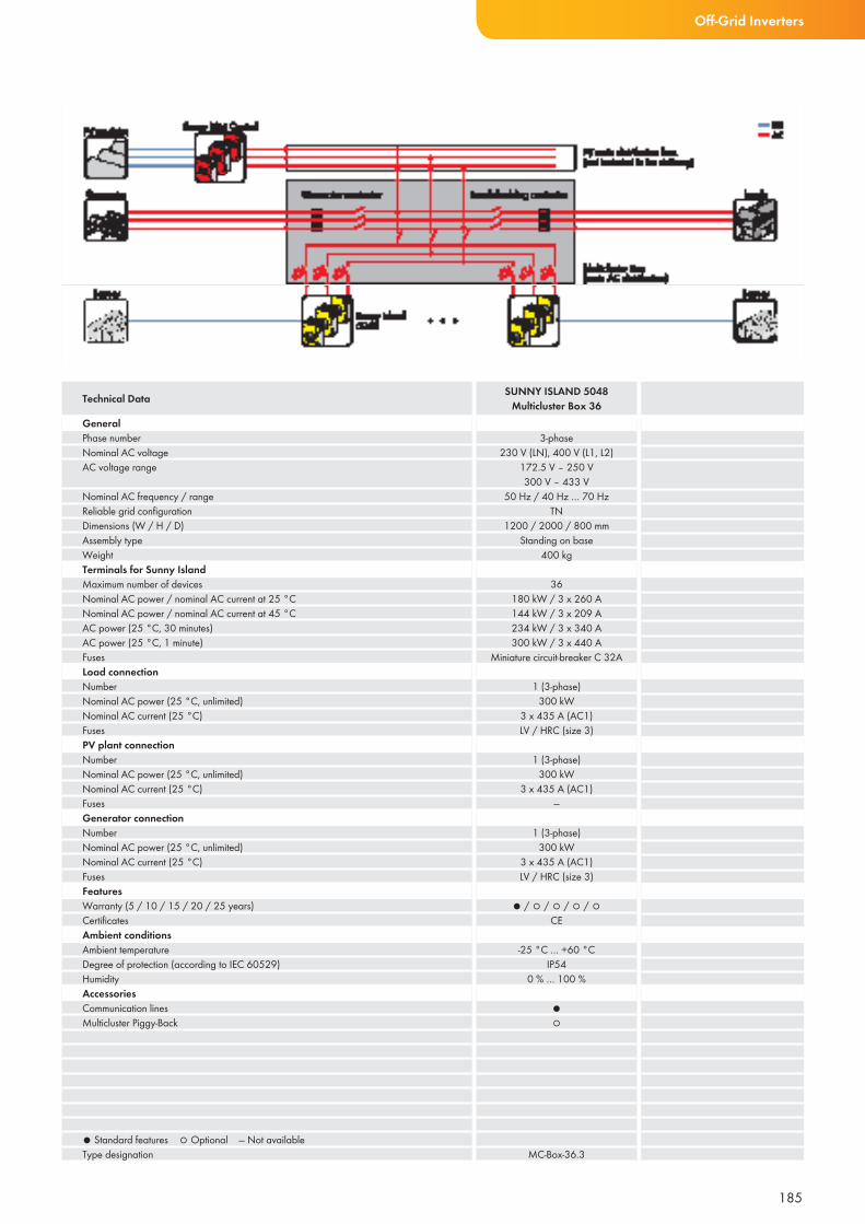
185
Off-Grid Inverters
GeneralPhase numberNominal AC voltageAC voltage range
Nominal AC frequency / rangeReliable grid confi gurationDimensions (W / H / D)Assembly typeWeightTerminals for Sunny IslandMaximum number of devicesNominal AC power / nominal AC current at 25 °CNominal AC power / nominal AC current at 45 °CAC power (25 °C, 30 minutes)AC power (25 °C, 1 minute)FusesLoad connectionNumberNominal AC power (25 °C, unlimited)Nominal AC current (25 °C)FusesPV plant connectionNumberNominal AC power (25 °C, unlimited)Nominal AC current (25 °C)FusesGenerator connectionNumberNominal AC power (25 °C, unlimited)Nominal AC current (25 °C)FusesFeaturesWarranty (5 / 10 / 15 / 20 / 25 years)Certifi catesAmbient conditionsAmbient temperatureDegree of protection (according to IEC 60529)HumidityAccessoriesCommunication linesMulticluster Piggy-Back
● Standard features ○ Optional — Not availableType designation
3-phase230 V (LN), 400 V (L1, L2)
172.5 V – 250 V300 V – 433 V
50 Hz / 40 Hz … 70 HzTN
1200 / 2000 / 800 mmStanding on base
400 kg
36180 kW / 3 x 260 A144 kW / 3 x 209 A234 kW / 3 x 340 A300 kW / 3 x 440 A
Miniature circuit-breaker C 32A
1 (3-phase)300 kW
3 x 435 A (AC1)LV / HRC (size 3)
1 (3-phase)300 kW
3 x 435 A (AC1)—
1 (3-phase)300 kW
3 x 435 A (AC1)LV / HRC (size 3)
● / ○ / ○ / ○ / ○CE
-25 °C … +60 °CIP54
0 % … 100 %
●○
MC-Box-36.3
Technical Data SUNNY ISLAND 5048Multicluster Box 36
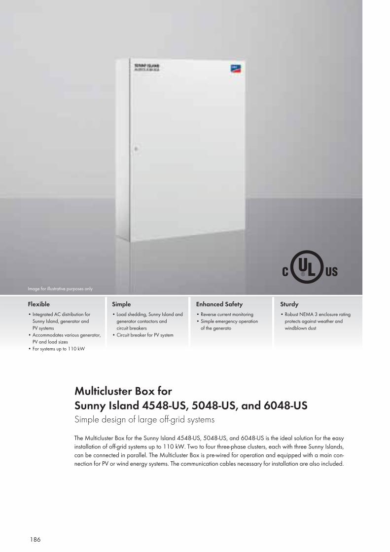
Image for illustrative purposes only
186
Multicluster Box forSunny Island 4548-US, 5048-US, and 6048-USSimple design of large off-grid systemsThe Multicluster Box for the Sunny Island 4548-US, 5048-US, and 6048-US is the ideal solution for the easy installation of off-grid systems up to 110 kW. Two to four three-phase clusters, each with three Sunny Islands, can be connected in parallel. The Multicluster Box is pre-wired for operation and equipped with a main con-nection for PV or wind energy systems. The communication cables necessary for installation are also included.
Flexible• Integrated AC distribution for Sunny Island, generator and PV systems• Accommodates various generator, PV and load sizes• For systems up to 110 kW
Simple• Load shedding, Sunny Island and generator contactors and circuit breakers• Circuit breaker for PV system
Enhanced Safety• Reverse current monitoring• Simple emergency operation of the generato
Sturdy• Robust NEMA 3 enclosure rating protects against weather and windblown dust
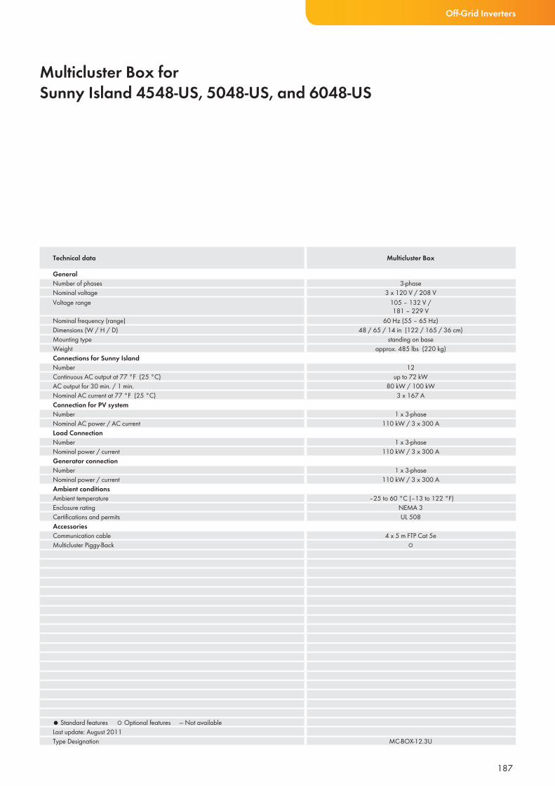
187
Multicluster Box forSunny Island 4548-US, 5048-US, and 6048-US
Technical data Multicluster Box
GeneralNumber of phases 3-phaseNominal voltage 3 x 120 V / 208 VVoltage range 105 – 132 V /
181 – 229 VNominal frequency (range) 60 Hz (55 – 65 Hz)Dimensions (W / H / D) 48 / 65 / 14 in (122 / 165 / 36 cm)Mounting type standing on baseWeight approx. 485 lbs (220 kg)Connections for Sunny IslandNumber 12Continuous AC output at 77 °F (25 °C) up to 72 kWAC output for 30 min. / 1 min. 80 kW / 100 kWNominal AC current at 77 °F (25 °C) 3 x 167 AConnection for PV systemNumber 1 x 3-phaseNominal AC power / AC current 110 kW / 3 x 300 ALoad ConnectionNumber 1 x 3-phaseNominal power / current 110 kW / 3 x 300 AGenerator connectionNumber 1 x 3-phaseNominal power / current 110 kW / 3 x 300 AAmbient conditionsAmbient temperature –25 to 60 °C (–13 to 122 °F)Enclosure rating NEMA 3Certifications and permits UL 508AccessoriesCommunication cable 4 x 5 m FTP Cat 5eMulticluster Piggy-Back ○
● Standard features ○ Optional features — Not availableLast update: August 2011Type Designation MC-BOX-12.3U
Off-Grid Inverters
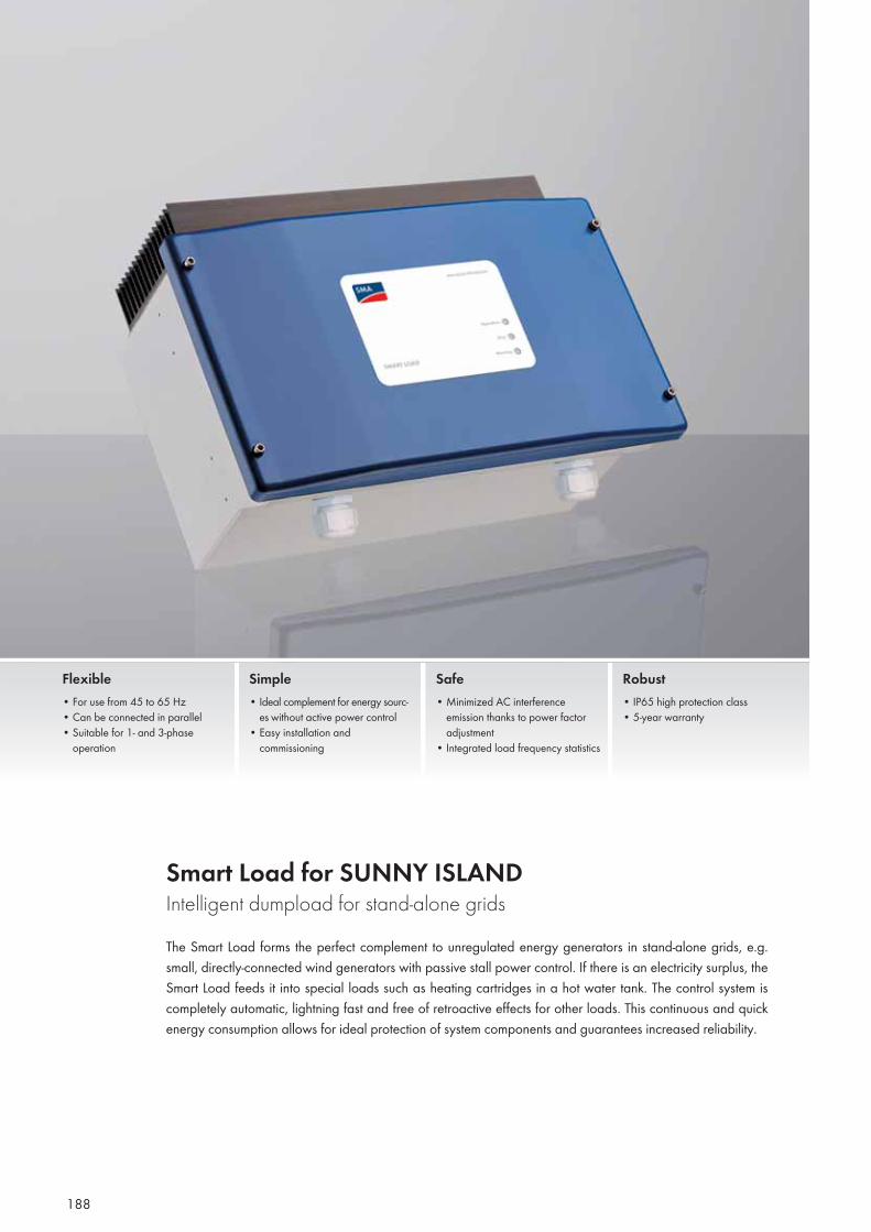
188
Smart Load for SUNNY ISLAND Intelligent dumpload for stand-alone gridsThe Smart Load forms the perfect complement to unregulated energy generators in stand-alone grids, e.g. small, directly-connected wind generators with passive stall power control. If there is an electricity surplus, the Smart Load feeds it into special loads such as heating cartridges in a hot water tank. The control system is completely automatic, lightning fast and free of retroactive effects for other loads. This continuous and quick energy consumption allows for ideal protection of system components and guarantees increased reliability.
Flexible • For use from 45 to 65 Hz• Can be connected in parallel• Suitable for 1- and 3-phase
operation
Simple • Ideal complement for energy sourc-
es without active power control• Easy installation and
commissioning
Safe • Minimized AC interference
emission thanks to power factor adjustment
• Integrated load frequency statistics
Robust • IP65 high protection class• 5-year warranty
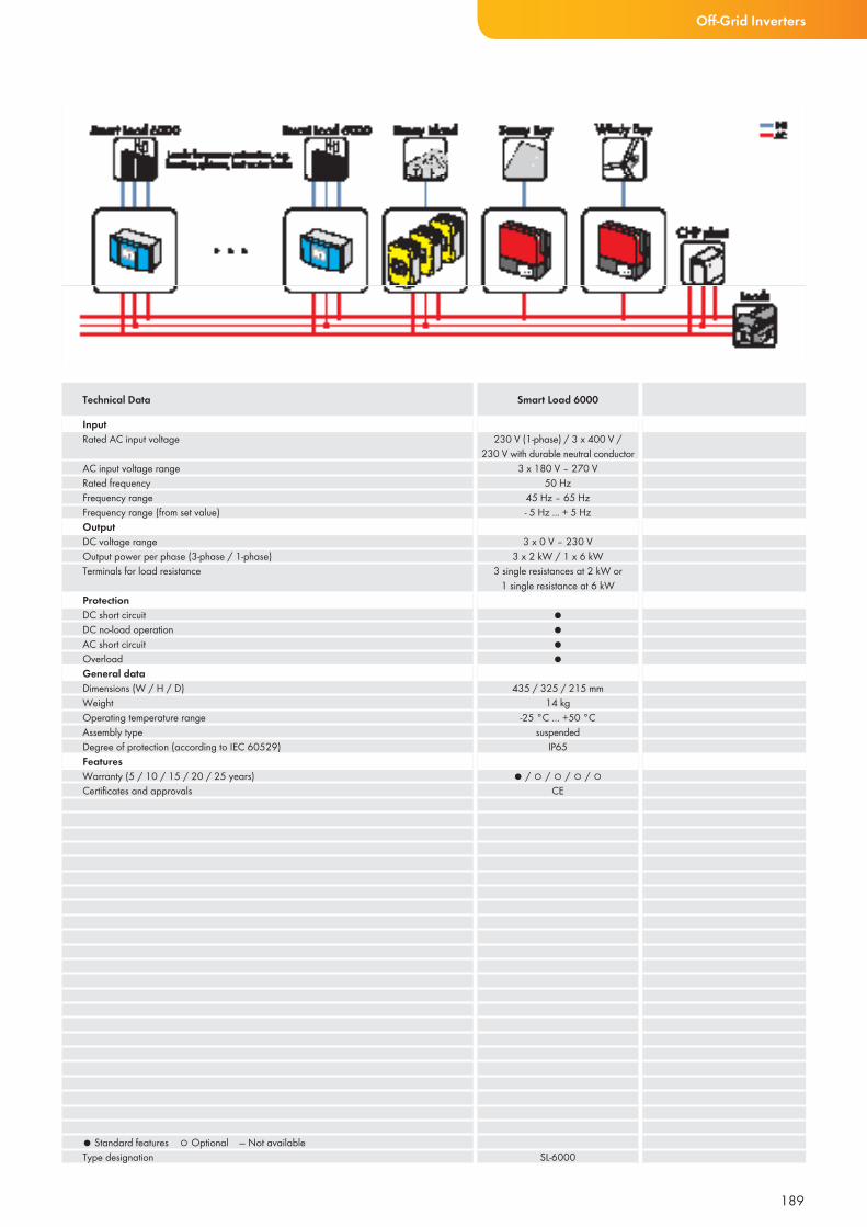
189
Off-Grid Inverters
InputRated AC input voltage
AC input voltage rangeRated frequencyFrequency rangeFrequency range (from set value)OutputDC voltage rangeOutput power per phase (3-phase / 1-phase)Terminals for load resistance
ProtectionDC short circuitDC no-load operationAC short circuitOverloadGeneral data Dimensions (W / H / D)WeightOperating temperature rangeAssembly typeDegree of protection (according to IEC 60529)FeaturesWarranty (5 / 10 / 15 / 20 / 25 years)Certifi cates and approvals
● Standard features ○ Optional — Not availableType designation
230 V (1-phase) / 3 x 400 V / 230 V with durable neutral conductor
3 x 180 V – 270 V50 Hz
45 Hz – 65 Hz- 5 Hz ... + 5 Hz
3 x 0 V – 230 V3 x 2 kW / 1 x 6 kW
3 single resistances at 2 kW or 1 single resistance at 6 kW
●●●●
435 / 325 / 215 mm14 kg
-25 °C … +50 °Csuspended
IP65
● / ○ / ○ / ○ / ○CE
SL-6000
Technical Data Smart Load 6000
WIND POWER INVERTERS
190
191

192
WINDY BOY 5000A / 6000AThe performance class up to 18 kWThe Windy Boy 5000A, 6000A not only feature a maximum efficiency of 96.1 percent, but are also suited for the development of three-phase grid-feeding wind energy plants. The integrated SMA Power Balancer pre-vents undue load unbalance. The plant is also able to feed-in even if individual phases fail. The weather-proof enclosure and the wide temperature range allow for installation at almost any location. Thanks to the OptiCool temperature management system, these models work with maximum output at outdoor temperatures of up to 45 °C (113 °F). In case of an unlikely problem, the worldwide SMA Service and comprehensive warranty program provide maximum security.
Efficient• Up to 96.1% efficiency• Can be combined to form three-
phase units with up to 18 kW output• Integrated SMA Power Balancer• OptiCool™ ensures continuous op-
eration even at high temperatures
Easy to Use• Programmable polynomial curve
enables free selection of turbines• Certified for the most countries
(SMA Grid Guard)
Safe• Galvanic isolation• Compatible with Windy Boy
Protection Box 600
Reliable• Worldwide SMA Service
including Service Line• Comprehensive SMA
warranty program
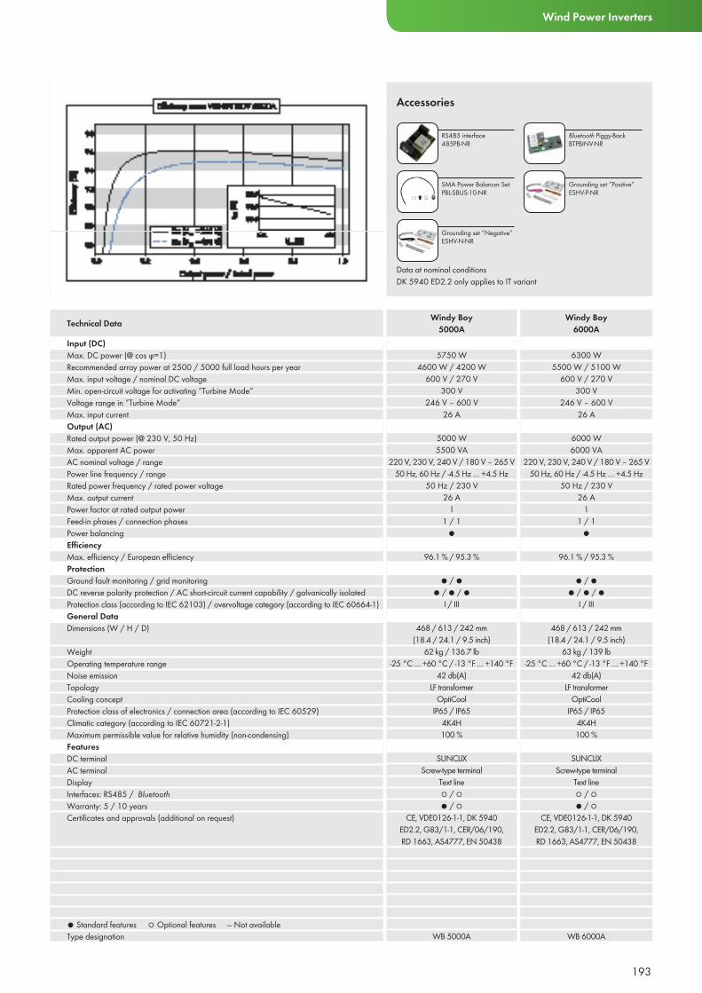
193
Wind Power Inverters
Input (DC)Max. DC power (@ cos ϕ=1)Recommended array power at 2500 / 5000 full load hours per yearMax. input voltage / nominal DC voltageMin. open-circuit voltage for activating ”Turbine Mode”Voltage range in ”Turbine Mode”Max. input currentOutput (AC)Rated output power (@ 230 V, 50 Hz)Max. apparent AC powerAC nominal voltage / rangePower line frequency / rangeRated power frequency / rated power voltageMax. output currentPower factor at rated output powerFeed-in phases / connection phasesPower balancingEffi ciencyMax. effi ciency / European effi ciency ProtectionGround fault monitoring / grid monitoringDC reverse polarity protection / AC short-circuit current capability / galvanically isolatedProtection class (according to IEC 62103) / overvoltage category (according to IEC 60664-1) General DataDimensions (W / H / D)
WeightOperating temperature rangeNoise emissionTopologyCooling conceptProtection class of electronics / connection area (according to IEC 60529)Climatic category (according to IEC 60721-2-1)Maximum permissible value for relative humidity (non-condensing)FeaturesDC terminalAC terminalDisplayInterfaces: RS485 / BluetoothWarranty: 5 / 10 yearsCertifi cates and approvals (additional on request)
● Standard features ○ Optional features — Not availableType designation
5750 W4600 W / 4200 W
600 V / 270 V300 V
246 V – 600 V26 A
5000 W5500 VA
220 V, 230 V, 240 V / 180 V – 265 V50 Hz, 60 Hz / -4.5 Hz … +4.5 Hz
50 Hz / 230 V26 A
11 / 1
●
96.1 % / 95.3 %
● / ●● / ● / ●
I / III
468 / 613 / 242 mm(18.4 / 24.1 / 9.5 inch)
62 kg / 136.7 lb-25 °C … +60 °C / -13 °F … +140 °F
42 db(A)LF transformer
OptiCoolIP65 / IP65
4K4H100 %
SUNCLIXScrew-type terminal
Text line○ / ○● / ○
CE, VDE0126-1-1, DK 5940 ED2.2, G83/1-1, CER/06/190, RD 1663, AS4777, EN 50438
WB 5000A
6300 W5500 W / 5100 W
600 V / 270 V300 V
246 V – 600 V26 A
6000 W6000 VA
220 V, 230 V, 240 V / 180 V – 265 V50 Hz, 60 Hz / -4.5 Hz … +4.5 Hz
50 Hz / 230 V26 A
11 / 1
●
96.1 % / 95.3 %
● / ●● / ● / ●
I / III
468 / 613 / 242 mm(18.4 / 24.1 / 9.5 inch)
63 kg / 139 lb-25 °C … +60 °C / -13 °F … +140 °F
42 db(A)LF transformer
OptiCoolIP65 / IP65
4K4H100 %
SUNCLIXScrew-type terminal
Text line○ / ○● / ○
CE, VDE0126-1-1, DK 5940 ED2.2, G83/1-1, CER/06/190, RD 1663, AS4777, EN 50438
WB 6000A
Technical Data Windy Boy5000A
Windy Boy6000A
Accessories
RS485 interface 485PB-NR
Bluetooth Piggy-BackBTPBINV-NR
SMA Power Balancer SetPBL-SBUS-10-NR
Grounding set ”Negative”ESHV-N-NR
Grounding set ”Positive”ESHV-P-NR
Data at nominal conditionsDK 5940 ED2.2 only applies to IT variant
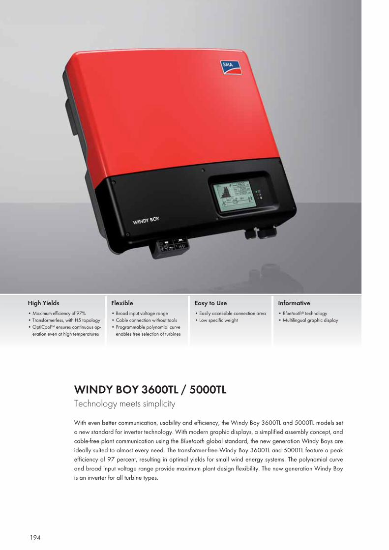
194
WINDY BOY 3600TL / 5000TL Technology meets simplicityWith even better communication, usability and efficiency, the Windy Boy 3600TL and 5000TL models set a new standard for inverter technology. With modern graphic displays, a simplified assembly concept, and cable-free plant communication using the Bluetooth global standard, the new generation Windy Boys are ideally suited to almost every need. The transformer-free Windy Boy 3600TL and 5000TL feature a peak efficiency of 97 percent, resulting in optimal yields for small wind energy systems. The polynomial curve and broad input voltage range provide maximum plant design flexibility. The new generation Windy Boy is an inverter for all turbine types.
High Yields• Maximum efficiency of 97%• Transformerless, with H5 topology• OptiCool™ ensures continuous op-
eration even at high temperatures
Flexible• Broad input voltage range• Cable connection without tools• Programmable polynomial curve
enables free selection of turbines
Easy to Use• Easily accessible connection area• Low specific weight
Informative• Bluetooth® technology• Multilingual graphic display
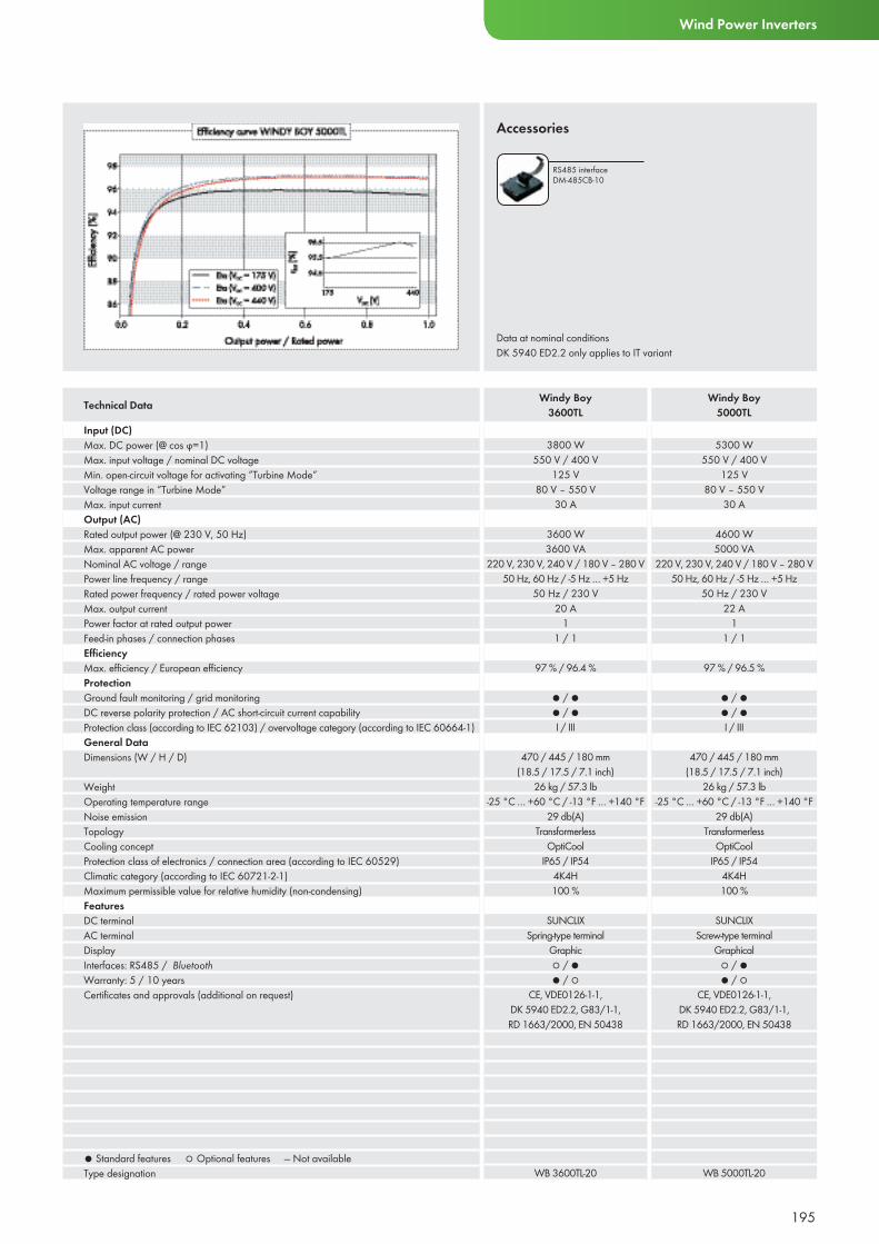
195
Wind Power Inverters
Input (DC)Max. DC power (@ cos ϕ=1)Max. input voltage / nominal DC voltageMin. open-circuit voltage for activating ”Turbine Mode”Voltage range in ”Turbine Mode”Max. input currentOutput (AC)Rated output power (@ 230 V, 50 Hz)Max. apparent AC powerNominal AC voltage / rangePower line frequency / rangeRated power frequency / rated power voltageMax. output currentPower factor at rated output powerFeed-in phases / connection phasesEffi ciencyMax. effi ciency / European effi ciency ProtectionGround fault monitoring / grid monitoringDC reverse polarity protection / AC short-circuit current capabilityProtection class (according to IEC 62103) / overvoltage category (according to IEC 60664-1) General DataDimensions (W / H / D)
WeightOperating temperature rangeNoise emissionTopologyCooling conceptProtection class of electronics / connection area (according to IEC 60529)Climatic category (according to IEC 60721-2-1)Maximum permissible value for relative humidity (non-condensing)FeaturesDC terminalAC terminalDisplayInterfaces: RS485 / BluetoothWarranty: 5 / 10 yearsCertifi cates and approvals (additional on request)
● Standard features ○ Optional features — Not availableType designation
3800 W550 V / 400 V
125 V80 V – 550 V
30 A
3600 W3600 VA
220 V, 230 V, 240 V / 180 V – 280 V50 Hz, 60 Hz / -5 Hz … +5 Hz
50 Hz / 230 V20 A
11 / 1
97 % / 96.4 %
● / ●● / ●I / III
470 / 445 / 180 mm(18.5 / 17.5 / 7.1 inch)
26 kg / 57.3 lb-25 °C … +60 °C / -13 °F … +140 °F
29 db(A)Transformerless
OptiCoolIP65 / IP54
4K4H100 %
SUNCLIXSpring-type terminal
Graphic○ / ●● / ○
CE, VDE0126-1-1, DK 5940 ED2.2, G83/1-1, RD 1663/2000, EN 50438
WB 3600TL-20
5300 W550 V / 400 V
125 V80 V – 550 V
30 A
4600 W5000 VA
220 V, 230 V, 240 V / 180 V – 280 V50 Hz, 60 Hz / -5 Hz … +5 Hz
50 Hz / 230 V22 A
11 / 1
97 % / 96.5 %
● / ●● / ●I / III
470 / 445 / 180 mm(18.5 / 17.5 / 7.1 inch)
26 kg / 57.3 lb-25 °C … +60 °C / -13 °F … +140 °F
29 db(A)Transformerless
OptiCoolIP65 / IP54
4K4H100 %
SUNCLIXScrew-type terminal
Graphical○ / ●● / ○
CE, VDE0126-1-1, DK 5940 ED2.2, G83/1-1, RD 1663/2000, EN 50438
WB 5000TL-20
Technical Data Windy Boy3600TL
Windy Boy5000TL
Data at nominal conditionsDK 5940 ED2.2 only applies to IT variant
Accessories
RS485 interface DM-485CB-10
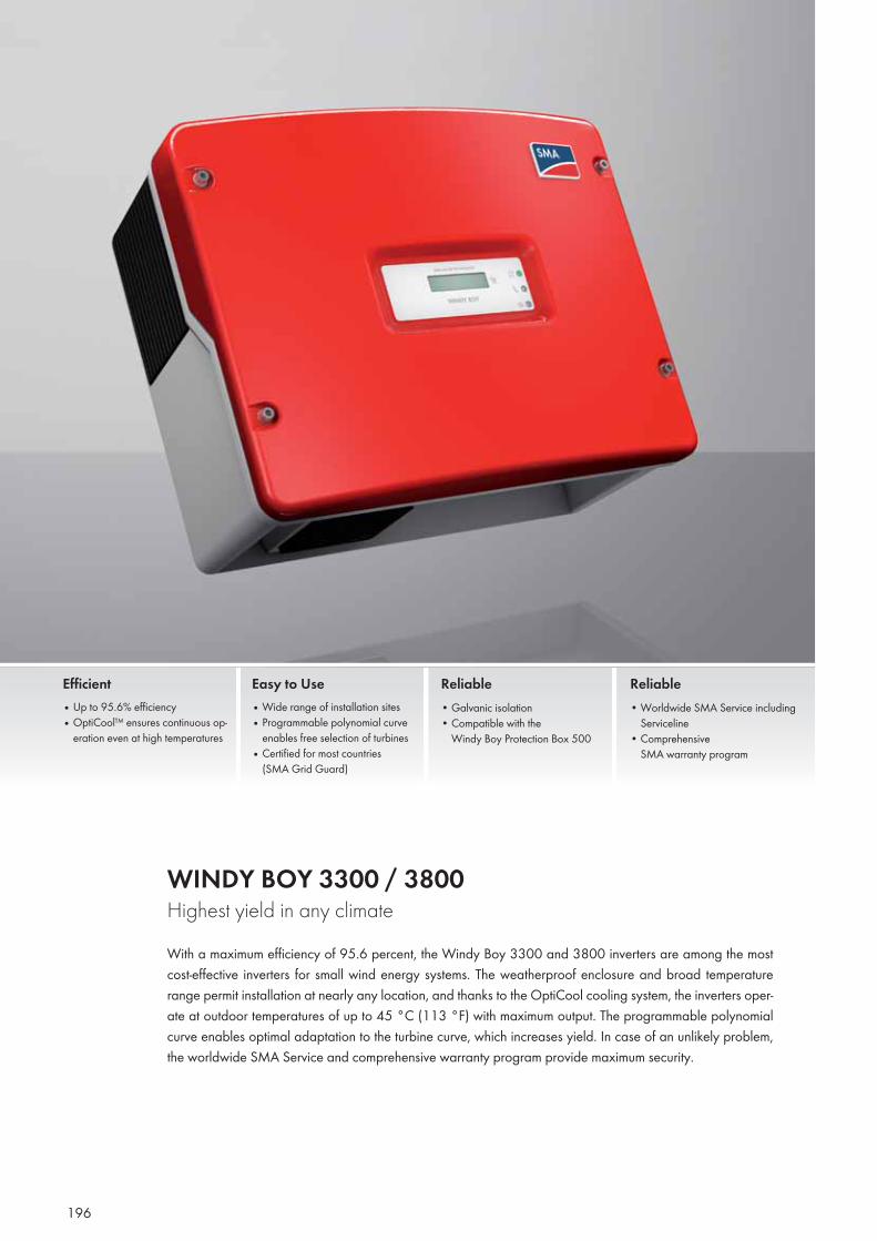
196
WINDY BOY 3300 / 3800 Highest yield in any climateWith a maximum efficiency of 95.6 percent, the Windy Boy 3300 and 3800 inverters are among the most cost-effective inverters for small wind energy systems. The weatherproof enclosure and broad temperature range permit installation at nearly any location, and thanks to the OptiCool cooling system, the inverters oper-ate at outdoor temperatures of up to 45 °C (113 °F) with maximum output. The programmable polynomial curve enables optimal adaptation to the turbine curve, which increases yield. In case of an unlikely problem, the worldwide SMA Service and comprehensive warranty program provide maximum security.
Efficient• Up to 95.6% efficiency• OptiCool™ ensures continuous op-
eration even at high temperatures
Easy to Use• Wide range of installation sites• Programmable polynomial curve
enables free selection of turbines• Certified for most countries
(SMA Grid Guard)
Reliable• Galvanic isolation• Compatible with the
Windy Boy Protection Box 500
Reliable• Worldwide SMA Service including
Serviceline• Comprehensive
SMA warranty program
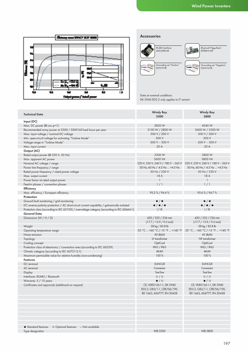
197
Wind Power Inverters
Input (DC)Max. DC power (@ cos ϕ=1)Recommended array power at 2500 / 5000 full load hours per yearMax. input voltage / nominal DC voltageMin. open-circuit voltage for activating ”Turbine Mode”Voltage range in ”Turbine Mode”Max. input currentOutput (AC)Rated output power (@ 230 V, 50 Hz)Max. apparent AC powerNominal AC voltage / rangePower line frequency / rangeRated power frequency / rated power voltageMax. output currentPower factor at rated output powerFeed-in phases / connection phasesEffi ciencyMax. effi ciency / European effi ciency ProtectionGround fault monitoring / grid monitoringDC reverse polarity protection / AC short-circuit current capability / galvanically isolatedProtection class (according to IEC 62103) / overvoltage category (according to IEC 60664-1) General DataDimensions (W / H / D)
WeightOperating temperature rangeNoise emissionTopologyCooling conceptProtection class of electronics / connection area (according to IEC 60529)Climatic category (according to IEC 60721-2-1)Maximum permissible value for relative humidity (non-condensing)FeaturesDC terminalAC terminalDisplayInterfaces: RS485 / BluetoothWarranty: 5 / 10 yearsCertifi cates and approvals (additional on request)
● Standard features ○ Optional features — Not availableType designation
3820 W3100 W / 2800 W
500 V / 200 V200 V
200 V – 500 V20 A
3300 W3600 VA
220 V, 230 V, 240 V / 180 V – 265 V50 Hz, 60 Hz / -4.5 Hz … +4.5 Hz
50 Hz / 230 V18 A
11 / 1
95.2 % / 94.4 %
● / ●● / ● / ●
I / III
450 / 352 / 236 mm(17.7 / 13.9 / 9.3 inch)
38 kg / 83.8 lb-25 °C … +60 °C / -13 °F … +140 °F
40 db(A)LF transformer
OptiCoolIP65 / IP65
4K4H100 %
SUNCLIXConnectorText line○ / ○● / ○
CE, VDE0126-1-1, DK 5940 ED2.2, G83/1-1, CER/06/190, RD 1663, AS4777, EN 50438
WB 3300
4040 W3600 W / 3300 W
500 V / 200 V200 V
200 V – 500 V20 A
3800 W3800 VA
220 V, 230 V, 240 V / 180 V – 265 V50 Hz, 60 Hz / -4.5 Hz … +4.5 Hz
50 Hz / 230 V18 A
11 / 1
95.6 % / 94.7 %
● / ●● / ● / ●
I / III
450 / 352 / 236 mm(17.7 / 13.9 / 9.3 inch)
38 kg / 83.8 lb-25 °C … +60 °C / -13 °F … +140 °F
42 db(A)NF transformer
OptiCoolIP65 / IP65
4K4H100 %
SUNCLIXConnectorText line○ / ○● / ○
CE, VDE0126-1-1, DK 5940 ED2.2, G83/1-1, CER/06/190, RD 1663, AS4777, EN 50438
WB 3800
Technical Data Windy Boy3300
Windy Boy3800
Data at nominal conditionsDK 5940 ED2.2 only applies to IT variant
Accessories
RS485 interface 485USPB-NR
Bluetooth Piggy-BackBTPBINV-NR
Grounding set ”Positive”ESHV-P-NR
Grounding set ”Negative”ESHV-N-NR

198
WINDY BOY 2000HF / 2500HF / 3000HFNarrow and compact for high yieldsPacked full of the latest SMA technology, the Windy Boy HF series provides the highest yields for transformer-based inverters in this performance class. Installation is now easier than ever thanks to the new SUNCLIX® DC connector system and an easily accessible configuration area. Mounting has also seen simplified due to a reduction in weight. The programmable polynomial curve and the broad input voltage range also offer great freedom in wind turbine selection and enable grid-feeding even at low wind speeds. The modern graphic display and wireless Bluetooth communication system make the devices highly user-friendly.
High Yields• Maximum efficiency over 96%• OptiCool™ ensures continuous op-
eration even at high temperatures
Flexible• Programmable polynomial curve
enables free selection of turbines• Broader input voltage range
Easy to Use• Fast and simple connection
Informative• Bluetooth® technology• Multi-language graphic display
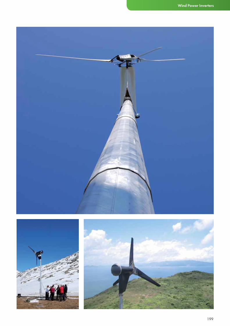
199
Wind Power Inverters
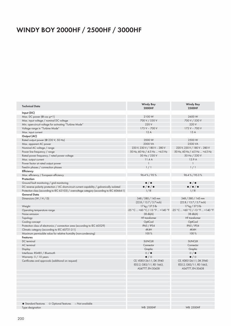
200
WINDY BOY 2000HF / 2500HF / 3000HF
Input (DC)Max. DC power (@ cos ϕ=1)Max. input voltage / nominal DC voltageMin. open-circuit voltage for activating ”Turbine Mode”Voltage range in ”Turbine Mode”Max. input currentOutput (AC)Rated output power (@ 230 V, 50 Hz)Max. apparent AC powerNominal AC voltage / rangePower line frequency / rangeRated power frequency / rated power voltageMax. output currentPower factor at rated output powerFeed-in phases / connection phasesEffi ciencyMax. effi ciency / European effi ciency ProtectionGround fault monitoring / grid monitoringDC reverse polarity protection / AC short-circuit current capability / galvanically isolatedProtection class (according to IEC 62103) / overvoltage category (according to IEC 60664-1) General DataDimensions (W / H / D)
WeightOperating temperature rangeNoise emissionTopologyCooling conceptProtection class of electronics / connection area (according to IEC 60529)Climatic category (according to IEC 60721-2-1)Maximum permissible value for relative humidity (non-condensing)FeaturesDC terminalAC terminalDisplayInterfaces: RS485 / BluetoothWarranty: 5 / 10 yearsCertifi cates and approvals (additional on request)
● Standard features ○ Optional features — Not availableType designation
2100 W700 V / 530 V
220 V175 V – 700 V
12 A
2000 W2000 VA
220 V, 230 V / 180 V – 280 V50 Hz, 60 Hz / -4.5 Hz … +4.5 Hz
50 Hz / 230 V11.4 A
11 / 1
96.4 % / 95 %
● / ●● / ● / ●
I / III
348 / 580 / 145 mm(22.8 / 13.7 / 5.7 inch)
17 kg / 37.5 lb-25 °C … +60 °C / -13 °F … +140 °F
38 db(A)HF transformer
OptiCoolIP65 / IP54
4K4H100 %
SUNCLIXConnectorGraphic○ / ●● / ○
CE, VDE0126-1-1, DK 5940 ED2.2, G83/1-1, RD 1663,
AS4777, EN 50438
WB 2000HF
2600 W700 V / 530 V
220 V175 V – 700 V
15 A
2500 W2500 VA
220 V, 230 V / 180 V – 280 V50 Hz, 60 Hz / -4.5 Hz … +4.5 Hz
50 Hz / 230 V13.9 A
11 / 1
96.4 % / 95.3 %
● / ●● / ● / ●
I / III
348 / 580 / 145 mm(22.8 / 13.7 / 5.7 inch)
17 kg / 37.5 lb-25 °C … +60 °C / -13 °F … +140 °F
38 db(A)HF transformer
OptiCoolIP65 / IP54
4K4H100 %
SUNCLIXConnectorGraphic○ / ●● / ○
CE, VDE0126-1-1, DK 5940 ED2.2, G83/1-1, RD 1663,
AS4777, EN 50438
WB 2500HF
Technical Data Windy Boy2000HF
Windy Boy2500HF
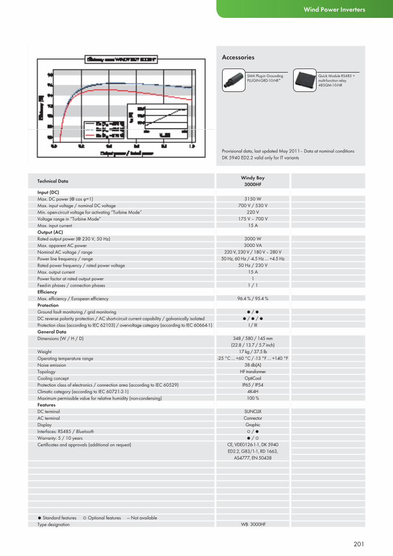
201
Wind Power Inverters
Provisional data, last updated May 2011– Data at nominal conditionsDK 5940 ED2.2 valid only for IT variants
Accessories
SMA Plug-in GroundingPLUGIN-GRD-10-NR*
Quick Module RS485 + multi-function relay 485QM-10-NR
Input (DC)Max. DC power (@ cos ϕ=1)Max. input voltage / nominal DC voltageMin. open-circuit voltage for activating ”Turbine Mode”Voltage range in ”Turbine Mode”Max. input currentOutput (AC)Rated output power (@ 230 V, 50 Hz)Max. apparent AC powerNominal AC voltage / rangePower line frequency / rangeRated power frequency / rated power voltageMax. output currentPower factor at rated output powerFeed-in phases / connection phasesEffi ciencyMax. effi ciency / European effi ciency ProtectionGround fault monitoring / grid monitoringDC reverse polarity protection / AC short-circuit current capability / galvanically isolatedProtection class (according to IEC 62103) / overvoltage category (according to IEC 60664-1) General DataDimensions (W / H / D)
WeightOperating temperature rangeNoise emissionTopologyCooling conceptProtection class of electronics / connection area (according to IEC 60529)Climatic category (according to IEC 60721-2-1)Maximum permissible value for relative humidity (non-condensing)FeaturesDC terminalAC terminalDisplayInterfaces: RS485 / BluetoothWarranty: 5 / 10 yearsCertifi cates and approvals (additional on request)
● Standard features ○ Optional features — Not availableType designation
3150 W700 V / 530 V
220 V175 V – 700 V
15 A
3000 W3000 VA
220 V, 230 V / 180 V – 280 V50 Hz, 60 Hz / -4.5 Hz … +4.5 Hz
50 Hz / 230 V15 A
11 / 1
96.4 % / 95.4 %
● / ●● / ● / ●
I / III
348 / 580 / 145 mm(22.8 / 13.7 / 5.7 inch)
17 kg / 37.5 lb-25 °C … +60 °C / -13 °F … +140 °F
38 db(A)HF transformer
OptiCoolIP65 / IP54
4K4H100 %
SUNCLIXConnectorGraphic○ / ●● / ○
CE, VDE0126-1-1, DK 5940 ED2.2, G83/1-1, RD 1663,
AS4777, EN 50438
WB 3000HF
Technical Data Windy Boy3000HF

202
WINDY BOY 2500 / 3000Proven technology for use worldwideThe Windy Boy 2500 and 3000 inverters are ideally suited to small wind energy systems and feature a maxi-mum efficiency of 95 percent. The programmable polynomial curve enables optimal adaptation to the turbine curve, which is also protected with a special smooth start device. This Windy Boy also features the SMA Grid Guard interface, which can be used anywhere in the world. It ensures maximum wind energy plant reliability and allows for the feed-in to almost any public grid. In case of an unlikely problem, the worldwide SMA Service and comprehensive warranty program provide maximum security.
Efficient• Efficiency up to 95%• Improved yields via polynomial
curves
Easy to Use• Wide range of installation sites• Certified for most countries (SMA
Grid Guard)
Reliability• Galvanic isolation• Compatible with Windy Boy
Protection Box 600
Reliable• Worldwide SMA Service
including Service Line• Comprehensive SMA
warranty program
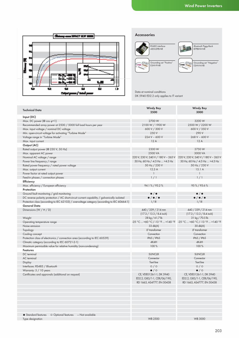
203
Wind Power Inverters
Input (DC)Max. DC power (@ cos ϕ=1)Recommended array power at 2500 / 5000 full load hours per yearMax. input voltage / nominal DC voltageMin. open-circuit voltage for activating ”Turbine Mode”Voltage range in ”Turbine Mode”Max. input currentOutput (AC)Rated output power (@ 230 V, 50 Hz)Max. apparent AC powerNominal AC voltage / rangePower line frequency / rangeRated power frequency / rated power voltageMax. output currentPower factor at rated output powerFeed-in phases / connection phasesEffi ciencyMax. effi ciency / European effi ciency ProtectionGround fault monitoring / grid monitoringDC reverse polarity protection / AC short-circuit current capability / galvanically isolatedProtection class (according to IEC 62103) / overvoltage category (according to IEC 60664-1) General DataDimensions (W / H / D)
WeightOperating temperature rangeNoise emissionTopologyCooling conceptProtection class of electronics / connection area (according to IEC 60529)Climatic category (according to IEC 60721-2-1)Maximum permissible value for relative humidity (non-condensing)FeaturesDC terminalAC terminalDisplayInterfaces: RS485 / BluetoothWarranty: 5 / 10 yearsCertifi cates and approvals (additional on request)
● Standard features ○ Optional features — Not availableType designation
2700 W2100 W / 1900 W
600 V / 300 V250 V
224 V – 600 V12 A
2300 W2500 VA
220 V, 230 V, 240 V / 180 V – 265 V50 Hz, 60 Hz / -4.5 Hz … +4.5 Hz
50 Hz / 230 V12.5 A
11 / 1
94.1 % / 93.2 %
● / ●● / ● / ●
I / III
440 / 339 / 214 mm(17.3 / 13.3 / 8.4 inch)
28 kg / 61,7 lb-25 °C … +60 °C / -13 °F … +140 °F
33 db(A)LF transformerConvectionIP65 / IP65
4K4H100 %
SUNCLIXConnectorText line○ / ○● / ○
CE, VDE0126-1-1, DK 5940 ED2.2, G83/1-1, CER/06/190, RD 1663, AS4777, EN 50438
WB 2500
3200 W2500 W / 2200 W
600 V / 350 V290 V
268 V – 600 V12 A
2750 W3000 VA
220 V, 230 V, 240 V / 180 V – 265 V50 Hz, 60 Hz / -4.5 Hz … +4.5 Hz
50 Hz / 230 V15.1 A
11 / 1
95 % / 93.6 %
● / ●● / ● / ●
I / III
440 / 339 / 214 mm(17.3 / 13.3 / 8.4 inch)
31 kg / 70.5 lb-25 °C … +60 °C / -13 °F … +140 °F
30 db(A)LF transformerConvectionIP65 / IP65
4K4H100 %
SUNCLIXConnectorText line○ / ○● / ○
CE, VDE0126-1-1, DK 5940 ED2.2, G83/1-1, CER/06/190, RD 1663, AS4777, EN 50438
WB 3000
Technical Data Windy Boy2500
Windy Boy3000
Data at nominal conditionsDK 5940 ED2.2 only applies to IT variant
Accessories
RS485 interface 485USPB-NR
Bluetooth Piggy-BackBTPBINV-NR
Grounding set ”Positive”ESHV-P-NR
Grounding set ”Negative”ESHV-N-NR
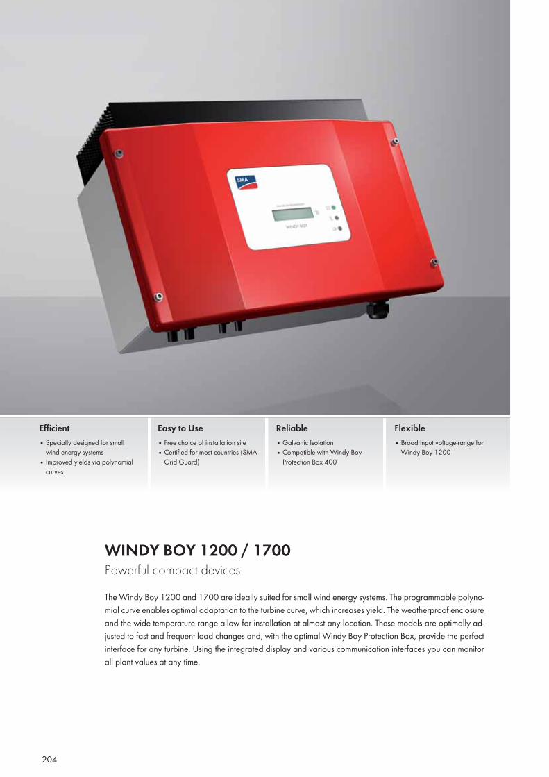
204
WINDY BOY 1200 / 1700 Powerful compact devicesThe Windy Boy 1200 and 1700 are ideally suited for small wind energy systems. The programmable polyno-mial curve enables optimal adaptation to the turbine curve, which increases yield. The weatherproof enclosure and the wide temperature range allow for installation at almost any location. These models are optimally ad-justed to fast and frequent load changes and, with the optimal Windy Boy Protection Box, provide the perfect interface for any turbine. Using the integrated display and various communication interfaces you can monitor all plant values at any time.
Efficient• Specially designed for small
wind energy systems• Improved yields via polynomial
curves
Easy to Use• Free choice of installation site• Certified for most countries (SMA
Grid Guard)
Reliable• Galvanic Isolation• Compatible with Windy Boy
Protection Box 400
Flexible• Broad input voltage-range for
Windy Boy 1200
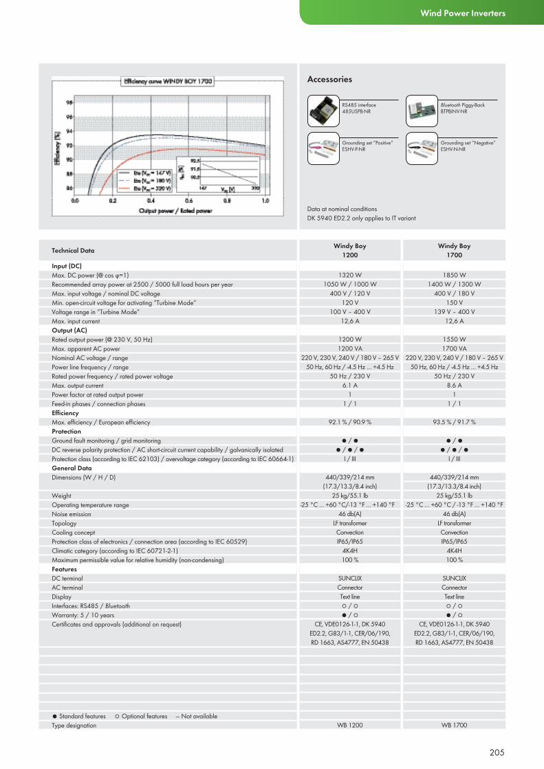
205
Wind Power Inverters
Input (DC)Max. DC power (@ cos ϕ=1)Recommended array power at 2500 / 5000 full load hours per yearMax. input voltage / nominal DC voltageMin. open-circuit voltage for activating ”Turbine Mode”Voltage range in ”Turbine Mode”Max. input currentOutput (AC)Rated output power (@ 230 V, 50 Hz)Max. apparent AC powerNominal AC voltage / rangePower line frequency / rangeRated power frequency / rated power voltageMax. output currentPower factor at rated output powerFeed-in phases / connection phasesEffi ciencyMax. effi ciency / European effi ciency ProtectionGround fault monitoring / grid monitoringDC reverse polarity protection / AC short-circuit current capability / galvanically isolatedProtection class (according to IEC 62103) / overvoltage category (according to IEC 60664-1) General DataDimensions (W / H / D)
WeightOperating temperature rangeNoise emissionTopologyCooling conceptProtection class of electronics / connection area (according to IEC 60529)Climatic category (according to IEC 60721-2-1)Maximum permissible value for relative humidity (non-condensing)FeaturesDC terminalAC terminalDisplayInterfaces: RS485 / BluetoothWarranty: 5 / 10 yearsCertifi cates and approvals (additional on request)
● Standard features ○ Optional features — Not availableType designation
1320 W1050 W / 1000 W
400 V / 120 V120 V
100 V – 400 V12,6 A
1200 W1200 VA
220 V, 230 V, 240 V / 180 V – 265 V50 Hz, 60 Hz / -4.5 Hz … +4.5 Hz
50 Hz / 230 V6.1 A
11 / 1
92.1 % / 90.9 %
● / ●● / ● / ●
I / III
440/339/214 mm(17.3/13.3/8.4 inch)
25 kg/55.1 lb-25 °C … +60 °C/-13 °F … +140 °F
46 db(A)LF transformerConvectionIP65/IP65
4K4H100 %
SUNCLIXConnectorText line○ / ○● / ○
CE, VDE0126-1-1, DK 5940 ED2.2, G83/1-1, CER/06/190, RD 1663, AS4777, EN 50438
WB 1200
1850 W1400 W / 1300 W
400 V / 180 V150 V
139 V – 400 V12,6 A
1550 W1700 VA
220 V, 230 V, 240 V / 180 V – 265 V50 Hz, 60 Hz / -4.5 Hz … +4.5 Hz
50 Hz / 230 V8.6 A
11 / 1
93.5 % / 91.7 %
● / ●● / ● / ●
I / III
440/339/214 mm(17.3/13.3/8.4 inch)
25 kg/55.1 lb-25 °C … +60 °C / -13 °F … +140 °F
46 db(A)LF transformerConvectionIP65/IP65
4K4H100 %
SUNCLIXConnectorText line○ / ○● / ○
CE, VDE0126-1-1, DK 5940 ED2.2, G83/1-1, CER/06/190, RD 1663, AS4777, EN 50438
WB 1700
Technical Data Windy Boy1200
Windy Boy1700
Data at nominal conditionsDK 5940 ED2.2 only applies to IT variant
Accessories
RS485 interface 485USPB-NR
Bluetooth Piggy-BackBTPBINV-NR
Grounding set ”Positive”ESHV-P-NR
Grounding set ”Negative”ESHV-N-NR

206
WINDY BOY 1100LV The solution for low generator voltageThe Windy Boy 1100LV is the perfect solution for the smallest wind energy systems with low generator voltage. Turbines with a nominal voltage of 24 or 48 V can be connected without an additional voltage converter. The programmable polynomial curve gives you full flexibility for choosing the turbine, while its weatherproof enclosure and wide operating temperature range allow for installation at nearly any location. As an inverter for wind energy systems, the Windy Boy is optimally adjusted to fast and frequent load changes. Its minimum internal consumption during periods of no wind also increases the yield, which you can monitor at any time using the display and various communication interfaces.
Economical• Specially designed for small
wind turbine systems• Outstanding performance
at low wind speeds
Easy to Use• Programmable polynomial curve
enables free selection of turbines• Free choice of installation site
Reliable• Galvanic isolation• In accordance with almost
all European power supply line guidelines
Secure• Worldwide SMA Service including
Serviceline• Comprehensive
SMA warranty program
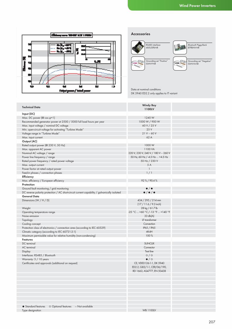
207
Wind Power Inverters
Input (DC)Max. DC power (@ cos ϕ=1)Recommended generator power at 2500 / 5000 full load hours per yearMax. input voltage / nominal DC voltageMin. open-circuit voltage for activating ”Turbine Mode”Voltage range in ”Turbine Mode”Max. input currentOutput (AC)Rated output power (@ 230 V, 50 Hz)Max. apparent AC powerNominal AC voltage / rangePower line frequency / rangeRated power frequency / rated power voltageMax. output currentPower factor at rated output powerFeed-in phases / connection phasesEffi ciencyMax. effi ciency / European effi ciency ProtectionGround fault monitoring / grid monitoringDC reverse polarity protection / AC short-circuit current capability / galvanically isolatedGeneral DataDimensions (W / H / D)
WeightOperating temperature rangeNoise emissionTopologyCooling conceptProtection class of electronics / connection area (according to IEC 60529)Climatic category (according to IEC 60721-2-1)Maximum permissible value for relative humidity (non-condensing)FeaturesDC terminalAC terminalDisplayInterfaces: RS485 / BluetoothWarranty: 5 / 10 yearsCertifi cates and approvals (additional on request)
● Standard features ○ Optional features — Not availableType designation
1240 W1000 W / 900 W
60 V / 25 V25 V
21 V – 60 V62 A
1000 W1100 VA
220 V, 230 V, 240 V / 180 V – 260 V50 Hz, 60 Hz / -4.5 Hz … +4.5 Hz
50 Hz / 230 V5 A1
1 / 1
92 % / 90.4 %
● / ●● / ● / ●
434 / 295 / 214 mm(17 / 11.6 / 9.3 inch)
28 kg / 61.7 lb-25 °C … +60 °C / -13 °F … +140 °F
33 db(A)LF transformerConvectionIP65 / IP65
4K4H100 %
SUNCLIXConnectorText line○ / ○● / ○
CE, VDE0126-1-1, DK 5940 ED2.2, G83/1-1, CER/06/190, RD 1663, AS4777, EN 50438
WB 1100LV
Technical Data Windy Boy1100LV
Data at nominal conditionsDK 5940 ED2.2 only applies to IT variant
Accessories
RS485 interface 485USPB-NR
Bluetooth Piggy-BackBTPBINV-NR
Grounding set ”Positive”ESHV-P-NR
Grounding set ”Negative”ESHV-N-NR
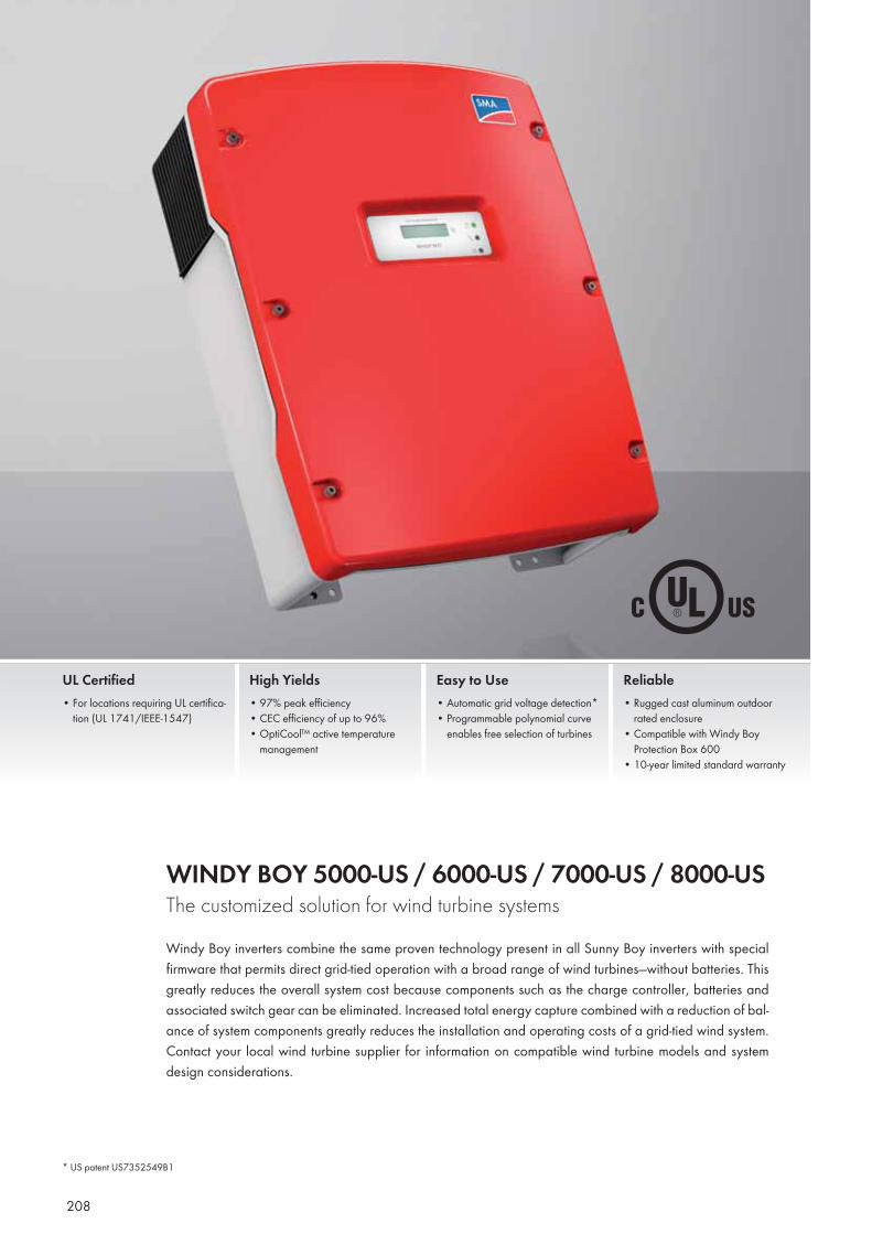
208
WINDY BOY 5000-US / 6000-US / 7000-US / 8000-US The customized solution for wind turbine systemsWindy Boy inverters combine the same proven technology present in all Sunny Boy inverters with special firmware that permits direct grid-tied operation with a broad range of wind turbines—without batteries. This greatly reduces the overall system cost because components such as the charge controller, batteries and associated switch gear can be eliminated. Increased total energy capture combined with a reduction of bal-ance of system components greatly reduces the installation and operating costs of a grid-tied wind system. Contact your local wind turbine supplier for information on compatible wind turbine models and system design considerations.
UL Certified• For locations requiring UL certifica-
tion (UL 1741/IEEE-1547)
High Yields• 97% peak efficiency• CEC efficiency of up to 96% • OptiCool™ active temperature
management
Easy to Use• Automatic grid voltage detection*• Programmable polynomial curve
enables free selection of turbines
Reliable• Rugged cast aluminum outdoor
rated enclosure• Compatible with Windy Boy
Protection Box 600• 10-year limited standard warranty
* US patent US7352549B1
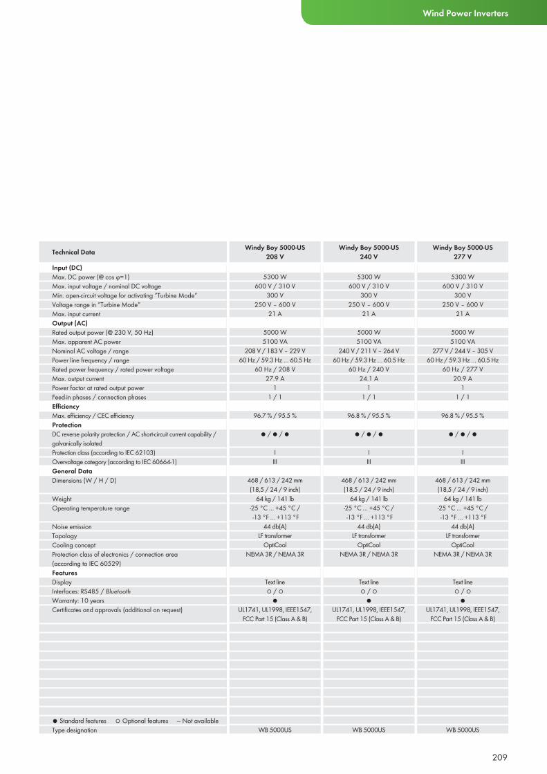
209
Wind Power Inverters
Input (DC)Max. DC power (@ cos ϕ=1)Max. input voltage / nominal DC voltageMin. open-circuit voltage for activating ”Turbine Mode”Voltage range in ”Turbine Mode”Max. input currentOutput (AC)Rated output power (@ 230 V, 50 Hz)Max. apparent AC powerNominal AC voltage / rangePower line frequency / rangeRated power frequency / rated power voltageMax. output currentPower factor at rated output powerFeed-in phases / connection phasesEffi ciencyMax. effi ciency / CEC effi ciencyProtectionDC reverse polarity protection / AC short-circuit current capability / galvanically isolatedProtection class (according to IEC 62103)Overvoltage category (according to IEC 60664-1) General DataDimensions (W / H / D)
WeightOperating temperature range
Noise emissionTopologyCooling conceptProtection class of electronics / connection area (according to IEC 60529)FeaturesDisplayInterfaces: RS485 / BluetoothWarranty: 10 yearsCertifi cates and approvals (additional on request)
● Standard features ○ Optional features — Not availableType designation
5300 W600 V / 310 V
300 V250 V – 600 V
21 A
5000 W5100 VA
208 V / 183 V – 229 V60 Hz / 59.3 Hz … 60.5 Hz
60 Hz / 208 V27.9 A
11 / 1
96.7 % / 95.5 %
● / ● / ●
IIII
468 / 613 / 242 mm(18,5 / 24 / 9 inch)
64 kg / 141 lb-25 °C … +45 °C / -13 °F … +113 °F
44 db(A)LF transformer
OptiCoolNEMA 3R / NEMA 3R
Text line○ / ○
●UL1741, UL1998, IEEE1547,
FCC Part 15 (Class A & B)
WB 5000US
5300 W600 V / 310 V
300 V250 V – 600 V
21 A
5000 W5100 VA
240 V / 211 V – 264 V60 Hz / 59.3 Hz … 60.5 Hz
60 Hz / 240 V24.1 A
11 / 1
96.8 % / 95.5 %
● / ● / ●
IIII
468 / 613 / 242 mm(18,5 / 24 / 9 inch)
64 kg / 141 lb-25 °C … +45 °C / -13 °F … +113 °F
44 db(A)LF transformer
OptiCoolNEMA 3R / NEMA 3R
Text line○ / ○
●UL1741, UL1998, IEEE1547,
FCC Part 15 (Class A & B)
WB 5000US
Technical Data Windy Boy 5000-US208 V
Windy Boy 5000-US240 V
5300 W600 V / 310 V
300 V250 V – 600 V
21 A
5000 W5100 VA
277 V / 244 V – 305 V60 Hz / 59.3 Hz … 60.5 Hz
60 Hz / 277 V20.9 A
11 / 1
96.8 % / 95.5 %
● / ● / ●
IIII
468 / 613 / 242 mm(18,5 / 24 / 9 inch)
64 kg / 141 lb-25 °C … +45 °C / -13 °F … +113 °F
44 db(A)LF transformer
OptiCoolNEMA 3R / NEMA 3R
Text line○ / ○
●UL1741, UL1998, IEEE1547,
FCC Part 15 (Class A & B)
WB 5000US
Windy Boy 5000-US277 V
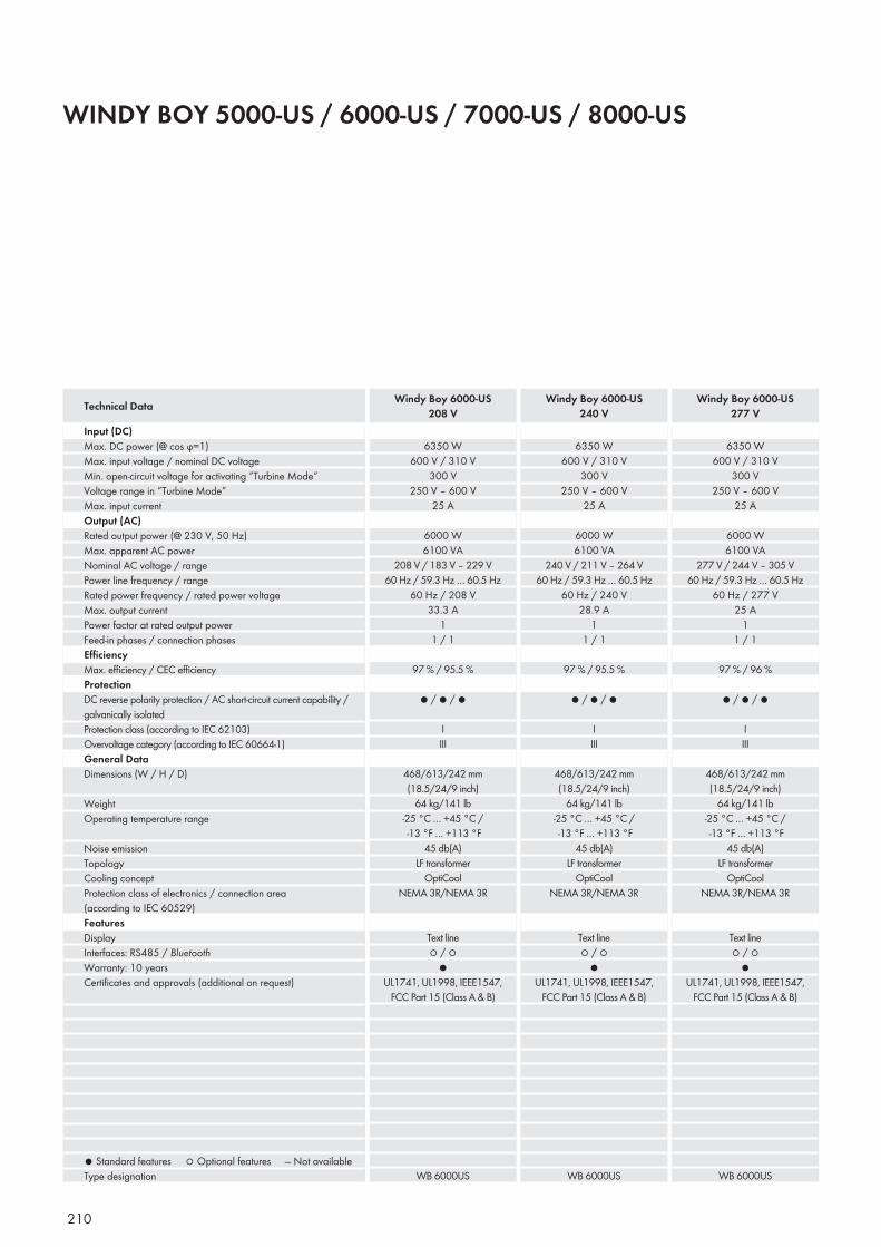
210
WINDY BOY 5000-US / 6000-US / 7000-US / 8000-US
Input (DC)Max. DC power (@ cos ϕ=1)Max. input voltage / nominal DC voltageMin. open-circuit voltage for activating ”Turbine Mode”Voltage range in ”Turbine Mode”Max. input currentOutput (AC)Rated output power (@ 230 V, 50 Hz)Max. apparent AC powerNominal AC voltage / rangePower line frequency / rangeRated power frequency / rated power voltageMax. output currentPower factor at rated output powerFeed-in phases / connection phasesEffi ciencyMax. effi ciency / CEC effi ciencyProtectionDC reverse polarity protection / AC short-circuit current capability / galvanically isolatedProtection class (according to IEC 62103)Overvoltage category (according to IEC 60664-1) General DataDimensions (W / H / D)
WeightOperating temperature range
Noise emissionTopologyCooling conceptProtection class of electronics / connection area (according to IEC 60529)FeaturesDisplayInterfaces: RS485 / BluetoothWarranty: 10 yearsCertifi cates and approvals (additional on request)
● Standard features ○ Optional features — Not availableType designation
Technical Data
6350 W600 V / 310 V
300 V250 V – 600 V
25 A
6000 W6100 VA
208 V / 183 V – 229 V60 Hz / 59.3 Hz … 60.5 Hz
60 Hz / 208 V33.3 A
11 / 1
97 % / 95.5 %
● / ● / ●
IIII
468/613/242 mm(18.5/24/9 inch)
64 kg/141 lb-25 °C … +45 °C / -13 °F … +113 °F
45 db(A)LF transformer
OptiCoolNEMA 3R/NEMA 3R
Text line○ / ○
●UL1741, UL1998, IEEE1547,
FCC Part 15 (Class A & B)
WB 6000US
6350 W600 V / 310 V
300 V250 V – 600 V
25 A
6000 W6100 VA
240 V / 211 V – 264 V60 Hz / 59.3 Hz … 60.5 Hz
60 Hz / 240 V28.9 A
11 / 1
97 % / 95.5 %
● / ● / ●
IIII
468/613/242 mm(18.5/24/9 inch)
64 kg/141 lb-25 °C … +45 °C / -13 °F … +113 °F
45 db(A)LF transformer
OptiCoolNEMA 3R/NEMA 3R
Text line○ / ○
●UL1741, UL1998, IEEE1547,
FCC Part 15 (Class A & B)
WB 6000US
Windy Boy 6000-US208 V
Windy Boy 6000-US240 V
6350 W600 V / 310 V
300 V250 V – 600 V
25 A
6000 W6100 VA
277 V / 244 V – 305 V60 Hz / 59.3 Hz … 60.5 Hz
60 Hz / 277 V25 A
11 / 1
97 % / 96 %
● / ● / ●
IIII
468/613/242 mm(18.5/24/9 inch)
64 kg/141 lb-25 °C … +45 °C / -13 °F … +113 °F
45 db(A)LF transformer
OptiCoolNEMA 3R/NEMA 3R
Text line○ / ○
●UL1741, UL1998, IEEE1547,
FCC Part 15 (Class A & B)
WB 6000US
Windy Boy 6000-US277 V
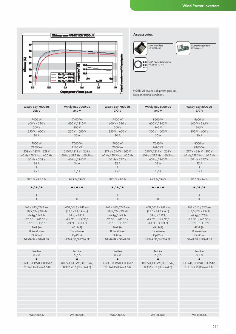
211
Wind Power Inverters
NOTE: US inverters ship with gray lids.Data at nominal conditions
Accessories
RS485 interface 485USPB-NR
Bluetooth Piggy-BackBTPBINV-NR
SMA Power Balancer SetPBL-SBUS-10-NR
7400 W600 V / 310 V
300 V250 V – 600 V
30 A
7000 W7100 VA
208 V / 183 V – 229 V60 Hz / 59.3 Hz … 60.5 Hz
60 Hz / 208 V34 A
11 / 1
97.1 % / 95.5 %
● / ● / ●
IIII
468 / 613 / 242 mm(18,5 / 24 / 9 inch)
64 kg / 141 lb-25 °C … +45 °C / -13 °F … +113 °F
46 db(A)LF transformer
OptiCoolNEMA 3R / NEMA 3R
Text line○ / ○
●UL1741, UL1998, IEEE1547,
FCC Part 15 (Class A & B)
WB 7000US
7400 W600 V / 310 V
300 V250 V – 600 V
30 A
7000 W7100 VA
240 V / 211 V – 264 V60 Hz / 59.3 Hz … 60.5 Hz
60 Hz / 240 V34 A
11 / 1
96.9 % / 96 %
● / ● / ●
IIII
468 / 613 / 242 mm(18,5 / 24 / 9 inch)
64 kg / 141 lb-25 °C … +45 °C / -13 °F … +113 °F
46 db(A)LF transformer
OptiCoolNEMA 3R / NEMA 3R
Text line○ / ○
●UL1741, UL1998, IEEE1547,
FCC Part 15 (Class A & B)
WB 7000US
Windy Boy 7000-US208 V
Windy Boy 7000-US240 V
7400 W600 V / 310 V
300 V250 V – 600 V
30 A
7000 W7100 VA
277 V / 244 V – 305 V60 Hz / 59.3 Hz … 60.5 Hz
60 Hz / 277 V32 A
11 / 1
97.1 % / 96 %
● / ● / ●
IIII
468 / 613 / 242 mm(18.5 / 24 / 9 inch)
64 kg / 141 lb-25 °C … +45 °C / -13 °F … +113 °F
46 db(A)LF transformer
OptiCoolNEMA 3R / NEMA 3R
Text line○ / ○
●UL1741, UL1998, IEEE1547,
FCC Part 15 (Class A & B)
WB 7000US
Windy Boy 7000-US277 V
8600 W600 V / 345 V
365 V300 V – 600 V
30 A
7680 W7680 VA
240 V / 211 V – 264 V60 Hz / 59.3 Hz … 60.5 Hz
60 Hz / 240 V32 A
11 / 1
96.3 % / 96 %
● / ● / ●
IIII
468 / 613 / 242 mm(18.5 / 24 / 9 inch)
69 kg / 152 lb-25 °C … +45 °C / -13 °F … +113 °F
49 db(A)LF transformer
OptiCoolNEMA 3R / NEMA 3R
Text line○ / ○
●UL1741, UL1998, IEEE1547,
FCC Part 15 (Class A & B)
WB 8000US
Windy Boy 8000-US240 V
8600 W600 V / 345 V
365 V300 V – 600 V
30 A
8000 W8100 VA
277 V / 244 V – 305 V60 Hz / 59.3 Hz … 60.5 Hz
60 Hz / 277 V32 A
11 / 1
96.5 % / 96 %
● / ● / ●
IIII
468 / 613 / 242 mm(18,5 / 24 / 9 inch)
69 kg / 152 lb-25 °C … +45 °C / -13 °F … +113 °F
49 db(A)LF transformer
OptiCoolNEMA 3R / NEMA 3R
Text line○ / ○
●UL1741, UL1998, IEEE1547,
FCC Part 15 (Class A & B)
WB 8000US
Windy Boy 8000-US277 V
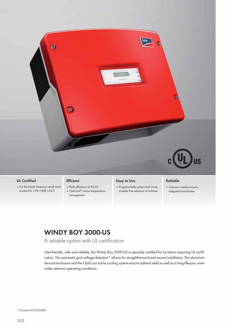
212
WINDY BOY 3000-US A reliable option with UL certificationUser-friendly, safe and reliable, the Windy Boy 3000-US is specially certified for locations requiring UL certifi-cation. The automatic grid voltage detection* allows for straightforward and secure installation. The aluminum die-cast enclosure and the OptiCool active cooling system ensure optimal yield as well as a long lifespan, even under adverse operating conditions.
UL Certified• For the North American small wind
market (UL 1741/IEEE-1547)
Efficient• Peak efficiency of 96.5%• OptiCool™ active temperature
management
Easy to Use• Programmable polynomial curve
enables free selection of turbines
Reliable• Galvanic isolation due to
integrated transformer
* US patent US7352549B1.
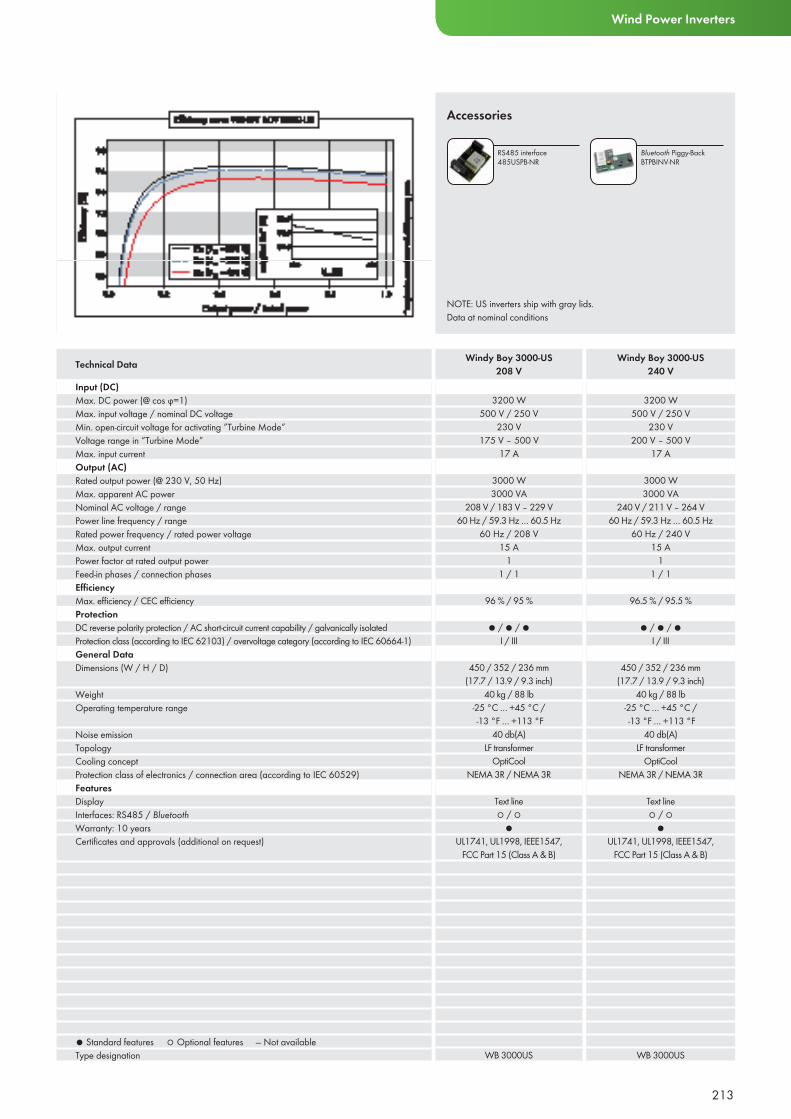
213
Wind Power Inverters
Input (DC)Max. DC power (@ cos ϕ=1)Max. input voltage / nominal DC voltageMin. open-circuit voltage for activating ”Turbine Mode”Voltage range in ”Turbine Mode”Max. input currentOutput (AC)Rated output power (@ 230 V, 50 Hz)Max. apparent AC powerNominal AC voltage / rangePower line frequency / rangeRated power frequency / rated power voltageMax. output currentPower factor at rated output powerFeed-in phases / connection phasesEffi ciencyMax. effi ciency / CEC effi ciencyProtectionDC reverse polarity protection / AC short-circuit current capability / galvanically isolatedProtection class (according to IEC 62103) / overvoltage category (according to IEC 60664-1) General DataDimensions (W / H / D)
WeightOperating temperature range
Noise emissionTopologyCooling conceptProtection class of electronics / connection area (according to IEC 60529)FeaturesDisplayInterfaces: RS485 / BluetoothWarranty: 10 yearsCertifi cates and approvals (additional on request)
● Standard features ○ Optional features — Not availableType designation
3200 W500 V / 250 V
230 V175 V – 500 V
17 A
3000 W3000 VA
208 V / 183 V – 229 V60 Hz / 59.3 Hz … 60.5 Hz
60 Hz / 208 V15 A
11 / 1
96 % / 95 %
● / ● / ●I / III
450 / 352 / 236 mm(17.7 / 13.9 / 9.3 inch)
40 kg / 88 lb-25 °C … +45 °C / -13 °F … +113 °F
40 db(A)LF transformer
OptiCoolNEMA 3R / NEMA 3R
Text line○ / ○
●UL1741, UL1998, IEEE1547,
FCC Part 15 (Class A & B)
WB 3000US
3200 W500 V / 250 V
230 V200 V – 500 V
17 A
3000 W3000 VA
240 V / 211 V – 264 V60 Hz / 59.3 Hz … 60.5 Hz
60 Hz / 240 V15 A
11 / 1
96.5 % / 95.5 %
● / ● / ●I / III
450 / 352 / 236 mm(17.7 / 13.9 / 9.3 inch)
40 kg / 88 lb-25 °C … +45 °C / -13 °F … +113 °F
40 db(A)LF transformer
OptiCoolNEMA 3R / NEMA 3R
Text line○ / ○
●UL1741, UL1998, IEEE1547,
FCC Part 15 (Class A & B)
WB 3000US
Technical Data Windy Boy 3000-US208 V
Windy Boy 3000-US240 V
NOTE: US inverters ship with gray lids.Data at nominal conditions
Accessories
RS485 interface 485USPB-NR
Bluetooth Piggy-BackBTPBINV-NR
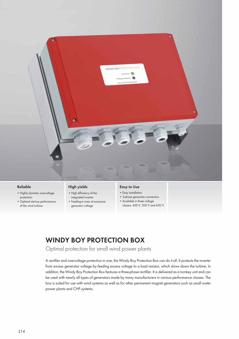
214
WINDY BOY PROTECTION BOX Optimal protection for small wind power plantsA rectifier and overvoltage protection in one, the Windy Boy Protection Box can do it all. It protects the inverter from excess generator voltage by feeding excess voltage to a load resistor, which slows down the turbine. In addition, the Windy Boy Protection Box features a three-phase rectifier. It is delivered as a turnkey unit and can be used with nearly all types of generators made by many manufacturers in various performance classes. The box is suited for use with wind systems as well as for other permanent magnet generators such as small water power plants and CHP systems.
Reliable• Highly dynamic overvoltage
protection• Optimal start-up performance
of the wind turbine
High yields• High efficiency of the
integrated inverter• Feeding-in even at excessive
generator voltage
Easy to Use• Easy installation• 3-phase generator connection• Available in three voltage
classes: 400 V, 500 V and 600 V
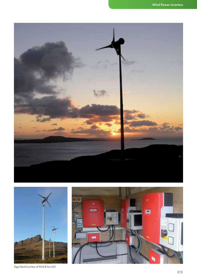
Eigg Island (courtesy of Wind & Sun Ltd.)
215
Wind Power Inverters
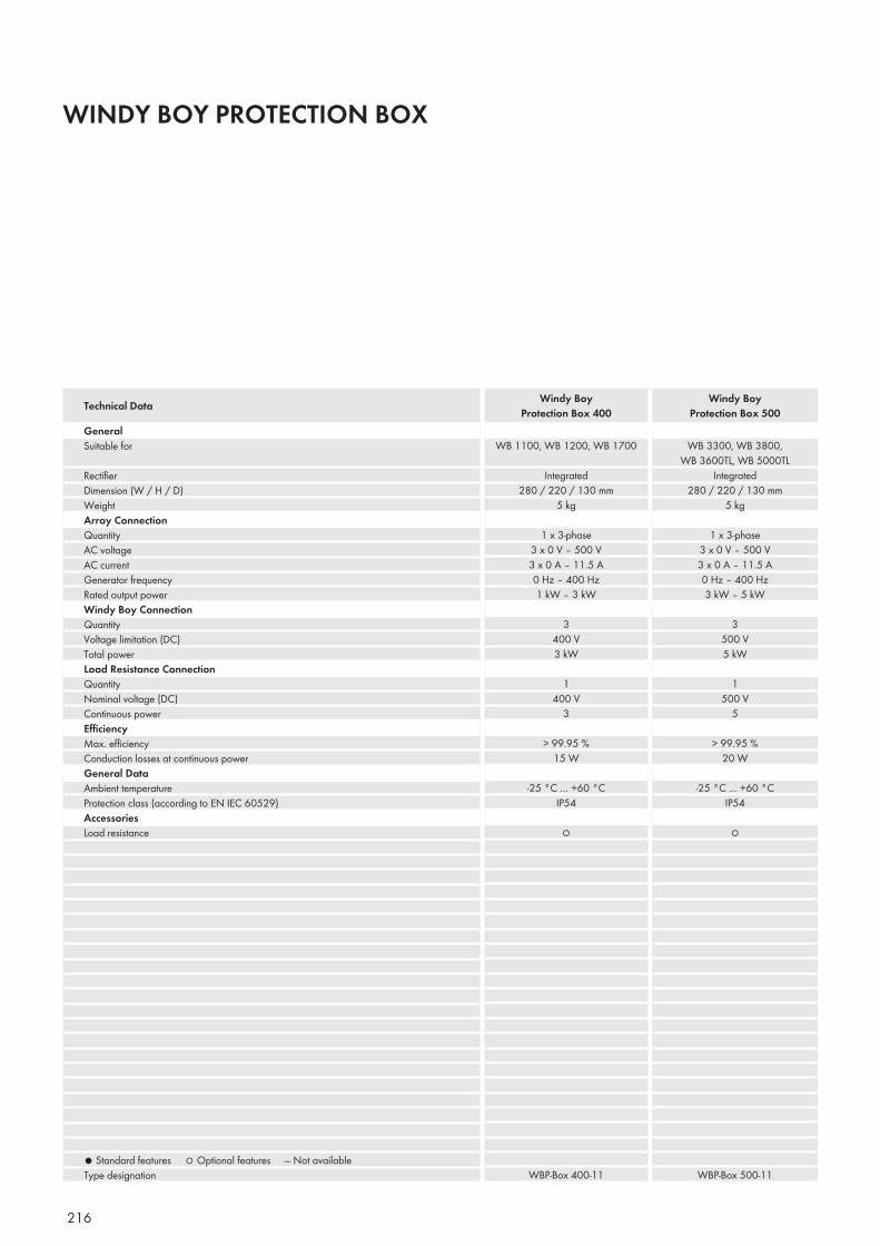
216
WINDY BOY PROTECTION BOX
GeneralSuitable for
Rectifi erDimension (W / H / D)WeightArray ConnectionQuantityAC voltageAC currentGenerator frequencyRated output powerWindy Boy ConnectionQuantityVoltage limitation (DC)Total powerLoad Resistance ConnectionQuantityNominal voltage (DC)Continuous powerEffi ciencyMax. effi ciencyConduction losses at continuous powerGeneral DataAmbient temperatureProtection class (according to EN IEC 60529)AccessoriesLoad resistance
● Standard features ○ Optional features — Not availableType designation
WB 1100, WB 1200, WB 1700
Integrated280 / 220 / 130 mm
5 kg
1 x 3-phase3 x 0 V – 500 V3 x 0 A – 11.5 A0 Hz – 400 Hz1 kW – 3 kW
3400 V3 kW
1400 V
3
> 99.95 %15 W
-25 °C … +60 °CIP54
○
WBP-Box 400-11
WB 3300, WB 3800, WB 3600TL, WB 5000TL
Integrated280 / 220 / 130 mm
5 kg
1 x 3-phase3 x 0 V – 500 V3 x 0 A – 11.5 A0 Hz – 400 Hz3 kW – 5 kW
3500 V5 kW
1500 V
5
> 99.95 %20 W
-25 °C … +60 °CIP54
○
WBP-Box 500-11
Technical Data Windy Boy Protection Box 400
Windy Boy Protection Box 500
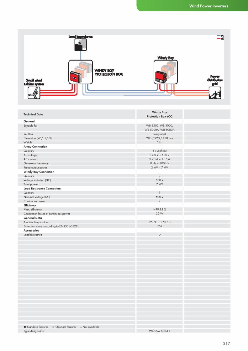
217
Wind Power Inverters
GeneralSuitable for
Rectifi erDimension (W / H / D)WeightArray ConnectionQuantityAC voltageAC currentGenerator frequencyRated output powerWindy Boy ConnectionQuantityVoltage limitation (DC)Total powerLoad Resistance ConnectionQuantityNominal voltage (DC)Continuous powerEffi ciencyMax. effi ciencyConduction losses at continuous powerGeneral DataAmbient temperatureProtection class (according to EN IEC 60529)AccessoriesLoad resistance
● Standard features ○ Optional features — Not availableType designation
WB 2500, WB 3000, WB 5000A, WB 6000A
Integrated280 / 220 / 130 mm
5 kg
1 x 3-phase3 x 0 V – 500 V3 x 0 A – 11.5 A0 Hz – 400 Hz2 kW – 7 kW
3600 V7 kW
1600 V
7
> 99.95 %30 W
-25 °C … +60 °CIP54
○
WBP-Box 600-11
Technical Data Windy Boy Protection Box 600
FUEL CELL INVERTERS
218
219
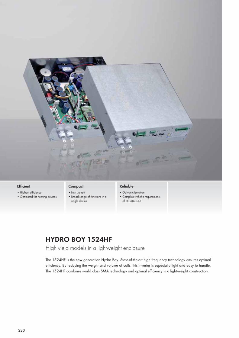
Custo
mer-ta
ilored
desig
n BAX
I INNO
TECH
220
HYDRO BOY 1524HFHigh yield models in a lightweight enclosureThe 1524HF is the new generation Hydro Boy. State-of-the-art high frequency technology ensures optimal efficiency. By reducing the weight and volume of coils, this inverter is especially light and easy to handle. The 1524HF combines world class SMA technology and optimal efficiency in a light-weight construction.
Efficient• Highest efficiency• Optimized for heating devices
Compact• Low weight• Broad range of functions in a
single device
Reliable• Galvanic isolation• Complies with the requirements
of EN 60335-1
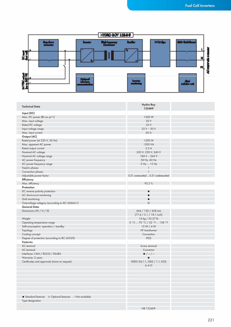
221
Fuel Cell Inverters
Input (DC)Max. DC power (@ cos ϕ=1)Max. input voltageRated DC voltageInput voltage rangeMax. input currentOutput (AC)Rated power (at 230 V, 50 Hz)Max. apparent AC powerRated output currentNominal AC voltageNominal AC voltage rangeAC power frequencyAC power frequency rangeFeed-in phasesConnection phasesAdjustable power factor Effi ciencyMax. effi ciencyProtectionDC reverse polarity protectionAC short-circuit monitoringGrid monitoringOvervoltage category (according to IEC 60664-1)General DataDimensions (W / H / D)
WeightOperating temperature rangeSelf-consumption: operation / standbyTopologyCooling conceptDegree of protection (according to IEC 60529) FeaturesDC terminalAC terminalInterfaces: CAN / RS232 / RS485Warranty: 2 yearsCertifi cates and approvals (more on request)
● Standard features ○ Optional features — Not availableType designation
1500 W50 V33 V
25 V – 50 V60 A
1200 W1200 VA
5.2 A220 V, 230 V, 240 V
184 V – 264 V50 Hz, 60 Hz-5 Hz … +5 Hz
11
0.51 overexcited ... 0.51 underexcited
92.2 %
●●●III
444 / 130 / 458 mm(77.4 / 5.1 / 18.1 inch)
16 kg / 35.27 lb0 °C … 70 °C / 32 °F … 158 °F
15 W / 4 WHF transformer
ConvectionIP20
Screw terminalConnector● / — / —
●VDE0126-1-1, G83 / 1-1, KGS
A 410
HB 1524HF
Technical Data Hydro Boy1524HF
222222

223
SERVICE
223
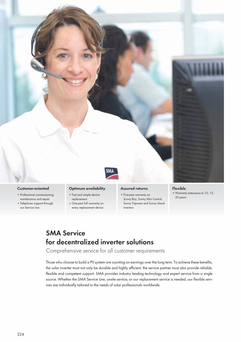
224
SMA Service for decentralized inverter solutionsComprehensive service for all customer requirementsThose who choose to build a PV system are counting on earnings over the long term. To achieve these benefits, the solar inverter must not only be durable and highly efficient, the service partner must also provide reliable, flexible and competent support. SMA provides industry leading technology and expert service from a single source. Whether the SMA Service Line, onsite service, or our replacement service is needed, our flexible serv-ices are individually tailored to the needs of solar professionals worldwide.
Customer-oriented• Professional commissioning,
maintenance and repair• Telephone support through
our Service Line
Optimum availability• Fast and simple device
replacement• One-year full warranty on
every replacement device
Assured returns• Five-year warranty on
Sunny Boy, Sunny Mini Central, Sunny Tripower and Sunny Island inverters
Flexible• Warranty extensions to 10, 15,
20 years
225
Expert advice over the telephone via the SMA Service Line
The experts on our Service Line support solar professionals during the installation and commissioning of PV plants, advise on technical issues, and provide tips on system monitoring. These specially trained expert teams are available at various telephone numbers for all inquiries regarding invert-ers, communication devices, and Sunny Island products.
SMA Service on-site
Solar professionals can rely on our sup-port. We have a well developed interna-tional service network with numerous ac-cess points, currently in 13 countries. In the event of a service requirement, SMA can be onsite quickly. We are ready to support our customers around the world, from onsite diagnosis to device replacement.
Device replacement for highest security of return
Should a failure occur, we will keep down times as short as possible by replacing your device. After a call is received, the replace-ment inverter is generally shipped on the same day. To replace the defective inverter, the customer will receive a comparable de-vice with state-of-the-art technology, includ-ing all updates and alterations. If a device is exchanged within the warranty period, the remaining warranty period is transferred to the replacement device. In any event, we provide a one-year full warranty on all re-placement parts both within and outside the warranty period, and that’s not all. Our serv-ice technicians can take care of the installa-tion of the replacement device upon request.
More security with long-term warranties
SMA products meet the highest quality standards and come with a standard five year warranty. Additionally, we offer an extended warranty for an additional 5, 10, 15 or 20 years, with which operators can assure themselves of the right to free repair or a replacement device.
Interested?
Whether for commissioning, service work or tips on plant monitoring, operators and solar professionals are in good hands with SMA Service. Additional information on our services is available on the corresponding SMA website, where you may also down-load or order a free copy of our service data sheet.
Service
SMA Solar Technology AG, Germany > Inverter +49 561 9522-1499> Communication +49 561 9522-2499> SMS call-back +49 176 888 222 44
SMA America, LLCTel. +1 916 625 0870Tel. 877 MY SMATech (877-697-6283)
SMA Technology Australia Pty. Ltd.Tel. +61 2 9669 2889 Tel. 1800 SMA AUS (1800 762 287)
SMA Beijing Commercial Company Ltd.Tel. +86 10 5150 1685-602
SMA Benelux BVBA/SPRLTel. +32 15 286730
SMA Czech Republic s. r. o. Tel. +420 235 010 417
SMA France S.A.S.Sunny Boy / Sunny Mini Central Tel. +33 (0)4 72 09 04 40Surveillance et Communication Tel. +33 (0)4 72 09 04 41
SMA Hellas AETel. +30 210 9856 666
SMA Ibérica Tecnología Solar, S.L.Tel. +34 900 14 22 22
SMA Italia S.r.l.Tel. +39 02 8934 7299
SMA Technology Korea Co., Ltd.Tel. +82 2 508 8599
SMA Portugal, Niestetal ServicesTel. +351 21 2387860
SMA Middle East LLCTel. +971 2 698 5080Masdar City, Abu Dhabi (AE)
SMA SOLAR TECHNOLOGY AG WWW.SMA-SOLAR.COM
SMA SERVICELINES
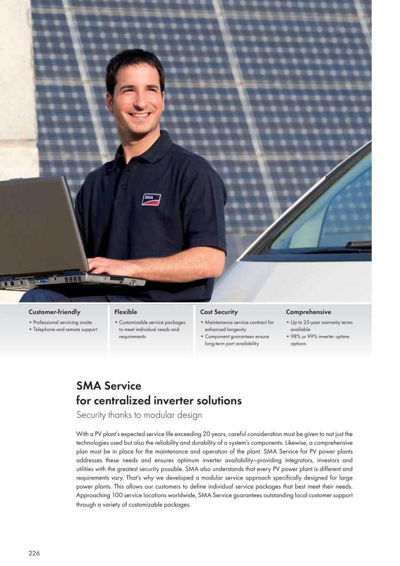
226
SMA Service for centralized inverter solutionsSecurity thanks to modular designWith a PV plant’s expected service life exceeding 20 years, careful consideration must be given to not just the technologies used but also the reliability and durability of a system’s components. Likewise, a comprehensive plan must be in place for the maintenance and operation of the plant. SMA Service for PV power plants addresses these needs and ensures optimum inverter availability—providing integrators, investors and utilities with the greatest security possible. SMA also understands that every PV power plant is different and requirements vary. That’s why we developed a modular service approach specifi cally designed for large power plants. This allows our customers to defi ne individual service packages that best meet their needs. Approaching 100 service locations worldwide, SMA Service guarantees outstanding local customer support through a variety of customizable packages.
Customer-friendly• Professional servicing onsite• Telephone and remote support
Flexible• Customizable service packages to meet individual needs and requirements
Cost Security• Maintenance service contract for enhanced longevity • Component guarantees ensure long-term part availability
Comprehensive• Up to 25-year warranty terms available• 98% or 99% inverter uptime options
227
Maintenance
To optimize system performance, SMA performs controls, cleaning and parts replacement at regular intervals. This preventative maintenance is important for long term operation.
Spare parts warranty
Whether electronic or mechanical, we guarantee the availability of all components over the duration of the complete system life cycle. Our customers can be confi dent that even as technologies evolve, SMA’s support will be constant. This guarantee also provides additional cost security for the operational life of the inverter solution.
Diagnostics and repair
Beginning with remote service, which often eliminates on-site assistance, to First Level, (diagnostics and small repairs), or Second Level Support, (comprehensive repairs), SMA offers the proper service plan for our customers’ needs. Customers can optionally administer First Level Support themselves. With local staff to assist, SMA Service quickly provides the appropriate response to any situation.
Inverter availability
SMA inverters lead the industry. Our customers know our world-class manufacturing and high-quality components result in a superior solution. To fully protect investment security, SMA offers two inverter uptime guarantees: 98 or 99 percent. With these guarantees, we will reimburse the customer for the difference between the actual and agreed-upon inverter uptime. With warranty periods up to 25 years in length, SMA can also guarantee our solution’s performance for the life of the PV plant.
Need more information?
Call SMA Power Plant Solutions at +1 888 476 2872 to hear more.
Service
SMA Solar Technology AG, Germany Tel. +49 561 9522 299
SMA America, LLCTel. +1 916 625 0870Tel. 877 MY SMATech (877-697-6283)
SMA Technology Australia Pty. Ltd.Tel. +61 2 9669 2889 Tel. 1800 SMA AUS (1800 762 287)
SMA Beijing Commercial Company Ltd.Tel. +86 10 51501685-602
SMA Benelux BVBA/SPRLTel: +32 15 286 730
SMA Czech Republic s. r. o. Tel. +420 235 010 417
SMA France S.A.S.Tel. +33 472 09 04 43
SMA Hellas AETel. +30 210 9856 666
SMA Ibérica Tecnología Solar, S.L.Tel. +34 900 14 22 22
SMA Italia S.r.l.Tel. +39 0289347 -299
SMA Technology Korea Co., Ltd.Tel. +82 2 508 8599
SMA Portugal, Niestetal ServicesTel. +351 2 12 38 78 60
SMA Middle East LLCTel. +971 2 698 5080Masdar City, Abu Dhabi (AE)
SMA SOLAR TECHNOLOGY AG WWW.SMA-SOLAR.COM
SMA SERVICELINES

228
229
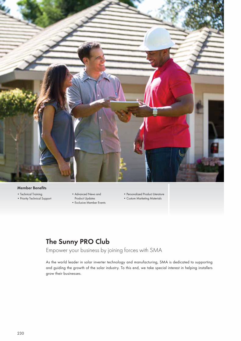
230
The Sunny PRO Club Empower your business by joining forces with SMAAs the world leader in solar inverter technology and manufacturing, SMA is dedicated to supporting and guiding the growth of the solar industry. To this end, we take special interest in helping installers grow their businesses.
• Advanced News and Product Updates• Exclusive Member Events
• Personalized Product Literature• Custom Marketing Materials
Member Benefits• Technical Training• Priority Technical Support

231
Join Today!
It’s easy to become a Sunny PRO Club member! Simply download your at www.SunnyPROClub.com. Once your applicati-on is processed, you’ll receive a compre-hensive welcome package outlining the details of our membership.
Membership Requirements:
• Annual membership fee: $175.00• Maintain a licensed electrician or NABCEP certified installer on staff• Attend 1 Technical Training per year
We look forward to partnering with you!
Sunny PRO ClubTel. +1 877 506 1747 [email protected] www.SunnyPROClub.com
A Professional Partnership
Whether you’re a two-person start-up or a nationwide operation, success doesn’t come easy. That’s why you need strong partners. By joining SMA’s Sunny PRO Club, you gain access to a host of valuable services designed to support your business. From customizable marketing tools to ad-vanced technical training, let SMA give you the confidence you need to work to your full potential.
Technical Benefits
As a Sunny PRO Club member, you will have the technical resources you need to be successful in this competitive market. Po-sition your company as an SMA Solar Po-wer Professional and give your business the edge it needs to surpass the competition.
Stay informed on new technologies, products and installation best-practices through:
• Free & Discounted Solar Academy Training• Exclusive Technical Webinars
• Priority Technical Support • Advanced News & Product Updates• Invites to Member Events
Marketing Services
Sunny PRO Club members gain instant ac-cess to a catalog of Marketing Services specially designed to support their busines-ses. By combining your expertise with the strength of the SMA brand and resources, you will be poised to take your business to the next level.
Take advantage of a broad selection of marketing materials including:
• Personalized Brochures• Tradeshow Displays• Advertising Templates• Logo Design Services• Personalized Product Literature• Custom Mailers• Vehicle Signage
Sunny PRO Club

232

233
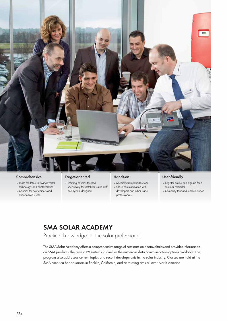
234
Comprehensive• Learn the latest in SMA inverter
technology and photovoltaics• Courses for new-comers and
experienced users
Target-oriented• Training courses tailored
specifically for installers, sales staff and system designers
Hands-on• Specially-trained instructors• Close communication with
developers and other trade professionals
User-friendly• Register online and sign up for a
seminar reminder• Company tour and lunch included
SMA SOLAR ACADEMY Practical knowledge for the solar professionalThe SMA Solar Academy offers a comprehensive range of seminars on photovoltaics and provides information on SMA products, their use in PV systems, as well as the numerous data communication options available. The program also addresses current topics and recent developments in the solar industry. Classes are held at the SMA America headquarters in Rocklin, California, and at rotating sites all over North America.
235
SMA Solar Academy
Training courses(Each seminar is one day in duration and can be booked individually.)INTRODUCTION TO PHOTOVOLTAICS This course offers a basic understanding of electricity and electronics as it relates to photovoltaics. Topics include basic understanding of AC and DC circuits, AC and DC electrical components, photovoltaic cell, module and array parameters, utility transformers and electrical safety.
MINI SEMINAR This short seminar focuses on a technical overview of Sunny Boy inverters and their interaction with the utility grid. Topics include grid-tied photovoltaic components, inverter MPP tracking characteristics, single phase and three phase utility applications, SMA DC disconnect and inverter installation and troubleshooting. This seminar also provides an introduction to the Sunny Central series of inverters.
SALES & MARKETING TRAINING* The focus of this training centers on the effective marketing and sales of SMA products to grow your business. Topics include product features and benefi ts, current product line, product comparisons, the economics of selling solar and in depth product knowledge.
SUNNY BOY 1 This course offers a basic understanding of Sunny Boy inverters and their interaction with the utility grid. Topics include Sunny Boy product knowledge, U.S. utility transformer integration, SMA DC disconnect, components of grid-tied PV systems, residential grid-tied backup, inverter safeguards and UL1741. It also covers installation requirements based on the National Electrical Code and introduces safe installation practices for high DC and AC voltages. Hands on training provides reinforcement of training concepts.
SUNNY BOY 2 This is an advanced-level course on multiple Sunny Boy interters and Sunny Tower installations in three phase. Topics include the design and sizing of the PV array using Sunny Design software, sizing of DC and AC over-current protection devices, as well as wiring to comply with UL and the National Electrical Code safety standards. Hands on training provides reinforcement of training concepts.
SUNNY CENTRAL 1 This course provides in-depth knowledge of the Sunny Central family of inverters with and without internal transformers. Applications include large-scale PV plants ranging from hundreds of kilowatts to utility scale megawatt installations. This training session provides an overview of the National Electrical Code requirements and safety in dealing with high voltages. It also provides a broad perspective of data logging, monitoring, command and control options for interaction with plant operators and utilities.
SUNNY CENTRAL 2 This course provides advanced-level training on central inverters for utility scale applications. The curriculum focuses on the design, installation and monitoring of PV plants in the megawatt range. It reviews features and functionalities of central inverters, with internal and external transformers, connected to low- and medium-voltage grids. The seminar also provides an overview of grid management features that allow utilities to remotely control PV plants.
SUNNY ISLAND 1 This course provides an in-depth understanding of the Sunny Island battery backup inverter, its response to a grid failure and its role in a grid-tied backup system. Topics include battery management, battery types, generator management, generator types, system management and additional system components, system design. Hands on training provides reinforcement of training concepts.
SUNNY ISLAND 2 This course provides a review of grid-tied backup systems using AC and DC coupled energy sources and a hands-on practice on battery, generator, grid, and system management confi guration. It also covers design, installation, and troubleshooting guidelines for single phase and three phase off-grid systems with an overview of system diagnostic codes.
COMMUNICATION 1 This course provides an overview of inverter communication options including displays, user interfaces, data logging, monitoring and control of renewable energy plants. Topics include RS-232, RS-485, wired and wireless hardware and communication protocol standards. The course includes an introduction to data logging using WebBox, Sunny Beam and SMA software for single and multiple inverters.
REVENUE GRADE METERING* This course provides an introduction to power measurment, modbus command and control as well as demand monitoring options for large photovoltaic plants. It also provides an in-depth look at SMA’s Power Measurement Kit, a solution for applications where ANSI C12 revenue-grade metering is required for production based incentive (PBI) markets.
WEBBOX This course provides an in-depth look at the installation and setup of the WebBox, an SMA data logging and monitoring system. This session focuses on wiring and confi guring the WebBox to monitor single and multiple SMA inverters locally and over the Internet. Attendees will also learn how to register the WebBox to the Sunny Portal to post and customize renewable energy plant web pages.
*Does not qualify for NABCEP credit
SeminarsSMA Solar Academy in Rocklin, California, offers 12 seminars on photovoltaic systems and sales, most of which qualify for NABCEP (North American Board Certified Energy Practitioners) continuing education credit. The curriculum consists of a broad range of classes covering grid-tied and off-grid products, commercial systems, communication devices, sales and marketing, code compliance and installation best practices. Each course is designed to meet the demands of increasingly complex industry requirements and provide a level of technical detail sufficient for both beginners and experienced professionals.
» Interested? Registering for seminars at the SMA Solar Academy is simple. Just visit www.SMA-America.com/SolarAcademy to view course schedules and
locations. Register by phone at +1 916 625 0870 or send an e-mail to [email protected]. We look forward to seeing you at one of our seminars soon.

236

237
KNOW-HOW
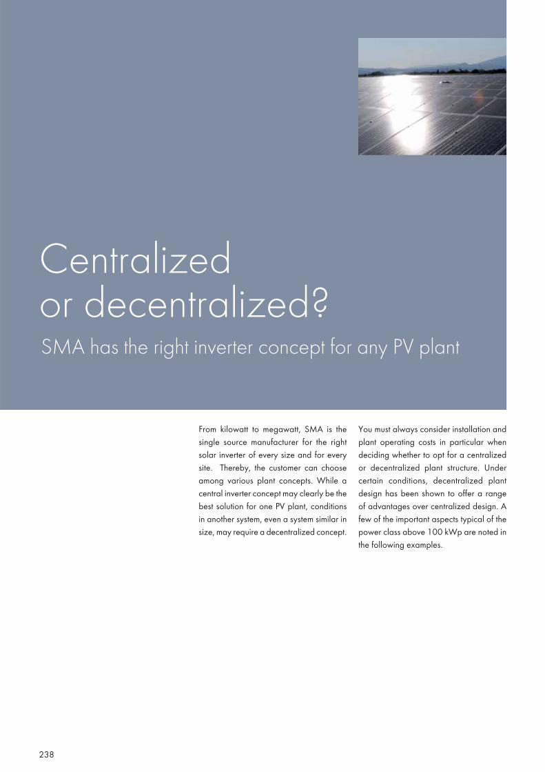
238
From kilowatt to megawatt, SMA is the single source manufacturer for the right solar inverter of every size and for every site. Thereby, the customer can choose among various plant concepts. While a central inverter concept may clearly be the best solution for one PV plant, conditions in another system, even a system similar in size, may require a decentralized concept.
You must always consider installation and plant operating costs in particular when deciding whether to opt for a centralized or decentralized plant structure. Under certain conditions, decentralized plant design has been shown to offer a range of advantages over centralized design. A few of the important aspects typical of the power class above 100 kWp are noted in the following examples.
Centralized or decentralized? SMA has the right inverter concept for any PV plant
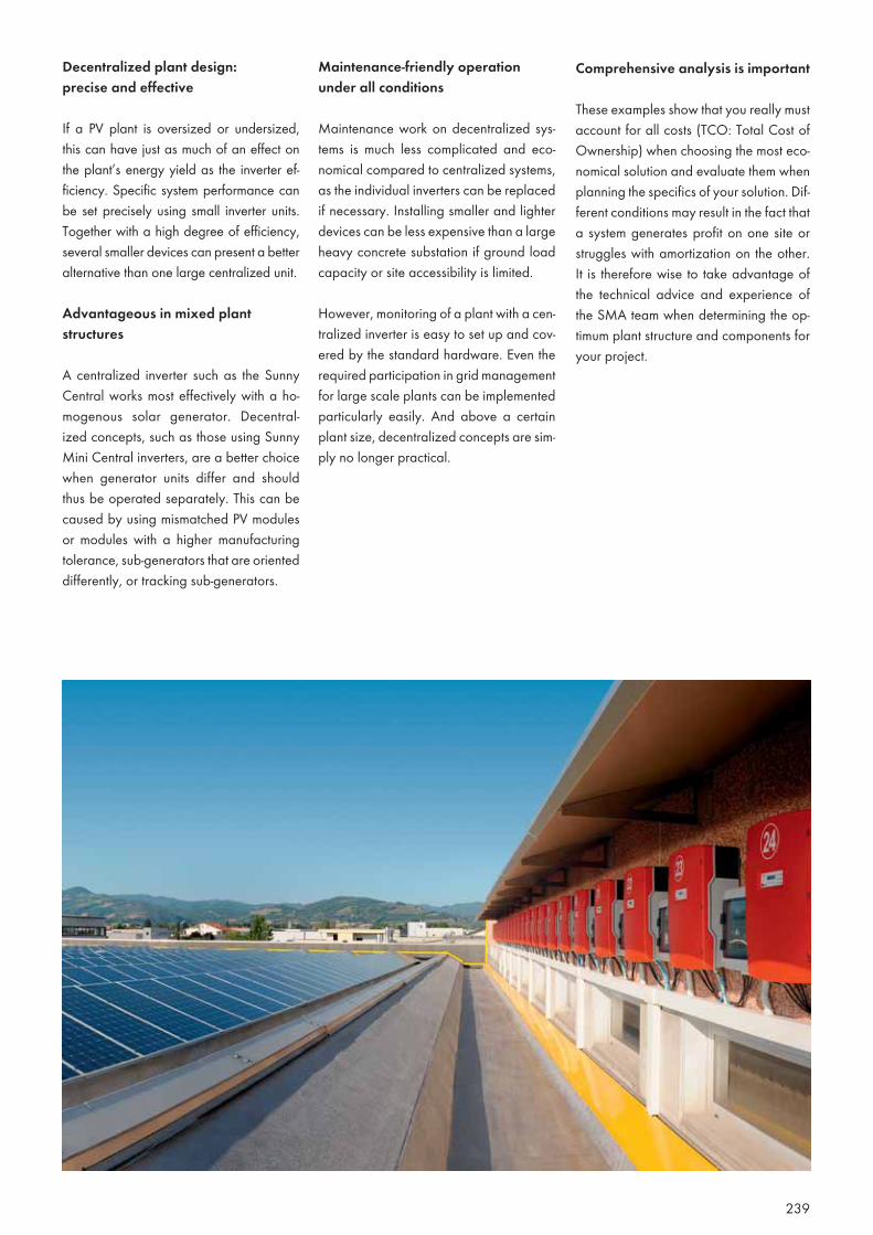
239
Decentralized plant design: precise and effective
If a PV plant is oversized or undersized, this can have just as much of an effect on the plant’s energy yield as the inverter ef-ficiency. Specific system performance can be set precisely using small inverter units. Together with a high degree of efficiency, several smaller devices can present a better alternative than one large centralized unit.
Advantageous in mixed plant structures
A centralized inverter such as the Sunny Central works most effectively with a ho-mogenous solar generator. Decentral-ized concepts, such as those using Sunny Mini Central inverters, are a better choice when generator units differ and should thus be operated separately. This can be caused by using mismatched PV modules or modules with a higher manufacturing tolerance, sub-generators that are oriented differently, or tracking sub-generators.
Maintenance-friendly operation under all conditions
Maintenance work on decentralized sys-tems is much less complicated and eco-nomical compared to centralized systems, as the individual inverters can be replaced if necessary. Installing smaller and lighter devices can be less expensive than a large heavy concrete substation if ground load capacity or site accessibility is limited.
However, monitoring of a plant with a cen-tralized inverter is easy to set up and cov-ered by the standard hardware. Even the required participation in grid management for large scale plants can be implemented particularly easily. And above a certain plant size, decentralized concepts are sim-ply no longer practical.
Comprehensive analysis is important
These examples show that you really must account for all costs (TCO: Total Cost of Ownership) when choosing the most eco-nomical solution and evaluate them when planning the specifics of your solution. Dif-ferent conditions may result in the fact that a system generates profit on one site or struggles with amortization on the other. It is therefore wise to take advantage of the technical advice and experience of the SMA team when determining the op-timum plant structure and components for your project.
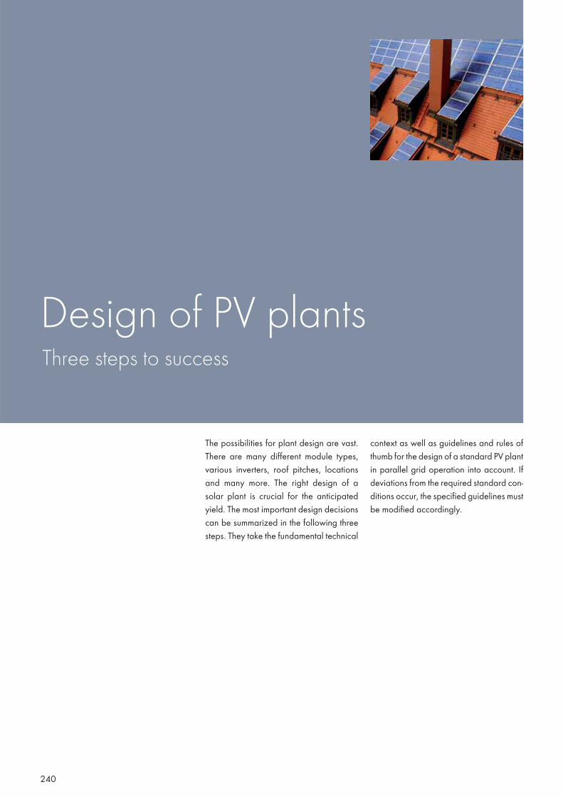
240
The possibilities for plant design are vast. There are many different module types, various inverters, roof pitches, locations and many more. The right design of a solar plant is crucial for the anticipated yield. The most important design decisions can be summarized in the following three steps. They take the fundamental technical
context as well as guidelines and rules of thumb for the design of a standard PV plant in parallel grid operation into account. If deviations from the required standard con-ditions occur, the specified guidelines must be modified accordingly.
Design of PV plants Three steps to success
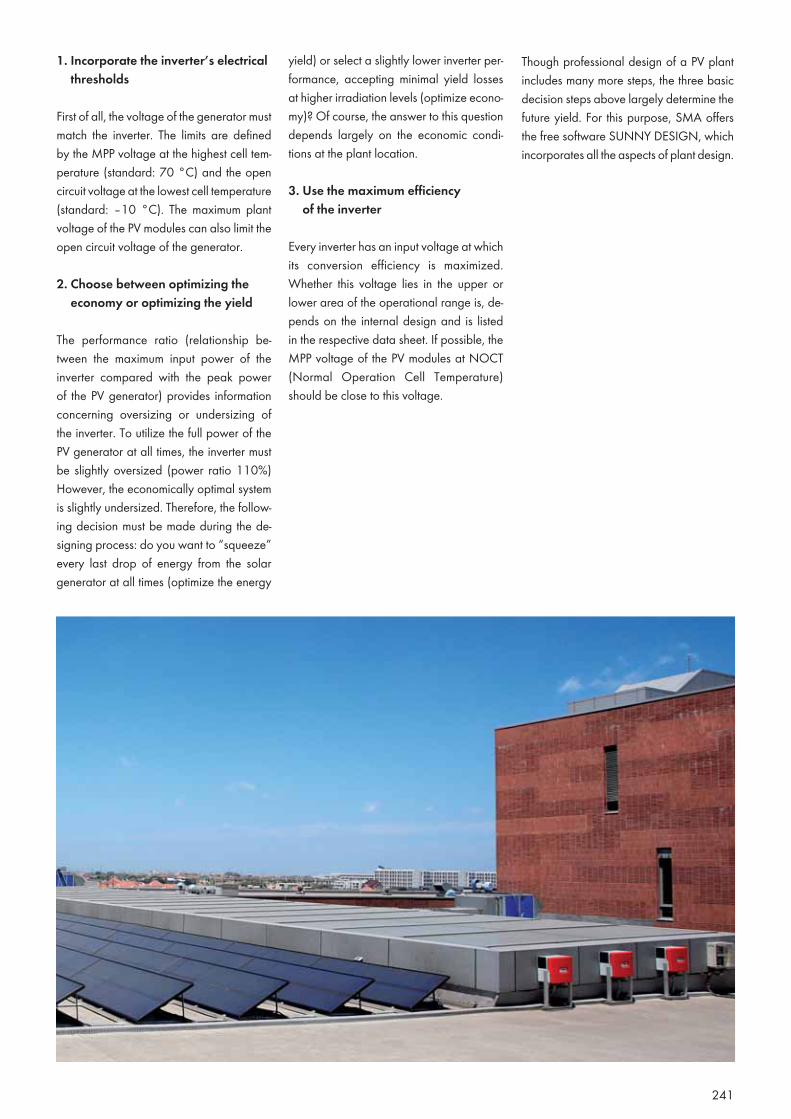
241
1. Incorporate the inverter’s electrical thresholds
First of all, the voltage of the generator must match the inverter. The limits are defined by the MPP voltage at the highest cell tem-perature (standard: 70 °C) and the open circuit voltage at the lowest cell temperature (standard: –10 °C). The maximum plant voltage of the PV modules can also limit the open circuit voltage of the generator.
2. Choose between optimizing the economy or optimizing the yield
The performance ratio (relationship be-tween the maximum input power of the inverter compared with the peak power of the PV generator) provides information concerning oversizing or undersizing of the inverter. To utilize the full power of the PV generator at all times, the inverter must be slightly oversized (power ratio 110%) However, the economically optimal system is slightly undersized. Therefore, the follow-ing decision must be made during the de-signing process: do you want to “squeeze” every last drop of energy from the solar generator at all times (optimize the energy
yield) or select a slightly lower inverter per-formance, accepting minimal yield losses at higher irradiation levels (optimize econo-my)? Of course, the answer to this question depends largely on the economic condi-tions at the plant location.
3. Use the maximum efficiency of the inverter
Every inverter has an input voltage at which its conversion efficiency is maximized. Whether this voltage lies in the upper or lower area of the operational range is, de-pends on the internal design and is listed in the respective data sheet. If possible, the MPP voltage of the PV modules at NOCT (Normal Operation Cell Temperature) should be close to this voltage.
Though professional design of a PV plant includes many more steps, the three basic decision steps above largely determine the future yield. For this purpose, SMA offers the free software SUNNY DESIGN, which incorporates all the aspects of plant design.
242
It started in Germany in January 2009, fol-lowing France in 2008: since then, large-scale PV plants have had to participate in grid management, and provide grid services to an increasing extent. Experts unanimously agree that such measures are essential. The installed PV power increases continuously, and individual projects are growing larger and larger. Increasing size and power also mean greater responsibility for the electricity grid, as only a stable grid permits unrestricted expansion of renew-able energies. This was enough reason for SMA to commit fully to participation from the outset. SMA, technology leader in the field of solar inverters, is now also a pioneer in grid management.
Powerful grid management functions
For example, the SMA Power Reducer Box was the first market ready solution for utility interaction management as defined in Art. 6 of the German Renewable Energies Act (EEG)—and is also compatible with virtually all SMA inverters. Inverters with an auto-matic power reduction feature in case of increased frequencies make a valuable con-tribution to stabilizing the grid frequency if more energy is generated than can be con-sumed. Reactive-power compatible invert-ers help keep the grid voltage constant, but can also be used to compensate for undesir-able phase shifts. And the dynamic grid sup-port features support the grid in the event of faults, and can also prevent, or at least restrict, the fault from spreading further.
Inverters as grid managersOverview of the grid management functions of SMA inverters
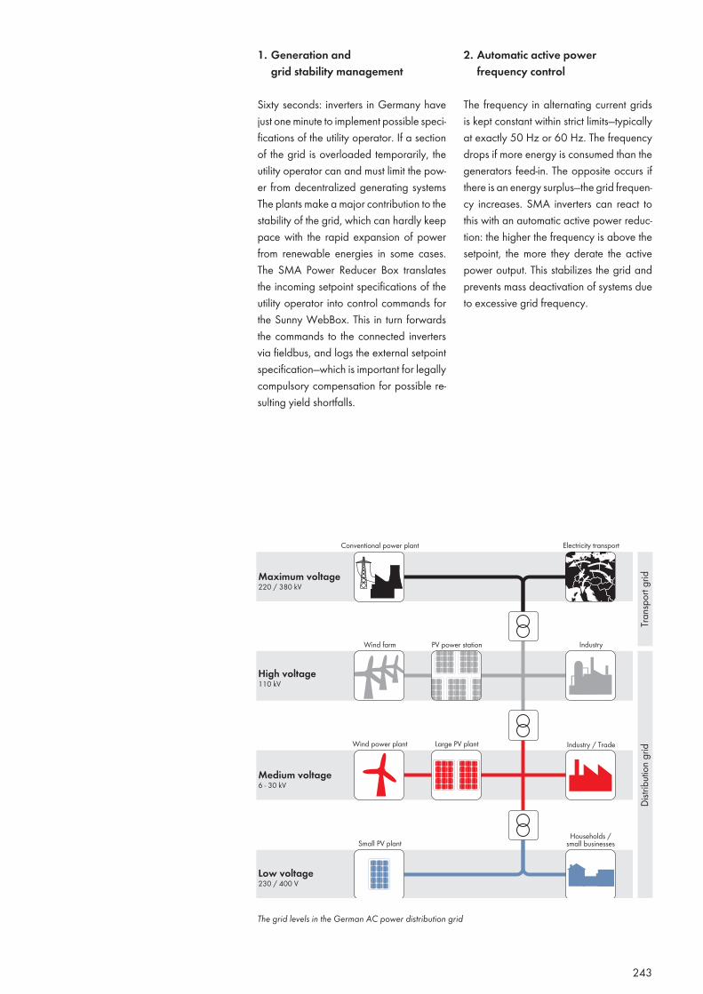
243
1. Generation and grid stability management
Sixty seconds: inverters in Germany have just one minute to implement possible speci-fications of the utility operator. If a section of the grid is overloaded temporarily, the utility operator can and must limit the pow-er from decentralized generating systems The plants make a major contribution to the stability of the grid, which can hardly keep pace with the rapid expansion of power from renewable energies in some cases. The SMA Power Reducer Box translates the incoming setpoint specifications of the utility operator into control commands for the Sunny WebBox. This in turn forwards the commands to the connected inverters via fieldbus, and logs the external setpoint specification—which is important for legally compulsory compensation for possible re-sulting yield shortfalls.
2. Automatic active powerfrequency control
The frequency in alternating current grids is kept constant within strict limits—typically at exactly 50 Hz or 60 Hz. The frequency drops if more energy is consumed than the generators feed-in. The opposite occurs if there is an energy surplus—the grid frequen-cy increases. SMA inverters can react to this with an automatic active power reduc-tion: the higher the frequency is above the setpoint, the more they derate the active power output. This stabilizes the grid and prevents mass deactivation of systems due to excessive grid frequency.
The grid levels in the German AC power distribution grid
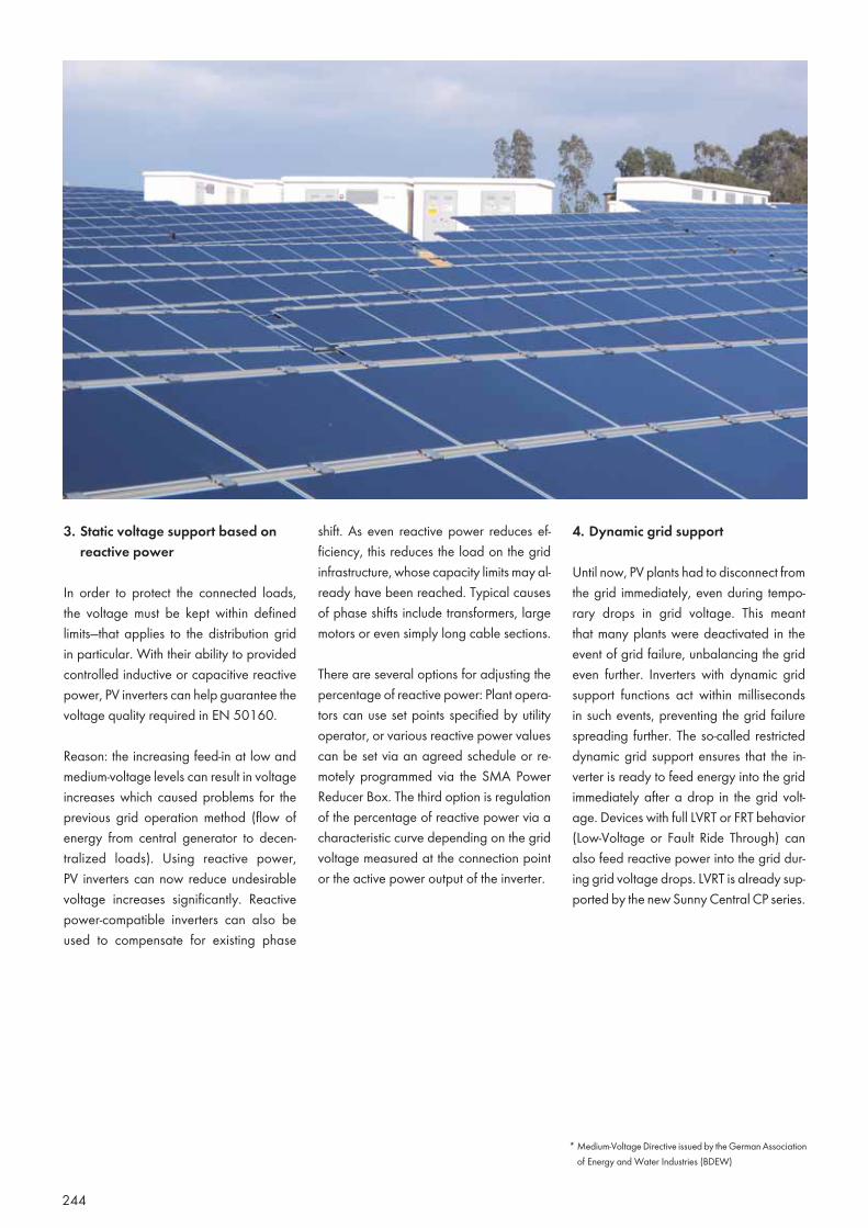
244
3. Static voltage support based on reactive power
In order to protect the connected loads, the voltage must be kept within defined limits—that applies to the distribution grid in particular. With their ability to provided controlled inductive or capacitive reactive power, PV inverters can help guarantee the voltage quality required in EN 50160.
Reason: the increasing feed-in at low and medium-voltage levels can result in voltage increases which caused problems for the previous grid operation method (flow of energy from central generator to decen-tralized loads). Using reactive power, PV inverters can now reduce undesirable voltage increases significantly. Reactive power-compatible inverters can also be used to compensate for existing phase
shift. As even reactive power reduces ef-ficiency, this reduces the load on the grid infrastructure, whose capacity limits may al-ready have been reached. Typical causes of phase shifts include transformers, large motors or even simply long cable sections.
There are several options for adjusting the percentage of reactive power: Plant opera-tors can use set points specified by utility operator, or various reactive power values can be set via an agreed schedule or re-motely programmed via the SMA Power Reducer Box. The third option is regulation of the percentage of reactive power via a characteristic curve depending on the grid voltage measured at the connection point or the active power output of the inverter.
4. Dynamic grid support
Until now, PV plants had to disconnect from the grid immediately, even during tempo-rary drops in grid voltage. This meant that many plants were deactivated in the event of grid failure, unbalancing the grid even further. Inverters with dynamic grid support functions act within milliseconds in such events, preventing the grid failure spreading further. The so-called restricted dynamic grid support ensures that the in-verter is ready to feed energy into the grid immediately after a drop in the grid volt-age. Devices with full LVRT or FRT behavior (Low-Voltage or Fault Ride Through) can also feed reactive power into the grid dur-ing grid voltage drops. LVRT is already sup-ported by the new Sunny Central CP series.
* Medium-Voltage Directive issued by the German Association of Energy and Water Industries (BDEW)
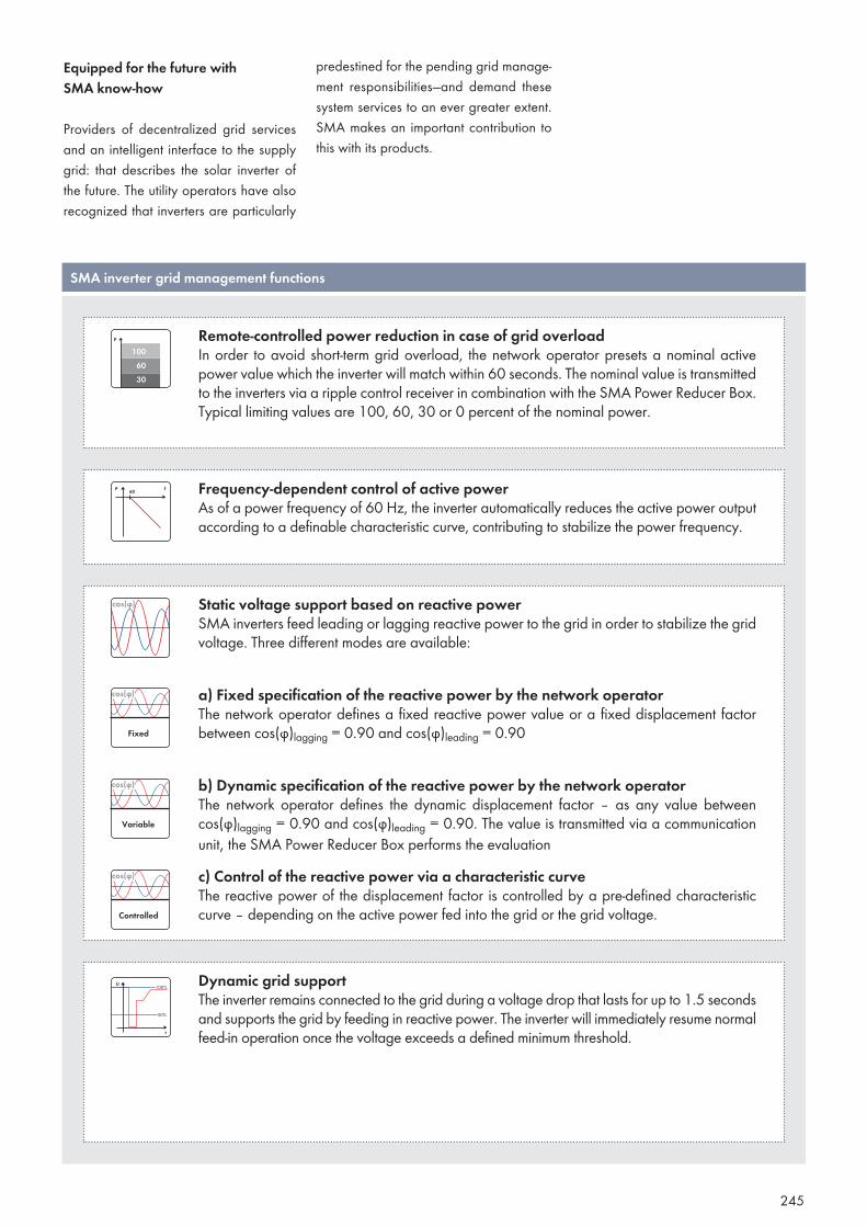
245
Equipped for the future with SMA know-how
Providers of decentralized grid services and an intelligent interface to the supply grid: that describes the solar inverter of the future. The utility operators have also recognized that inverters are particularly
predestined for the pending grid manage-ment responsibilities—and demand these system services to an ever greater extent. SMA makes an important contribution to this with its products.
SMA inverter grid management functions
Remote-controlled power reduction in case of grid overloadIn order to avoid short-term grid overload, the network operator presets a nominal active power value which the inverter will match within 60 seconds. The nominal value is transmitted to the inverters via a ripple control receiver in combination with the SMA Power Reducer Box. Typical limiting values are 100, 60, 30 or 0 percent of the nominal power.
Frequency-dependent control of active powerAs of a power frequency of 60 Hz, the inverter automatically reduces the active power output according to a definable characteristic curve, contributing to stabilize the power frequency.
Static voltage support based on reactive powerSMA inverters feed leading or lagging reactive power to the grid in order to stabilize the grid voltage. Three different modes are available:
a) Fixed specification of the reactive power by the network operatorThe network operator defines a fixed reactive power value or a fixed displacement factor between cos(ϕ)lagging = 0.90 and cos(ϕ)leading = 0.90
b) Dynamic specification of the reactive power by the network operatorThe network operator defines the dynamic displacement factor – as any value between cos(ϕ)lagging = 0.90 and cos(ϕ)leading = 0.90. The value is transmitted via a communication unit, the SMA Power Reducer Box performs the evaluationc) Control of the reactive power via a characteristic curveThe reactive power of the displacement factor is controlled by a pre-defined characteristic curve – depending on the active power fed into the grid or the grid voltage.
Dynamic grid supportThe inverter remains connected to the grid during a voltage drop that lasts for up to 1.5 seconds and supports the grid by feeding in reactive power. The inverter will immediately resume normal feed-in operation once the voltage exceeds a defined minimum threshold.
246
Besides conventional PV modules, new cell technologies and other advancements have been appearing on the market for quite some time. Of these, some can only be operated under certain conditions. For this reason, the manufacturer’s application instructions must be observed when using PV modules.
The versatile range of different topologies allows a flexible application of SMA’s inverters—combined with the suitable grounding set—providing the ideal device for any module technology. Moreover, SMA is in close contact with the module manufacturers, which means that current installation recommendations can be ef-fortlessly observed.
When selecting an inverter that meets the special PV module requirements, the generator potential in operation of vari-ous inverter topologies must be taken into account. The adjacent diagram shows a chronological map of potential courses of the generator connections during operation using several different inverters.
To help you select the right inverter for each module type, we have compiled the most important current recommendations for you. They are covered in the technical in-formation package “Module Technology” and are explained in detail there.
The right PV inverterfor every module technology
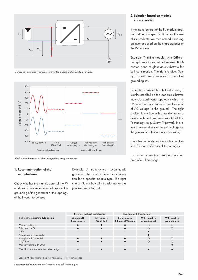
247
Block circuit diagram: PV plant with positive array grounding
Generation potential in different inverter topologies and grounding variations
1. Recommendation of the manufacturer
Check whether the manufacturer of the PV modules issues recommendations on the grounding of the generator or the topology of the inverter to be used.
Example: A manufacturer recommends grounding the positive generator connec-tion for a specific module type. The right choice: Sunny Boy with transformer and a positive grounding set.
Inverters without transformer Inverters with transformerCell technologies/module design SB xxxxxTL
SMC xxxxTLSTP xxxxTL(Quiet-Rail)
Series device SB xxx, SMC xxxx
With negative grounding set
With positive grounding set
Monocrystalline Si ● ● ● ❍ ❍Polycrystalline Si ● ● ● ❍ ❍CdTe — — — ● —Amorphous Si (superstrate) — — — ● —Amorphous Si (substrate) ● ● ● ❍ ❍CIS/CIGS ● ● ● ❍ ❍Monocrystalline Si (A-300) — — — — ●Metal foil as substrate or in module design — ● ● ● ●
Legend: ● Recommended, ❍ Not necessary, — Not recommended
Recommended combinations of inverters and cell technologies
2. Selection based on module characteristics
If the manufacturer of the PV module does not define any specifications for the use of its products, we recommend choosing an inverter based on the characteristics of the PV module.
Example: Thin-film modules with CdTe or amorphous silicone cells often use a TCO-coated pane of glass as a substrate for cell construction. The right choice: Sun-ny Boy with transformer and a negative grounding set.
Example: In case of flexible thin-film cells, a stainless steel foil is often used as a substrate mount. Use an inverter topology in which the PV generator only features a small amount of AC voltage to the ground. The right choice: Sunny Boy with a transformer or a device with no transformer with Quiet Rail Technology (e.g. Sunny Tripower). It pre-vents reverse effects of the grid voltage on the generator potential via special wiring.
The table below shows favorable combina-tions for many different cell technologies.
For further information, see the download area of our homepage.
248
The feed-in tariff requirements for photovol-taics vary widely throughout the world and are subject to frequent changes. In general, however, the following applies: For photo-voltaic power generation to be affordable at any given location, the generation costs must be sufficiently low. In most cases, con-tinuous cost reduction is necessary in order to absorb the periodic reduction in feed-in tariffs. However, only considering the indi-vidual costs of the PV plant or inverter is not enough. What is needed is a holistic view of system costs.
The term “Total Costs of Ownership,” or TCO, refers to an accounting method that not only considers original costs, but all as-pects of a PV plant that are necessary for operation for a period of 20 years or more. Such aspects include planning and installa-tion costs, repair costs and maintenance to ensure system efficiency. SMA system tech-nology helps significantly reduce the TCO in almost all areas – from planning and installation to maintenance and operation.
System costs in the spotlight Cost reduction through a holistic view of PV plants
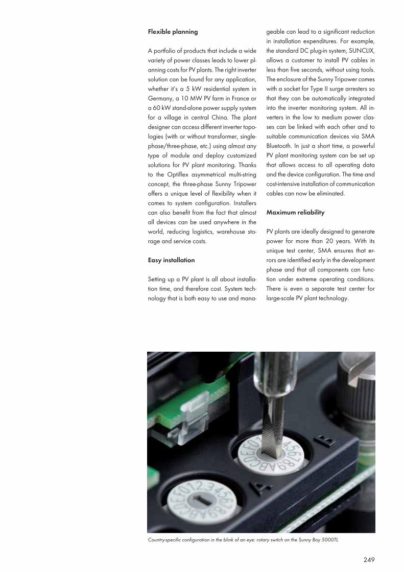
249
Flexible planning
A portfolio of products that include a wide variety of power classes leads to lower pl-anning costs for PV plants. The right inverter solution can be found for any application, whether it’s a 5 kW residential system in Germany, a 10 MW PV farm in France or a 60 kW stand-alone power supply system for a village in central China. The plant designer can access different inverter topo-logies (with or without transformer, single-phase/three-phase, etc.) using almost any type of module and deploy customized solutions for PV plant monitoring. Thanks to the Optiflex asymmetrical multi-string concept, the three-phase Sunny Tripower offers a unique level of flexibility when it comes to system configuration. Installers can also benefit from the fact that almost all devices can be used anywhere in the world, reducing logistics, warehouse sto-rage and service costs.
Easy installation
Setting up a PV plant is all about installa-tion time, and therefore cost. System tech-nology that is both easy to use and mana-
geable can lead to a significant reduction in installation expenditures. For example, the standard DC plug-in system, SUNCLIX, allows a customer to install PV cables in less than five seconds, without using tools. The enclosure of the Sunny Tripower comes with a socket for Type II surge arresters so that they can be automatically integrated into the inverter monitoring system. All in-verters in the low to medium power clas-ses can be linked with each other and to suitable communication devices via SMA Bluetooth. In just a short time, a powerful PV plant monitoring system can be set up that allows access to all operating data and the device configuration. The time and cost-intensive installation of communication cables can now be eliminated.
Maximum reliability
PV plants are ideally designed to generate power for more than 20 years. With its unique test center, SMA ensures that er-rors are identified early in the development phase and that all components can func-tion under extreme operating conditions. There is even a separate test center for large-scale PV plant technology.
Country-specific configuration in the blink of an eye: rotary switch on the Sunny Boy 5000TL
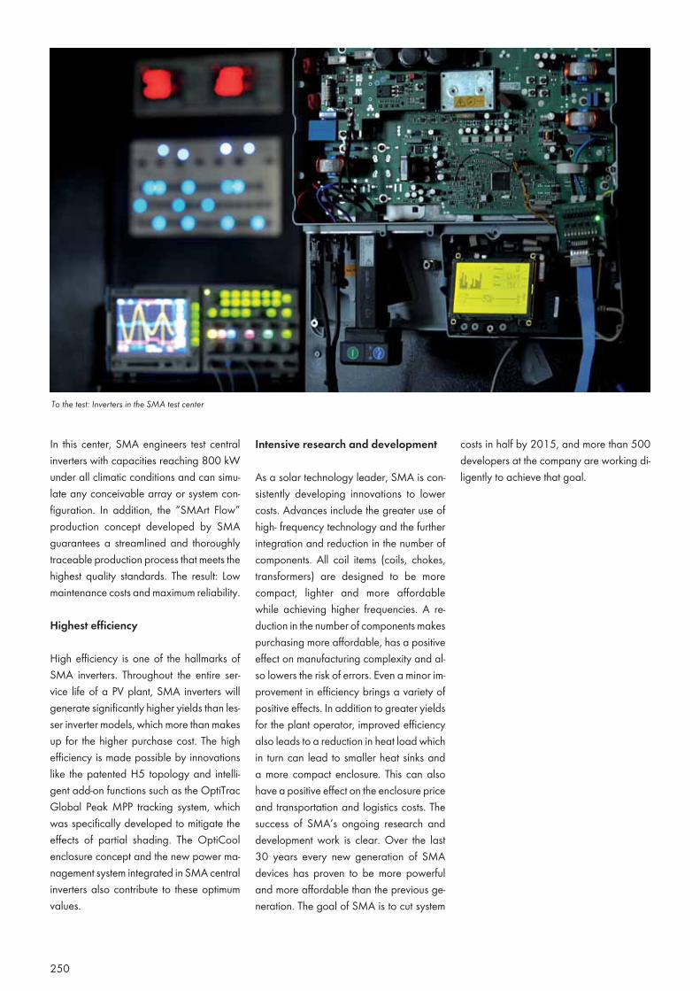
250
In this center, SMA engineers test central inverters with capacities reaching 800 kW under all climatic conditions and can simu-late any conceivable array or system con-figuration. In addition, the “SMArt Flow” production concept developed by SMA guarantees a streamlined and thoroughly traceable production process that meets the highest quality standards. The result: Low maintenance costs and maximum reliability.
Highest efficiency
High efficiency is one of the hallmarks of SMA inverters. Throughout the entire ser-vice life of a PV plant, SMA inverters will generate significantly higher yields than les-ser inverter models, which more than makes up for the higher purchase cost. The high efficiency is made possible by innovations like the patented H5 topology and intelli-gent add-on functions such as the OptiTrac Global Peak MPP tracking system, which was specifically developed to mitigate the effects of partial shading. The OptiCool enclosure concept and the new power ma-nagement system integrated in SMA central inverters also contribute to these optimum values.
Intensive research and development
As a solar technology leader, SMA is con-sistently developing innovations to lower costs. Advances include the greater use of high- frequency technology and the further integration and reduction in the number of components. All coil items (coils, chokes, transformers) are designed to be more compact, lighter and more affordable while achieving higher frequencies. A re-duction in the number of components makes purchasing more affordable, has a positive effect on manufacturing complexity and al-so lowers the risk of errors. Even a minor im-provement in efficiency brings a variety of positive effects. In addition to greater yields for the plant operator, improved efficiency also leads to a reduction in heat load which in turn can lead to smaller heat sinks and a more compact enclosure. This can also have a positive effect on the enclosure price and transportation and logistics costs. The success of SMA’s ongoing research and development work is clear. Over the last 30 years every new generation of SMA devices has proven to be more powerful and more affordable than the previous ge-neration. The goal of SMA is to cut system
costs in half by 2015, and more than 500 developers at the company are working di-ligently to achieve that goal.
To the test: Inverters in the SMA test center
251
System technology for large-scale PV plants
Launched in 2010, the Compact Power series of central inverters reduce system costs by up to 35 percent compared to their predecessors. Thanks to the weatherproof enclosure, the inverters no longer need a concrete substation, which means their total weight of around 30 tons (including transformer) is reduced by nearly 50 percent. In ambient temperatures up to 25 degrees Celsius, the devices can deliver 110 percent of rated power, increasing overall energy production. They also feature internal string failure detection, which can reliably detect a string failure out of 1,600 individual strings. Com-plex configuration is not required. In addition, the system is capable of minimizing yield loss whenever a fault occurs. Any string input affected can be remotely switched off individually so that the plant can continue feeding power into the grid at only a slightly reduced amount. The devices naturally comply with current grid management standards and include the necessary unit certificates.
System technology for off-grid power supply
AC-coupled hybrid systems are now more affordable than pure diesel-based power supply systems. They benefit from not only the low-cost AC power components, but also from the continuously declining costs for renewable power generation. Long-term savings are also achieved through the predominant use of renewable energy sources. Both the fuel costs and maintenance costs of a diesel generator are drastically reduced through the use of hybrid systems. Other cost advantages arise from the modular design of PV plants with SMA multicluster technology. Systems with 5 to 300 kW capacities can be planned with greater flexibility, expanded at any time, and easily maintained by local service technicians. Even the transport of relatively small components to remote installation sites is much more cost-effective. All things considered, PV-supported hybrid systems from SMA are not only more environmentally safe and convenient than conventional solutions, they can also boast a lower TCO.
Examples
252
The technical details of SMA inverters ben-efit in particular from the expertise of our developers and their decades of experi-ence. Many innovative SMA technologies either directly or indirectly increase the system yield immediately.
H5 Topology—patented inverter circuits for maximum efficiency
A modern inverter “consumes” between three and six percent of the energy collected by the solar modules for conversion of the direct current into alternating current, which corresponds to an efficiency of between 94 and 97 percent. SMA’s patented H5 topol-ogy, an advanced circuit for the inverter bridge, optimizes the current flow in the in-
verter and thereby reduces the loss during conversion. Basically the sinusoidal grid cur-rent is produced using the high frequency chopping and buffering of the DC current in the inverter bridge circuits. This leads to a costly oscillation of buffered energy. A spe-cial synchronization of the inverter bridges as well as the integration of a fifth semicon-ductor switch prevents this oscillation and reduces the conversion loss to less than two percent. This is how the inverters based on this technology reach new levels of perform-ance with efficiency rates above 98 percent.
Maximizing yields with High-Tech by SMA
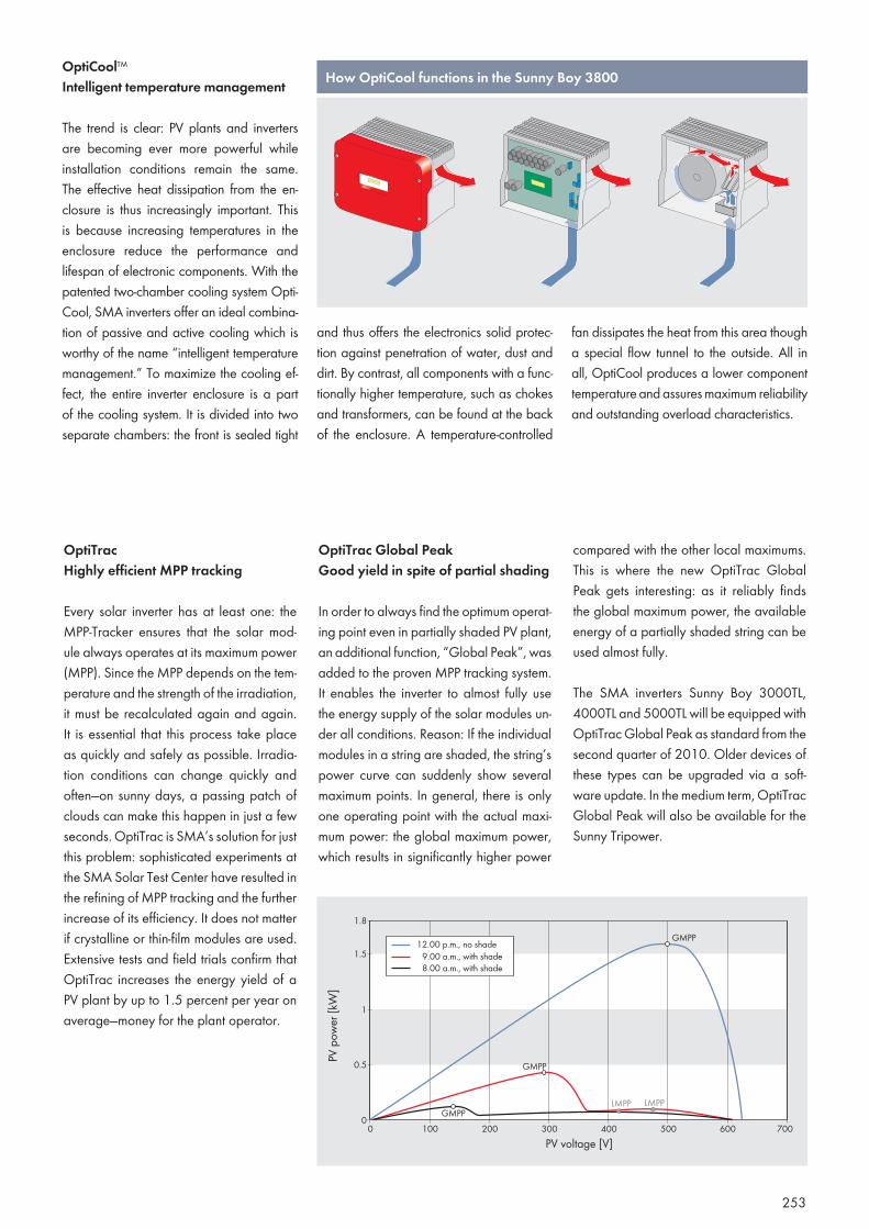
253
OptiCool™ Intelligent temperature management
The trend is clear: PV plants and inverters are becoming ever more powerful while installation conditions remain the same. The effective heat dissipation from the en-closure is thus increasingly important. This is because increasing temperatures in the enclosure reduce the performance and lifespan of electronic components. With the patented two-chamber cooling system Opti-Cool, SMA inverters offer an ideal combina-tion of passive and active cooling which is worthy of the name “intelligent temperature management.” To maximize the cooling ef-fect, the entire inverter enclosure is a part of the cooling system. It is divided into two separate chambers: the front is sealed tight
and thus offers the electronics solid protec-tion against penetration of water, dust and dirt. By contrast, all components with a func-tionally higher temperature, such as chokes and transformers, can be found at the back of the enclosure. A temperature-controlled
fan dissipates the heat from this area though a special flow tunnel to the outside. All in all, OptiCool produces a lower component temperature and assures maximum reliability and outstanding overload characteristics.
OptiTrac Highly efficient MPP tracking
Every solar inverter has at least one: the MPP-Tracker ensures that the solar mod-ule always operates at its maximum power (MPP). Since the MPP depends on the tem-perature and the strength of the irradiation, it must be recalculated again and again. It is essential that this process take place as quickly and safely as possible. Irradia-tion conditions can change quickly and often—on sunny days, a passing patch of clouds can make this happen in just a few seconds. OptiTrac is SMA’s solution for just this problem: sophisticated experiments at the SMA Solar Test Center have resulted in the refining of MPP tracking and the further increase of its efficiency. It does not matter if crystalline or thin-film modules are used. Extensive tests and field trials confirm that OptiTrac increases the energy yield of a PV plant by up to 1.5 percent per year on average—money for the plant operator.
OptiTrac Global Peak Good yield in spite of partial shading
In order to always find the optimum operat-ing point even in partially shaded PV plant, an additional function, “Global Peak”, was added to the proven MPP tracking system. It enables the inverter to almost fully use the energy supply of the solar modules un-der all conditions. Reason: If the individual modules in a string are shaded, the string’s power curve can suddenly show several maximum points. In general, there is only one operating point with the actual maxi-mum power: the global maximum power, which results in significantly higher power
compared with the other local maximums. This is where the new OptiTrac Global Peak gets interesting: as it reliably finds the global maximum power, the available energy of a partially shaded string can be used almost fully.
The SMA inverters Sunny Boy 3000TL, 4000TL and 5000TL will be equipped with OptiTrac Global Peak as standard from the second quarter of 2010. Older devices of these types can be upgraded via a soft-ware update. In the medium term, OptiTrac Global Peak will also be available for the Sunny Tripower.
How OptiCool functions in the Sunny Boy 3800
254
Safety first—this is especially important for the area of energy technology. A whole series of regulations and standards are there to protect operators, maintenance personnel, and the everyday user against accidents with electricity. SMA sets the benchmark by equipping all products with exemplary safety facilities.
SMA Grid Guard Utility interface for use worldwide
Most PV plants feed the solar energy di-rectly into the power distribution grid using an inverter. The regional utility operator is responsible for this grid: they ensure that the prescribed thresholds for voltage and frequency are complied with, that the elec-tricity grid is used effectively and is easy to maintain in the event of a fault. Of course, this only works if those feeding into the grid comply with certain rules and can be se-lectively disconnected from the grid. The automatic grid disconnection device SMA
Grid Guard prevents unintentional feeding when the supply grid is turned off (island-ing) as well as when the upper and lower limits of the standards are exceeded. In this way, it offers maximum protection for both maintenance personnel and consumer alike against excessive voltage and frequency.
Recognized safety standard
SMA was one of the first manufacturers to incorporate the requirements of the util-ity operators in the functions of their solar inverters. The maintenance-free automatic grid disconnection function has been a standard feature on the Sunny Boy invert-ers since 1995. The ongoing development of the “SMA Grid Guard” represents a rec-ognized standard for safety: in this kind of active grid monitoring, the quality of the connected grid is constantly monitored—by monitoring voltage, frequency and imped-ance. Here, fail-safe operation must be guaranteed so that periodic functional test-
A sure thingSMA protection concepts for installationand maintenance
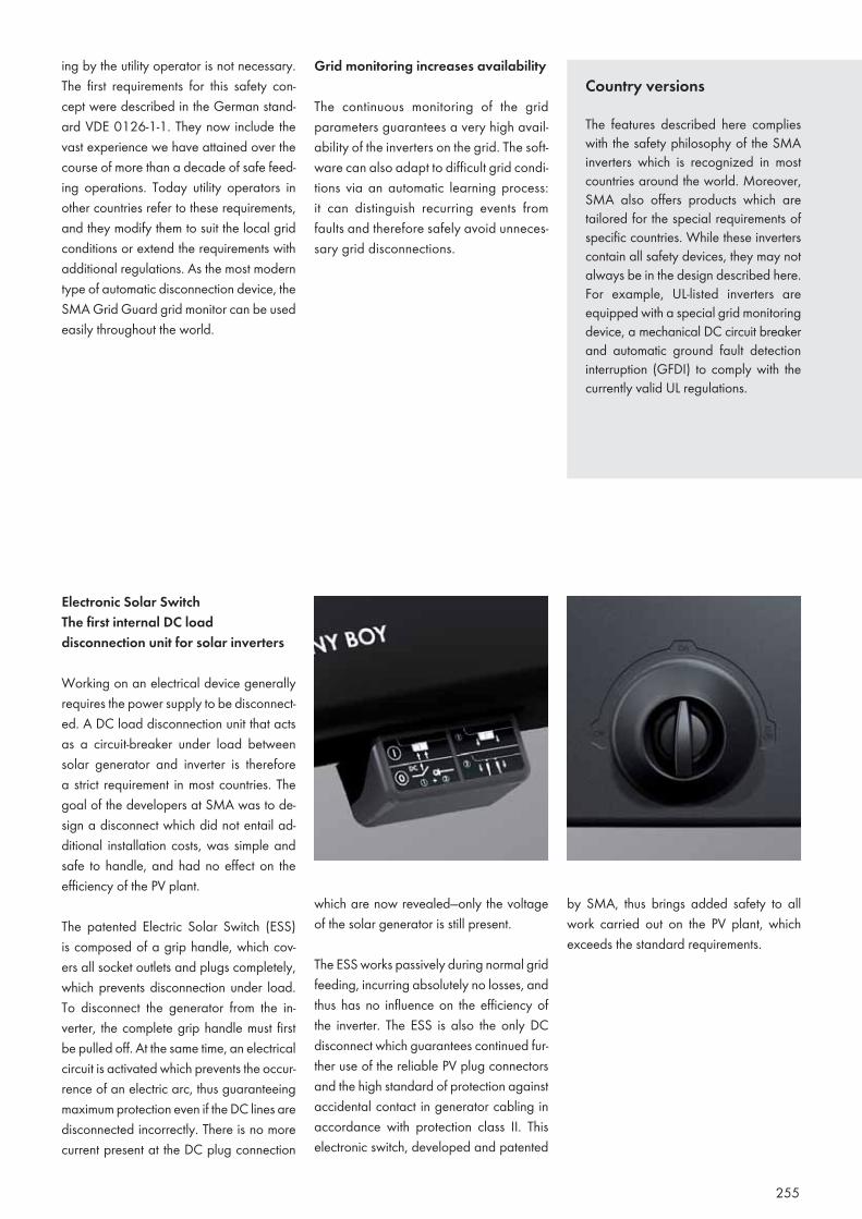
255
ing by the utility operator is not necessary. The first requirements for this safety con-cept were described in the German stand-ard VDE 0126-1-1. They now include the vast experience we have attained over the course of more than a decade of safe feed-ing operations. Today utility operators in other countries refer to these requirements, and they modify them to suit the local grid conditions or extend the requirements with additional regulations. As the most modern type of automatic disconnection device, the SMA Grid Guard grid monitor can be used easily throughout the world.
Grid monitoring increases availability
The continuous monitoring of the grid parameters guarantees a very high avail-ability of the inverters on the grid. The soft-ware can also adapt to difficult grid condi-tions via an automatic learning process: it can distinguish recurring events from faults and therefore safely avoid unneces-sary grid disconnections.
Electronic Solar Switch The first internal DC load disconnection unit for solar inverters
Working on an electrical device generally requires the power supply to be disconnect-ed. A DC load disconnection unit that acts as a circuit-breaker under load between solar generator and inverter is therefore a strict requirement in most countries. The goal of the developers at SMA was to de-sign a disconnect which did not entail ad-ditional installation costs, was simple and safe to handle, and had no effect on the efficiency of the PV plant.
The patented Electric Solar Switch (ESS) is composed of a grip handle, which cov-ers all socket outlets and plugs completely, which prevents disconnection under load. To disconnect the generator from the in-verter, the complete grip handle must first be pulled off. At the same time, an electrical circuit is activated which prevents the occur-rence of an electric arc, thus guaranteeing maximum protection even if the DC lines are disconnected incorrectly. There is no more current present at the DC plug connection
which are now revealed—only the voltage of the solar generator is still present.
The ESS works passively during normal grid feeding, incurring absolutely no losses, and thus has no influence on the efficiency of the inverter. The ESS is also the only DC disconnect which guarantees continued fur-ther use of the reliable PV plug connectors and the high standard of protection against accidental contact in generator cabling in accordance with protection class II. This electronic switch, developed and patented
by SMA, thus brings added safety to all work carried out on the PV plant, which exceeds the standard requirements.
Country versions
The features described here complies with the safety philosophy of the SMA inverters which is recognized in most countries around the world. Moreover, SMA also offers products which are tailored for the special requirements of specific countries. While these inverters contain all safety devices, they may not always be in the design described here. For example, UL-listed inverters are equipped with a special grid monitoring device, a mechanical DC circuit breaker and automatic ground fault detection interruption (GFDI) to comply with the currently valid UL regulations.
256
AC-based off-grid systems open up new possibilities for providing a stable and powerful energy supply--independent of the power distribution grid. This kind of stand-alone network not only provides the customary supply quality usually associ-ated with power distribution grids but due to its modular design, it is also very simple to install and can be easily expanded. Through the integration of more renewable energy sources, which avoid fuel costs and
are steadily becoming more economically viable, such systems are already more cost-effective than conventional systems running on diesel generators. This section explains the basic technical principles of off-grid power supply systems and demonstrates their structure and function using the exam-ple of a large hybrid system with around 270 kW generating capacity.
SMA Multicluster technologyThe path to your own power distribution grid
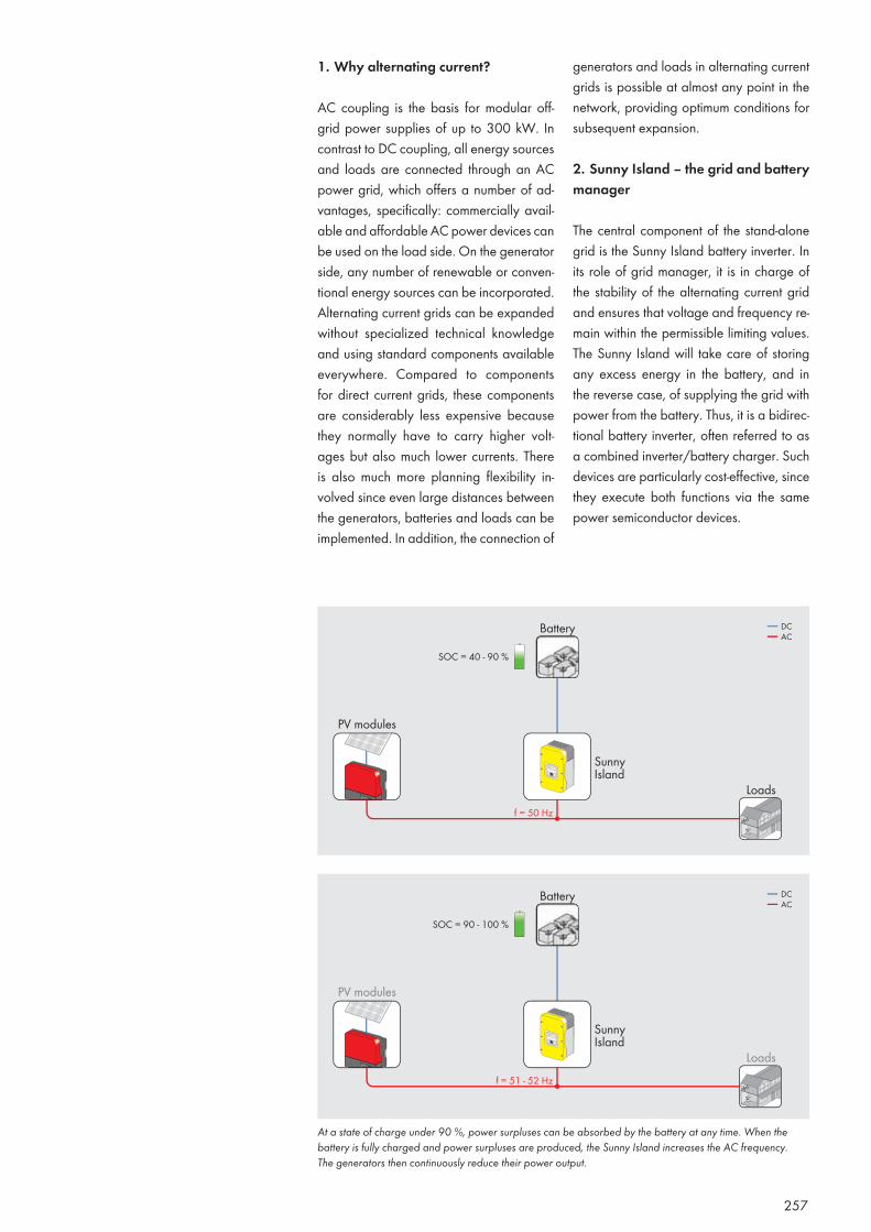
257
At a state of charge under 90 %, power surpluses can be absorbed by the battery at any time. When the battery is fully charged and power surpluses are produced, the Sunny Island increases the AC frequency. The generators then continuously reduce their power output.
1. Why alternating current?
AC coupling is the basis for modular off-grid power supplies of up to 300 kW. In contrast to DC coupling, all energy sources and loads are connected through an AC power grid, which offers a number of ad-vantages, specifically: commercially avail-able and affordable AC power devices can be used on the load side. On the generator side, any number of renewable or conven-tional energy sources can be incorporated. Alternating current grids can be expanded without specialized technical knowledge and using standard components available everywhere. Compared to components for direct current grids, these components are considerably less expensive because they normally have to carry higher volt-ages but also much lower currents. There is also much more planning flexibility in-volved since even large distances between the generators, batteries and loads can be implemented. In addition, the connection of
generators and loads in alternating current grids is possible at almost any point in the network, providing optimum conditions for subsequent expansion.
2. Sunny Island – the grid and battery manager
The central component of the stand-alone grid is the Sunny Island battery inverter. In its role of grid manager, it is in charge of the stability of the alternating current grid and ensures that voltage and frequency re-main within the permissible limiting values. The Sunny Island will take care of storing any excess energy in the battery, and in the reverse case, of supplying the grid with power from the battery. Thus, it is a bidirec-tional battery inverter, often referred to as a combined inverter/battery charger. Such devices are particularly cost-effective, since they execute both functions via the same power semiconductor devices.
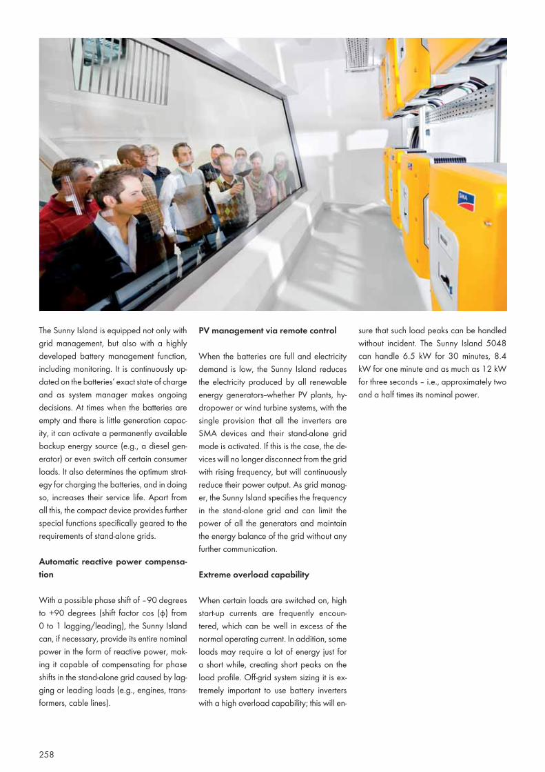
258
PV management via remote control
When the batteries are full and electricity demand is low, the Sunny Island reduces the electricity produced by all renewable energy generators--whether PV plants, hy-dropower or wind turbine systems, with the single provision that all the inverters are SMA devices and their stand-alone grid mode is activated. If this is the case, the de-vices will no longer disconnect from the grid with rising frequency, but will continuously reduce their power output. As grid manag-er, the Sunny Island specifies the frequency in the stand-alone grid and can limit the power of all the generators and maintain the energy balance of the grid without any further communication.
Extreme overload capability
When certain loads are switched on, high start-up currents are frequently encoun-tered, which can be well in excess of the normal operating current. In addition, some loads may require a lot of energy just for a short while, creating short peaks on the load profile. Off-grid system sizing it is ex-tremely important to use battery inverters with a high overload capability; this will en-
sure that such load peaks can be handled without incident. The Sunny Island 5048 can handle 6.5 kW for 30 minutes, 8.4 kW for one minute and as much as 12 kW for three seconds – i.e., approximately two and a half times its nominal power.
The Sunny Island is equipped not only with grid management, but also with a highly developed battery management function, including monitoring. It is continuously up-dated on the batteries’ exact state of charge and as system manager makes ongoing decisions. At times when the batteries are empty and there is little generation capac-ity, it can activate a permanently available backup energy source (e.g., a diesel gen-erator) or even switch off certain consumer loads. It also determines the optimum strat-egy for charging the batteries, and in doing so, increases their service life. Apart from all this, the compact device provides further special functions specifically geared to the requirements of stand-alone grids.
Automatic reactive power compensa-tion
With a possible phase shift of –90 degrees to +90 degrees (shift factor cos (φ) from 0 to 1 lagging/leading), the Sunny Island can, if necessary, provide its entire nominal power in the form of reactive power, mak-ing it capable of compensating for phase shifts in the stand-alone grid caused by lag-ging or leading loads (e.g., engines, trans-formers, cable lines).
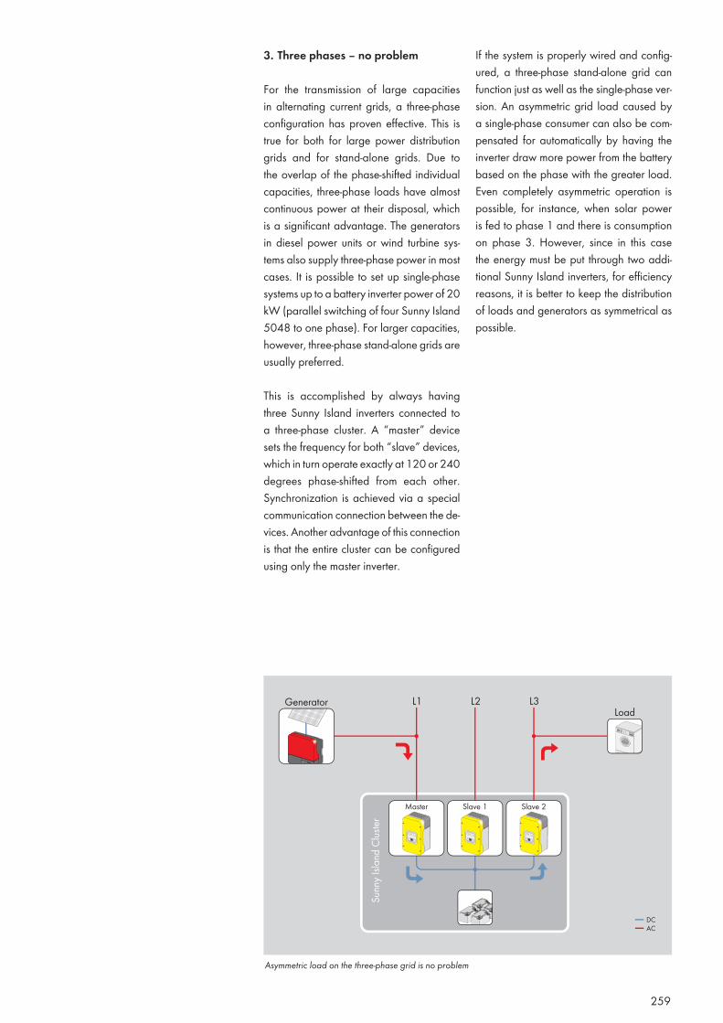
259
3. Three phases – no problem
For the transmission of large capacities in alternating current grids, a three-phase configuration has proven effective. This is true for both for large power distribution grids and for stand-alone grids. Due to the overlap of the phase-shifted individual capacities, three-phase loads have almost continuous power at their disposal, which is a significant advantage. The generators in diesel power units or wind turbine sys-tems also supply three-phase power in most cases. It is possible to set up single-phase systems up to a battery inverter power of 20 kW (parallel switching of four Sunny Island 5048 to one phase). For larger capacities, however, three-phase stand-alone grids are usually preferred.
This is accomplished by always having three Sunny Island inverters connected to a three-phase cluster. A “master” device sets the frequency for both “slave” devices, which in turn operate exactly at 120 or 240 degrees phase-shifted from each other. Synchronization is achieved via a special communication connection between the de-vices. Another advantage of this connection is that the entire cluster can be configured using only the master inverter.
If the system is properly wired and config-ured, a three-phase stand-alone grid can function just as well as the single-phase ver-sion. An asymmetric grid load caused by a single-phase consumer can also be com-pensated for automatically by having the inverter draw more power from the battery based on the phase with the greater load. Even completely asymmetric operation is possible, for instance, when solar power is fed to phase 1 and there is consumption on phase 3. However, since in this case the energy must be put through two addi-tional Sunny Island inverters, for efficiency reasons, it is better to keep the distribution of loads and generators as symmetrical as possible.
Asymmetric load on the three-phase grid is no problem
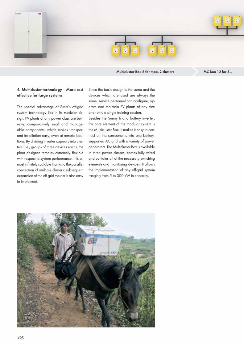
260
Since the basic design is the same and the devices which are used are always the same, service personnel can configure, op-erate and maintain PV plants of any size after only a single training session. Besides the Sunny Island battery inverter, the core element of the modular system is the Multicluster Box. It makes it easy to con-nect all the components into one battery-supported AC grid with a variety of power generators. The Multicluster Box is available in three power classes, comes fully wired and contains all of the necessary switching elements and monitoring devices. It allows the implementation of any off-grid system ranging from 5 to 300 kW in capacity.
4. Multicluster technology – More cost effective for large systems
The special advantage of SMA’s off-grid system technology lies in its modular de-sign. PV plants of any power class are built using comparatively small and manage-able components, which makes transport and installation easy, even at remote loca-tions. By dividing inverter capacity into clus-ters (i.e., groups of three devices each), the plant designer remains extremely flexible with respect to system performance. It is al-most infinitely scalable thanks to the parallel connection of multiple clusters; subsequent expansion of the off-grid system is also easy to implement.
Multicluster Box 6 for max. 2 clusters MC-Box 12 for 3...
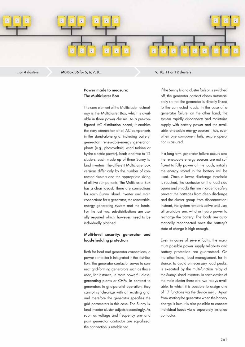
261
Power made to measure: The Multicluster Box
The core element of the Multicluster technol-ogy is the Multicluster Box, which is avail-able in three power classes. As a pre-con-figured AC distribution board, it enables the easy connection of all AC components in the stand-alone grid, including battery, generator, renewable-energy generation plants (e.g., photovoltaic, wind turbine or hydro-electric power), loads and two to 12 clusters, each made up of three Sunny Is-land inverters. The different Multicluster Box versions differ only by the number of con-nected clusters and the appropriate sizing of all live components. The Multicluster Box has a clear layout. There are connections for each Sunny Island inverter and main connections for a generator, the renewable-energy generating system and the loads. For the last two, sub-distributions are usu-ally required which, however, need to be individually planned.
Multi-level security: generator and load-shedding protection
Both for load and generator connections, a power contactor is integrated in the distribu-tion. The generator contactor serves to con-nect grid-forming generators such as those used, for instance, in more powerful diesel generating plants or CHPs. In contrast to generators in grid-parallel operation, they cannot synchronize with an existing grid, and therefore the generator specifies the grid parameters in this case. The Sunny Is-land inverter cluster adjusts accordingly. As soon as voltage and frequency pre- and post- generator contactor are equalized, the connection is established.
If the Sunny Island cluster fails or is switched off, the generator contact closes automati-cally so that the generator is directly linked to the connected loads. In the case of a generator failure, on the other hand, the system rapidly disconnects and maintains supply with battery power and the avail-able renewable energy sources. Thus, even when one component fails, secure opera-tion is assured.
If a long-term generator failure occurs and the renewable energy sources are not suf-ficient to fully power all the loads, initially the energy stored in the battery will be used. Once a lower discharge threshold is reached, the contactor on the load side opens and unlocks the line in order to safely prevent the batteries from deep discharge and the cluster group from disconnection. Instead, the system remains active and uses all available sun, wind or hydro power to recharge the battery. The loads are auto-matically reconnected once the battery’s state of charge is high enough.
Even in cases of severe faults, the maxi-mum possible power supply reliability and battery protection are guaranteed. On the other hand, load management, for in-stance, to avoid unnecessary load peaks, is executed by the multi-function relay of the Sunny Island inverters. In each device of the main cluster there are two relays avail-able, to which it is possible to assign one of 17 functions via the device menu. Apart from starting the generator when the battery charge is low, it is also possible to connect individual loads via a separately installed contactor.
...or 4 clusters MC-Box 36 for 5, 6, 7, 8... 9, 10, 11 or 12 clusters
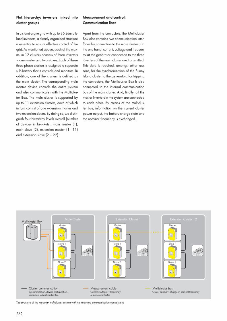
262
Flat hierarchy: inverters linked into cluster groups
In a stand-alone grid with up to 36 Sunny Is-land inverters, a clearly organized structure is essential to ensure effective control of the grid. As mentioned above, each of the max-imum 12 clusters consists of three inverters – one master and two slaves. Each of these three-phase clusters is assigned a separate sub-battery that it controls and monitors. In addition, one of the clusters is defined as the main cluster. The corresponding main master device controls the entire system and also communicates with the Multiclus-ter Box. The main cluster is supported by up to 11 extension clusters, each of which in turn consist of one extension master and two extension slaves. By doing so, we distin-guish four hierarchy levels overall (number of devices in brackets): main master (1), main slave (2), extension master (1 – 11) and extension slave (2 – 22).
Measurement and control: Communication lines
Apart from the contactors, the Multicluster Box also contains two communication inter-faces for connection to the main cluster. On the one hand, current, voltage and frequen-cy at the generator connection to the three inverters of the main cluster are transmitted. This data is required, amongst other rea-sons, for the synchronization of the Sunny Island cluster to the generator. For tripping the contactors, the Multicluster Box is also connected to the internal communication bus of the main cluster. And, finally, all the master inverters in the system are connected to each other. By means of the multiclus-ter bus, information on the current cluster power output, the battery charge state and the nominal frequency is exchanged.
The structure of the modular multicluster system with the required communication connections
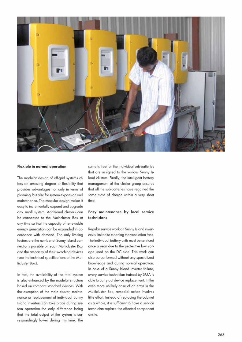
263
Flexible in normal operation
The modular design of off-grid systems of-fers an amazing degree of flexibility that provides advantages not only in terms of planning, but also for system expansion and maintenance. The modular design makes it easy to incrementally expand and upgrade any small system. Additional clusters can be connected to the Multicluster Box at any time so that the capacity of renewable energy generation can be expanded in ac-cordance with demand. The only limiting factors are the number of Sunny Island con-nections possible on each Multicluster Box and the ampacity of their switching devices (see the technical specifications of the Mul-ticluster Box).
In fact, the availability of the total system is also enhanced by the modular structure based on compact standard devices. With the exception of the main cluster, mainte-nance or replacement of individual Sunny Island inverters can take place during sys-tem operation--the only difference being that the total output of the system is cor-respondingly lower during this time. The
same is true for the individual sub-batteries that are assigned to the various Sunny Is-land clusters. Finally, the intelligent battery management of the cluster group ensures that all the sub-batteries have regained the same state of charge within a very short time.
Easy maintenance by local service technicians
Regular service work on Sunny Island invert-ers is limited to cleaning the ventilation fans. The individual battery units must be serviced once a year due to the protective low volt-age used on the DC side. This work can also be performed without any specialized knowledge and during normal operation. In case of a Sunny Island inverter failure, every service technician trained by SMA is able to carry out device replacement. In the even more unlikely case of an error in the Multicluster Box, remedial action involves little effort. Instead of replacing the cabinet as a whole, it is sufficient to have a service technician replace the affected component onsite.
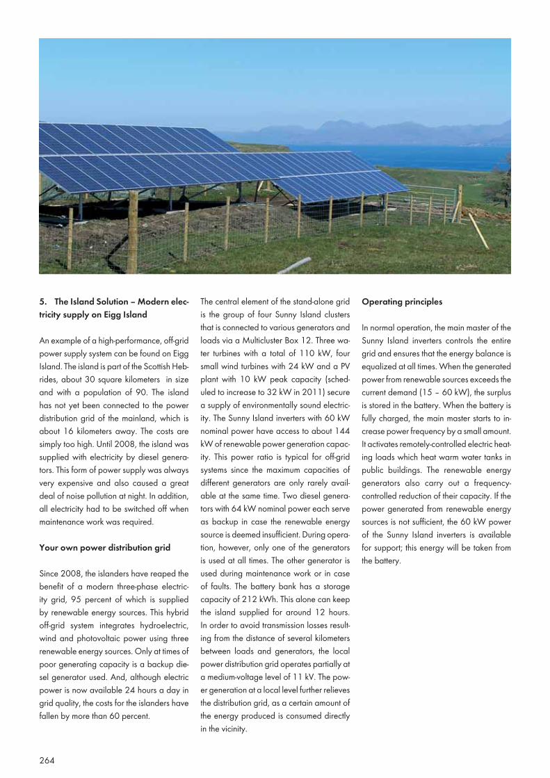
264
5. The Island Solution – Modern elec-tricity supply on Eigg Island
An example of a high-performance, off-grid power supply system can be found on Eigg Island. The island is part of the Scottish Heb-rides, about 30 square kilometers in size and with a population of 90. The island has not yet been connected to the power distribution grid of the mainland, which is about 16 kilometers away. The costs are simply too high. Until 2008, the island was supplied with electricity by diesel genera-tors. This form of power supply was always very expensive and also caused a great deal of noise pollution at night. In addition, all electricity had to be switched off when maintenance work was required.
Your own power distribution grid
Since 2008, the islanders have reaped the benefit of a modern three-phase electric-ity grid, 95 percent of which is supplied by renewable energy sources. This hybrid off-grid system integrates hydroelectric, wind and photovoltaic power using three renewable energy sources. Only at times of poor generating capacity is a backup die-sel generator used. And, although electric power is now available 24 hours a day in grid quality, the costs for the islanders have fallen by more than 60 percent.
The central element of the stand-alone grid is the group of four Sunny Island clusters that is connected to various generators and loads via a Multicluster Box 12. Three wa-ter turbines with a total of 110 kW, four small wind turbines with 24 kW and a PV plant with 10 kW peak capacity (sched-uled to increase to 32 kW in 2011) secure a supply of environmentally sound electric-ity. The Sunny Island inverters with 60 kW nominal power have access to about 144 kW of renewable power generation capac-ity. This power ratio is typical for off-grid systems since the maximum capacities of different generators are only rarely avail-able at the same time. Two diesel genera-tors with 64 kW nominal power each serve as backup in case the renewable energy source is deemed insufficient. During opera-tion, however, only one of the generators is used at all times. The other generator is used during maintenance work or in case of faults. The battery bank has a storage capacity of 212 kWh. This alone can keep the island supplied for around 12 hours. In order to avoid transmission losses result-ing from the distance of several kilometers between loads and generators, the local power distribution grid operates partially at a medium-voltage level of 11 kV. The pow-er generation at a local level further relieves the distribution grid, as a certain amount of the energy produced is consumed directly in the vicinity.
Operating principles
In normal operation, the main master of the Sunny Island inverters controls the entire grid and ensures that the energy balance is equalized at all times. When the generated power from renewable sources exceeds the current demand (15 – 60 kW), the surplus is stored in the battery. When the battery is fully charged, the main master starts to in-crease power frequency by a small amount. It activates remotely-controlled electric heat-ing loads which heat warm water tanks in public buildings. The renewable energy generators also carry out a frequency-controlled reduction of their capacity. If the power generated from renewable energy sources is not sufficient, the 60 kW power of the Sunny Island inverters is available for support; this energy will be taken from the battery.
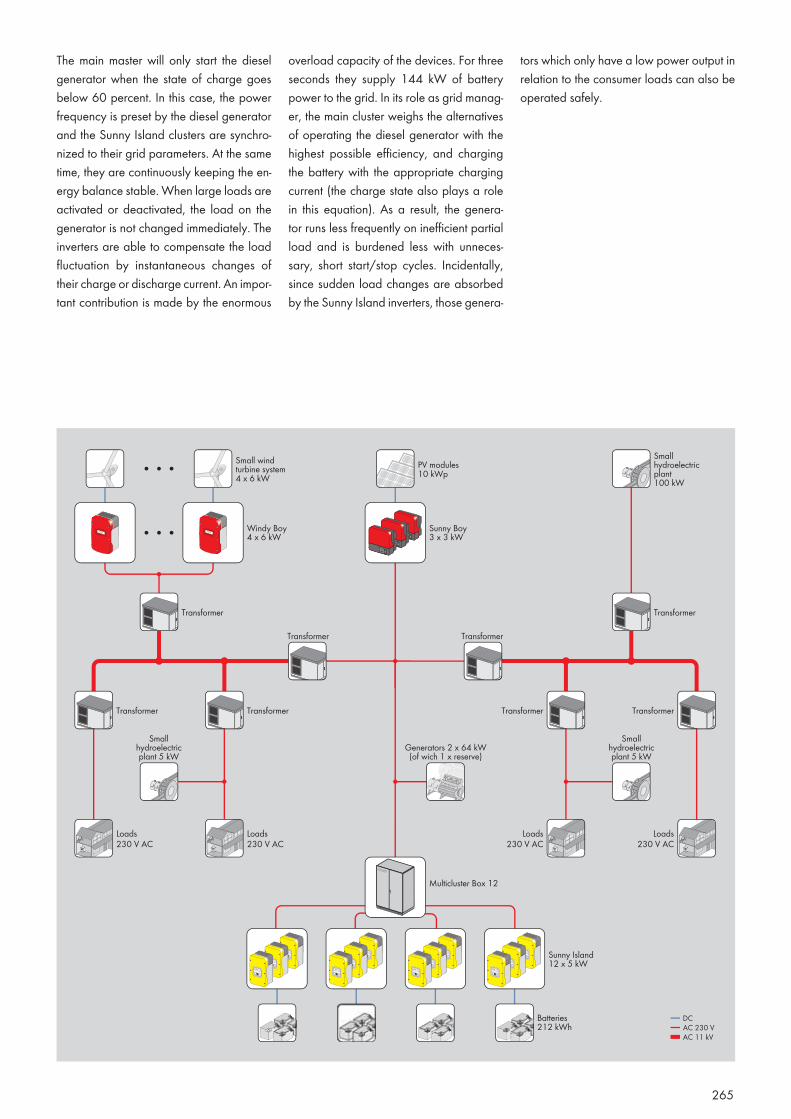
265
The main master will only start the diesel generator when the state of charge goes below 60 percent. In this case, the power frequency is preset by the diesel generator and the Sunny Island clusters are synchro-nized to their grid parameters. At the same time, they are continuously keeping the en-ergy balance stable. When large loads are activated or deactivated, the load on the generator is not changed immediately. The inverters are able to compensate the load fluctuation by instantaneous changes of their charge or discharge current. An impor-tant contribution is made by the enormous
overload capacity of the devices. For three seconds they supply 144 kW of battery power to the grid. In its role as grid manag-er, the main cluster weighs the alternatives of operating the diesel generator with the highest possible efficiency, and charging the battery with the appropriate charging current (the charge state also plays a role in this equation). As a result, the genera-tor runs less frequently on inefficient partial load and is burdened less with unneces-sary, short start/stop cycles. Incidentally, since sudden load changes are absorbed by the Sunny Island inverters, those genera-
tors which only have a low power output in relation to the consumer loads can also be operated safely.

266
REFERENCES

267
268
The future belongs to renewable energies. Fossil fuels such as oil and coal are finite resources, and damage the climate and the environment. Photovoltaic plants, on the other hand – with their low wear, good scalability and generation which matches consumption – are among the most effec-tive measures for a reliable and sustainable supply of energy, not least because the solar energy in question can cover our global consumption more than a thousand times over.
On the following pages, we show several examples demonstrating that the integra-tion of PV plants into the visual appearance of our cities and countryside is highly suc-cessful. These plants are not unsightly and often add to the aesthetic value of many buildings.
Photovoltaic plants are now used as the basis for off-grid systems in many corners of the world in order to set up energy sup-plies in remote off-grid regions, which would otherwise be unthinkable.
PV plants The appropriate inverter for every application
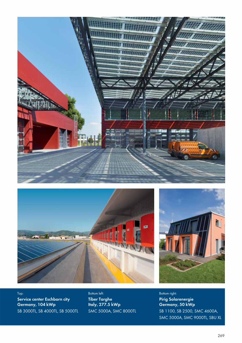
269
Top:Service center Eschborn cityGermany, 104 kWpSB 3000TL, SB 4000TL, SB 5000TL
Bottom left:Tiber Targhe Italy, 277.5 kWpSMC 5000A, SMC 8000TL
Bottom right:Pirig SolarenergieGermany, 50 kWp SB 1100, SB 2500, SMC 4600A, SMC 5000A, SMC 9000TL, SBU XL
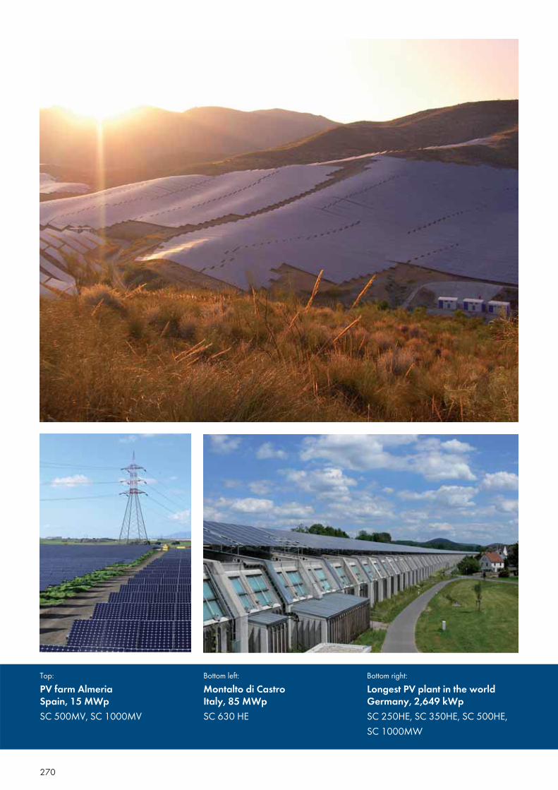
270
Top:PV farm AlmeriaSpain, 15 MWpSC 500MV, SC 1000MV
Bottom left:Montalto di CastroItaly, 85 MWpSC 630 HE
Bottom right:Longest PV plant in the worldGermany, 2,649 kWpSC 250HE, SC 350HE, SC 500HE, SC 1000MW
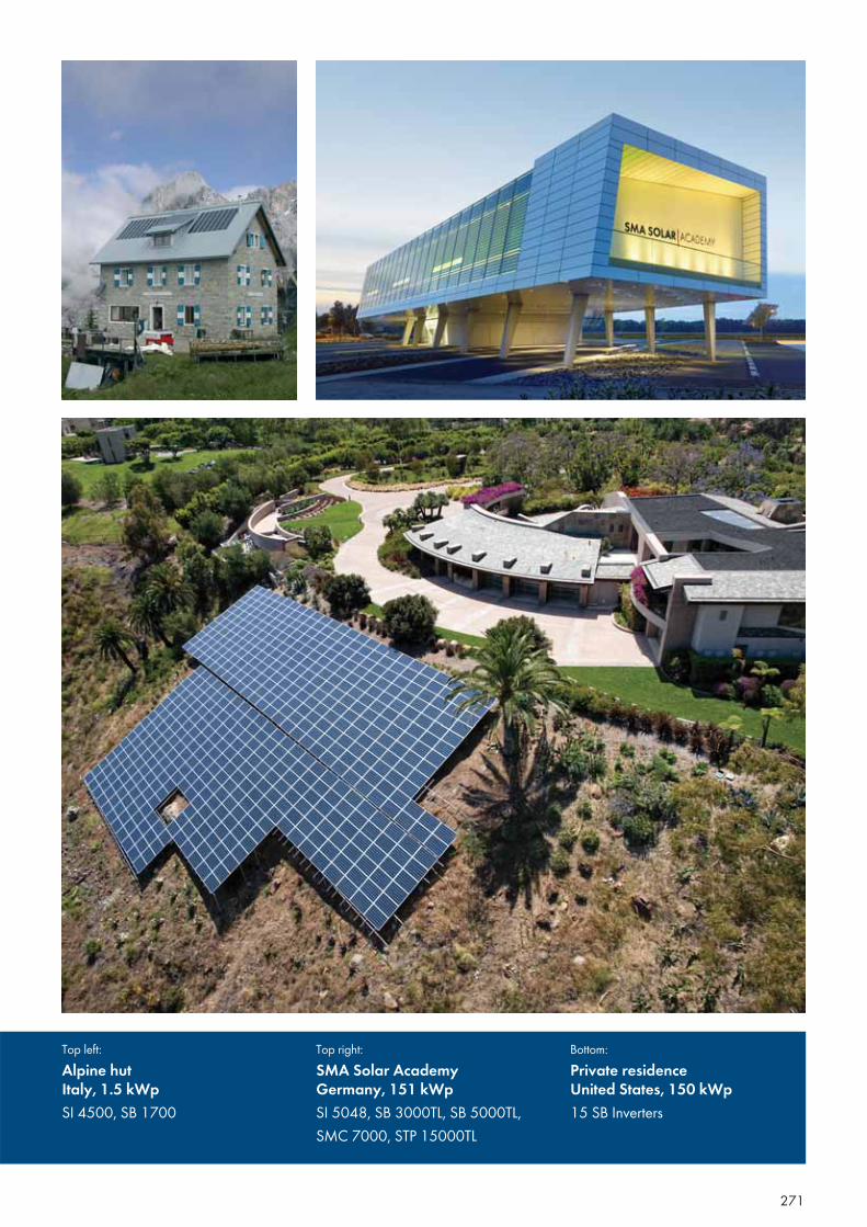
271
Top left:Alpine hutItaly, 1.5 kWpSI 4500, SB 1700
Top right:SMA Solar AcademyGermany, 151 kWpSI 5048, SB 3000TL, SB 5000TL, SMC 7000, STP 15000TL
Bottom:Private residenceUnited States, 150 kWp15 SB Inverters
272
Central InverterCentral inverters are particularly well-suit-ed for use in PV plants with a homogenous structure (modules of the same kind with identical orientation and tilt). They are used for plants starting at around 100kW and are usually designed for outdoor in-stallation.
DumploadDumpload is a load which can be sponta-neously activated in the event of an energy surplus and can also be used to balance out strong load fluctuations. Consumers with storage capability (pumps, cooling units, boilers) are the most energy sensible. However, for the actual technical function, appropriately cooled resistors suffice.
ESS (Electronic Solar Switch)The ESS is a DC disconnection unit integrat-ed into the inverter to safely disconnect a solar array from the inverter. The ESS has a grip handle for easy operation. After pulling down the grip handle, the DC plugs can be accessed and disconnected with no risk of arcing. Disconnecting the plug results in im-mediate disconnection from the live array.
H5 TopologyThe inverter bridge with H5 topology fea-tures a fifth semiconductor switch, which en-sures optimal efficiency during conversion at an efficiency rate of 98 percent.
HFHF stands for “High Frequency” and also designates the new Sunny Boy series with high frequency transformers. The compact, galvanically isolating inverters provide very high efficiency for devices with transformers.
Glossary Explanations on Solar Technology
273
Low-Voltage Ride Through (LVRT)Network management function from the field of dynamic grid support. When there is a short disruption in grid voltage, the invert-er does not switch off, as has been required until now, but supports the grid with reactive power. After the disturbance, it immediately resumes feeding. In Germany, LVRT is re-quired as of January 2011 for plants at the medium-voltage level.
Maximum Power Point (MPP)The operational point (current / voltage) of the PV array under which the highest pos-sible power under the prevailing conditions is harvested. The actual MPP changes con-stantly depending on the level of irradiation and the temperature.
MPP TrackerA device that adjusts the voltage and cur-rent of a PV array so that it operates at its “Maximum Power Point.”
MSDPart of “Mains monitoring with allocated Switching Devices”. This is a mandatory safety device which prevents power from a solar energy system from being fed into an external power grid when the public sup-ply grid is not functioning. This function is taken over by the Sunny Boy and Sunny Mini Central using SMA Grid Guard, mak-ing a regular test unnecessary due to their single fault characteristics.
Multistring InverterAn inverter which, to a great extent, com-bines the advantages of several string inverters (separate MPP tracking of indi-vidual strings) and a central inverter (low specific costs).
OptiCool™A patented enclosure concept by SMA, in which the interior of the enclosure is di-vided into two compartments. The sealed chamber protects the sensitive electronics from water, dust and debris. The second chamber contains transformers and chokes, as well as other components, and can be actively cooled when necessary.
OptiflexAn innovative and highly-flexible Sunny Tripower concept. The Sunny Tripower fea-tures an asymmetric multi-string input with two MPP trackers for custom-fit installation with a nearly unlimited numbers of modules and maximum system efficiency.
OptiprotectThe Sunny Tripower features a completely new and comprehensive safety concept. Its electronic string fuses, automatic string fail-ure detection and overvoltage protection, that can be integrated into the enclosure, all work to monitor the PV system, ensure safe operation, and optimally secure en-ergy yield.
OptiTrac Global PeakAnother advance in our time-tested OptiTrac MPP tracker for operation in partially-shaded PV plants. This specialized operation man-agement system ensures that the modules are constantly operated at the point of maximum power even when there are multiple maxi-mum power points, without causing measur-able yield loss (loss < 0.2 percent).
Power BalancerThe Power Balancer is a standard Sunny Mini Central inverter function that prevents the formation of an unbalanced load dur-ing three-phase grid feeding. This is accom-plished by connecting three inverters to a three-phase feeding unit via a control line.
Quick ModuleA removable communication and con-figuration module for the new Sunny Boy HF series. The Quick Module contains a rotary switch for country-specific configura-tion and a Bluetooth® NetID, as well as an SD card slot. The optional Quick Module RS485 also features an RS485 interface and a multifunction relay.
SMA Grid GuardAccording to predefined parameters, the SMA Grid Guard concept monitors factors such as the voltage and frequency of the connected AC grid. This serves to prevent the formation of islanding in the event of grid disconnection (see also “MSD”). Grid Guard enables simple and reliable opera-tion of SMA inverters on nearly all world-wide electrical power grids.
SMA Plug-in GroundingA grounding set for the new Sunny Boy HF series. Grounding is quick and simple—an easy plug-in without having to open the en-closure. The polarity is defined by the orien-tation in which the grounding is attached.
String InverterIn string technology, the photovoltaic array is divided into separate module surfaces and each of these “strings” is assigned to a separate string inverter. This technology reduces system costs while at the same time substantially simplifying installation and in-creasing the energy yield and system avail-ability.
SUNCLIX®
A DC plug system for many SMA invert-ers, developed in cooperation with Phoenix Contact. The field plugs can be connected to almost any cable without tools, and are included with the inverters free of charge.
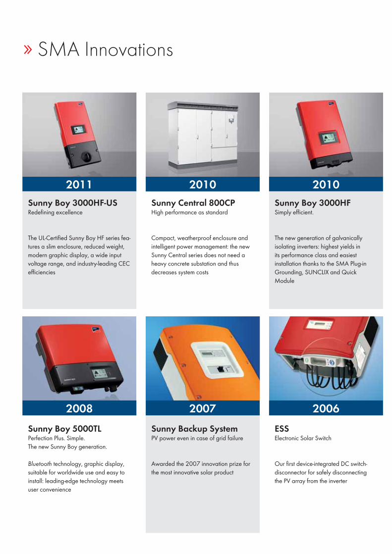
» SMA Innovations
2011
2008
2010
2007
2010
2006
Sunny Central 800CPHigh performance as standard
Compact, weatherproof enclosure and intelligent power management: the new Sunny Central series does not need a heavy concrete substation and thus decreases system costs
Sunny Boy 3000HF Simply efficient.
The new generation of galvanically isolating inverters: highest yields in its performance class and easiest installation thanks to the SMA Plug-in Grounding, SUNCLIX and Quick Module
Sunny Backup SystemPV power even in case of grid failure
Awarded the 2007 innovation prize for the most innovative solar product
ESSElectronic Solar Switch
Our first device-integrated DC switch-disconnector for safely disconnecting the PV array from the inverter
Sunny Boy 3000HF-USRedefining excellence
The UL-Certified Sunny Boy HF series fea-tures a slim enclosure, reduced weight, modern graphic display, a wide input voltage range, and industry-leading CEC efficiencies
Sunny Boy 5000TLPerfection Plus. Simple. The new Sunny Boy generation.
Bluetooth technology, graphic display, suitable for worldwide use and easy to install: leading-edge technology meets user convenience
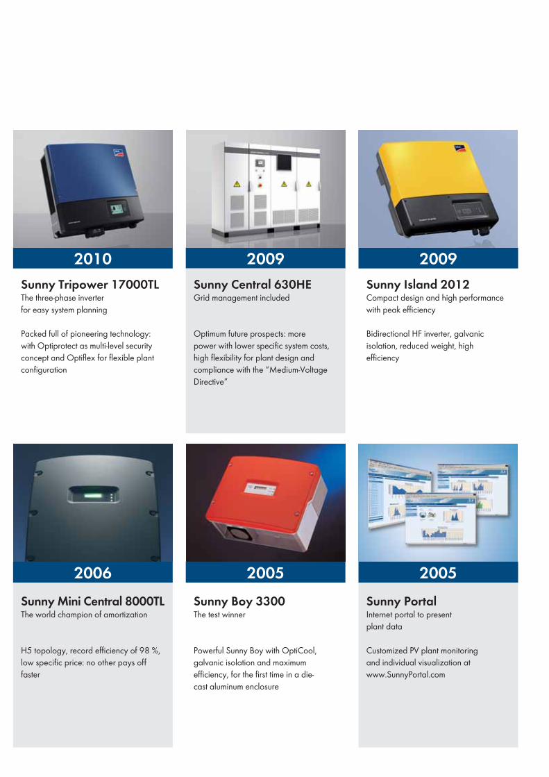
2010
2006
2009
2005
2009
2005
Sunny Tripower 17000TLThe three-phase inverter for easy system planning
Packed full of pioneering technology: with Optiprotect as multi-level security concept and Optiflex for flexible plant configuration
Sunny PortalInternet portal to present plant data
Customized PV plant monitoring and individual visualization at www.SunnyPortal.com
Sunny Boy 3300The test winner
Powerful Sunny Boy with OptiCool, galvanic isolation and maximum efficiency, for the first time in a die-cast aluminum enclosure
Sunny Island 2012Compact design and high performance with peak efficiency
Bidirectional HF inverter, galvanic isolation, reduced weight, high efficiency
Sunny Central 630HEGrid management included
Optimum future prospects: more power with lower specific system costs, high flexibility for plant design and compliance with the “Medium-Voltage Directive”
Sunny Mini Central 8000TLThe world champion of amortization
H5 topology, record efficiency of 98 %, low specific price: no other pays off faster
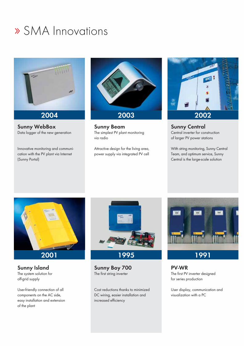
Sunny Boy 700The first string inverter
Cost reductions thanks to minimized DC wiring, easier installation and increased efficiency
2004
2001
2003
1995
2002
1991
Sunny WebBoxData logger of the new generation
Innovative monitoring and communi-cation with the PV plant via Internet (Sunny Portal)
Sunny CentralCentral inverter for construction of larger PV power stations
With string monitoring, Sunny Central Team, and optimum service, Sunny Central is the large-scale solution
Sunny BeamThe simplest PV plant monitoringvia radio
Attractive design for the living area, power supply via integrated PV cell
Sunny IslandThe system solution for off-grid supply
User-friendly connection of all components on the AC side, easy installation and extension of the plant
PV-WRThe first PV inverter designed for series production
User display, communication and visualization with a PC
» SMA Innovations
Publication Information
Published by:SMA America, LLC
PhotosStefanie AumillerAndreas BerthelStephan DaubLucidmediaConstantin MeyerJoan Carles Milà
SMA, Sunny Boy, Sunny Central, Sunny Island, Sunny Beam, Sunny Design, Sunny Explorer, Sunny Family, Hydro Boy, smartload, Sunny, Sunny Backup, Sunny Easy, Sunny PRO Club, Sunny Team, Sunny Tripower, OptiTrac, Windy Boy, Sunny Matrix, Sunny Portal, Sunny Tower, Sunny WebBox, Multi-String, OptiCool, H5, Grid Guard and Power Balancer are registered trademarks of SMA Solar Technology AG. The Bluetooth word mark and logos are registered trademarks owned by Bluetooth SIG, Inc. and any use of these marks by SMA Solar Technology AG is under license. SUNCLIX is a registered trademark of PHOENIX CONTACT GmbH & Co. KG.Text and illustrations reflect the current state of technology at the time of publication. Subject to technical changes. No liability shall be accepted for printing errors. Printed on chlorine-free paper.
All trademarks are acknowledged, even if not explicitly identified as such. A lack of identification does not mean that a product or symbol is not trademarked. This text and excerpts thereof mayonly be reprinted with written approval from the publisher.
© Copyright 2011, SMA Solar Technology AGAll rights reserved.

SFK_
KUS1
1371
0 Su
bject
to tec
hnica
l cha
nges
. No l
iabilit
y for
typog
raphic
al err
ors. P
rinted
on ch
lorine
-free p
aper.
www.SMA-America.com
SUNNY FAMILY2011/2012
SMA Solar Technology
SMA America, LLC
SUNNY FAMILY 2011/2012
SMA Solar Technology AGwww.SMA.deSMA America, LLCwww.SMA-America.comSMA Technology Australia Pty., Ltd.www.SMA-Australia.com.auSMA Benelux SPRLwww.SMA-Benelux.comSMA Beijing Commercial Co., Ltd.www.SMA-China.comSMA Canada, Inc.www.SMA-Canada.caSMA Czech Republic s.r.o.www.SMA-Czech.com
SMA France S.A.S.www.SMA-France.comSMA Solar UK Ltd.www.SMA-UK.comSMA Hellas AEwww.SMA-Hellas.comSMA Ibérica Tecnología Solar, S.L.www.SMA-Iberica.comSMA Solar India Pvt. Ltd.www.SMA-India.comSMA Italia S.r.l.www.SMA-Italia.comSMA Technology Korea Co., Ltd.www.SMA-Korea.com
Recommended


![[5] PROGRAM SEMESTER PKN SMA](https://img.dokumen.tips/doc/110x75/6333d07876a7ca221d086637/5-program-semester-pkn-sma.jpg)


