INTERNATIONAL JOURNAL OF CIVIL AND STRUCTURAL ENGINEERING
Volume 2, No 1, 2011
© Copyright 2010 All rights reserved Integrated Publishing services
Research article ISSN 0976 – 4399
Received on June 2011 published on September 2011 1
Influence of structural and soil parameters on Mat deflection Imam, Md. Hasan.
Lecturer, Department of Civil Engineering, Southern University, Bangladesh.
ABSTRACT
The present study was carried out to investigate the deflection characteristics of mat
foundation for structural and soil parameters. The gap in knowledge about mat deflection
characteristics brings some uncertainty in analysis of mat foundation and may result in its
uneconomical design or unsafe design. For economy in design of mat with service core
requires comprehensive understanding of the influence of it on mat. This work involved
an extensive investigation of structural parameters effect on deflection of mat foundation
using Finite Element Program SAFE V8. A comparative study has been made among
some critical positions of the mat foundation using finite element methods in order to
perceive the influence of different parameters that assist to understand the practical safety
limit of the design characteristics. As only rigid frame structure with gravity and lateral
load cases are considered here for the present work, further scope of the study maybe
based on other types of structural system and mathematical modeling of mat response.
Key words: Deflection, Mat, Finite Element, Structural Parameters, Soil parameter
1. Introduction
1.1 Overview
Mat foundation is a simple structure. Once everything is set by engineers and architects
for a particular project, it has a relatively small number of parameters to be dealt with,
such as elastic properties of mat materials, modulus of sub grade reaction of supporting
soil and mat thickness. But difficulty with the formulation of the characteristics of mat
arises from its loading patterns, geometric properties and supported superstructure
parameters. So the enthusiasm of present work goes to investigate the mat response
against the structure parameters such as mat thickness, column spacing, column size,
width of overhanging portion, span-width (L/B) ratio of panel and type of soil.
1.2 Objectives of the work
The objectives of this thesis work are
1. To select the effective parameters for mat foundation that affects the mat
response.
2. To study the influence of different structure parameters such as mat thickness,
column spacing and size, overhanging portion of mat and span –width ratio of
panel etc. on mat deflection.
Influence of structural and soil parameters on Mat deflection
Imam, Md. Hasan.
International Journal of Civil and Structural Engineering
Volume 2 Issue 1 2011 2
1.3 Scope of the Work
An understanding of the actual behavior of mat foundation is essential to ensure
economy and safety in design. Present study focuses on influences of structural
parameters of framed structure building and that of mat foundation. This study
recommends mat deflection characteristics. It reveals the changes in mat deflection
behavior due to variation of different parameters.
2. Modeling and Structural Idealization
2.1 Overview
Finite element method is the most powerful and versatile of all the available numerical
analysis techniques. In this method the structure to be analyzed is modeled as an
assemblage of a finite number of elements and the displacements of the
connecting points. The applied loads are transferred into equivalent nodal points
and for each element; the relationship between the nodal points and nodal
displacements is established. Through displacement method assembling of the
element load-displacement relations for the whole structure can be found upon which
nodal displacements and stress- strain at the nodes are found concurrently.
The ultimate objective of this study is to analyze mat foundation by Finite Element
Method. Mat foundation is a three dimensional thick plate structure. When superstructure
loads are being transferred, mat transverse bending moment and flexural shear are the
most important internal forces produced in response to the loads. Super structural loads
usually axial column forces and column base transferred moments. Thick plate option
has been taken into considerations readily available in most recent and pioneer mat
foundation analysis and design by Finite Element Method named SAFE. Non linear
analysis is well adjusted along with discrete elastic springs under mat foundation found
very favorable in this software. For parametric study a number of idealized fifteen storey
buildings with mat foundation has been modeled and analyzed both for vertical and
lateral loads with renowned three dimensional structural analysis software ETABS.
Three dimensional analysis model support reactions i.e. axial forces and base moments
have been transferred to finite element mat foundation analysis software SAFE.. In
present study mat with different mat thickness, column spacing, column size, width of
overhanging portion, L/B ratio of panel and type of soil have been taken into account for
sensitivity analysis and comparison considering sub grade reaction is already known
by soil test results and conventional method.
For present study of mat response a typical fifteen storey frame building is modeled as a
reference building-mat system. This reference model has four bays in both directions. In
this model column center to center spacing and column cross sectional properties were
taken uniform. For profound study other building-mat systems with different structural
and bearing soil parameters were modeled which have same number of bays. The
variations of parameters of these models are given below in Table 1.
Influence of structural and soil parameters on Mat deflection
Imam, Md. Hasan.
International Journal of Civil and Structural Engineering
Volume 2 Issue 1 2011 3
Table 1: Variations of parameters of the models
Parameters
Reference
value
Ranges of variations
Mat thickness 5ft 4ft, 4.5ft, 5ft, 5.5ft, 6ft
Column spacing 20ft 16ft, 18ft, 20ft, 22ft, 24ft
Column Size 20”x20” 16”x16”, 18”x18”, 20”x20”, 22”x22”, 24”x24”
Over hanging portion 3ft 2ft, 2.5ft, 3ft, 3.5ft, 4ft
L/B ratio of the panel 1.0 0.8, 0.9, 1.0, 1.1, 1.2
Modulus of sub grade
reaction
150 psi/in For sandy soil :
18 psi/in, 35 psi/in, 60 psi/in, 150 psi/in, 236
psi/in, 295 psi/in, 472 psi/in.
For clayey soil:
44 psi/in, 88 psi/in, 150 psi/in, 177psi/in,
250psi/in, 350 psi/in.
The material properties of mat are taken as follows –
Poison’s ratio, = 0.25
Modulus of elasticity, E = 3600 ksi
Shear modulus, G = 1500 ksi
Concrete strength, f’c = 4 ksi
and steel yield strength, fy = 60 ksi.
2.2 Idealization of Mat
Mat is a three dimensional thick plate structure that acts integrally with the building
frame and supported by soil strata. Now-a-days, parking access for high rise
building is totally dependent on underground basement. Available methods do
not emphasis different structural parameters such as modulus of sub grade reaction, mat
thickness, column spacing, column size, over hanging portion, L/B ratio of the panel and
mat foundation interactions. Variation of theses parameter can influence the behavior
of mat significantly. For present study uniform mat thickness was varied from 4.0 feet
to 6.0 feet both for square and rectangular column grids model. Later column
spacing variation from 16 feet to 24 feet and column size variation from
16’’x16”to 24”x24” were critically reviewed. Finally over hanging portion variation from
2 feet to 4 feet and the panel span-width(L/B) ratio variation from 0.8 to 1.2 were also
decisively observed.
A soil structure interaction is an important process of predicting overall structural
response of any sub grade structure. Settlement profile and soil pressures for mat
foundations are dependent on relative stiffness of mat and it’s supporting soil strata. In
present study Winkler's model on foundation on elastic medium has been used for
representation of the soil behavior by discrete vertical nonlinear springs. Soil has
been idealized by modulus of sub grade reaction (ks).
Influence of structural and soil parameters on Mat deflection
Imam, Md. Hasan.
International Journal of Civil and Structural Engineering
Volume 2 Issue 1 2011 4
Bowles (1988) suggested the following equations for approximating k value from
allowable bearing capacity.
k = 12* Factor of Safety * q, (In kip per cubic feet unit).
Where,
q= Allowable bearing capacity in ksf.
F.S = 2.5 (BNBC, 1993)
In present study modulus of sub grade reaction (k) for sandy soil was varied from 18
psi/in to 472 psi/in and for clayey soil modulus of sub grade reaction (k) was varied
from 44 psi/in to 350 psi/in and were assigned in SAFE program as an input spring
data. ACI318-95 design code was reviewed by this program and concrete's Poison
ratio was taken as 0.25.
3. Analysis of Mat deflection characteristics
3.1 Overview
Structurally mat is a two way flexural member supporting superstructures and directly
supported by soil support. Naturally, design of mat is governed by moment, shear,
punching shear and deflection considerations. In order to be structurally safe, mat must
be strong enough to resist the moments, shear and punching coming from the supported
column loads. And deflection must be within allowable limits. So for the present study
the deflection characteristic is observed.
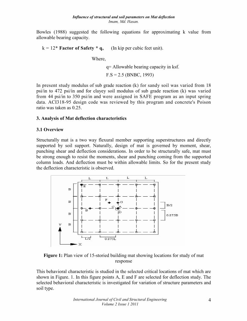
Figure 1: Plan view of 15-storied building mat showing locations for study of mat
response
This behavioral characteristic is studied in the selected critical locations of mat which are
shown in Figure. 1. In this figure points A, E and F are selected for deflection study. The
selected behavioral characteristic is investigated for variation of structure parameters and
soil type.
Influence of structural and soil parameters on Mat deflection
Imam, Md. Hasan.
International Journal of Civil and Structural Engineering
Volume 2 Issue 1 2011 5
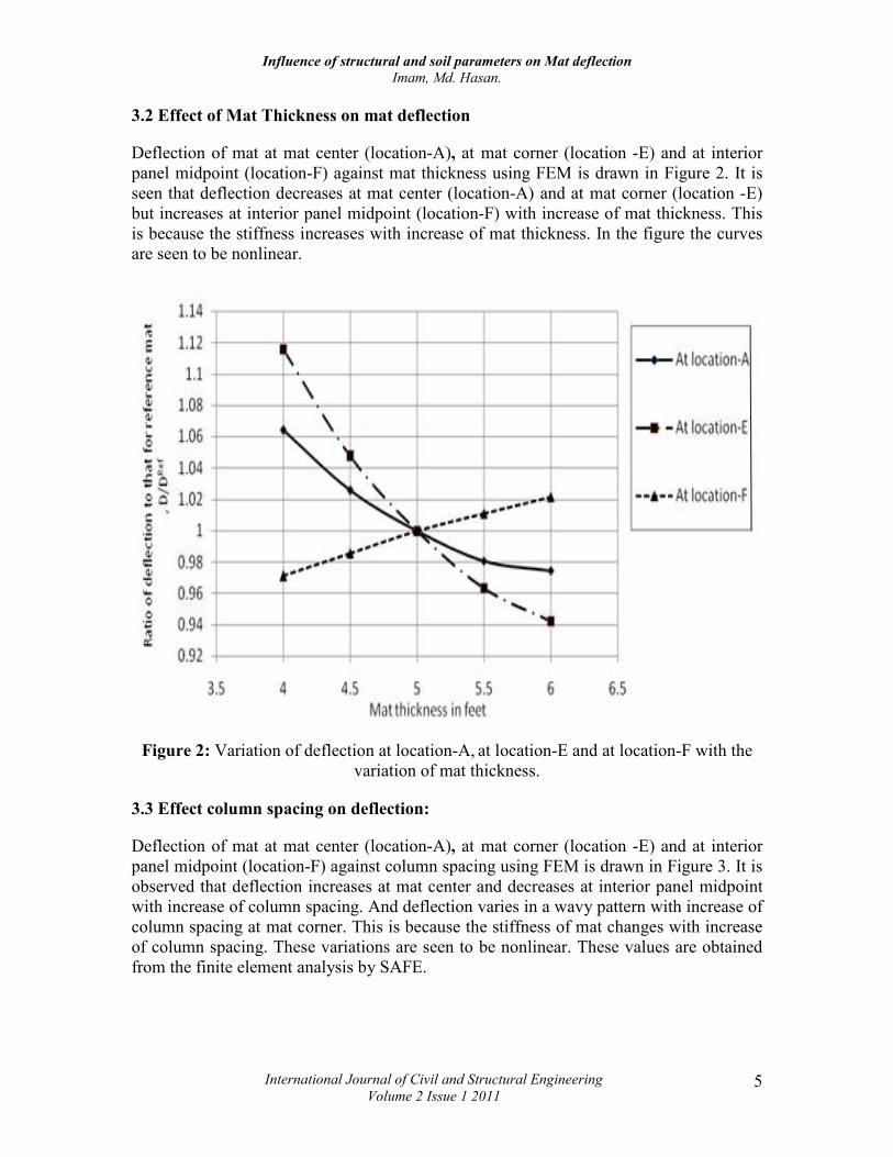
3.2 Effect of Mat Thickness on mat deflection
Deflection of mat at mat center (location-A), at mat corner (location -E) and at interior
panel midpoint (location-F) against mat thickness using FEM is drawn in Figure 2. It is
seen that deflection decreases at mat center (location-A) and at mat corner (location -E)
but increases at interior panel midpoint (location-F) with increase of mat thickness. This
is because the stiffness increases with increase of mat thickness. In the figure the curves
are seen to be nonlinear.
Figure 2: Variation of deflection at location-A, at location-E and at location-F with the
variation of mat thickness.
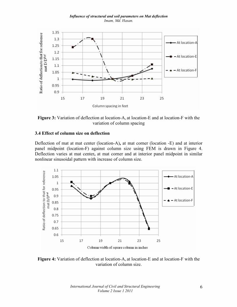
3.3 Effect column spacing on deflection:
Deflection of mat at mat center (location-A), at mat corner (location -E) and at interior
panel midpoint (location-F) against column spacing using FEM is drawn in Figure 3. It is
observed that deflection increases at mat center and decreases at interior panel midpoint
with increase of column spacing. And deflection varies in a wavy pattern with increase of
column spacing at mat corner. This is because the stiffness of mat changes with increase
of column spacing. These variations are seen to be nonlinear. These values are obtained
from the finite element analysis by SAFE.
Influence of structural and soil parameters on Mat deflection
Imam, Md. Hasan.
International Journal of Civil and Structural Engineering
Volume 2 Issue 1 2011 6
Figure 3: Variation of deflection at location-A, at location-E and at location-F with the
variation of column spacing
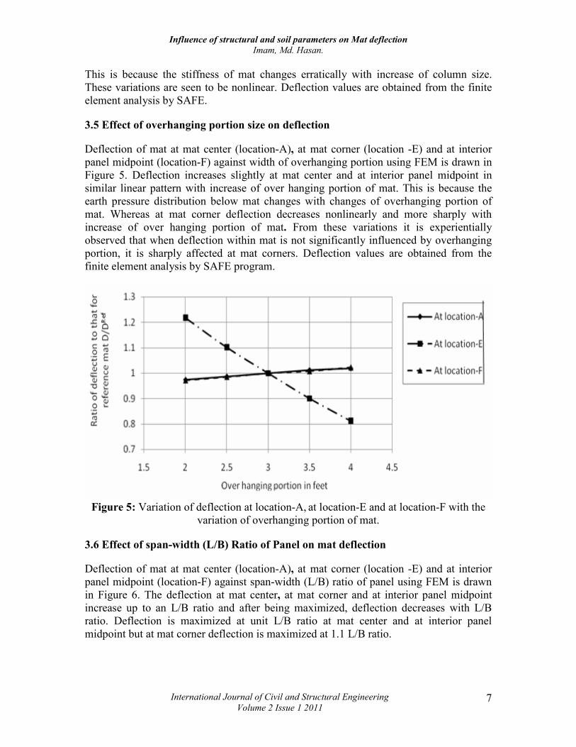
3.4 Effect of column size on deflection
Deflection of mat at mat center (location-A), at mat corner (location -E) and at interior
panel midpoint (location-F) against column size using FEM is drawn in Figure 4.
Deflection varies at mat center, at mat corner and at interior panel midpoint in similar
nonlinear sinusoidal pattern with increase of column size.
Figure 4: Variation of deflection at location-A, at location-E and at location-F with the
variation of column size.
Influence of structural and soil parameters on Mat deflection
Imam, Md. Hasan.
International Journal of Civil and Structural Engineering
Volume 2 Issue 1 2011 7
This is because the stiffness of mat changes erratically with increase of column size.
These variations are seen to be nonlinear. Deflection values are obtained from the finite
element analysis by SAFE.
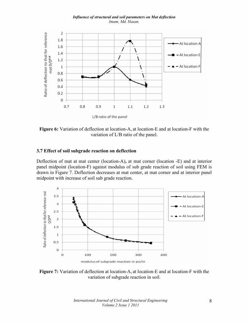
3.5 Effect of overhanging portion size on deflection
Deflection of mat at mat center (location-A), at mat corner (location -E) and at interior
panel midpoint (location-F) against width of overhanging portion using FEM is drawn in
Figure 5. Deflection increases slightly at mat center and at interior panel midpoint in
similar linear pattern with increase of over hanging portion of mat. This is because the
earth pressure distribution below mat changes with changes of overhanging portion of
mat. Whereas at mat corner deflection decreases nonlinearly and more sharply with
increase of over hanging portion of mat. From these variations it is experientially
observed that when deflection within mat is not significantly influenced by overhanging
portion, it is sharply affected at mat corners. Deflection values are obtained from the
finite element analysis by SAFE program.
Figure 5: Variation of deflection at location-A, at location-E and at location-F with the
variation of overhanging portion of mat.
3.6 Effect of span-width (L/B) Ratio of Panel on mat deflection
Deflection of mat at mat center (location-A), at mat corner (location -E) and at interior
panel midpoint (location-F) against span-width (L/B) ratio of panel using FEM is drawn
in Figure 6. The deflection at mat center, at mat corner and at interior panel midpoint
increase up to an L/B ratio and after being maximized, deflection decreases with L/B
ratio. Deflection is maximized at unit L/B ratio at mat center and at interior panel
midpoint but at mat corner deflection is maximized at 1.1 L/B ratio.
Influence of structural and soil parameters on Mat deflection
Imam, Md. Hasan.
International Journal of Civil and Structural Engineering
Volume 2 Issue 1 2011 8
Figure 6: Variation of deflection at location-A, at location-E and at location-F with the
variation of L/B ratio of the panel.
3.7 Effect of soil subgrade reaction on deflection
Deflection of mat at mat center (location-A), at mat corner (location -E) and at interior
panel midpoint (location-F) against modulus of sub grade reaction of soil using FEM is
drawn in Figure 7. Deflection decreases at mat center, at mat corner and at interior panel
midpoint with increase of soil sub grade reaction.
Figure 7: Variation of deflection at location-A, at location-E and at location-F with the
variation of subgrade reaction in soil.
Influence of structural and soil parameters on Mat deflection
Imam, Md. Hasan.
International Journal of Civil and Structural Engineering
Volume 2 Issue 1 2011 9
According to the definition the deflection is inversely proportional to the soil sub grade
reaction modulus (kS = ). This is because the stiffness of mat increases with increase of
soil sub grade reaction. In the figure the curves are nonlinear with negative and
decreasing slope. So the analysis values conform to the theoretical characteristics. These
values are obtained from the finite element analysis by SAFE.
4. Conclusions
A meticulous analytical and comparative study on effect of different structure parameters
and soil type on mat response is conducted in this work. In the light of the preceding
discussions the following conclusions may be drawn:
1. Deflection decreases at mat center and at mat corner with increasing mat
thickness. Deflection at interior panel mid point is, however seen to increase
with mat thickness. The variation is nonlinear in all cases.
2. Deflection at mat center increases and at interior panel center decreases with
column spacing. The variation of deflection at mat corner is sinusoidal with
column spacing.
3. Increase of column size shows a wavy effect on deflection.
4. Mat deflection within mat is not significantly influenced by overhanging
portion; it is sharply affected at mat corners.
5. Mat deflection shows a wavy (sinusoidal) character with changing of span-
width ratio of panel.
6. Mat deflection decreases nonlinearly with increasing modulus of sub-grade
reaction at all critical position.
5. References
1. ACI Committee 336(1966), “suggested design procedure for combined
Footings and Mats” (ACI 336.2R-66), Reaffirmed 1980, American concrete
Institute, Detroit, pp-13.
2. BNBC, 1993, “Combination of Loads for Strength Design Method”. part-6 :
pp. 67
3. Bowles, J.E (1974), Analytical and Computer Method in Foundation
Engineering, Mc Graw Hill Book Co., New York, NY10020.pp.128-145 and
207-253.
4. Bowles, J.E (1977), Foundation Analysis and Design, 5th Edition, Mc Graw
Hill Book Co., New York, NY10020.pp.501-506 and 537-588.
5. Coduto, Donald P. (2001), Foundation design: principles and practices,
Prentice Hall Pvt. Ltd. pp. 363-369.
Influence of structural and soil parameters on Mat deflection
Imam, Md. Hasan.
International Journal of Civil and Structural Engineering
Volume 2 Issue 1 2011 10
6. Curtin, William George; Seward,N. J.; Shaw,Gerry and Parkinson,Gary
(2006), Structural foundation designers' manual, Blackwell Publishing Asia
pty Ltd.
7. Design and Performance of Mat foundations - State of the Art Review, SP-
152, American Concrete Institute, Detroit, 1995.
8. Gupta, S. Chandra (2007), Raft Foundation Design And Analysis With A
Practical Approach, New Age International.
9. Imam,Syed Zubair (2003), Effect of Shear Wall on Behavior of Mat
Foundation.
10. Jumikis, A.R., Soil Mechanics and Foundation Engineering. ASCE, 1956.
11. Morshed, A.S.M. Monzurul (1996.), A Design Rationale for Mat Foundation
Based on Finite Element Analysis.
12. Nilson, A. H., D.Darwin, Dolan, C.W., (1943), Design of Concrete Structures-
13th Edition, Mc Graw Hill Book Co., New York, NY10020 pp 427-442.
13. Peck , R.B., Hanson , W.E., and Thornburn, T.H. (1974), Foundation
Engineering 2nd Edition , John Wiley & Sons , New York, pp.514.
14. Rahman, Syed Mizanur (2001), An Improved Design Approach for Mat
Foundation with Variable thickness.
15. Som , N. N. and Das , S. C. (2003), Theory and Practice of Foundation
Design, Prentice Hall Pvt. Ltd. New Delhi.
16. Technical reference, SAFE v8 Tutorial manual.
17. Teng, Wayne Chi-Yu (1962), Foundation Design, Prince-Hall Inc ,
Englewood Cliffs, pp. 151-154, 174-183, 189-191 and 466.
18. Timoshenko and Woinowsky – Krieger (1959), Theory of Plates and Shells.
19. Tomlinson, Michael John; Boorman, R. (2001), Foundation design and
construction, Prentice Hall Pvt. Ltd.
20. Varghese, P.C. (2005), Foundation Engineering, PHI Learning Pvt. Ltd.
Recommended


