TheHeat Tracing AuthorityTM
The History
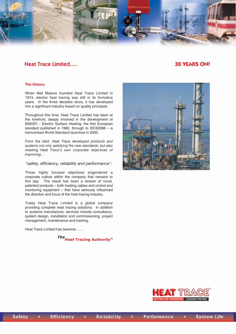
When Neil Malone founded Heat Trace Limited in 1974, electric heat tracing was still in its formative years. In the three decades since, it has developed into a significant industry based on quality principals.
Throughout this time, Heat Trace Limited has been at the forefront, deeply involved in the development of BS6351 - Electric Surface Heating, the first European standard published in 1982, through to IEC62086 – a harmonised World Standard launched in 2000.
From the start, Heat Trace developed products and systems not only satisfying the new standards, but also meeting Heat Trace’s own corporate objectives of improving…
"safety, efficiency, reliability and performance". These highly focused objectives engendered a corporate culture within the company that remains to this day. The result has been a stream of novel, patented products – both heating cables and control and monitoring equipment – that have seriously influenced the direction and focus of the heat tracing industry.
Today Heat Trace Limited is a global company providing complete heat tracing solutions. In addition to systems manufacture, services include consultancy, system design, installation and commissioning, project management, maintenance and training.
Heat Trace Limited has become……
The
Heat Tracing AuthorityTM
Heat Trace Limited..... 30 YEARS ON!
Heat Trace Limited..... Innovation
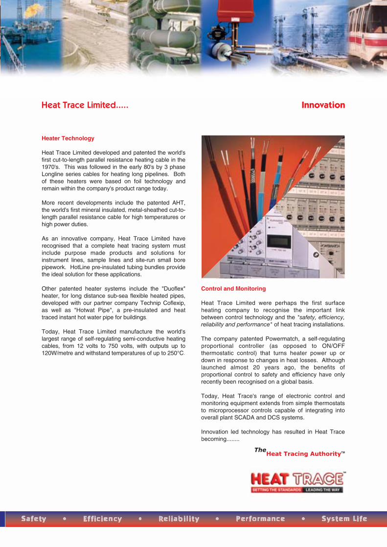
Heater Technology
Heat Trace Limited developed and patented the world's first cut-to-length parallel resistance heating cable in the1970's. This was followed in the early 80's by 3 phase Longline series cables for heating long pipelines. Both of these heaters were based on foil technology and remain within the company's product range today.
More recent developments include the patented AHT, the world's first mineral insulated, metal-sheathed cut-to-length parallel resistance cable for high temperatures or high power duties.
As an innovative company, Heat Trace Limited haverecognised that a complete heat tracing system must include purpose made products and solutions for instrument lines, sample lines and site-run small borepipework. HotLine pre-insulated tubing bundles provide the ideal solution for these applications.
Other patented heater systems include the "Duoflex" heater, for long distance sub-sea flexible heated pipes, developed with our partner company Technip Coflexip, as well as "Hotwat Pipe", a pre-insulated and heat traced instant hot water pipe for buildings.
Today, Heat Trace Limited manufacture the world's largest range of self-regulating semi-conductive heating cables, from 12 volts to 750 volts, with outputs up to 120W/metre and withstand temperatures of up to 250°C.
Control and Monitoring
Heat Trace Limited were perhaps the first surface heating company to recognise the important link between control technology and the "safety, efficiency, reliability and performance" of heat tracing installations.
The company patented Powermatch, a self-regulating proportional controller (as opposed to ON/OFF thermostatic control) that turns heater power up or down in response to changes in heat losses. Although launched almost 20 years ago, the benefits of proportional control to safety and efficiency have only recently been recognised on a global basis.
Today, Heat Trace's range of electronic control and monitoring equipment extends from simple thermostats to microprocessor controls capable of integrating into overall plant SCADA and DCS systems.
Innovation led technology has resulted in Heat Trace becoming........
The
Heat Tracing AuthorityTM
Heat Trace Limited..... Applications
COMMERCIAL
Commercial applications for heat tracing exist almost everywhere and systems may be found in domestic, municipal and institutional buildings; hospitals; nursing homes; office blocks; leisure complexes; educational establishments; etc.
Heat Trace can supply energy efficient systems for:• Freeze protection of pipes/tanks• Heating of hot water pipes• Floor warming• Roof and gutter heating for snow/ice prevention• Snow/ice prevention on roads/ramps/walkways/steps
& access areas, etc.• Heating fuel storage tanks
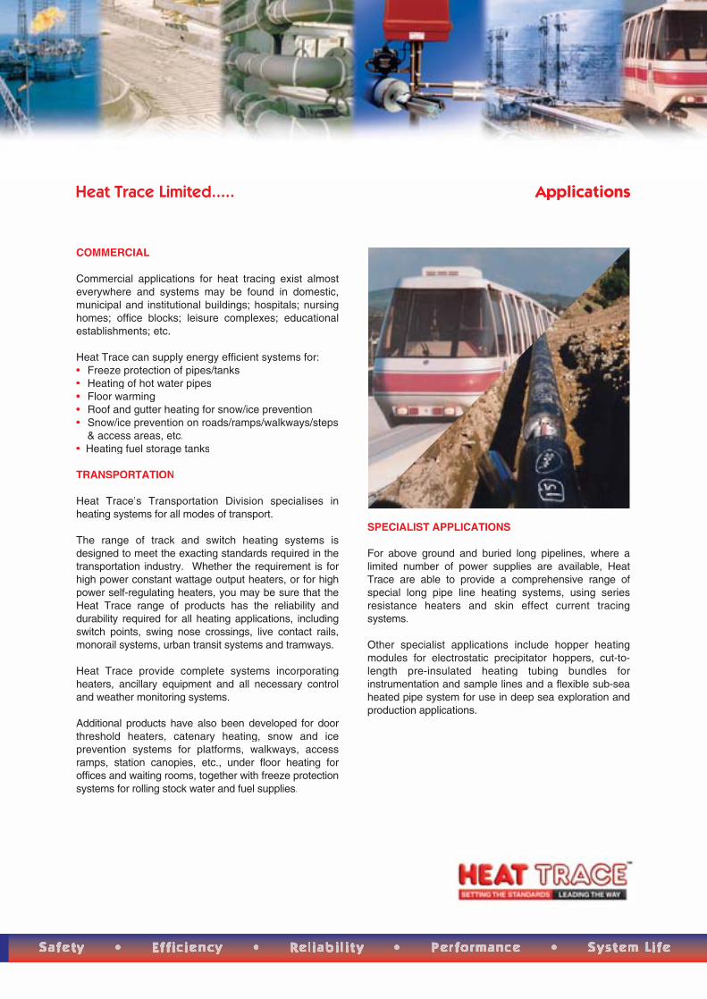
TRANSPORTATION
Heat Trace’s Transportation Division specialises in heating systems for all modes of transport.
The range of track and switch heating systems is designed to meet the exacting standards required in the transportation industry. Whether the requirement is for high power constant wattage output heaters, or for high power self-regulating heaters, you may be sure that the Heat Trace range of products has the reliability anddurability required for all heating applications, including switch points, swing nose crossings, live contact rails, monorail systems, urban transit systems and tramways.
Heat Trace provide complete systems incorporatingheaters, ancillary equipment and all necessary control and weather monitoring systems.
Additional products have also been developed for door threshold heaters, catenary heating, snow and ice prevention systems for platforms, walkways, access ramps, station canopies, etc., under floor heating for offices and waiting rooms, together with freeze protection systems for rolling stock water and fuel supplies.
SPECIALIST APPLICATIONS
For above ground and buried long pipelines, where a limited number of power supplies are available, Heat Trace are able to provide a comprehensive range of special long pipe line heating systems, using series resistance heaters and skin effect current tracing systems.
Other specialist applications include hopper heating modules for electrostatic precipitator hoppers, cut-to-length pre-insulated heating tubing bundles for instrumentation and sample lines and a flexible sub-sea heated pipe system for use in deep sea exploration and production applications.

Heat Trace Limited..... Applications
INDUSTRIAL
Electric heat tracingIndustrial applications may be found in oil and petro-chemical plants, refineries, pharmaceutical production, power generation, water and waste treatment plants, food processing, plus many others.
Heat Trace manufacture full heat tracing systems for:• Short or long pipelines• Complex in-plant piping systems• Above ground, buried, or sub-sea pipelines• Externally, or internally, traced pipelines• Safe, or hazardous area installations• Tanks and vessels• Hoppers• Instrumentation and sample lines• Instrument enclosures• Temperature maintenance, or heat raising to
temperatures up to 600°C.
Steam heat tracingSince the early 1900's, steam tracing has been the primary means of industrial heat tracing – even today 70%–of all industrial heat tracing systems are in fact steam.
Where steam supplies are available, steam for heat tracing is considered to be "free" surplus energy. However, steam tracing of pipe work and vessels is generally inefficient and difficult to control, when compared with electric heat tracing systems. Furthermore, no energy can be considered "free"!
Heat Trace can assist in ensuring that steam tracing system operate at their optimum efficiency.
For several decades, Heat Trace's thermal transfercompounds have been successfully aiding the efficiency of steam tracing systems around the world in petro-chemical, processing, power generation and other strategic industries.
Heat Trace's thermal transfer compounds cover temperatures up to 600°C. Additional low temperature "flexible" compounds complete a comprehensive product line capability.
OFFSHORE
In the harsh offshore environment safety and reliability are high priorities. Heat Trace are able to supply high quality products and services to meet the demands of the industry. Flexible sub-sea heated pipelines, heated riser systems, topside pipeline heating (freeze protection and temperature maintenance) helicopter platform snow and ice prevention systems - these are just some of the application solutions available from Heat Trace Limited.
Heat Trace Limited..... Research & Development
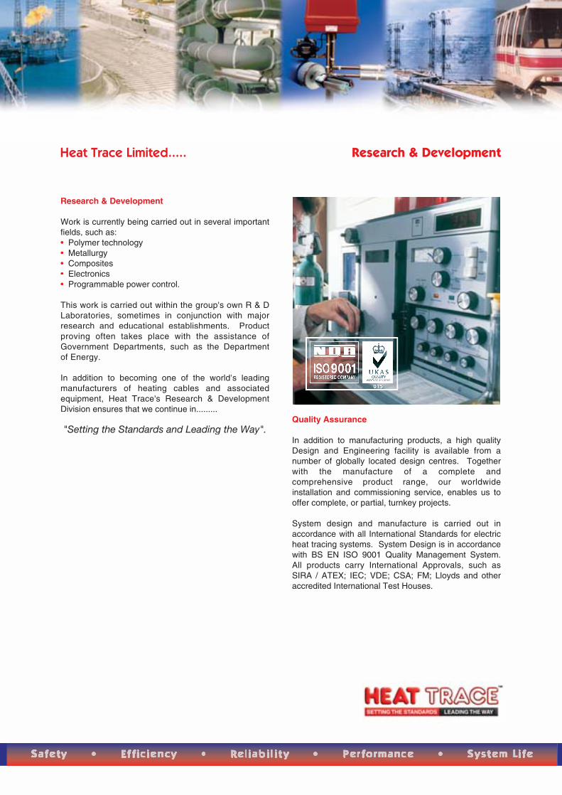
Research & Development
Work is currently being carried out in several important fields, such as: • Polymer technology• Metallurgy• Composites• Electronics• Programmable power control.
This work is carried out within the group's own R & D Laboratories, sometimes in conjunction with major research and educational establishments. Product proving often takes place with the assistance of Government Departments, such as the Department of Energy.
In addition to becoming one of the world’s leading manufacturers of heating cables and associated equipment, Heat Trace's Research & Development Division ensures that we continue in.........
"Setting the Standards and Leading the Way".Quality Assurance
In addition to manufacturing products, a high quality Design and Engineering facility is available from a number of globally located design centres. Together with the manufacture of a complete and comprehensive product range, our worldwide installation and commissioning service, enables us to offer complete, or partial, turnkey projects.
System design and manufacture is carried out in accordance with all International Standards for electric heat tracing systems. System Design is in accordance with BS EN ISO 9001 Quality Management System. All products carry International Approvals, such as SIRA / ATEX; IEC; VDE; CSA; FM; Lloyds and other accredited International Test Houses.
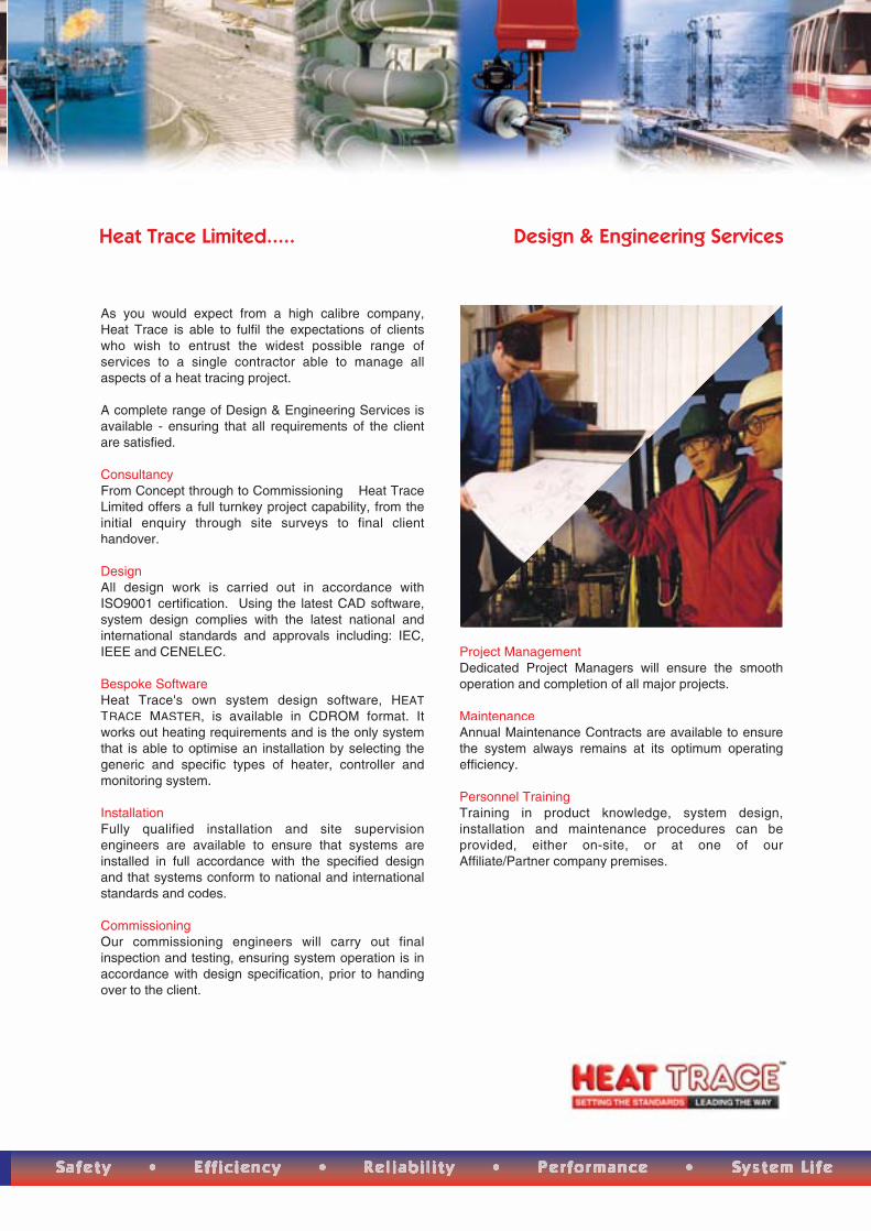
As you would expect from a high calibre company, Heat Trace is able to fulfil the expectations of clients who wish to entrust the widest possible range of services to a single contractor able to manage allaspects of a heat tracing project.
A complete range of Design & Engineering Services is available - ensuring that all requirements of the client are satisfied.
ConsultancyFrom Concept through to Commissioning – Heat Trace Limited offers a full turnkey project capability, from the initial enquiry through site surveys to final clienthandover.
DesignAll design work is carried out in accordance with ISO9001 certification. Using the latest CAD software, system design complies with the latest national and international standards and approvals including: IEC, IEEE and CENELEC.
Bespoke SoftwareHeat Trace's own system design software, HEATTRACE MASTER, is available in CDROM format. It works out heating requirements and is the only system that is able to optimise an installation by selecting the generic and specific types of heater, controller and monitoring system.
InstallationFully qualified installation and site supervision engineers are available to ensure that systems are installed in full accordance with the specified design and that systems conform to national and international standards and codes.
CommissioningOur commissioning engineers will carry out final inspection and testing, ensuring system operation is in accordance with design specification, prior to handing over to the client.
Project ManagementDedicated Project Managers will ensure the smooth operation and completion of all major projects.
MaintenanceAnnual Maintenance Contracts are available to ensure the system always remains at its optimum operating efficiency.
Personnel TrainingTraining in product knowledge, system design, installation and maintenance procedures can be provided, either on-site, or at one of our Affiliate/Partner company premises.
Heat Trace Limited..... Design & Engineering Services

WORLDWIDE REPRESENTATION
Heat Trace is represented throughout the world in over 30 countries. Our network of Affiliate Offices, Partner Companies, Distributors and Agents work, both independently and jointly, with our Corporate Headquarters, resulting in an integrated team of heat tracing and surface heating specialists having a global capability. For full details of overseas offices please see our Website at www.heat-trace.com or contact Heat Trace Limited direct
Tracer House, Cromwell Road, Bredbury, Stockport, Cheshire SK6 2RF, UK.Tel: +44 (0)161-430 8333 Fax: +44 (0)161-430 8654 www.heat-trace.com

Project Objective
To demonstrate the energy savings achiev-able in electrical trace heating circuits byusing solid state controllers in conjunctionwith, or instead of, conventional on-off ther-mostats.
Potential Use rs
Operators of processes requiring electricaltrace heating.
Investment Cost
£2,750/km (Power matching controller)£2,500/km (Proportional controller)
Annual S avings Achi eved
£6,343/km (Power matching controller)£6,976/km (Proportional controller)
Payback Period
23 weeks (Power matching controller)19 weeks (Proportional controller)
Project Summary
Trace heating is necessary to assist theflow within pipes carrying fluids which havea high viscosity at average UK ambienttemperatures. The heating is usually con-trolled via an on-off thermostat. The use ofmore sophisticated solid state equipmentwas tested, both in conjunction with, andinstead of, conventional on-off thermostatsin existing electrical trace heating systems.The performance of two solid-state sys-tems was compared with that of a conven-tional on-off thermostat. The systems were:
a self-regulating, air sensing, powermatching controller which was added toexisting surface thermostats.
a surface sensing proportional controllerwhich replaced conventional ther-mostats;
The trials were conducted on a single six-inch diameter pipe carrying benzene.Three zones of the pipe were chosen; oneto test the power matching controllerarrangement; one to test the proportionalcontroller; and one with the original equip-ment to act as control.
The savings achieved were much greaterthan anticipated.
Host O rganisation
BP Oil Grangemouth Refinery LimitedBo'ness RoadGrangemouthStirlingshireFK3 9XQ
Monitoring Contractor
NIFES Consulting Group8 Woodside TerraceGlasgowG3 7UYTel No: 0141 332 2453Fax No: 0141 333 0402Mr A L Hannah
Equipment Manufacturer
Heat Trace LtdTracer HouseCromwell RoadBredburyStockportSK6 2RFTel No: 0161 430 8333Fax No: 0161 430 8654Mr N S Malone
N e w P r a c t i c e
Final Profile 44Energy efficient control systems forelectrical trace heating circuits
Pipeline installation at BP Oil Grangemouth Refinery Ltd
B E S T P R A C T I C E P R O G R A M M E
“ The savings achieved were much greaterthan anticipated ”
The Organisation
BP Oil Grangemouth Refinery Limited pro-vided an ideal location for the comparativemonitoring of the systems. A single six-inchdiameter pipe carries Benzene three kilo-meters from the production plant, in the BPChemicals complex, to the Jetty Storagearea at Grangemouth docks. BP Oil isresponsible for maintaining an adequatepipeline temperature along the majority ofthe three kilometers.
Background
The operation of the refinery and its satellitesites relies on electrical trace heating tofacilitate proper flow through the pipelines.At Grangemouth, the required minimumtemperature is 21oC. The energy demand-ed by the system or equipment dependson the operation of simple on-off ther-mostats which react to pipeline tempera-tures.
In such circumstances the system rating isdesigned with large margins to cover set-points to overcome the limitations of simpleon-off controls, provides considerablepotential for energy wastage.
Plant Modifications
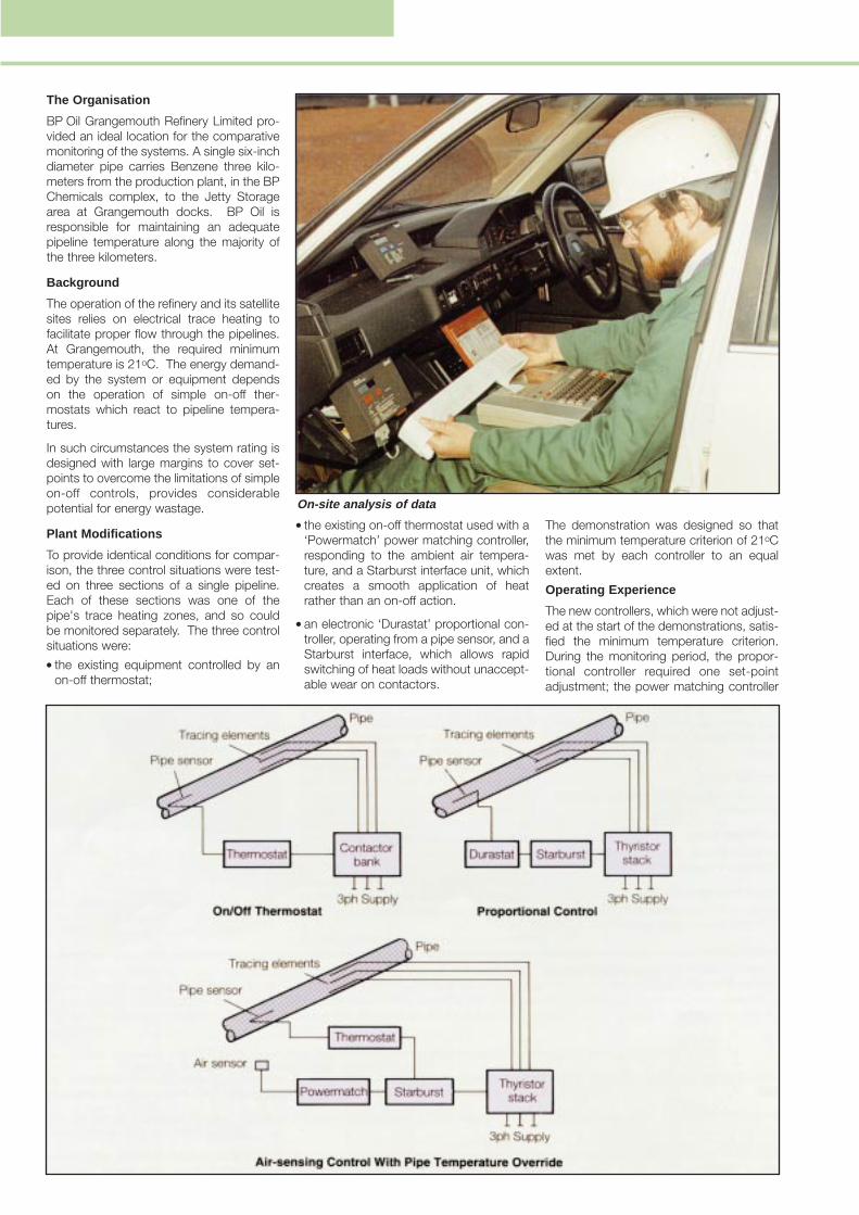
To provide identical conditions for compar-ison, the three control situations were test-ed on three sections of a single pipeline.Each of these sections was one of thepipe's trace heating zones, and so couldbe monitored separately. The three controlsituations were: the existing equipment controlled by an
on-off thermostat;
the existing on-off thermostat used with a‘Powermatch’ power matching controller,responding to the ambient air tempera-ture, and a Starburst interface unit, whichcreates a smooth application of heatrather than an on-off action.
an electronic ‘Durastat’ proportional con-troller, operating from a pipe sensor, and aStarburst interface, which allows rapidswitching of heat loads without unaccept-able wear on contactors.
The demonstration was designed so thatthe minimum temperature criterion of 21oCwas met by each controller to an equalextent.
Operating Experience
The new controllers, which were not adjust-ed at the start of the demonstrations, satis-fied the minimum temperature criterion.During the monitoring period, the propor-tional controller required one set-pointadjustment; the power matching controller
On-site analysis of data
required none. It is possible that the per-formance of the power matching controllercould have been improved by on-site cali-bration, but in this case, it was left in its fac-tory-set state.
At the start of the demonstration, the exist-ing thermostatically controlled circuit wasfound to be wrongly connected and wastherefore reset. The thermostat then per-mitted temperatures to drop to 16oC,requiring the set-point to be altered toreach an apparent 27.5oC, actual 25oC, toovercome this problem.
Monitoring
Monitoring lasted from 3rd August 1989 to15th February 1990 and was concernedwith two situations, static fluid and a com-bination of free flowing and static fluid,described as the ‘overall’ situation.
Energy Savings
The demonstration showed that substantialsavings could be achieved by both thepower matching and proportional con-trollers with the savings in the overall situa-tion greater than those in the static fluid sit-uation.
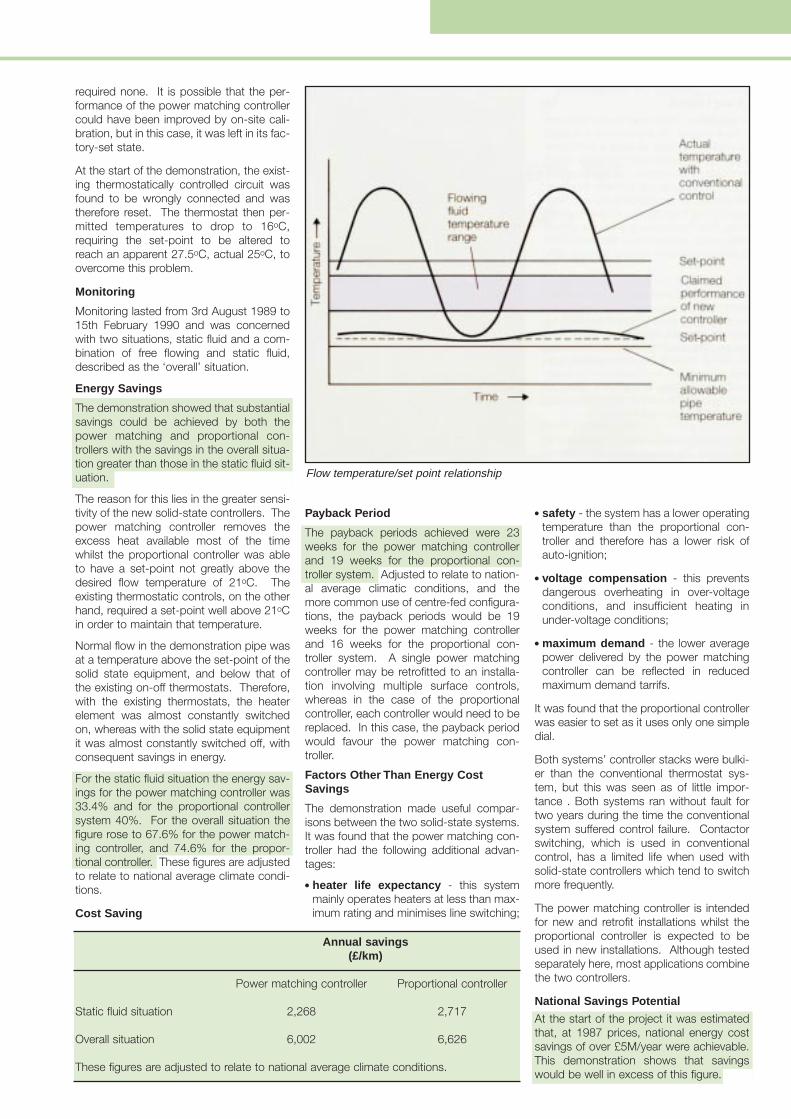
The reason for this lies in the greater sensi-tivity of the new solid-state controllers. Thepower matching controller removes theexcess heat available most of the timewhilst the proportional controller was ableto have a set-point not greatly above thedesired flow temperature of 21oC. Theexisting thermostatic controls, on the otherhand, required a set-point well above 21oCin order to maintain that temperature.
Normal flow in the demonstration pipe wasat a temperature above the set-point of thesolid state equipment, and below that ofthe existing on-off thermostats. Therefore,with the existing thermostats, the heaterelement was almost constantly switchedon, whereas with the solid state equipmentit was almost constantly switched off, withconsequent savings in energy.
For the static fluid situation the energy sav-ings for the power matching controller was33.4% and for the proportional controllersystem 40%. For the overall situation thefigure rose to 67.6% for the power match-ing controller, and 74.6% for the propor-tional controller. These figures are adjustedto relate to national average climate condi-tions.
Cost Saving
Payback Period
The payback periods achieved were 23weeks for the power matching controllerand 19 weeks for the proportional con-troller system. Adjusted to relate to nation-al average climatic conditions, and themore common use of centre-fed configura-tions, the payback periods would be 19weeks for the power matching controllerand 16 weeks for the proportional con-troller system. A single power matchingcontroller may be retrofitted to an installa-tion involving multiple surface controls,whereas in the case of the proportionalcontroller, each controller would need to bereplaced. In this case, the payback periodwould favour the power matching con-troller.
Factors Other Than Energy CostSavings
The demonstration made useful compar-isons between the two solid-state systems.It was found that the power matching con-troller had the following additional advan-tages:
heater life expectancy - this systemmainly operates heaters at less than max-imum rating and minimises line switching;
safety - the system has a lower operatingtemperature than the proportional con-troller and therefore has a lower risk ofauto-ignition;
voltage compensation - this preventsdangerous overheating in over-voltageconditions, and insufficient heating inunder-voltage conditions;
maximum demand - the lower averagepower delivered by the power matchingcontroller can be reflected in reducedmaximum demand tarrifs.
It was found that the proportional controllerwas easier to set as it uses only one simpledial.
Both systems’ controller stacks were bulki-er than the conventional thermostat sys-tem, but this was seen as of little impor-tance . Both systems ran without fault fortwo years during the time the conventionalsystem suffered control failure. Contactorswitching, which is used in conventionalcontrol, has a limited life when used withsolid-state controllers which tend to switchmore frequently.
The power matching controller is intendedfor new and retrofit installations whilst theproportional controller is expected to beused in new installations. Although testedseparately here, most applications combinethe two controllers.
National Savings Potential
At the start of the project it was estimatedthat, at 1987 prices, national energy costsavings of over £5M/year were achievable.This demonstration shows that savingswould be well in excess of this figure.
Annual savings(£/km)
Power matching controller Proportional controller
Static fluid situation 2,268 2,717
Overall situation 6,002 6,626
These figures are adjusted to relate to national average climate conditions.
Flow temperature/set point relationship

Comments from BP Oil GrangemouthRefinery Limited
The installation of the new control schemesfor trace heating on a process line locatedin an operating plant allowed a valid com-parison to be made with a simple on/offthermostatic controller. Monitoring theprocess conditions and ambient tempera-tures allowed an analysis of the power con-sumed by the trace heating for each type ofcontrol. The results clearly show the energysavings which resulted from the use of bothproportional control and air-sensing con-trol.
In addition to the energy savings, pipe tem-perature control was improved withreduced variations in temperature, and themaximum demand for electrical power wasreduced. The improved temperature con-trol may be of benefit for some processeswhich are sensitive to extremes of temper-ature. The reduction in maximum demandcould reduce the capital expenditure onelectrical distribution equipment.
In conclusion, this study was able todemonstrate the advantages of proportion-al control and air sensing control over themore conventional on/off thermostatic con-trol. The value of the study has beenenhanced by being carried out on an oper-ating plant over a significant period of time.
Mr D AtkinsonLead Electrical EngineerBP Oil Grangemouth Refinery Limited
BP Oil Grangemouth Refinery Limited
BP Oil Grangemouth Refinery Limited oper-ates BP Group’s only UK crude oil refiningfacility, producing a full range of petroleumproducts. The refinery lies on the southernbank of the upper reaches of the Firth ofForth and has been a key feature ofScotland’s industrial scene for most of thiscentury.
BP Oil Grangemouth Refinery Limited
The work described here was carried out under the Energy Efficiency Demonstration Scheme. The Energy Efficiency Office hasreplaced the Demonstration Scheme by the Best Practice programme which is aimed at advancing and disseminating impartialinformation to help improve energy efficiency. Results from the Demonstration Scheme will continue to be promoted. However, newprojects can only be considered for support under the Best Practice programme. More detailed information on this project iscontained in the final report NP/40.
For further copies of this publication or other Best Practice programme literature please contact BRECSU or ETSU.
For buildings-related projects: Enquiries Bureau, Building Research Energy Conservation Support Unit (BRECSU),Building Research Establishment, Garston, Watford, WD2 7JR. Tel No: 0923 664258. Fax No: 0923 664097.
For industrial projects: Energy Efficiency Enquiries Bureau, ETSU, Harwell, Oxfordshire OX11 0RA. Tel No: 0235 436747.Telex 83135. Fax No: 0235 432923.
Information on participation in the Best Practice programme and on energy efficiency generally is also available from yourRegional Energy Efficiency Office.
(C) Crown Copyright. First Printed June 1994
FREEZSTOPMICRO
Self-Regulating Heating Tape
FSMElectrical heating tape for frost protection ortemperature maintenance of instrument lines andpipework in safe or hazardous locations
FEATURES
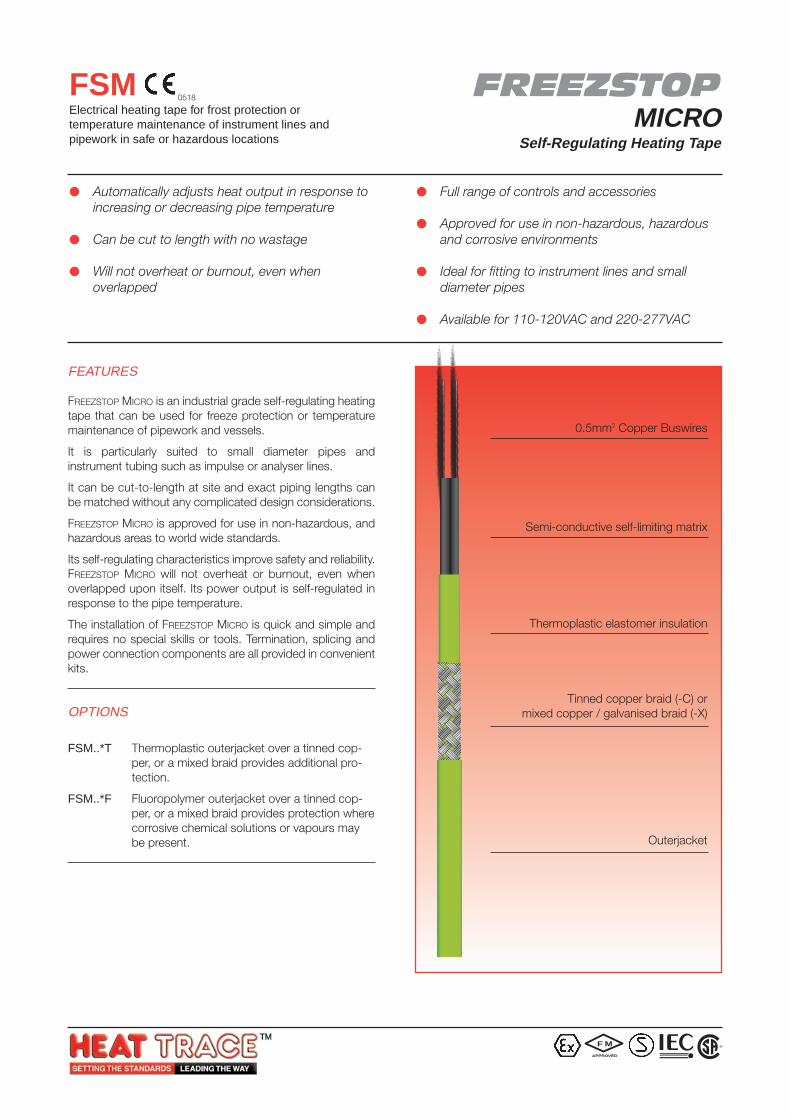
FREEZSTOP MICRO is an industrial grade self-regulating heatingtape that can be used for freeze protection or temperaturemaintenance of pipework and vessels.
It is particularly suited to small diameter pipes andinstrument tubing such as impulse or analyser lines.
It can be cut-to-length at site and exact piping lengths canbe matched without any complicated design considerations.
FREEZSTOP MICRO is approved for use in non-hazardous, andhazardous areas to world wide standards.
Its self-regulating characteristics improve safety and reliability.FREEZSTOP MICRO will not overheat or burnout, even whenoverlapped upon itself. Its power output is self-regulated inresponse to the pipe temperature.
The installation of FREEZSTOP MICRO is quick and simple andrequires no special skills or tools. Termination, splicing andpower connection components are all provided in convenientkits.
OPTIONS
FSM..*T Thermoplastic outerjacket over a tinned cop-per, or a mixed braid provides additional pro-tection.
FSM..*F Fluoropolymer outerjacket over a tinned cop-per, or a mixed braid provides protection wherecorrosive chemical solutions or vapours maybe present.
Automatically adjusts heat output in response toincreasing or decreasing pipe temperature
Can be cut to length with no wastage
Will not overheat or burnout, even whenoverlapped
Full range of controls and accessories
Approved for use in non-hazardous, hazardousand corrosive environments
Ideal for fitting to instrument lines and smalldiameter pipes
Available for 110-120VAC and 220-277VAC
0.5mm2 Copper Buswires
Semi-conductive self-limiting matrix
Thermoplastic elastomer insulation
Tinned copper braid (-C) ormixed copper / galvanised braid (-X)
Outerjacket
0518
F M
APPROVED
R
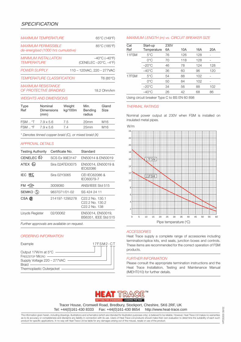
MAXIMUM LENGTH (m) vs. CIRCUIT BREAKER SIZE
Cat Start-up 230VRef Temperature 6A 10A 16A 20A11FSM 5°C 76 126 128 -
0°C 70 118 128 -
–20°C 46 78 124 128
–40°C 36 60 96 120
17FSM 5°C 54 88 102 -
0°C 50 84 102 -
–20°C 34 56 88 102
–40°C 26 42 68 86
Using circuit breaker Type C to BS EN 60 898
THERMAL RATINGS
Nominal power output at 230V when FSM is installed oninsulated metal pipes.
ACCESSORIESHeat Trace supply a complete range of accessories includingtermination/splice kits, end seals, junction boxes and controls.These items are recommended for the correct operation of FSMproducts.
FURTHER INFORMATIONPlease consult the appropriate termination instructions and theHeat Trace Installation, Testing and Maintenance Manual(IMEHT010) for further details.
SPECIFICATION
Tracer House, Cromwell Road, Bredbury, Stockport, Cheshire, SK6 2RF, UKTel: +44(0)161-430 8333 Fax: +44(0)161-430 8654 http://www.heat-trace.com
The information given herein, including drawings, illustrations and schematics (which are intended for illustration purposes only), is believed to be reliable. However, Heat Trace Ltd makes no warrantiesas to its accuracy or completeness and disclaims any liability in connection with its use. Users of Heat Trace Ltd products should make their own evaluation to determine the suitability of each suchproduct for specific applications. In no way will Heat Trace Ltd be liable for any damages arising out of the misuse, resale or use of the product.
HP
DS
300
08/0
2
MAXIMUM TEMPERATURE 65°C (149°F)
MAXIMUM PERMISSIBLE 85°C (185°F)de-energised (1000 hrs cumulative)
MINIMUM INSTALLATION –40°C (–40°F)TEMPERATURE (CENELEC –20°C, –4°F)
POWER SUPPLY 110 – 120VAC, 220 – 277VAC
TEMPERATURE CLASSIFICATION T6 (85°C)
MAXIMUM RESISTANCEOF PROTECTIVE BRAIDING 18.2 Ohm/km
WEIGHTS AND DIMENSIONS
Type Nominal Weight Min. GlandRef Dimensions kg/100m Bending Size
(mm) radius
FSM .. *T 7.9 x 5.6 7.5 20mm M16
FSM .. *F 7.9 x 5.6 7.4 25mm M16
* Denotes tinned copper braid (C), or mixed braid (X)
APPROVAL DETAILS
Testing Authority Certificate No. Standard
CENELEC SCS Ex 99E3147 EN50014 & EN50019
ATEX Sira 02ATEX3075 EN50014, EN50019 &IEC62086
IEC Sira 02Y3065 CEI IEC62086 &IEC60079-7
FM 3009080 ANSI/IEEE Std 515
SEMKO 9837071/01-02 SS 424 24 11
CSA 214197-1295278 C22.2 No. 130.1C22.2 No. 130.2C22.2 No. 138
Lloyds Register 02/00062 EN50014, EN50019,BS6351, IEEE Std 515
Further approvals are available on request.
ORDERING INFORMATION
Example 17F S M 2 - C T
Output 17W/m at 5°CFREEZSTOP MICRO
Supply Voltage 220 – 277VACBraidThermoplastic Outerjacket
0 5
2
4
6
8
10
12
14
18
20
22
24
16
10 15 20 25 30 35 40 45 6050 55
17FSM
11FSM
W/m
Pipe temperature (oC)
F M
APPROVED
R
FREEZSTOPLITE
Self-Regulating Heating Tape
FSLeElectrical heating tape for frost protection ortemperature maintenance of instrument lines andpipework in safe or hazardous locations
FEATURES
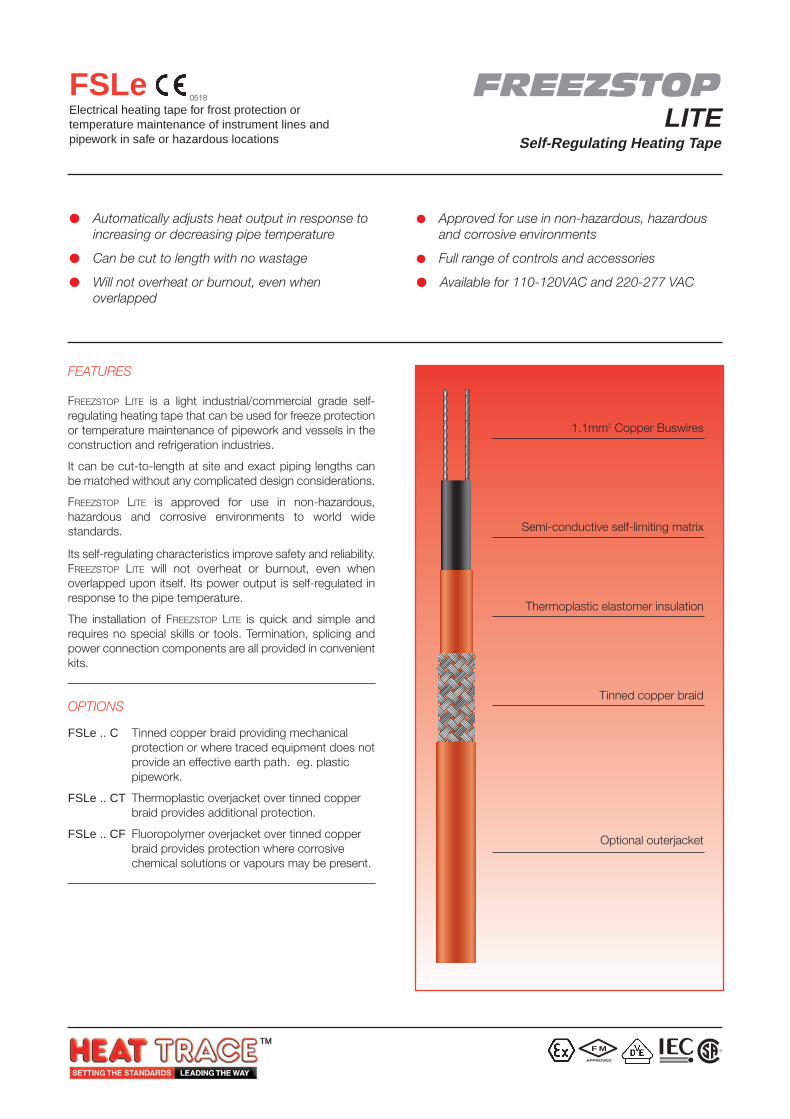
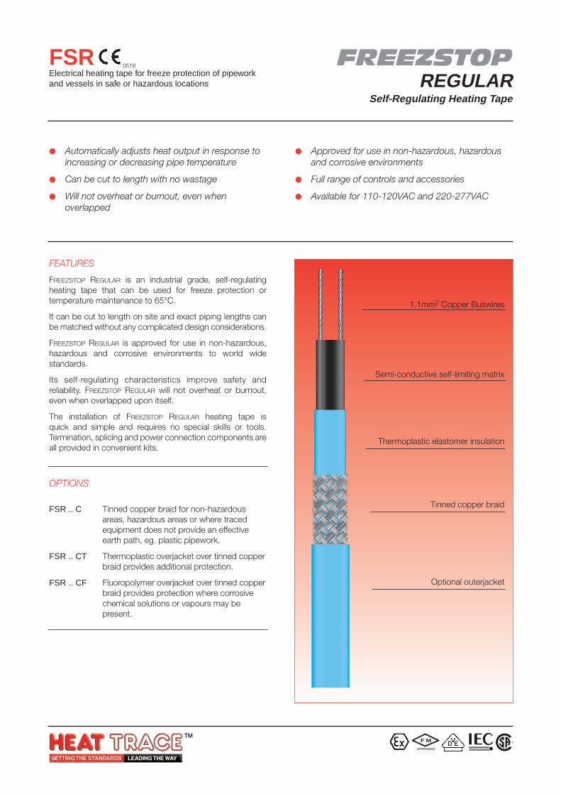
FREEZSTOP LITE is a light industrial/commercial grade self-regulating heating tape that can be used for freeze protectionor temperature maintenance of pipework and vessels in theconstruction and refrigeration industries.
It can be cut-to-length at site and exact piping lengths canbe matched without any complicated design considerations.
FREEZSTOP LITE is approved for use in non-hazardous,hazardous and corrosive environments to world widestandards.
Its self-regulating characteristics improve safety and reliability.FREEZSTOP LITE will not overheat or burnout, even whenoverlapped upon itself. Its power output is self-regulated inresponse to the pipe temperature.
The installation of FREEZSTOP LITE is quick and simple andrequires no special skills or tools. Termination, splicing andpower connection components are all provided in convenientkits.
OPTIONS
FSLe .. C Tinned copper braid providing mechanicalprotection or where traced equipment does notprovide an effective earth path. eg. plasticpipework.
FSLe .. CT Thermoplastic overjacket over tinned copperbraid provides additional protection.
FSLe .. CF Fluoropolymer overjacket over tinned copperbraid provides protection where corrosivechemical solutions or vapours may be present.
Automatically adjusts heat output in response toincreasing or decreasing pipe temperature
Can be cut to length with no wastage
Will not overheat or burnout, even whenoverlapped
Approved for use in non-hazardous, hazardousand corrosive environments
Full range of controls and accessories
Available for 110-120VAC and 220-277 VAC
1.1mm2 Copper Buswires
Semi-conductive self-limiting matrix
Thermoplastic elastomer insulation
Tinned copper braid
Optional outerjacket
F M
APPROVED
0518
R
0 5
3
6
9
12
15
18
21
27
30
33
36
24
10 15 20 25 30 35 40 45 6050 55
31FSLe
23FSLe
17FSLe
12FSLe
MAXIMUM TEMPERATURE 65°C (149°F)
MAX. PERMISSIBLE TEMPERATURE 85°C (185°F)de-energised (1000 hrs cumulative)
MINIMUM INSTALLATION –40°C (–40°F)TEMPERATURE (CENELEC –20°C, –4°F)
POWER SUPPLY 110 – 120VAC, 220 – 277VAC
TEMPERATURE up to 23W/m T6 (85°C)CLASSIFICATION 31W/m and/or 277V T4 (135°C)
MAXIMUM RESISTANCEOF PROTECTIVE BRAIDING 18.2 Ohm/km
WEIGHTS AND DIMENSIONS
Type Nominal Weight Min. GlandRef Dimensions kg/100m Bending Size
(mm) radius
FSLe 8.5 x 3.9 4.6 25mm M20
FSLe .. C 9.3 x 4.7 9.2 30mm M20
FSLe .. CT 10.5 x 5.9 10.2 35mm M20
FSLe .. CF 10.5 x 5.9 9.9 35mm M20
APPROVAL DETAILS
Testing Authority Certificate No. Standard
CENELEC SCS Ex 99E3146 EN50014 & EN50019
ATEX Sira 02ATEX3074 EN50014, EN50019 &IEC62086
IEC Sira 02Y3064 CEI IEC62086 &IEC60079-7
FM 3009080 ANSI/IEEE Std 515
VDE 114665 DIN VDE 0254
CSA 214197-1295278 C22.2 No. 130.1C22.2 No. 130.2C22.2 No. 138
Lloyds Register 02/00062 EN50014, EN50019,BS6351, IEEE Std 515
Further approvals are available on request.
ORDERING INFORMATION
Example 12F S L e 2 - C T
Output 12W/m at 5°CFREEZSTOP LITE
Supply Voltage 220 – 277VACTinned Copper BraidThermoplastic Outerjacket
ACCESSORIESHeat Trace supply a complete range of accessories includingtermination/splice kits, end seals, junction boxes and controls.These items are recommended for the correct operation of FSLeproducts.
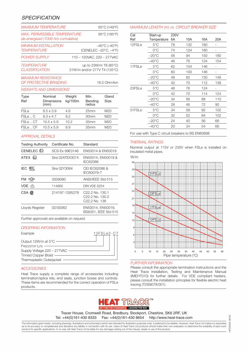
MAXIMUM LENGTH (m) vs. CIRCUIT BREAKER SIZE
Cat Start-up 230VRef Temperature 6A 10A 16A 20A12FSLe 5°C 78 132 180 -
0°C 74 124 180 -
–20°C 56 94 150 180
–40°C 46 76 124 154
17FSLe 5°C 62 104 146 -
0°C 60 100 146 -
–20°C 48 82 130 146
–40°C 42 70 112 138
23FSLe 5°C 46 76 124 -
0°C 42 70 114 124
–20°C 34 56 88 110
–40°C 28 46 72 90
31FSLe 5°C 34 58 92 102
0°C 32 52 84 102
–20°C 24 40 56 66
–40°C 20 34 54 66
For use with Type C circuit breakers to BS EN60898
THERMAL RATINGSNominal output at 115V or 230V when FSLe is installed oninsulated metal pipes.
SPECIFICATION
Tracer House, Cromwell Road, Bredbury, Stockport, Cheshire, SK6 2RF, UKTel: +44(0)161-430 8333 Fax: +44(0)161-430 8654 http://www.heat-trace.com
The information given herein, including drawings, illustrations and schematics (which are intended for illustration purposes only), is believed to be reliable. However, Heat Trace Ltd makes no warrantiesas to its accuracy or completeness and disclaims any liability in connection with its use. Users of Heat Trace Ltd products should make their own evaluation to determine the suitability of each suchproduct for specific applications. In no way will Heat Trace Ltd be liable for any damages arising out of the misuse, resale or use of the product.
HP
DS
350
08/0
2
W/m
Pipe temperature (oC)
FURTHER INFORMATIONPlease consult the appropriate termination instructions and theHeat Trace Installation, Testing and Maintenance Manual(IMEHT010) for further details. For VDE compliant heaters,please consult the installation principles for flexible electric heattracing (TDS9078/001).
F M
APPROVED
R
Automatically adjusts heat output in response toincreasing or decreasing pipe temperature
Can be cut to length with no wastage
Will not overheat or burnout, even whenoverlapped
Approved for use in non-hazardous, hazardousand corrosive environments
Full range of controls and accessories
Available for 110-120VAC and 220-277VAC
FEATURES
FREEZSTOP REGULAR is an industrial grade, self-regulatingheating tape that can be used for freeze protection ortemperature maintenance to 65°C.
It can be cut to length on site and exact piping lengths canbe matched without any complicated design considerations.
FREEZSTOP REGULAR is approved for use in non-hazardous,hazardous and corrosive environments to world widestandards.
Its self-regulating characteristics improve safety andreliability. FREEZSTOP REGULAR will not overheat or burnout,even when overlapped upon itself.
The installation of FREEZSTOP REGULAR heating tape isquick and simple and requires no special skills or tools.Termination, splicing and power connection components areall provided in convenient kits.
OPTIONS
FSR .. C Tinned copper braid for non-hazardousareas, hazardous areas or where tracedequipment does not provide an effectiveearth path, eg. plastic pipework.
FSR .. CT Thermoplastic overjacket over tinned copperbraid provides additional protection.
FSR .. CF Fluoropolymer overjacket over tinned copperbraid provides protection where corrosivechemical solutions or vapours may bepresent.
FREEZSTOPREGULAR
Self-Regulating Heating Tape
FSRElectrical heating tape for freeze protection of pipeworkand vessels in safe or hazardous locations
1.1mm2 Copper Buswires
Semi-conductive self-limiting matrix
Thermoplastic elastomer insulation
Tinned copper braid
Optional outerjacket
F M
APPROVED
R
0518
MAXIMUM TEMPERATURE 65°C (150°F)
MAX. PERMISSIBLE TEMPERATURE 85°C (185°F)de-energised (1000 hrs cumulative)
MINIMUM INSTALLATION –40°C (–40°F)TEMPERATURE (CENELEC –20°C,–4°F)
TEMPERATURE up to 31 W/m T6 (85°C)CLASSIFICATION 40 W/m and/or 277V T4 (135°C)
POWER SUPPLY 110 – 120VAC, 220 – 277VAC
MAXIMUM RESISTANCEOF PROTECTIVE BRAIDING 18.2 Ohm/km
WEIGHTS & DIMENSIONS
Type Nom. Dims. Weight Min. Bending GlandRef (mm) kg/100m radius Size
FSR 10.9 x 3.8 5.8 25 mm M20
FSR .. C 11.8 x 4.7 11.2 30 mm M20
FSR .. CT 13.1 x 6.0 13.1 35 mm M20
FSR .. CF 13.1 x 6.0 13.4 35 mm M20
APPROVAL DETAILS
Testing Authority Certificate No. Standard
CENELEC SCS Ex 94D3079 EN50014 & EN50019
ATEX Sira 02ATEX3070 EN50014, EN50019 &IEC62086
IEC Sira 02Y3060 CEI IEC62086 &IEC60079-7
FM 3009080 ANSI/IEEE Std 515
VDE 114665 DIN VDE 0254
CSA 214197-1295278 C22.2 No. 130.1C22.2 No. 130.2C22.2 No. 138
Lloyds Register 02/00062 EN50014, EN50019,BS6351, IEEE Std 515
Further approvals are available on request.
ORDERING INFORMATION
Example 17FSR2-CT
Output 17W/m at 10°CFREEZSTOP REGULAR
Supply Voltage 220 - 277V ACTinned Copper BraidThermoplastic Outerjacket
ACCESSORIES
Heat Trace supply a complete range of accessories includingtermination/splice kits, end seals, junction boxes and controls.Such items carry separate approvals from the heating tapes.When used in hazardous areas, only use approved components.
SPECIFICATION
0 5
4
8
12
16
20
24
28
36
40
44
48
32
10 15 20 25 30 35 40 45 6050 55
40FSR
31FSR
25FSR
17FSR
10FSR
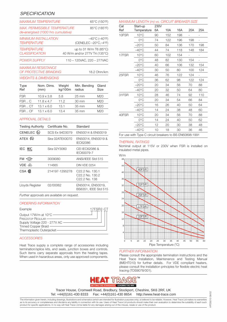
MAXIMUM LENGTH (m) vs. CIRCUIT BREAKER SIZECat Start-up 230VRef Temperature 6A 10A 16A 20A 25A10FSR 10°C 90 152 198 - -
0°C 74 122 196 198 -
–20°C 50 84 136 170 198
–40°C 44 74 118 148 184
17FSR 10°C 60 102 154 - -
0°C 48 82 130 154 -
–20°C 40 66 106 132 154
–40°C 30 50 80 100 124
25FSR 10°C 46 76 122 124 -
0°C 36 62 98 122 124
–20°C 20 34 56 70 88
–40°C 20 32 50 64 80
31FSR 10°C 28 46 74 92 110
0°C 20 34 54 66 84
–20°C 16 26 40 50 64
–40°C 14 24 38 48 60
40FSR 10°C 20 34 56 70 88
0°C 14 24 40 50 62
–20°C 12 20 30 38 48
–40°C 10 18 30 36 46
For use with Type C circuit breakers to BS EN60898:1991
THERMAL RATINGSNominal output at 115V or 230V when FSR is installed oninsulated metal pipes.
W/m
HP
DS
010
08/0
2
Pipe Temperature (oC)
Tracer House, Cromwell Road, Bredbury, Stockport, Cheshire, SK6 2RF, UKTel: +44(0)161-430 8333 Fax: +44(0)161-430 8654 http://www.heat-trace.com
The information given herein, including drawings, illustrations and schematics (which are intended for illustration purposes only), is believed to be reliable. However, Heat Trace Ltd makes no warrantiesas to its accuracy or completeness and disclaims any liability in connection with its use. Users of Heat Trace Ltd products should make their own evaluation to determine the suitability of each suchproduct for specific applications. In no way will Heat Trace Ltd be liable for any damages arising out of the misuse, resale or use of the product.
FURTHER INFORMATIONPlease consult the appropriate termination instructions and theHeat Trace Installation, Maintenance and Testing Manual(IMEHT010) for further details. For VDE compliant heaters,please consult the installation principles for flexible electric heattracing (TDS9078/001).
F M
APPROVED
R
Automatically adjusts heat output in response toincreasing or decreasing pipe temperature
Can be cut to length with no wastage
Will not overheat or burnout, even whenoverlapped
Approved for use in non-hazardous, hazardousand corrosive environments
Full range of controls and accessories
Available for 110-120VAC and 220-277VAC
FEATURES
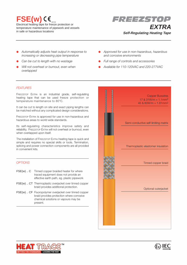
FREEZSTOP EXTRA is an industrial grade, self-regulatingheating tape that can be used freeze protection ortemperature maintenance to 80°C.
It can be cut to length on site and exact piping lengths canbe matched without any complicated design considerations.
FREEZSTOP EXTRA is approved for use in non-hazardous andhazardous areas to world wide standards.
Its self-regulating characteristics improve safety andreliability. FREEZSTOP EXTRA will not overheat or burnout, evenwhen overlapped upon itself.
The installation of FREEZSTOP EXTRA heating tape is quick andsimple and requires no special skills or tools. Termination,splicing and power connection components are all providedin convenient kits.
OPTIONS
FSE(w) .. C Tinned copper braided heater for wheretraced equipment does not provide aneffective earth path, eg. plastic pipework
FSE(w) .. CT Thermoplastic overjacket over tinned copperbraid provides additional protection.
FSE(w) .. CF Fluoropolymer overjacket over tinned copperbraid provides protection where corrosivechemical solutions or vapours may bepresent.
FREEZSTOPEXTRA
Self-Regulating Heating Tape
FSE(w)Electrical heating tape for freeze protection ortemperature maintenance of pipework and vesselsin safe or hazardous locations
Copper Buswires17 & 31W/m = 1.1mm2
45 & 60W/m = 1.81mm2
Semi-conductive self-limiting matrix
Thermoplastic elastomer insulation
Tinned copper braid
Optional outerjacket
0518
MAXIMUM TEMPERATURE 80°C (176°F)
MAX. PERMISSIBLE TEMPERATURE 100°C (212°F)de-energised (1000 hrs cumulative)
MINIMUM INSTALLATION –40°C (–40°F)TEMPERATURE (CENELEC –20°C, –4°F)
POWER SUPPLY 110 - 120 VAC, 220 - 277 VAC
TEMPERATURE T4 (135°C)CLASSIFIATION
MAXIMUM RESISTANCEOF PROTECTIVE BRAIDING 18.2 Ohm/km
WEIGHTS & DIMENSIONS
Type Nominal Weight Minimum GlandRef Dimensions kg/100m Bending Size
(mm) radiusFSE 10.9 x 3.8 5.8 20mm M20
FSE .. C 11.8 x 4.7 11.2 25mm M20
FSE .. C* 13.1 x 6.0 13.2 30mm M20
FSEw 12.5 x 3.9 11.5 20mm M20
FSEw .. C 13.5 x 5.0 18.4 25mm M20
FSEw .. C* 15.0 x 6.5 18.9 30mm M25
* Denotes (T)hermoplastic, or (F)luoropolymer outerjacket
APPROVAL DETAILS
Testing Authority Certificate No. Standard
ATEX Sira 02ATEX3076 EN50014 & EN50019
IEC Sira 02Y3066 CEI IEC62086
Lloyds Register 02/00062 EN50014, EN50019,BS6351, IEEE Std 515
Further approvals are available on request.
ORDERING INFORMATION
Example 45FSEw2-CF
Output 45W/m at 10°CFREEZSTOP EXTRA
Wide version (45 and 60W/m only)Supply Voltage 220 - 277V ACTinned Copper BraidFluoropolymer Outerjacket
ACCESSORIES
Heat Trace supply a complete range of accessories includingtermination/splice kits, end seals, junction boxes and controls.Such items carry separate approvals from the heating tapes.
SPECIFICATION
Tracer House, Cromwell Road, Bredbury, Stockport, Cheshire, SK6 2RF, UKTel: +44(0)161-430 8333 Fax: +44(0)161-430 8654 http://www.heat-trace.com
The information given herein, including drawings, illustrations and schematics (which are intended for illustration purposes only), is believed to be reliable. However, Heat Trace Ltd makes nowarranties as to its accuracy or completeness and disclaims any liability in connection with its use. Users of Heat Trace Ltd products should make their own evaluation to determine the suitabilityof each such product for specific applications. In no way will Heat Trace Ltd be liable for any damages arising out of the misuse, resale or use of the product.
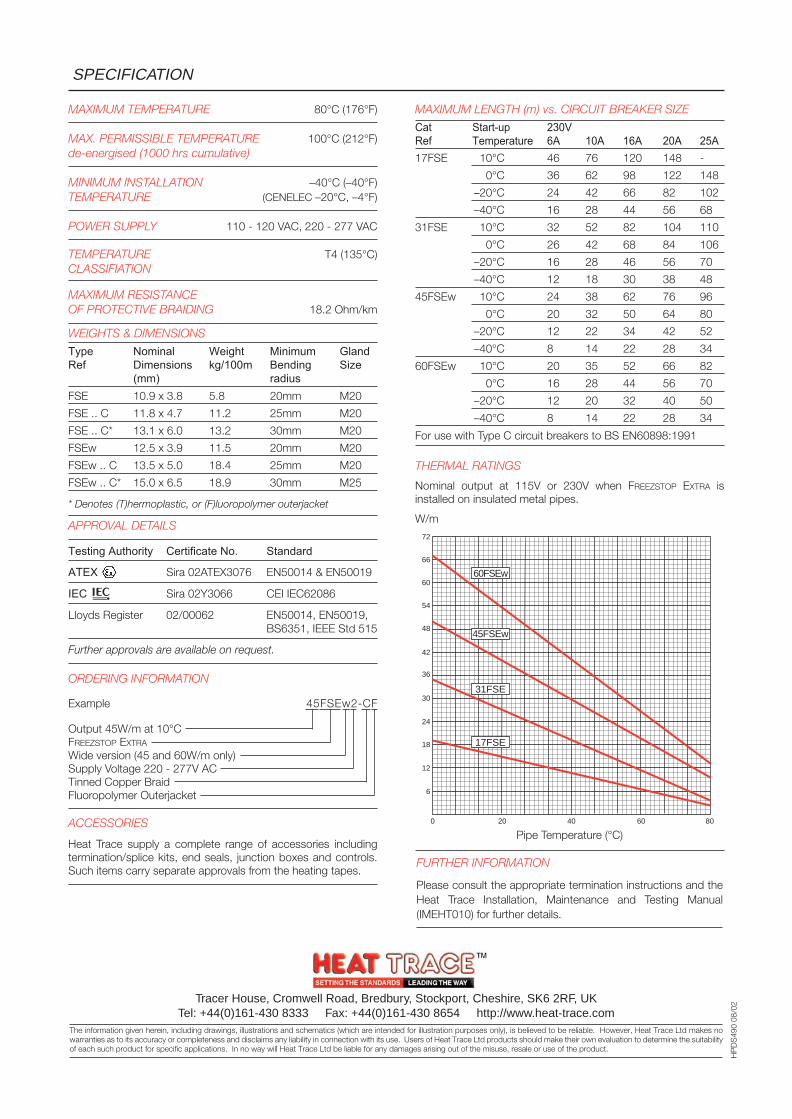
MAXIMUM LENGTH (m) vs. CIRCUIT BREAKER SIZE
Cat Start-up 230VRef Temperature 6A 10A 16A 20A 25A17FSE 10°C 46 76 120 148 -
0°C 36 62 98 122 148
–20°C 24 42 66 82 102
–40°C 16 28 44 56 68
31FSE 10°C 32 52 82 104 110
0°C 26 42 68 84 106
–20°C 16 28 46 56 70
–40°C 12 18 30 38 48
45FSEw 10°C 24 38 62 76 96
0°C 20 32 50 64 80
–20°C 12 22 34 42 52
–40°C 8 14 22 28 34
60FSEw 10°C 20 35 52 66 82
0°C 16 28 44 56 70
–20°C 12 20 32 40 50
–40°C 8 14 22 28 34
For use with Type C circuit breakers to BS EN60898:1991
THERMAL RATINGS
Nominal output at 115V or 230V when FREEZSTOP EXTRA isinstalled on insulated metal pipes.
W/m
HP
DS
490
08/0
2
0
6
12
18
24
30
36
42
54
60
66
72
48
20 40 60 80
45FSEw
60FSEw
31FSE
17FSE
Pipe Temperature (°C)
FURTHER INFORMATION
Please consult the appropriate termination instructions and theHeat Trace Installation, Maintenance and Testing Manual(IMEHT010) for further details.
Automatically adjusts heat output in response toincreasing or decreasing pipe temperature
Can be cut to length with no wastage
Will not overheat or burnout, even whenoverlapped
Approved for use in non-hazardous, hazardousand corrosive environments
Full range of controls and accessories
Available for 110 - 120 and 220 - 277VAC
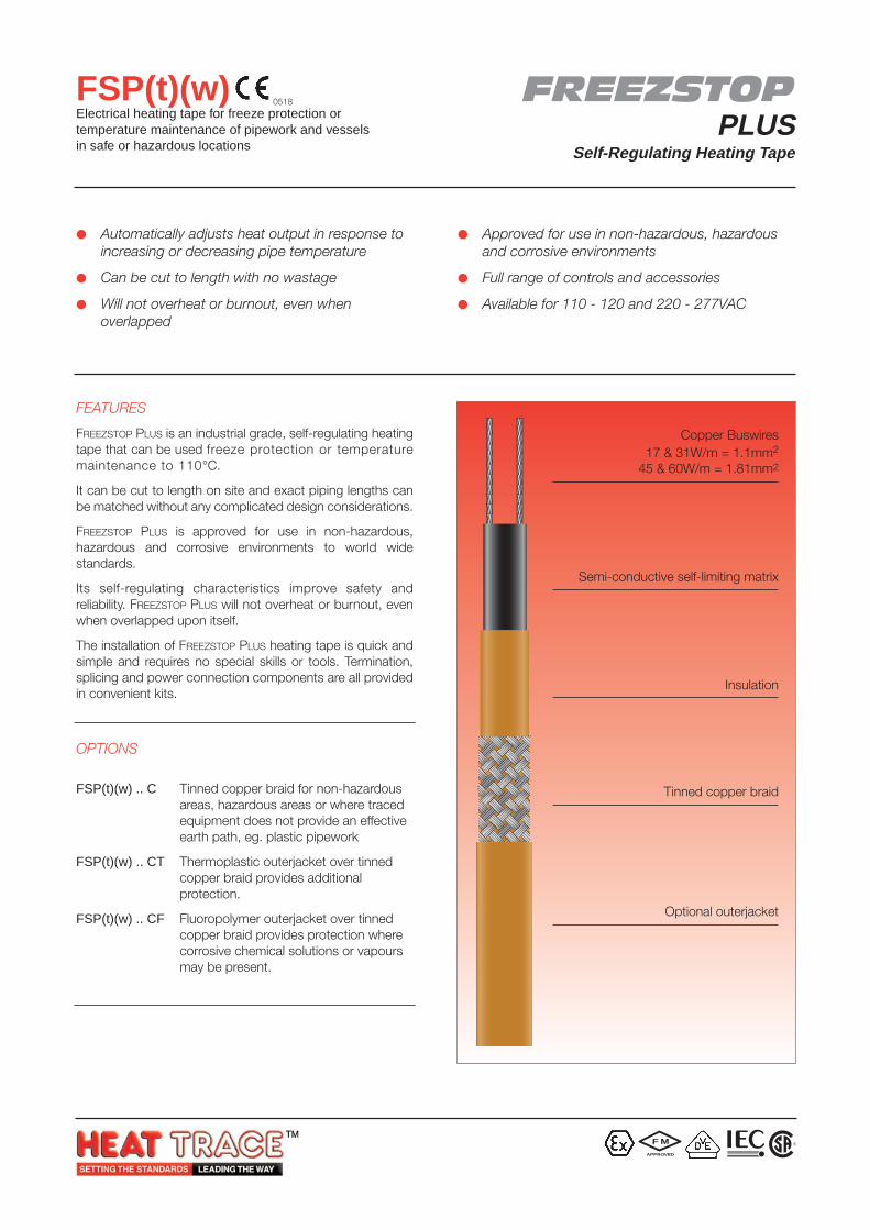
FEATURES
FREEZSTOP PLUS is an industrial grade, self-regulating heatingtape that can be used freeze protection or temperaturemaintenance to 110°C.
It can be cut to length on site and exact piping lengths canbe matched without any complicated design considerations.
FREEZSTOP PLUS is approved for use in non-hazardous,hazardous and corrosive environments to world widestandards.
Its self-regulating characteristics improve safety andreliability. FREEZSTOP PLUS will not overheat or burnout, evenwhen overlapped upon itself.
The installation of FREEZSTOP PLUS heating tape is quick andsimple and requires no special skills or tools. Termination,splicing and power connection components are all providedin convenient kits.
OPTIONS
FSP(t)(w) .. C Tinned copper braid for non-hazardousareas, hazardous areas or where tracedequipment does not provide an effectiveearth path, eg. plastic pipework
FSP(t)(w) .. CT Thermoplastic outerjacket over tinnedcopper braid provides additionalprotection.
FSP(t)(w) .. CF Fluoropolymer outerjacket over tinnedcopper braid provides protection wherecorrosive chemical solutions or vapoursmay be present.
FREEZSTOPPLUS
Self-Regulating Heating Tape
FSP(t)(w)Electrical heating tape for freeze protection ortemperature maintenance of pipework and vesselsin safe or hazardous locations
Copper Buswires17 & 31W/m = 1.1mm2
45 & 60W/m = 1.81mm2
Semi-conductive self-limiting matrix
Insulation
Tinned copper braid
Optional outerjacket
F M
APPROVED
0518
R
MAXIMUM TEMPERATURE 110°C (230°F)
MAX. PERMISSIBLE TEMPERATURE 135°C (275°F)de-energised (1000 hrs cumulative)
MINIMUM INSTALLATION –30°C (–22°F)TEMPERATURE (CENELEC –20°C, –4°F)
TEMPERATURE up to 45W/m T4 (135°C)CLASSIFICATION 60W/m T3 (200°C)
POWER SUPPLY 110 – 120VAC, 220 – 277VAC
MAXIMUM RESISTANCEOF PROTECTIVE BRAIDING 18.2 Ohm/km
WEIGHTS & DIMENSIONS
Type Nom. Dims. Weight Min. Bending GlandRef (mm) kg/100m radius SizeFSP(t) 9.9 x 3.3 7.1 20mm M20
FSP(t) .. C 10.8 x 4.1 10.4 25mm M20
FSP(t) .. C* 12.0 x 5.3 13.9 30mm M20
FSP(t)w 12.4 x 3.4 9.7 20mm M20
FSP(t)w .. C 13.3 x 4.3 16.6 25mm M20
FSP(t)w .. C* 14.6 x 5.6 17.1 30mm M25
* Denotes (T)hermoplastic, or (F)luoropolymer outerjacket
APPROVAL DETAILS
Testing Authority Certificate No. Standard
CENELEC SCS Ex 94D3079 EN50014 & EN50019
ATEX Sira 02ATEX3071 EN50014, EN50019 &IEC62086
IEC Sira 02Y3061 CEI IEC62086 &IEC60079-7
FM J.I.3YA0.AX (3770) ANSI/IEEE Std 515
VDE 114665 DIN VDE 0254
CSA 214197-1295278 C22.2 No. 130.1C22.2 No. 130.2C22.2 No. 138
Lloyds Register 02/00062 EN50014, EN50019,BS6351, IEEE Std 515
Further approvals are available on request.
ORDERING INFORMATION
Example 45FSPtw2-CF
Output 45W/m at 10°CFREEZSTOP PLUS
Insulation jacket* (optionally Thermoplastic)Wide version (45 and 60W/m only)Supply Voltage 220 - 277V ACTinned Copper BraidFluoropolymer Outer jacket
ACCESSORIESHeat Trace supply a complete range of accessories includingtermination/splice kits, end seals, junction boxes and controls.Such items carry separate approvals from the heating tapes.When used in hazardous areas, only use approved components.
* Standard insulation material is fluoropolymer
SPECIFICATION
Tracer House, Cromwell Road, Bredbury, Stockport, Cheshire, SK6 2RF, UKTel: +44(0)161-430 8333 Fax: +44(0)161-430 8654 http://www.heat-trace.com
The information given herein, including drawings, illustrations and schematics (which are intended for illustration purposes only), is believed to be reliable. However, Heat Trace Ltd makes nowarranties as to its accuracy or completeness and disclaims any liability in connection with its use. Users of Heat Trace Ltd products should make their own evaluation to determine the suitabilityof each such product for specific applications. In no way will Heat Trace Ltd be liable for any damages arising out of the misuse, resale or use of the product.
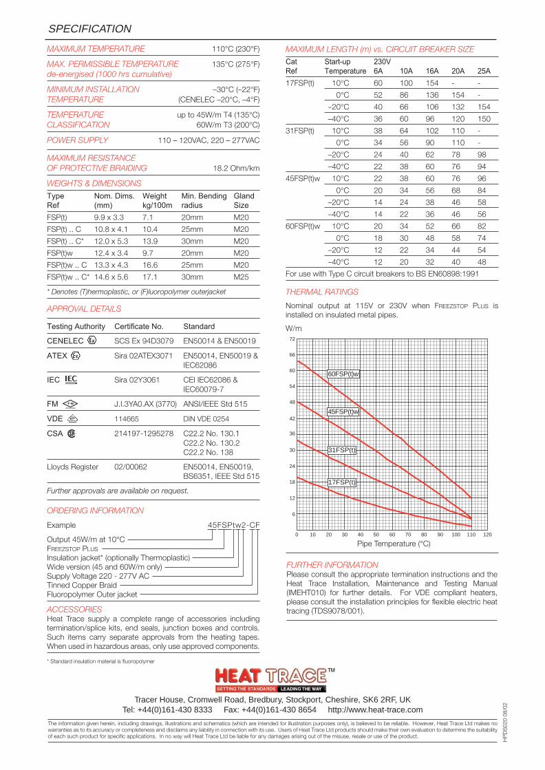
MAXIMUM LENGTH (m) vs. CIRCUIT BREAKER SIZE
Cat Start-up 230VRef Temperature 6A 10A 16A 20A 25A17FSP(t) 10°C 60 100 154 - -
0°C 52 86 136 154 -
–20°C 40 66 106 132 154
–40°C 36 60 96 120 150
31FSP(t) 10°C 38 64 102 110 -
0°C 34 56 90 110 -
–20°C 24 40 62 78 98
–40°C 22 38 60 76 94
45FSP(t)w 10°C 22 38 60 76 96
0°C 20 34 56 68 84
–20°C 14 24 38 46 58
–40°C 14 22 36 46 56
60FSP(t)w 10°C 20 34 52 66 82
0°C 18 30 48 58 74
–20°C 12 22 34 44 54
–40°C 12 20 32 40 48
For use with Type C circuit breakers to BS EN60898:1991
THERMAL RATINGS
Nominal output at 115V or 230V when FREEZSTOP PLUS isinstalled on insulated metal pipes.
W/m
HP
DS
020
08/0
2
0 10
6
12
18
24
30
36
42
54
60
66
72
48
20 30 40 50 60 70 80 90 120100 110
60FSP(t)w
45FSP(t)w
31FSP(t)
17FSP(t)
Pipe Temperature (°C)
FURTHER INFORMATIONPlease consult the appropriate termination instructions and theHeat Trace Installation, Maintenance and Testing Manual(IMEHT010) for further details. For VDE compliant heaters,please consult the installation principles for flexible electric heattracing (TDS9078/001).
F M
APPROVED
R
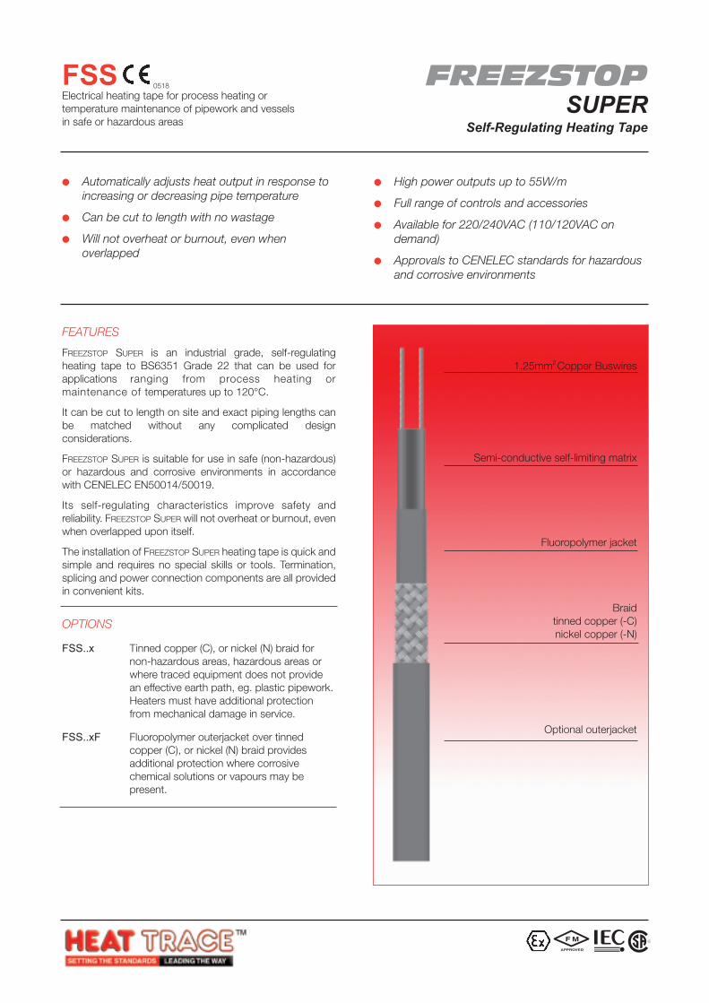
FEATURES
FREEZSTOP SUPER is an industrial grade, self-regulatingheating tape to BS6351 Grade 22 that can be used forapplications ranging from process heating ormaintenance of temperatures up to 120°C.
It can be cut to length on site and exact piping lengths canbe matched without any complicated designconsiderations.
FREEZSTOP SUPER is suitable for use in safe (non-hazardous)or hazardous and corrosive environments in accordancewith CENELEC EN50014/50019.
Its self-regulating characteristics improve safety andreliability. FREEZSTOP SUPER will not overheat or burnout, evenwhen overlapped upon itself.
The installation of FREEZSTOP SUPER heating tape is quick andsimple and requires no special skills or tools. Termination,splicing and power connection components are all providedin convenient kits.
OPTIONS
FSS..x Tinned copper (C), or nickel (N) braid fornon-hazardous areas, hazardous areas orwhere traced equipment does not providean effective earth path, eg. plastic pipework.Heaters must have additional protectionfrom mechanical damage in service.
FSS..xF Fluoropolymer outerjacket over tinnedcopper (C), or nickel (N) braid providesadditional protection where corrosivechemical solutions or vapours may bepresent.
Automatically adjusts heat output in response toincreasing or decreasing pipe temperature
Can be cut to length with no wastage
Will not overheat or burnout, even whenoverlapped
High power outputs up to 55W/m
Full range of controls and accessories
Available for 220/240VAC (110/120VAC ondemand)
Approvals to CENELEC standards for hazardousand corrosive environments
FREEZSTOPSUPER
Self-Regulating Heating Tape
FSSElectrical heating tape for process heating ortemperature maintenance of pipework and vesselsin safe or hazardous areas
1.25mm2 Copper Buswires
Semi-conductive self-limiting matrix
Fluoropolymer jacket
Braidtinned copper (-C)nickel copper (-N)
Optional outerjacket
0518
F M
APPROVED
R
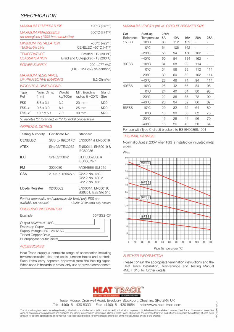
MAXIMUM TEMPERATURE 120°C (248°F)
MAXIMUM PERMISSIBLE 200°C (374°F)de-energised (1000 hrs cumulative)
MINIMUM INSTALLATION –30°C (–22°F)TEMPERATURE CENELEC –20°C (–4°F)
TEMPERATURE Braided - T2 (300°C)CLASSIFICATION Braid and Outerjacket - T3 (200°C)
POWER SUPPLY 220 - 277 VAC(110 - 120 VAC on demand)
MAXIMUM RESISTANCEOF PROTECTIVE BRAIDING 18.2 Ohm/km
WEIGHTS & DIMENSIONS
Type Nom. Dims. Weight Min. Bending GlandRef (mm) kg/100m radius @ –20°C Size
FSS 8.6 x 3.1 3.2 20 mm M20
FSS..x 9.5 x 3.9 6.1 25 mm M20
FSS..xF 10.7 x 5.1 7.9 30 mm M20
‘x’ denotes ‘C’ for tinned, or ‘N’ for nickel copper braid
APPROVAL DETAILS
Testing Authority Certificate No. Standard
CENELEC SCS Ex 99E3175* EN50014 & EN50019
ATEX Sira 02ATEX3072 EN50014, EN50019 &IEC62086
IEC Sira 02Y3062 CEI IEC62086 &IEC60079-7
FM 3009080 ANSI/IEEE Std 515
CSA 214197-1295278 C22.2 No. 130.1C22.2 No. 130.2C22.2 No. 138
Lloyds Register 02/00062 EN50014, EN50019,BS6351, IEEE Std 515
Further approvals, and approvals for braid only FSS are available on request. * Suffix ‘X’ for braid only heaters
ORDERING INFORMATION
Example 55FSS2-CF
Output 55W/m at 10°CFreezstop SuperSupply Voltage 220 - 240V ACTinned Copper BraidFluoropolymer outer jacket
ACCESSORIES
Heat Trace supply a complete range of accessories includingtermination/splice kits, end seals, junction boxes and controls.Such items carry separate approvals from the heating tapes.When used in hazardous areas, only use approved components.
SPECIFICATION
MAXIMUM LENGTH (m) vs. CIRCUIT BREAKER SIZE
Cat Start-up 230VReference Temperature 6A 10A 16A 20A 25A15FSS 10°C 68 112 162 - -
0°C 64 106 162 - -
–20°C 56 94 150 162 -
–40°C 50 84 134 162 -
30FSS 10°C 34 58 92 114 -
0°C 34 56 88 112 114
–20°C 30 50 82 102 114
–40°C 28 46 74 94 114
40FSS 10°C 26 42 66 84 98
0°C 24 40 64 80 98
–20°C 22 36 58 72 90
–40°C 20 34 52 66 82
55FSS 10°C 20 32 52 64 80
0°C 18 30 50 62 78
–20°C 16 28 44 56 70
–40°C 16 26 40 50 64
For use with Type C circuit breakers to BS EN60898:1991
THERMAL RATINGS
Nominal output at 230V when FSS is installed on insulated metalpipes.
W/m
0 10
5
10
15
20
25
30
35
45
50
55
60
40
20 30 40 50 60 70 80 90 120100 110
30FSS
15FSS
40FSS
55FSS
HP
DS
290
05/0
3
Pipe Temperature (oC)
FURTHER INFORMATION
Please consult the appropriate termination instructions and theHeat Trace Installation, Maintenance and Testing Manual(IMEHT010) for further details.
Tracer House, Cromwell Road, Bredbury, Stockport, Cheshire, SK6 2RF, UKTel: +44(0)161-430 8333 Fax: +44(0)161-430 8654 http://www.heat-trace.com
The information given herein, including drawings, illustrations and schematics (which are intended for illustration purposes only), is believed to be reliable. However, Heat Trace Ltd makes no warrantiesas to its accuracy or completeness and disclaims any liability in connection with its use. Users of Heat Trace Ltd products should make their own evaluation to determine the suitability of each suchproduct for specific applications. In no way will Heat Trace Ltd be liable for any damages arising out of the misuse, resale or use of the product.
FEATURES
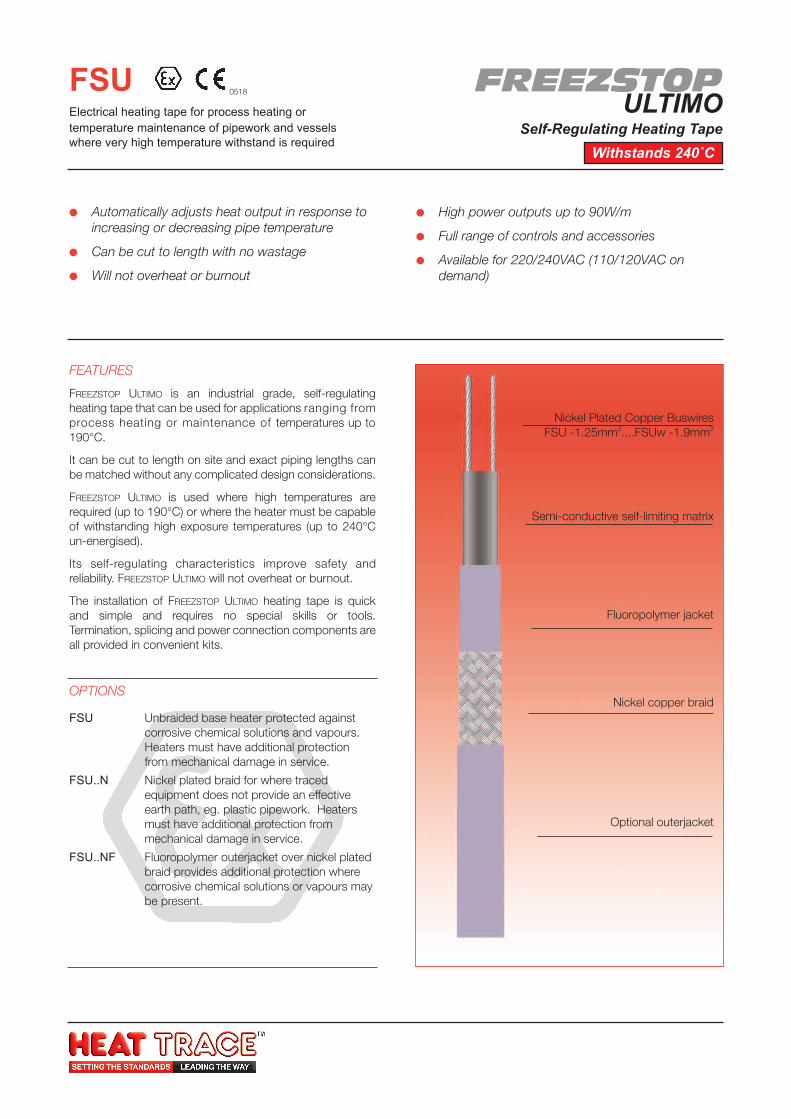
FREEZSTOP ULTIMO is an industrial grade, self-regulatingheating tape that can be used for applications ranging fromprocess heating or maintenance of temperatures up to190°C.
It can be cut to length on site and exact piping lengths canbe matched without any complicated design considerations.
FREEZSTOP ULTIMO is used where high temperatures arerequired (up to 190°C) or where the heater must be capableof withstanding high exposure temperatures (up to 240°Cun-energised).
Its self-regulating characteristics improve safety andreliability. FREEZSTOP ULTIMO will not overheat or burnout.
The installation of FREEZSTOP ULTIMO heating tape is quickand simple and requires no special skills or tools.Termination, splicing and power connection components areall provided in convenient kits.
OPTIONS
FSU Unbraided base heater protected againstcorrosive chemical solutions and vapours.Heaters must have additional protectionfrom mechanical damage in service.
FSU..N Nickel plated braid for where tracedequipment does not provide an effectiveearth path, eg. plastic pipework. Heatersmust have additional protection frommechanical damage in service.
FSU..NF Fluoropolymer outerjacket over nickel platedbraid provides additional protection wherecorrosive chemical solutions or vapours maybe present.
Automatically adjusts heat output in response toincreasing or decreasing pipe temperature
Can be cut to length with no wastage
Will not overheat or burnout
High power outputs up to 90W/m
Full range of controls and accessories
Available for 220/240VAC (110/120VAC ondemand)
FSUElectrical heating tape for process heating ortemperature maintenance of pipework and vesselswhere very high temperature withstand is required
Nickel Plated Copper BuswiresFSU -1.25mm2....FSUw -1.9mm2
Semi-conductive self-limiting matrix
Fluoropolymer jacket
Nickel copper braid
Optional outerjacket
0518 FREEZSTOPULTIMO
Self-Regulating Heating Tape
Withstands 240˚C1
Tracer House, Cromwell Road, Bredbury, Stockport, Cheshire, SK6 2RF, UKTel: +44(0)161-430 8333 Fax: +44(0)161-430 8654 http://www.heat-trace.com
The information given herein, including drawings, illustrations and schematics (which are intended for illustration purposes only), is believed to be reliable. However, Heat Trace Ltd makes no warrantiesas to its accuracy or completeness and disclaims any liability in connection with its use. Users of Heat Trace Ltd products should make their own evaluation to determine the suitability of each suchproduct for specific applications. In no way will Heat Trace Ltd be liable for any damages arising out of the misuse, resale or use of the product.
HP
DS
410
10/0
3
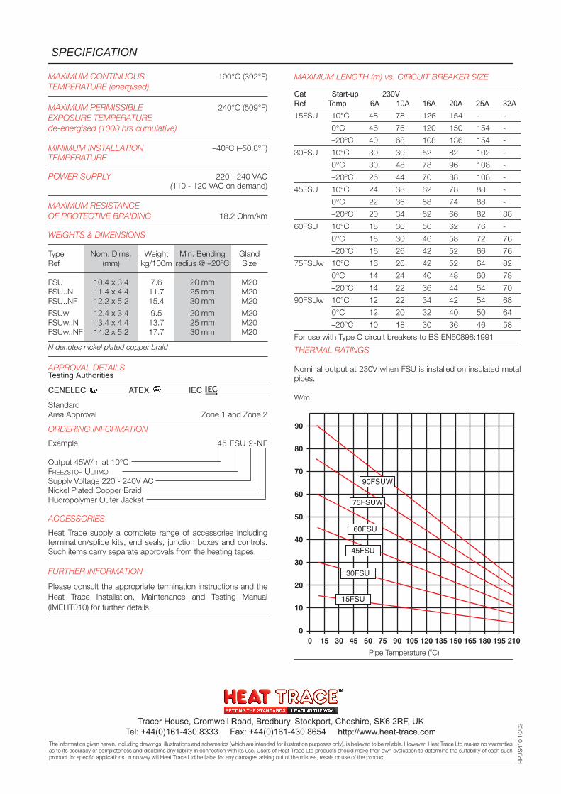
MAXIMUM CONTINUOUS 190°C (392°F)TEMPERATURE (energised)
MAXIMUM PERMISSIBLE 240°C (509°F)EXPOSURE TEMPERATUREde-energised (1000 hrs cumulative)
MINIMUM INSTALLATION –40°C (–50.8°F)TEMPERATURE
POWER SUPPLY 220 - 240 VAC(110 - 120 VAC on demand)
MAXIMUM RESISTANCEOF PROTECTIVE BRAIDING 18.2 Ohm/km
WEIGHTS & DIMENSIONS
Type Nom. Dims. Weight Min. Bending GlandRef (mm) kg/100m radius @ –20°C Size
FSU 10.4 x 3.4 7.6 20 mm M20FSU..N 11.4 x 4.4 11.7 25 mm M20FSU..NF 12.2 x 5.2 15.4 30 mm M20
FSUw 12.4 x 3.4 9.5 20 mm M20FSUw..N 13.4 x 4.4 13.7 25 mm M20FSUw..NF 14.2 x 5.2 17.7 30 mm M20
N denotes nickel plated copper braid
APPROVAL DETAILSTesting Authorities
CENELEC ATEX IEC
StandardArea Approval Zone 1 and Zone 2
ORDERING INFORMATION
Example 45 FSU 2-NF
Output 45W/m at 10°CFREEZSTOP ULTIMO
Supply Voltage 220 - 240V ACNickel Plated Copper BraidFluoropolymer Outer Jacket
ACCESSORIES
Heat Trace supply a complete range of accessories includingtermination/splice kits, end seals, junction boxes and controls.Such items carry separate approvals from the heating tapes.
FURTHER INFORMATION
Please consult the appropriate termination instructions and theHeat Trace Installation, Maintenance and Testing Manual(IMEHT010) for further details.
SPECIFICATION
Pipe Temperature (oC)
MAXIMUM LENGTH (m) vs. CIRCUIT BREAKER SIZE
Cat Start-up 230VRef Temp 6A 10A 16A 20A 25A 32A15FSU 10°C 48 78 126 154 - -
0°C 46 76 120 150 154 -
–20°C 40 68 108 136 154 -
30FSU 10°C 30 30 52 82 102 -
0°C 30 48 78 96 108 -
–20°C 26 44 70 88 108 -
45FSU 10°C 24 38 62 78 88 -
0°C 22 36 58 74 88 -
–20°C 20 34 52 66 82 88
60FSU 10°C 18 30 50 62 76 -
0°C 18 30 46 58 72 76
–20°C 16 26 42 52 66 76
75FSUw 10°C 16 26 42 52 64 82
0°C 14 24 40 48 60 78
–20°C 14 22 36 44 54 70
90FSUw 10°C 12 22 34 42 54 68
0°C 12 20 32 40 50 64
–20°C 10 18 30 36 46 58
For use with Type C circuit breakers to BS EN60898:1991
THERMAL RATINGS
Nominal output at 230V when FSU is installed on insulated metalpipes.
W/m
0 15 30 45 60 75 90 105 120 135 150 165 180 195 210
90
80
70
60
50
40
30
20
10
0
90FSUW
75FSUW
60FSU
45FSU
30FSU
15FSU
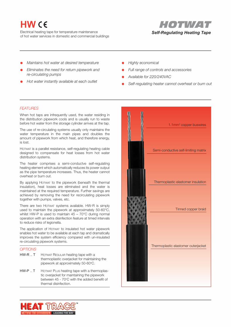
HOTWATSelf-Regulating Heating Tape
HWElectrical heating tape for temperature maintenanceof hot water services in domestic and commercial buildings
FEATURES
When hot taps are infrequently used, the water residing inthe distribution pipework cools and is usually run to wastebefore hot water from the storage cylinder arrives at the tap.
The use of re-circulating systems usually only maintains thewater temperature in the main pipes and doubles theamount of pipework from which heat, and therefore energy,is lost.
HOTWAT is a parallel resistance, self-regulating heating cabledesigned to compensate for heat losses from hot waterdistribution systems.
The heater comprises a semi-conductve self-regulatingheating element which automatically reduces its power outputas the pipe temperature increases. Thus, the heater cannotoverheat or burn out.
By applying HOTWAT to the pipework (beneath the thermalinsulation), heat losses are eliminated and the water ismaintained at the required temperature. Further savings areachieved by removing the need for recirculating pipeworktogether with pumps, valves, etc.
There are two HOTWAT systems available. HW-R is simplyused to maintain the pipework at approximately 50-60°C,whilst HW-P is used to maintain 45 – 70°C during normaloperation with an extra disinfection feature at timed intervalsto reduce risks of legionella.
The application of HOTWAT to insulated hot water pipeworkenables hot water to be available at each tap and dramaticallyimproves the system efficiency compared with un-insulatedre-circulating pipework systems.
OPTIONSHW-R .. T HOTWAT REGULAR heating tape with a
thermoplastic overjacket for maintaining thepipework at approximately 50-60oC.
HW-P .. T HOTWAT PLUS heating tape with a thermoplas-tic overjacket for maintaining the pipeworkbetween 45 - 70oC with the added benefit ofthermal disinfection.
Maintains hot water at desired temperature
Eliminates the need for return pipework andre-circulating pumps
Hot water instantly available at each outlet
Highly economical
Full range of controls and accessories
Available for 220/240VAC
Self-regulating heater cannot overheat or burn out
1.1mm2 copper buswires
Semi-conductive self-limiting matrix
Thermoplastic elastomer insulation
Tinned copper braid
Thermoplastic elastomer outerjacket
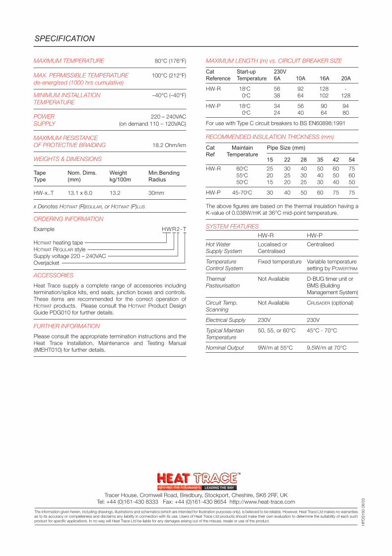
MAXIMUM TEMPERATURE 80°C (176°F)
MAX. PERMISSIBLE TEMPERATURE 100°C (212°F)de-energised (1000 hrs cumulative)
MINIMUM INSTALLATION –40°C (–40°F)TEMPERATURE
POWER 220 – 240VACSUPPLY (on demand 110 – 120VAC)
MAXIMUM RESISTANCEOF PROTECTIVE BRAIDING 18.2 Ohm/km
WEIGHTS & DIMENSIONS
Tape Nom. Dims. Weight Min.BendingType (mm) kg/100m Radius
HW-x..T 13.1 x 6.0 13.2 30mm
x Denotes HOTWAT (R)EGULAR, or HOTWAT (P)LUS
ORDERING INFORMATION
Example HWR2-T
HOTWAT heating tapeHOTWAT REGULAR styleSupply voltage 220 – 240VACOverjacket
ACCESSORIES
Heat Trace supply a complete range of accessories includingtermination/splice kits, end seals, junction boxes and controls.These items are recommended for the correct operation ofHOTWAT products. Please consult the HOTWAT Product DesignGuide PDG010 for further details.
FURTHER INFORMATION
Please consult the appropriate termination instructions and theHeat Trace Installation, Maintenance and Testing Manual(IMEHT010) for further details.
MAXIMUM LENGTH (m) vs. CIRCUIT BREAKER SIZE
Cat Start-up 230VReference Temperature 6A 10A 16A 20A
HW-R 18oC 56 92 128 -0oC 38 64 102 128
HW-P 18oC 34 56 90 940oC 24 40 64 80
For use with Type C circuit breakers to BS EN60898:1991
RECOMMENDED INSULATION THICKNESS (mm)
Cat Maintain Pipe Size (mm)Ref Temperature
15 22 28 35 42 54HW-R 60oC 25 30 40 50 60 75
55oC 20 25 30 40 50 6050oC 15 20 25 30 40 50
HW-P 45-70oC 30 40 50 60 75 75
The above figures are based on the thermal insulation having aK-value of 0.038W/mK at 36°C mid-point temperature.
SYSTEM FEATURES
HW-R HW-PHot Water Localised or CentralisedSupply System Centralised
Temperature Fixed temperature Variable temperatureControl System setting by POWERTRIM
Thermal Not Available D-BUG timer unit orPasteurisation BMS (Building
Management System)
Circuit Temp. Not Available CRUSADER (optional)Scanning
Electrical Supply 230V 230V
Typical Maintain 50, 55, or 60°C 45°C - 70°CTemperature
Nominal Output 9W/m at 55°C 9.5W/m at 70°C
SPECIFICATION
Tracer House, Cromwell Road, Bredbury, Stockport, Cheshire, SK6 2RF, UKTel: +44 (0)161-430 8333 Fax: +44 (0)161-430 8654 http://www.heat-trace.com
The information given herein, including drawings, illustrations and schematics (which are intended for illustration purposes only), is believed to be reliable. However, Heat Trace Ltd makes no warrantiesas to its accuracy or completeness and disclaims any liability in connection with its use. Users of Heat Trace Ltd products should make their own evaluation to determine the suitability of each suchproduct for specific applications. In no way will Heat Trace Ltd be liable for any damages arising out of the misuse, resale or use of the product.
HP
DS
160
08/0
3
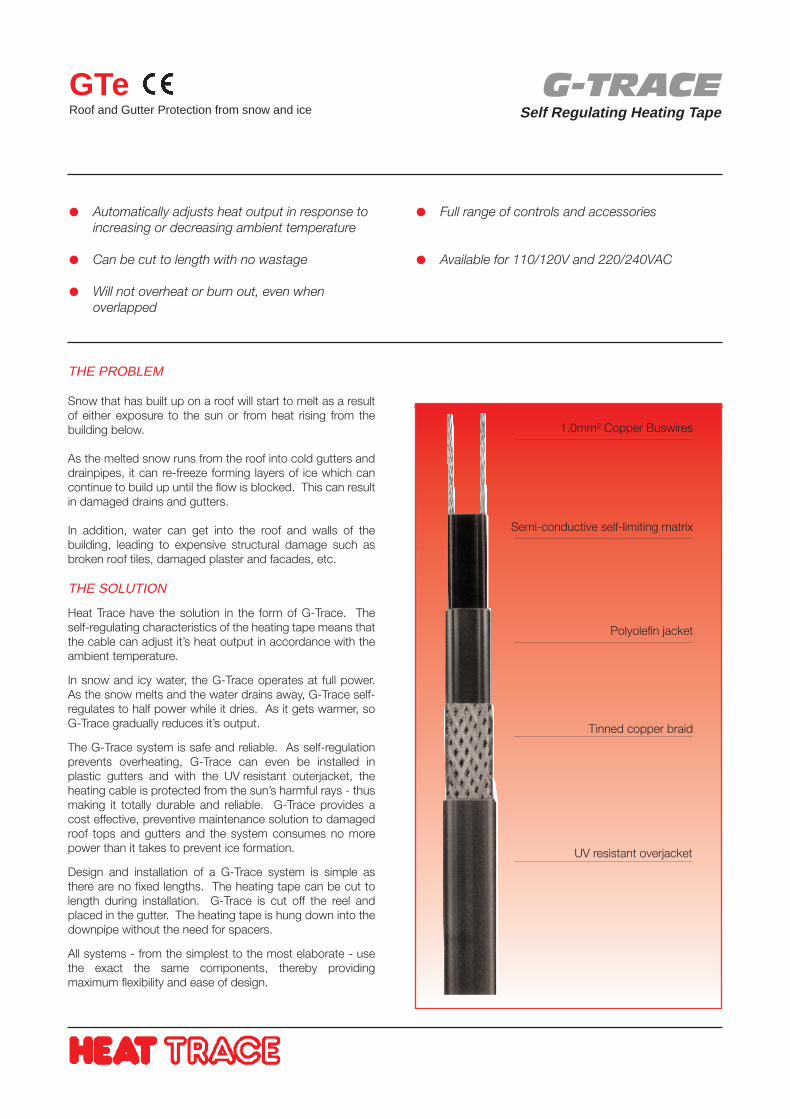
G-TRACESelf Regulating Heating Tape
GTeRoof and Gutter Protection from snow and ice
THE PROBLEM
Snow that has built up on a roof will start to melt as a resultof either exposure to the sun or from heat rising from thebuilding below.
As the melted snow runs from the roof into cold gutters anddrainpipes, it can re-freeze forming layers of ice which cancontinue to build up until the flow is blocked. This can resultin damaged drains and gutters.
In addition, water can get into the roof and walls of thebuilding, leading to expensive structural damage such asbroken roof tiles, damaged plaster and facades, etc.
THE SOLUTION
Heat Trace have the solution in the form of G-Trace. Theself-regulating characteristics of the heating tape means thatthe cable can adjust it’s heat output in accordance with theambient temperature.
In snow and icy water, the G-Trace operates at full power.As the snow melts and the water drains away, G-Trace self-regulates to half power while it dries. As it gets warmer, soG-Trace gradually reduces it’s output.
The G-Trace system is safe and reliable. As self-regulationprevents overheating, G-Trace can even be installed inplastic gutters and with the UV resistant outerjacket, theheating cable is protected from the sun’s harmful rays - thusmaking it totally durable and reliable. G-Trace provides acost effective, preventive maintenance solution to damagedroof tops and gutters and the system consumes no morepower than it takes to prevent ice formation.
Design and installation of a G-Trace system is simple asthere are no fixed lengths. The heating tape can be cut tolength during installation. G-Trace is cut off the reel andplaced in the gutter. The heating tape is hung down into thedownpipe without the need for spacers.
All systems - from the simplest to the most elaborate - usethe exact the same components, thereby providingmaximum flexibility and ease of design.
Automatically adjusts heat output in response toincreasing or decreasing ambient temperature
Can be cut to length with no wastage
Will not overheat or burn out, even whenoverlapped
Full range of controls and accessories
Available for 110/120V and 220/240VAC
1.0mm² Copper Buswires
Semi-conductive self-limiting matrix
Polyolefin jacket
Tinned copper braid
UV resistant overjacket
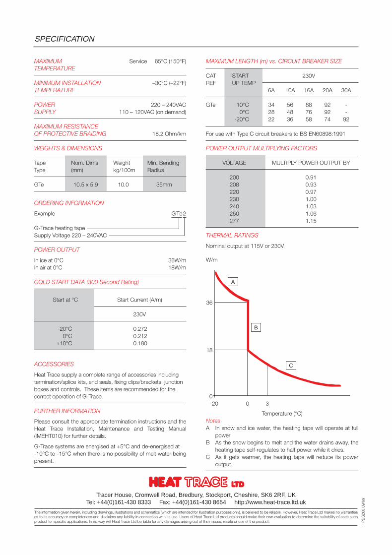
MAXIMUM LENGTH (m) vs. CIRCUIT BREAKER SIZE
CAT START 230VREF UP TEMP
6A 10A 16A 20A 30A
GTe 10°C 34 56 88 92 -0°C 28 48 76 92 -
-20°C 22 36 58 74 92
For use with Type C circuit breakers to BS EN60898:1991
POWER OUTPUT MULTIPLYING FACTORS
VOLTAGE MULTIPLY POWER OUTPUT BY
200 0.91208 0.93220 0.97230 1.00240 1.03250 1.06277 1.15
THERMAL RATINGS
Nominal output at 115V or 230V.
W/m
36
18
0-20 0 3
Temperature (°C)NotesA In snow and ice water, the heating tape will operate at full
powerB As the snow begins to melt and the water drains away, the
heating tape self-regulates to half power while it dries.C As it gets warmer, the heating tape will reduce its power
output.
MAXIMUM Service 65°C (150°F)TEMPERATURE
MINIMUM INSTALLATION –30°C (–22°F)TEMPERATURE
POWER 220 – 240VACSUPPLY 110 – 120VAC (on demand)
MAXIMUM RESISTANCEOF PROTECTIVE BRAIDING 18.2 Ohm/km
WEIGHTS & DIMENSIONS
Tape Nom. Dims. Weight Min. BendingType (mm) kg/100m Radius
GTe 10.5 x 5.9 10.0 35mm
ORDERING INFORMATION
Example GTe2
G-Trace heating tapeSupply Voltage 220 – 240VAC
POWER OUTPUT
In ice at 0°C 36W/mIn air at 0°C 18W/m
COLD START DATA (300 Second Rating)
Start at °C Start Current (A/m)
230V
-20°C 0.2720°C 0.212
+10°C 0.180
ACCESSORIES
Heat Trace supply a complete range of accessories includingtermination/splice kits, end seals, fixing clips/brackets, junctionboxes and controls. These items are recommended for thecorrect operation of G-Trace.
FURTHER INFORMATION
Please consult the appropriate termination instructions and theHeat Trace Installation, Maintenance and Testing Manual(IMEHT010) for further details.
G-Trace systems are energised at +5°C and de-energised at-10°C to -15°C when there is no possibility of melt water beingpresent.
SPECIFICATION
Tracer House, Cromwell Road, Bredbury, Stockport, Cheshire, SK6 2RF, UKTel: +44(0)161-430 8333 Fax: +44(0)161-430 8654 http://www.heat-trace.ltd.uk
The information given herein, including drawings, illustrations and schematics (which are intended for illustration purposes only), is believed to be reliable. However, Heat Trace Ltd makes no warrantiesas to its accuracy or completeness and disclaims any liability in connection with its use. Users of Heat Trace Ltd products should make their own evaluation to determine the suitability of each suchproduct for specific applications. In no way will Heat Trace Ltd be liable for any damages arising out of the misuse, resale or use of the product.
HP
DS
260
09/9
9
A
B
C
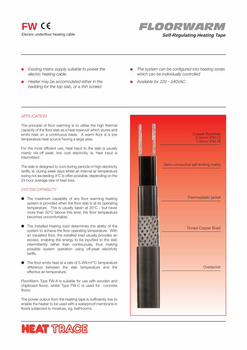
FLOORWARMSelf-Regulating Heating Tape
FWElectric underfloor heating cable
APPLICATION
The principle of floor warming is to utilise the high thermalcapacity of the floor slab as a heat reservoir which stores andemits heat on a continuous basis. A warm floor is a lowtemperature heat source having a large area.
For the most efficient use, heat input to the slab is usuallymainly via off peak, low cost electricity, ie. heat input isintermittent.
The slab is designed to cool during periods of high electricitytariffs, ie. during week days whilst an internal air temperatureswing not exceeding 3°C is often possible, depending on the24 hour average rate of heat loss.
SYSTEM CAPABILITY
The maximum capability of any floor warming heatingsystem is provided when the floor slab is at its operatingtemperature. This is usually taken at 25°C - but nevermore than 30°C (above this level, the floor temperaturebecomes uncomfortable).
The installed heating load determines the ability of thesystem to achieve the floor operating temperature. Withan insulated floor, the installed load usually provides anexcess, enabling the energy to be inputted to the slabintermittently rather than continuously, thus makingpossible system operation using off-peak electricitytariffs.
The floor emits heat at a rate of 5.4W/m²°C temperaturedifference between the slab temperature and theeffective air temperature.
FloorWarm Type FW-A is suitable for use with wooden andchipboard floors, whilst Type FW-C is used for concretefloors.
The power output from the heating tape is sufficiently low toenable the heater to be used with a waterproof membrane infloors subjected to moisture, eg. bathrooms.
Existing mains supply suitable to power theelectric heating cable.
Heater may be accomodated either in thebedding for the top slab, or a thin screed
The system can be configured into heating zoneswhich can be individually controlled
Available for 220 - 240VAC
Copper Buswires0.5mm² (FW-C)1.0mm² (FW-A)
Semi-conductive self-limiting matrix
Thermoplastic jacket
Tinned Copper Braid
Overjacket
Tracer House, Cromwell Road, Bredbury, Stockport, Cheshire, SK6 2RF, U.K.Tel: +44(0)161-430 8333 Fax: +44(0)161-430 8654 http://www.heat-trace.ltd.uk
The information given herein, including drawings, illustrations and schematics (which are intended for illustration purposes only), is believed to be reliable. However, Heat Trace Ltd makes no warrantiesas to its accuracy or completeness and disclaims any liability in connection with its use. Users of Heat Trace Ltd products should make their own evaluation to determine the suitability of each suchproduct for specific applications. In no way will Heat Trace Ltd be liable for any damages arising out of the misuse, resale or use of the product.
HP
DS
270
09/9
9
SPECIFICATION
Ideal Temperature Distribution Curve
Curve for Floor Heating
Curve for Radiator Heating
Room Temperature (°C)
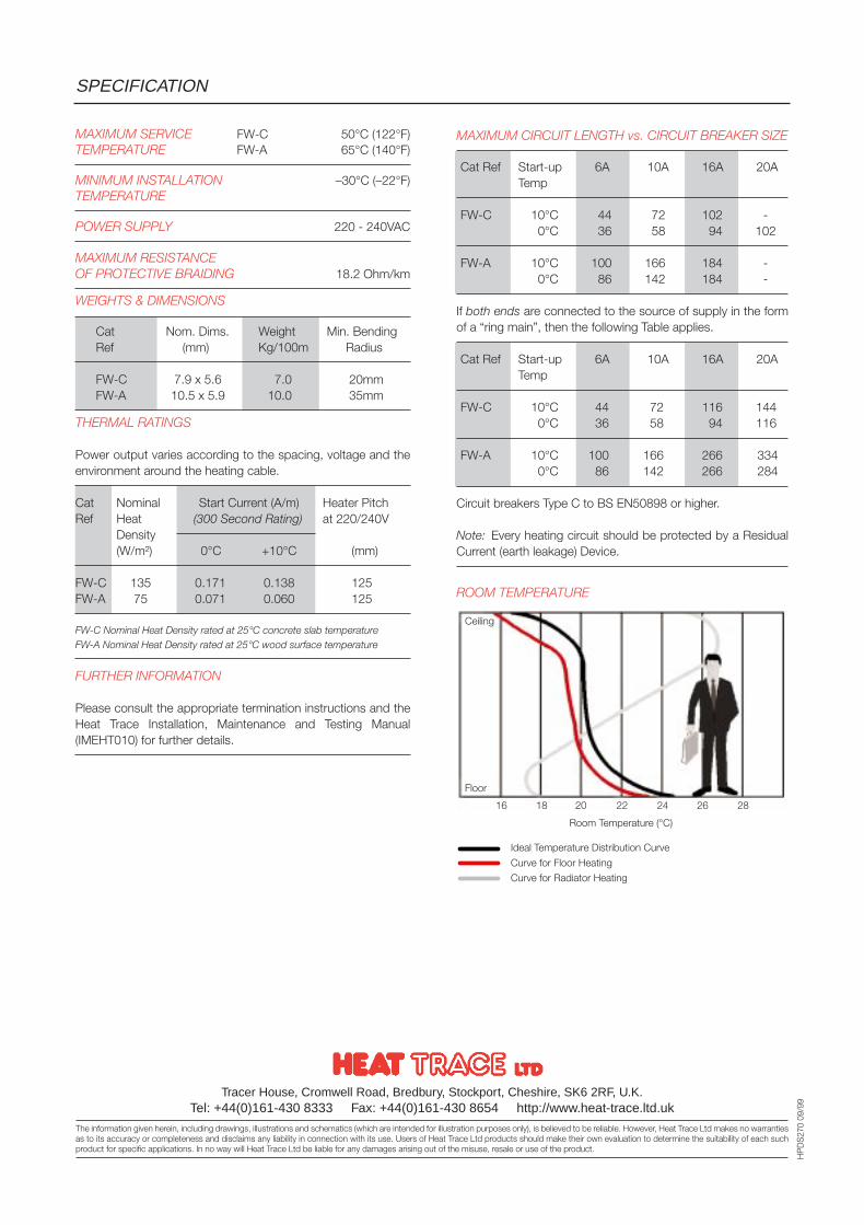
MAXIMUM CIRCUIT LENGTH vs. CIRCUIT BREAKER SIZE
Cat Ref Start-up 6A 10A 16A 20ATemp
FW-C 10°C 44 72 102 -0°C 36 58 94 102
FW-A 10°C 100 166 184 -0°C 86 142 184 -
If both ends are connected to the source of supply in the formof a “ring main”, then the following Table applies.
Cat Ref Start-up 6A 10A 16A 20ATemp
FW-C 10°C 44 72 116 1440°C 36 58 94 116
FW-A 10°C 100 166 266 3340°C 86 142 266 284
Circuit breakers Type C to BS EN50898 or higher.
Note: Every heating circuit should be protected by a ResidualCurrent (earth leakage) Device.
ROOM TEMPERATURE
MAXIMUM SERVICE FW-C 50°C (122°F)TEMPERATURE FW-A 65°C (140°F)
MINIMUM INSTALLATION –30°C (–22°F)TEMPERATURE
POWER SUPPLY 220 - 240VAC
MAXIMUM RESISTANCEOF PROTECTIVE BRAIDING 18.2 Ohm/km
WEIGHTS & DIMENSIONS
Cat Nom. Dims. Weight Min. BendingRef (mm) Kg/100m Radius
FW-C 7.9 x 5.6 7.0 20mmFW-A 10.5 x 5.9 10.0 35mm
THERMAL RATINGS
Power output varies according to the spacing, voltage and theenvironment around the heating cable.
Cat Nominal Start Current (A/m) Heater PitchRef Heat (300 Second Rating) at 220/240V
Density(W/m²) 0°C +10°C (mm)
FW-C 135 0.171 0.138 125FW-A 75 0.071 0.060 125
FW-C Nominal Heat Density rated at 25°C concrete slab temperatureFW-A Nominal Heat Density rated at 25°C wood surface temperature
FURTHER INFORMATION
Please consult the appropriate termination instructions and theHeat Trace Installation, Maintenance and Testing Manual(IMEHT010) for further details.
Ceiling
Floor
16 18 20 22 24 26 28
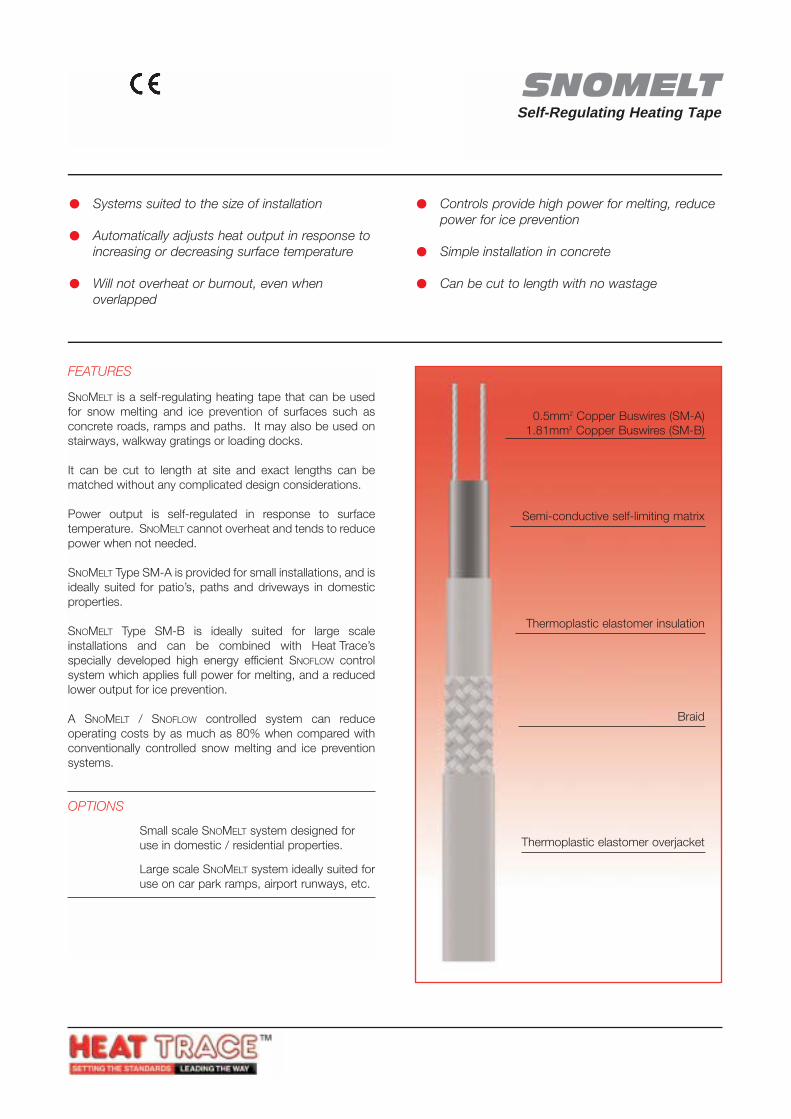
SNOMELTSelf-Regulating Heating Tape
SMElectrical heating tape for snow melting and ice preventionof roads, ramps and walkways
FEATURES
SNOMELT is a self-regulating heating tape that can be usedfor snow melting and ice prevention of surfaces such asconcrete roads, ramps and paths. It may also be used onstairways, walkway gratings or loading docks.
It can be cut to length at site and exact lengths can bematched without any complicated design considerations.
Power output is self-regulated in response to surfacetemperature. SNOMELT cannot overheat and tends to reducepower when not needed.
SNOMELT Type SM-A is provided for small installations, and isideally suited for patio’s, paths and driveways in domesticproperties.
SNOMELT Type SM-B is ideally suited for large scaleinstallations and can be combined with Heat Trace’sspecially developed high energy efficient SNOFLOW controlsystem which applies full power for melting, and a reducedlower output for ice prevention.
A SNOMELT / SNOFLOW controlled system can reduceoperating costs by as much as 80% when compared withconventionally controlled snow melting and ice preventionsystems.
OPTIONS
SM-A Small scale SNOMELT system designed foruse in domestic / residential properties.
SM-B Large scale SNOMELT system ideally suited foruse on car park ramps, airport runways, etc.
Systems suited to the size of installation
Automatically adjusts heat output in response toincreasing or decreasing surface temperature
Will not overheat or burnout, even whenoverlapped
Controls provide high power for melting, reducepower for ice prevention
Simple installation in concrete
Can be cut to length with no wastage
0.5mm2 Copper Buswires (SM-A)1.81mm2 Copper Buswires (SM-B)
Semi-conductive self-limiting matrix
Thermoplastic elastomer insulation
Braid
Thermoplastic elastomer overjacket
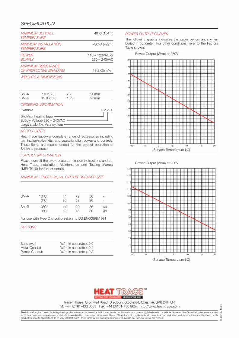
MAXIMUM SURFACE 40°C (104°F)TEMPERATURE
MINIMUM INSTALLATION –30°C (–22°F)TEMPERATURE
POWER 110 – 120VAC orSUPPLY 220 – 240VAC
MAXIMUM RESISTANCEOF PROTECTIVE BRAIDING 18.2 Ohm/km
WEIGHTS & DIMENSIONS
Type Nom. Dims. Weight Min.BendingRef (mm) kg/100m Radius
SM-A 7.9 x 5.6 7.7 20mmSM-B 15.0 x 6.5 18.9 25mm
ORDERING INFORMATION
Example SM2 - B
SNOMELT heating tapeSupply Voltage 220 – 240VACLarge scale SNOMELT system
ACCESSORIES
Heat Trace supply a complete range of accessories includingtermination/splice kits, end seals, junction boxes and controls.These items are recommended for the correct operation ofSNOMELT products.
FURTHER INFORMATION
Please consult the appropriate termination instructions and theHeat Trace Installation, Maintenance and Testing Manual(IMEHT010) for further details.
MAXIMUM LENGTH (m) vs. CIRCUIT BREAKER SIZE
Cat Start-up 230VRef Temperature 6A 10A 16A 20A
SM-A 10°C 44 72 80 -0°C 36 58 80 -
SM-B 10°C 14 22 36 440°C 12 18 30 38
For use with Type C circuit breakers to BS EN60898:1991
FACTORS
Burial in Power OutputMultiplying Factor
Sand (wet) W/m in concrete x 0.9Metal Conduit W/m in concrete x 0.4Plastic Conduit W/m in concrete x 0.3
POWER OUTPUT CURVES
The following graphs indicates the cable performance whenburied in concrete. For other conditions, refer to the FactorsTable shown.
SPECIFICATION
Tracer House, Cromwell Road, Bredbury, Stockport, Cheshire, SK6 2RF, UKTel: +44 (0)161-430 8333 Fax: +44 (0)161-430 8654 http://www.heat-trace.com
The information given herein, including drawings, illustrations and schematics (which are intended for illustration purposes only), is believed to be reliable. However, Heat Trace Ltd makes no warrantiesas to its accuracy or completeness and disclaims any liability in connection with its use. Users of Heat Trace Ltd products should make their own evaluation to determine the suitability of each suchproduct for specific applications. In no way will Heat Trace Ltd be liable for any damages arising out of the misuse, resale or use of the product.
HP
DS
130
10/0
2
SM-A Power Output (W/m) at 230V
Surface Temperature (oC)
SM-B Power Output (W/m) at 230V
Surface Temperature (oC)
-10
15
17
19
21
23
25
27
31
33
35
37
29
-5 0 5 10 2015
-10
70
75
80
85
90
95
100
110
115
120
125
105
-5 0 5 10 2015
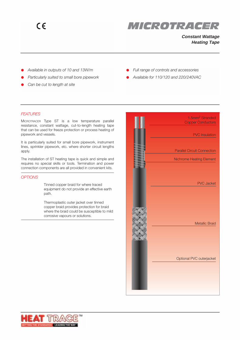
Available in outputs of 10 and 13W/m
Particularly suited to small bore pipework
Can be cut to length at site
Full range of controls and accessories
Available for 110/120 and 220/240VAC
FEATURES
MICROTRACER Type ST is a low temperature parallelresistance, constant wattage, cut-to-length heating tapethat can be used for freeze protection or process heating ofpipework and vessels.
It is particularly suited for small bore pipework, instrumentlines, sprinkler pipework, etc. where shorter circuit lengthsapply.
The installation of ST heating tape is quick and simple andrequires no special skills or tools. Termination and powerconnection components are all provided in convenient kits.
OPTIONS
ST .. C Tinned copper braid for where traced equipment do not provide an effective earth path.
ST .. CT Thermoplastic outer jacket over tinned copper braid provides protection for braid where the braid could be susceptible to mildcorrosive vapours or solutions.
STElectrical heating tape forfrost protection or process heatingof pipework and vessels.
1.5mm2 StrandedCopper Conductors
PVC Insulation
Parallel Circuit Connection
Nichrome Heating Element
PVC Jacket
Metallic Braid
Optional PVC outerjacket
MICROTRACERConstant Wattage
Heating Tape
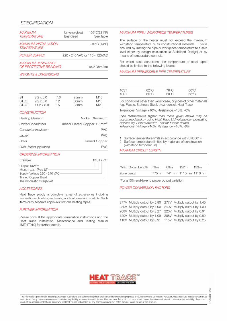
MAXIMUM Un-energised 105°C(221°F)TEMPERATURE Energised See Table
MINIMUM INSTALLATION –10°C (14°F)TEMPERATURE
POWER SUPPLY 220 - 240 VAC or 110 - 120VAC
MAXIMUM RESISTANCEOF PROTECTIVE BRAIDING 18.2 Ohm/km
WEIGHTS & DIMENSIONS
Type Nominal Weight Min. Bending GlandRef Dimensions kg/100m Bending Size
(mm) radius
ST 8.2 x 5.0 7.6 25mm M16ST..C 9.2 x 6.0 12 30mm M16ST..CT 11.2 x 8.0 15 35mm M20
CONSTRUCTION
Heating Element Nickel Chromium
Power Conductors Tinned Plated Copper 1.5mm2
Conductor Insulation PVC
Jacket PVC
Braid Tinned Copper
Over Jacket (optional) PVC
ORDERING INFORMATION
Example 13 ST2-CT
Output 13W/mMICROTRACER Type STSupply Voltage 220 - 240 VACTinned Copper BraidThermoplastic Overjacket
ACCESSORIES
Heat Trace supply a complete range of accessories includingtermination/splice kits, end seals, junction boxes and controls. Suchitems carry separate approvals from the heating tapes.
FURTHER INFORMATION
Please consult the appropriate termination instructions and theHeat Trace Installation, Maintenance and Testing Manual(IMEHT010) for further details.
SPECIFICATION
HP
DS
060
10/0
2
MAXIMUM PIPE / WORKPIECE TEMPERATURES
The surface of the heater must not exceed the maximumwithstand temperature of its constructional materials. This isensured by limiting the pipe or workpiece temperature to a safelevel either by design calculation (a Stabilised Design) or bymeans of temperature controls.
For worst case conditions, the temperature of steel pipesshould be limited to the following levels:-
MAXIMUM PERMISSIBLE PIPE TEMPERATURE
Catalogue Plain Braided Braid/JacketReference (-C) (-CT)
10ST 82oC 76oC 80oC13ST 66oC 60oC 68oC
For conditions other than worst case, or pipes of other materials(eg. Plastic, Stainless Steel, etc.), consult Heat Trace
Tolerances: Voltage +10%; Resistance +10%; -0%
Pipe temperatures higher than those given above may beaccommodated by using Heat Trace Ltd voltage compensatingdevices eg. POWERMATCH™ - call for further details.Tolerances: Voltage +10%; Resistance +10%; -0%
Notes
1 Surface temperature limits in accordance with EN50014.2 Surface temperature limited by materials of construction
(withstand temperature)
MAXIMUM CIRCUIT LENGTH
Catalogue Reference10ST1 13ST1 10ST2 13ST2
*Max. Circuit Length 79m 69m 152m 133m
Zone Length 775mm 741mm 1110mm 1110mm
*For ±10% end-to-end power output variation
POWER CONVERSION FACTORS
115V Heating Tape 230V Heating Tape
277V Multiply output by 5.80 277V Multiply output by 1.45230V Multiply output by 4.00 240V Multiply output by 1.09208V Multiply output by 3.27 220V Multiply output by 0.91120V Multiply output by 1.09 208V Multiply output by 0.82110V Multiply output by 0.91 115V Multiply output by 0.25
Tracer House, Cromwell Road, Bredbury, Stockport, Cheshire, SK6 2RF, UKTel: +44(0)161-430 8333 Fax: +44(0)161-430 8654 http://www.heat-trace.com
The information given herein, including drawings, illustrations and schematics (which are intended for illustration purposes only), is believed to be reliable. However, Heat Trace Ltd makes no warrantiesas to its accuracy or completeness and disclaims any liability in connection with its use. Users of Heat Trace Ltd products should make their own evaluation to determine the suitability of each suchproduct for specific applications. In no way will Heat Trace Ltd be liable for any damages arising out of the misuse, resale or use of the product.
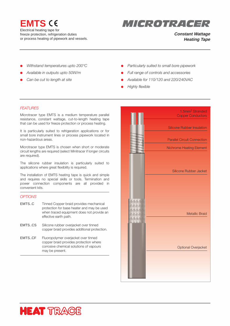
Withstand temperatures upto 200°C
Available in outputs upto 50W/m
Can be cut to length at site
Particularly suited to small bore pipework
Full range of controls and accessories
Available for 110/120 and 220/240VAC
Highly flexible
FEATURES
Microtracer type EMTS is a medium temperature parallelresistance, constant wattage, cut-to-length heating tapethat can be used for freeze protection or process heating.
It is particularly suited to refrigeration applications or forsmall bore instrument lines or process pipework located innon-hazardous areas.
Microtracer type EMTS is chosen when short or moderatecircuit lengths are required (select Minitracer if longer circuitsare required).
The silicone rubber insulation is particularly suited toapplications where great flexibility is required.
The installation of EMTS heating tape is quick and simpleand requires no special skills or tools. Termination andpower connection components are all provided inconvenient kits.
OPTIONS
EMTS..C Tinned Copper braid provides mechanical protection for base heater and may be used when traced equipment does not provide aneffective earth path.
EMTS..CS Silicone rubber overjacket over tinnedcopper braid provides additional protection.
EMTS..CF Fluoropolymer overjacket over tinnedcopper braid provides protection wherecorrosive chemical solutions of vapoursmay be present.
EMTSElectrical heating tape forfreeze protection, refrigeration dutiesor process heating of pipework and vessels.
1.5mm2 StrandedCopper Conductors
Silicone Rubber Insulation
Parallel Circuit Connection
Nichrome Heating Element
Silicone Rubber Jacket
Metallic Braid
Optional Overjacket
MICROTRACERConstant Wattage
Heating Tape
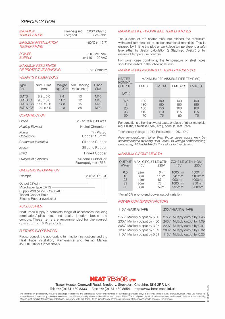
MAXIMUM Un-energised 200°C(392°F)TEMPERATURE Energised See Table
MINIMUM INSTALLATION –80°C (-112°F)TEMPERATURE
POWER 220 - 240 VACSUPPLY or 110 - 120 VAC
MAXIMUM RESISTANCEOF PROTECTIVE BRAIDING 18.2 Ohm/km
WEIGHTS & DIMENSIONS
Type Nom. Dims. Weight Min. Bending GlandRef (mm) kg/100m radius (mm) Size
EMTS 8.2 x 6.0 7.4 10 M16EMTS..C 9.0 x 6.8 11.7 12 M16EMTS..CS 11.0 x 8.8 14.3 15 M20EMTS..CF 10.2 x 8.0 14.3 25 M20
CONSTRUCTION
Grade 2.2 to BS6351:Part 1
Heating Element Nickel Chromium
Power Tin PlatedConductors Copper 1.5mm2
Conductor Insulation Silicone Rubber
Jacket Silicone Rubber
Braid Tinned Copper
Overjacket (Optional) Silicone Rubber orFluoropolymer (FEP)
ORDERING INFORMATION
Example 23 EMTS2-CS
Output 23W/mMicrotracer type EMTSSupply Voltage 220 - 240 VACTinned Copper BraidSilicone Rubber overjacket
ACCESSORIES
Heat Trace supply a complete range of accessories includingtermination/splice kits, end seals, junction boxes andcontrols. These items are recommended for the correctoperation of EMTS products.
FURTHER INFORMATION
Please consult the appropriate termination instructions and theHeat Trace Installation, Maintenance and Testing Manual(IMEHT010) for further details.
SPECIFICATION
Tracer House, Cromwell Road, Bredbury, Stockport, Cheshire, SK6 2RF, UKTel: +44(0)161-430 8333 Fax: +44(0)161-430 8654 http://www.heat-trace.ltd.uk
The information given herein, including drawings, illustrations and schematics (which are intended for illustration purposes only), is believed to be reliable. However, Heat Trace Ltd makes nowarranties as to its accuracy or completeness and disclaims any liability in connection with its use. Users of Heat Trace Ltd products should make their own evaluation to determine the suitabilityof each such product for specific applications. In no way will Heat Trace Ltd be liable for any damages arising out of the misuse, resale or use of the product.
HP
DS
070
09/9
9
MAXIMUM PIPE / WORKPIECE TEMPERATURES
The surface of the heater must not exceed the maximumwithstand temperature of its constructional materials. This isensured by limiting the pipe or workpiece temperature to a safelevel either by design calculation (a Stabilised Design) or bymeans of temperature controls.
For worst case conditions, the temperature of steel pipesshould be limited to the following levels:-
MAXIMUM PIPE/WORKPIECE TEMPERATURES (°C)
HEATER MAXIMUM PERMISSIBLE PIPE TEMP (°C)NOMINALOUTPUT EMTS EMTS-C EMTS-CS EMTS-CF
(W/m)
6.5 190 190 190 19013 180 180 185 18523 150 150 160 16033 110 110 115 11550 70 75 80 75
For conditions other than worst case, or pipes of other materials(eg. Plastic, Stainless Steel, etc.), consult Heat Trace
Tolerances: Voltage +10%; Resistance +10%; -0%
Pipe temperatures higher than those given above may beaccommodated by using Heat Trace Ltd voltage compensatingdevices eg. POWERMATCH™ - call for further details.
MAXIMUM CIRCUIT LENGTH
OUTPUT MAX. CIRCUIT LENGTH* ZONE LENGTH (NOM.)(W/m) 115V 230V 115V 230V
6.5 82m 164m 1000mm 1500mm13 58m 116m 741mm 1100mm23 44m 87m 900mm 1000mm33 36m 73m 1000mm 950mm50 30m 59m 995mm 900mm
*For ±10% end-to-end power output variation
POWER CONVERSION FACTORS
115V HEATING TAPE 230V HEATING TAPE
277V Multiply output by 5.80 277V Multiply output by 1.45230V Multiply output by 4.00 240V Multiply output by 1.09208V Multiply output by 3.27 220V Multiply output by 0.91120V Multiply output by 1.09 208V Multiply output by 0.82110V Multiply output by 0.91 115V Multiply output by 0.25
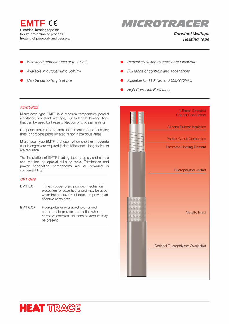
Withstand temperatures upto 200°C
Available in outputs upto 50W/m
Can be cut to length at site
Particularly suited to small bore pipework
Full range of controls and accessories
Available for 110/120 and 220/240VAC
High Corrosion Resistance
FEATURES
Microtracer type EMTF is a medium temperature parallelresistance, constant wattage, cut-to-length heating tapethat can be used for freeze protection or process heating.
It is particularly suited to small instrument impulse, analyserlines, or process pipes located in non-hazardous areas.
Microtracer type EMTF is chosen when short or moderatecircuit lengths are required (select Minitracer if longer circuitsare required).
The installation of EMTF heating tape is quick and simpleand requires no special skills or tools. Termination andpower connection components are all provided inconvenient kits.
OPTIONS
EMTF..C Tinned copper braid provides mechanicalprotection for base heater and may be usedwhen traced equipment does not provide aneffective earth path.
EMTF..CF Fluoropolymer overjacket over tinned copper braid provides protection wherecorrosive chemical solutions of vapours maybe present.
EMTFElectrical heating tape forfreeze protection or processheating of pipework and vessels.
1.5mm2 StrandedCopper Conductors
Silicone Rubber Insulation
Parallel Circuit Connection
Nichrome Heating Element
Fluoropolymer Jacket
Metallic Braid
Optional Fluoropolymer Overjacket
MICROTRACERConstant Wattage
Heating Tape
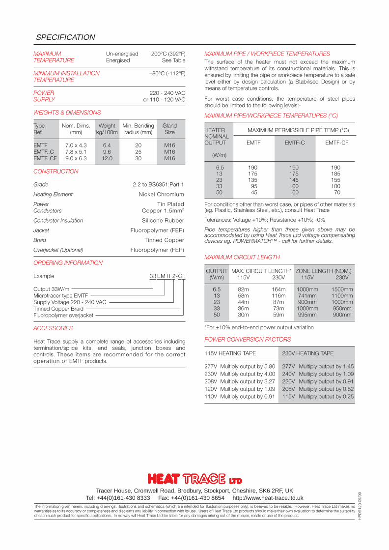
MAXIMUM Un-energised 200°C (392°F)TEMPERATURE Energised See Table
MINIMUM INSTALLATION –80°C (-112°F)TEMPERATURE
POWER 220 - 240 VACSUPPLY or 110 - 120 VAC
WEIGHTS & DIMENSIONS
Type Nom. Dims. Weight Min. Bending GlandRef (mm) kg/100m radius (mm) Size
EMTF 7.0 x 4.3 6.4 20 M16EMTF..C 7.8 x 5.1 9.6 25 M16EMTF..CF 9.0 x 6.3 12.0 30 M16
CONSTRUCTION
Grade 2.2 to BS6351:Part 1
Heating Element Nickel Chromium
Power Tin PlatedConductors Copper 1.5mm2
Conductor Insulation Silicone Rubber
Jacket Fluoropolymer (FEP)
Braid Tinned Copper
Overjacket (Optional) Fluoropolymer (FEP)
ORDERING INFORMATION
Example 33 EMTF2-CF
Output 33W/mMicrotracer type EMTFSupply Voltage 220 - 240 VACTinned Copper BraidFluoropolymer overjacket
ACCESSORIES
Heat Trace supply a complete range of accessories includingtermination/splice kits, end seals, junction boxes andcontrols. These items are recommended for the correctoperation of EMTF products.
SPECIFICATION
Tracer House, Cromwell Road, Bredbury, Stockport, Cheshire, SK6 2RF, UKTel: +44(0)161-430 8333 Fax: +44(0)161-430 8654 http://www.heat-trace.ltd.uk
The information given herein, including drawings, illustrations and schematics (which are intended for illustration purposes only), is believed to be reliable. However, Heat Trace Ltd makes nowarranties as to its accuracy or completeness and disclaims any liability in connection with its use. Users of Heat Trace Ltd products should make their own evaluation to determine the suitabilityof each such product for specific applications. In no way will Heat Trace Ltd be liable for any damages arising out of the misuse, resale or use of the product.
HP
DS
120
09/9
9
MAXIMUM PIPE / WORKPIECE TEMPERATURESThe surface of the heater must not exceed the maximumwithstand temperature of its constructional materials. This isensured by limiting the pipe or workpiece temperature to a safelevel either by design calculation (a Stabilised Design) or bymeans of temperature controls.
For worst case conditions, the temperature of steel pipesshould be limited to the following levels:-
MAXIMUM PIPE/WORKPIECE TEMPERATURES (°C)
HEATER MAXIMUM PERMISSIBLE PIPE TEMP (°C)NOMINALOUTPUT EMTF EMTF-C EMTF-CF
(W/m)
6.5 190 190 19013 175 175 18523 135 145 15533 95 100 10050 45 60 70
For conditions other than worst case, or pipes of other materials(eg. Plastic, Stainless Steel, etc.), consult Heat Trace
Tolerances: Voltage +10%; Resistance +10%; -0%
Pipe temperatures higher than those given above may beaccommodated by using Heat Trace Ltd voltage compensatingdevices eg. POWERMATCH™ - call for further details.
MAXIMUM CIRCUIT LENGTH
OUTPUT MAX. CIRCUIT LENGTH* ZONE LENGTH (NOM.)(W/m) 115V 230V 115V 230V
6.5 82m 164m 1000mm 1500mm13 58m 116m 741mm 1100mm23 44m 87m 900mm 1000mm33 36m 73m 1000mm 950mm50 30m 59m 995mm 900mm
*For ±10% end-to-end power output variation
POWER CONVERSION FACTORS
115V HEATING TAPE 230V HEATING TAPE
277V Multiply output by 5.80 277V Multiply output by 1.45230V Multiply output by 4.00 240V Multiply output by 1.09208V Multiply output by 3.27 220V Multiply output by 0.91120V Multiply output by 1.09 208V Multiply output by 0.82110V Multiply output by 0.91 115V Multiply output by 0.25
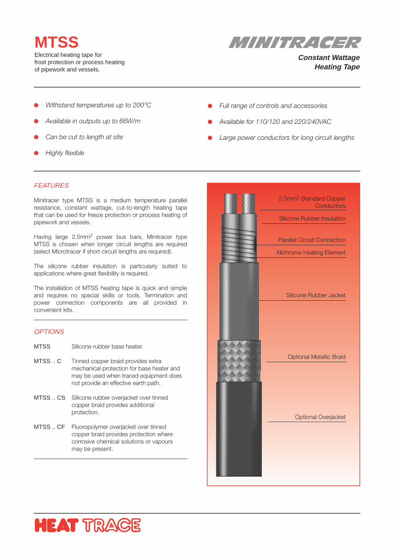
MINITRACERConstant Wattage
Heating Tape
MTSSElectrical heating tape forfrost protection or process heatingof pipework and vessels.
FEATURES
Minitracer type MTSS is a medium temperature parallelresistance, constant wattage, cut-to-length heating tapethat can be used for freeze protection or process heating ofpipework and vessels.
Having large 2.5mm2 power bus bars, Minitracer typeMTSS is chosen when longer circuit lengths are required(select Microtracer if short circuit lengths are required).
The silicone rubber insulation is particularly suited toapplications where great flexibility is required.
The installation of MTSS heating tape is quick and simpleand requires no special skills or tools. Termination andpower connection components are all provided inconvenient kits.
OPTIONS
MTSS Silicone rubber base heater.
MTSS .. C Tinned copper braid provides extramechanical protection for base heater andmay be used when traced equipment doesnot provide an effective earth path.
MTSS .. CS Silicone rubber overjacket over tinnedcopper braid provides additionalprotection.
MTSS .. CF Fluoropolymer overjacket over tinnedcopper braid provides protection wherecorrosive chemical solutions or vapoursmay be present.
Withstand temperatures up to 200°C
Available in outputs up to 66W/m
Can be cut to length at site
Highly flexible
Full range of controls and accessories
Available for 110/120 and 220/240VAC
Large power conductors for long circuit lengths
2.5mm2 Standard CopperConductors
Silicone Rubber Insulation
Parallel Circuit Connection
Nichrome Heating Element
Optional Metallic Braid
Silicone Rubber Jacket
Optional Overjacket
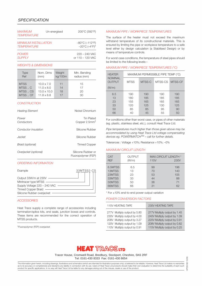
MAXIMUM Un-energised 200°C (392°F)TEMPERATURE
MINIMUM INSTALLATION –80°C (–112°F)TEMPERATURE –20°C (–4°F)†
POWER 220 – 240 VACSUPPLY or 110 – 120 VAC
WEIGHTS & DIMENSIONS
Type Nom. Dims Weight Min. BendingRef (mm) kg/100m radius (mm)
MTSS 10.0 x 7.0 11 15MTSS .. C 11.0 x 8.0 14 17MTSS .. CS 13.0 x 10.0 18 20MTSS .. CF 11.8 x 8.8 17 30
CONSTRUCTION
Heating Element Nickel Chromium
Power Tin PlatedConductors Copper 2.5mm2
Conductor Insulation Silicone Rubber
Jacket Silicone Rubber
Braid (optional) Tinned Copper
Overjacket (optional) Silicone Rubber orFluoropolymer (FEP)
ORDERING INFORMATION
Example 33MTSS2-CS
Output 33W/m at 230VMinitracer type MTSSSupply Voltage 220 – 240 VACTinned Copper BraidSilicone Rubber overjacket
ACCESSORIES
Heat Trace supply a complete range of accessories includingtermination/splice kits, end seals, junction boxes and controls.These items are recommended for the correct operation ofMTSS products.
†Fluoropolymer (FEP) overjacket
MAXIMUM PIPE / WORKPIECE TEMPERATURES
The surface of the heater must not exceed the maximumwithstand temperature of its constructional materials. This isensured by limiting the pipe or workpiece temperature to a safelevel either by design calculation (a Stabilised Design) or bymeans of temperature controls.
For worst case conditions, the temperature of steel pipes shouldbe limited to the following levels:–
MAXIMUM PIPE / WORKPIECE TEMPERATURES (°C)
HEATER MAXIMUM PERMISSIBLE PIPE TEMP (°C)NOMINALOUTPUT MTSS MTSS-C MTSS-CS MTSS-CF
(W/m)
6.5 190 190 190 19013 180 185 185 18523 155 165 165 16533 120 125 130 12550 85 85 95 9066 40 45 55 50
For conditions other than worst case, or pipes of other materials(eg. plastic, stainless steel, etc.), consult Heat Trace Ltd.
Pipe temperatures much higher than those given above may beaccommodated by using Heat Trace Ltd voltage compensatingdevices eg. POWERMATCHTM – call for further details.
Tolerances : Voltage +10%; Resistance +10%; –0%
MAXIMUM CIRCUIT LENGTH
CAT OUTPUT MAX.CIRCUIT LENGTH *REF (W/m) 115V 230V
6.5MTSS 6.5 99 19813MTSS 13 70 14023MTSS 23 53 10533MTSS 33 44 8850MTSS 50 36 7166MTSS 66 31 62
* For ±10% end-to-end power output variation
POWER CONVERSION FACTORS
115V HEATING TAPE 230V HEATING TAPE
277V Multiply output by 5.80 277V Multiply output by 1.45230V Multiply output by 4.00 240V Multiply output by 1.09208V Multiply output by 3.27 220V Multiply output by 0.91120V Multiply output by 1.09 208V Multiply output by 0.82110V Multiply output by 0.91 115V Multiply output by 0.25
SPECIFICATION
Tracer House, Cromwell Road, Bredbury, Stockport, Cheshire, SK6 2RFTel: 0161-430 8333 Fax: 0161-430 8654
The information given herein, including drawings, illustrations and schematics (which are intended for illustration purposes only), is believed to be reliable. However, Heat Trace Ltd makes no warrantiesas to its accuracy or completeness and disclaims any liability in connection with its use. Users of Heat Trace Ltd products should make their own evaluation to determine the suitability of each suchproduct for specific applications. In no way will Heat Trace Ltd be liable for any damages arising out of the misuse, resale or use of the product.
HP
DS
180
10/9
5
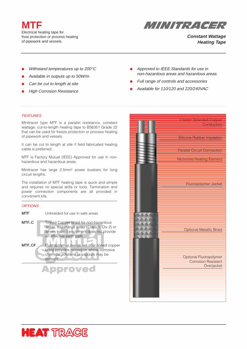
Withstand temperatures up to 200°C
Available in outputs up to 50W/m
Can be cut to length at site
High Corrosion Resistance
Approved to IEEE Standards for use innon-hazardous areas and hazardous areas.
Full range of controls and accessories
Available for 110/120 and 220/240VAC
FEATURES
Minitracer type MTF is a parallel resistance, constantwattage, cut-to-length heating tape to BS6351 Grade 22that can be used for freeze protection or process heatingof pipework and vessels.
It can be cut to length at site if field fabricated heatingcable is preferred.
MTF is Factory Mutual (IEEE) Approved for use in non-hazardous and hazardous areas.
Minitracer has large 2.5mm2 power busbars for longcircuit lengths.
The installation of MTF heating tape is quick and simpleand requires no special skills or tools. Termination andpower connection components are all provided inconvenient kits.
OPTIONS
MTF Unbraided for use in safe areas
MTF..C Tinned Copper braid for non-hazardous areas, hazardous areas (Class 1, Div 2) orwhere traced equipment does not providean effective earth path.
MTF..CF Fluoropolymer overjacket over tinned copper braid provides protection where corrosive
chemical solutions or vapours may be present.
MTFElectrical heating tape forfrost protection or process heatingof pipework and vessels.
2.5mm2 Stranded CopperConductors
Silicone Rubber Insulation
Parallel Circuit Connection
Nichrome Heating Element
Fluoropolymer Jacket
Optional Metallic Braid
Optional FluoropolymerCorrosion Resistant
Overjacket
MINITRACERConstant Wattage
Heating Tape
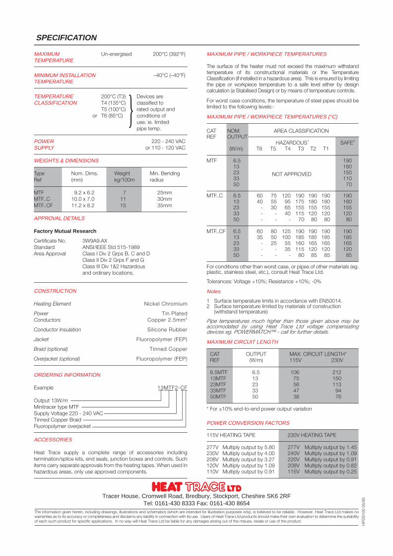
MAXIMUM Un-energised 200°C (392°F)TEMPERATURE
MINIMUM INSTALLATION –40°C (–40°F)TEMPERATURE
TEMPERATURE 200°C (T3) Devices areCLASSIFICATION T4 (135°C) classified to
T5 (100°C) rated output andor T6 (85°C) conditions of
use. ie. limitedpipe temp.
POWER 220 - 240 VACSUPPLY or 110 - 120 VAC
WEIGHTS & DIMENSIONS
Type Nom. Dims. Weight Min. BendingRef (mm) kg/100m radius
MTF 9.2 x 6.2 7 25mmMTF..C 10.0 x 7.0 11 30mmMTF..CF 11.2 x 8.2 15 35mm
APPROVAL DETAILS
Factory Mutual Research
Certificate No. 3W9A9.AXStandard ANSI/IEEE Std 515-1989Area Approval Class I Div 2 Grps B, C and D
Class II Div 2 Grps F and GClass III Div 1&2 Hazardousand ordinary locations.
CONSTRUCTION
Heating Element Nickel Chromium
Power Tin PlatedConductors Copper 2.5mm2
Conductor Insulation Silicone Rubber
Jacket Fluoropolymer (FEP)
Braid (optional) Tinned Copper
Overjacket (optional) Fluoropolymer (FEP)
ORDERING INFORMATION
Example 13MTF2-CF
Output 13W/mMinitracer type MTFSupply Voltage 220 - 240 VACTinned Copper BraidFluoropolymer overjacket
ACCESSORIES
Heat Trace supply a complete range of accessories includingtermination/splice kits, end seals, junction boxes and controls. Suchitems carry separate approvals from the heating tapes. When used inhazardous areas, only use approved components.
SPECIFICATION
Tracer House, Cromwell Road, Bredbury, Stockport, Cheshire SK6 2RFTel: 0161-430 8333 Fax: 0161-430 8654
The information given herein, including drawings, illustrations and schematics (which are intended for illustration purposes only), is believed to be reliable. However, Heat Trace Ltd makes nowarranties as to its accuracy or completeness and disclaims any liability in connection with its use. Users of Heat Trace Ltd products should make their own evaluation to determine the suitabilityof each such product for specific applications. In no way will Heat Trace Ltd be liable for any damages arising out of the misuse, resale or use of the product.
HP
DS
100
05/9
5
MAXIMUM PIPE / WORKPIECE TEMPERATURES
The surface of the heater must not exceed the maximum withstandtemperature of its constructional materials or the TemperatureClassification (if installed in a hazardous area). This is ensured by limitingthe pipe or workpiece temperature to a safe level either by designcalculation (a Stabilised Design) or by means of temperature controls.
For worst case conditions, the temperature of steel pipes should belimited to the following levels:-
MAXIMUM PIPE / WORKPIECE TEMPERATURES (°C)
CAT NOM. AREA CLASSIFICATIONREF OUTPUT
HAZARDOUS1 SAFE2
(W/m) T6 T5 T4 T3 T2 T1
MTF 6.5 19013 18023 15033 11050 70
MTF..C 6.5 60 75 120 190 190 190 19013 40 55 95 175 180 180 18023 - 30 65 155 155 155 15533 - - 40 115 120 120 12050 - - - 70 80 80 80
MTF..CF 6.5 60 80 125 190 190 190 19013 35 50 100 185 185 185 18523 - 25 55 160 165 165 16533 - - 35 115 120 120 12050 - - - 80 85 85 85
For conditions other than worst case, or pipes of other materials (eg.plastic, stainless steel, etc.), consult Heat Trace Ltd.
Tolerances: Voltage +10%; Resistance +10%; -0%
Notes
1 Surface temperature limits in accordance with EN50014.2 Surface temperature limited by materials of construction
(withstand temperature)
Pipe temperatures much higher than those given above may beaccomodated by using Heat Trace Ltd voltage compensatingdevices eg. POWERMATCH™ - call for further details.
MAXIMUM CIRCUIT LENGTH
CAT OUTPUT MAX. CIRCUIT LENGTH*REF (W/m) 115V 230V
6.5MTF 6.5 106 21213MTF 13 75 15023MTF 23 56 11333MTF 33 47 9450MTF 50 38 76
* For ±10% end-to-end power output variation
POWER CONVERSION FACTORS
115V HEATING TAPE 230V HEATING TAPE
277V Multiply output by 5.80 277V Multiply output by 1.45230V Multiply output by 4.00 240V Multiply output by 1.09208V Multiply output by 3.27 220V Multiply output by 0.91120V Multiply output by 1.09 208V Multiply output by 0.82110V Multiply output by 0.91 115V Multiply output by 0.25
NOT APPROVED
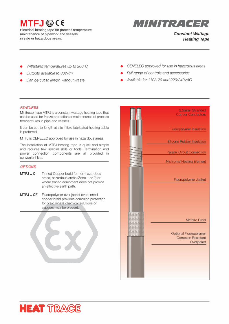
Withstand temperatures up to 200°C
Outputs available to 33W/m
Can be cut to length without waste
CENELEC approved for use in hazardous areas
Full range of controls and accessories
Available for 110/120 and 220/240VAC
FEATURESMinitracer type MTFJ is a constant wattage heating tape thatcan be used for freeze protection or maintenance of processtemperatures in pipe and vessels.
It can be cut-to-length at site if field fabricated heating cableis preferred.
MTFJ is CENELEC approved for use in hazardous areas.
The installation of MTFJ heating tape is quick and simpleand requires few special skills or tools. Termination andpower connection components are all provided inconvenient kits.
OPTIONS
MTFJ .. C Tinned Copper braid for non-hazardous areas, hazardous areas (Zone 1 or 2) or where traced equipment does not provide an effective earth path.
MTFJ .. CF Fluoropolymer over jacket over tinned copper braid provides corrosion protection for braid where chemical solutions or vapours may be present.
MINITRACERConstant Wattage
Heating Tape
MTFJElectrical heating tape for process temperaturemaintenance of pipework and vesselsin safe or hazardous areas.
2.5mm2 StrandedCopper Conductors
Fluoropolymer Insulation
Silicone Rubber Insulation
Parallel Circuit Connection
Nichrome Heating Element
Fluoropolymer Jacket
Metallic Braid
Optional FluoropolymerCorrosion Resistant
Overjacket
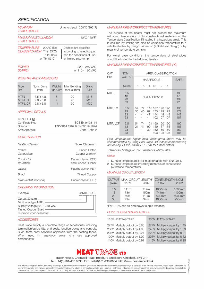
MAXIMUM Un-energised 200°C (392°F)TEMPERATURE
MINIMUM INSTALLATION -40°C (-40°F)TEMPERATURE
TEMPERATURE 200°C (T3) Devices are classifiedCLASSIFICATION T4 (135°C) according to rated output
T5 (100°C) and the conditions of use.or T6 (85°C) ie. limited pipe temp
POWER 220 - 240 VACSUPPLY or 110 - 120 VAC
WEIGHTS AND DIMENSIONS
Type Nom. Dims. Weight Min. Bending GlandRef (mm) kg/100m radius (mm) Size
MTFJ 7.5 x 4.8 6 20 M16MTFJ..C 9.0 x 6.0 9 25 M16MTFJ..CF 9.8 x 6.8 11 30 M20
APPROVAL DETAILS
CENELECCertificate No. SCS Ex 94D3114Standard EN50014:1992 & EN50019:1994Area Approval Zone 1 and 2
CONSTRUCTION
Heating Element Nickel Chromium
Power Tinned PlatedConductors Copper 2.5mm2
Conductor Fluoropolymer (FEP)Insulation and Silicone Rubber
Jacket Fluoropolymer (FEP)
Braid Tinned Copper
Over Jacket (optional) Fluoropolymer (FEP)
ORDERING INFORMATION
Example 23MTFJ2-CF
Output 23W/mMinitracer type MTFJSupply Voltage 220 - 240 VACTinned Copper BraidFluoropolymer overjacket
ACCESSORIES
Heat Trace supply a complete range of accessories includingtermination/splice kits, end seals, junction boxes and controls.Such items carry separate approvals from the heating tapes.When used in hazardous areas, only use approvedcomponents.
SPECIFICATION
MAXIMUM PIPE/WORKPIECE TEMPERATURES
The surface of the heater must not exceed the maximumwithstand temperature of its constructional materials or theTemperature Classification (if installed in a hazardous area). Thisis ensured by limiting the pipe or workpiece temperature to asafe level either by design calculation (a Stabilised Design) or bymeans of temperature controls.
For worst case conditions, the temperature of steel pipesshould be limited to the following levels:-
MAXIMUM PIPE/WORKPIECE TEMPERATURES (°C)
CAT NOM AREA CLASSIFICATIONREF OUTPUT
HAZARDOUS1 SAFE2
(W/m) T6 T5 T4 T3 T2 T1
MTFJ 6.5 19013 17623 13933 97
MTFJ..C 6.5 54 72 115 187 190 190 19013 30 45 87 173 179 179 17923 - - 47 144 149 149 14933 - - - 102 107 107 107
MTFJ..CF 6.5 54 74 121 190 190 190 19013 21 41 90 180 187 185 18523 - - 39 152 159 159 15933 - - - 103 108 108 108
Pipe temperatures higher than those given above may beaccommodated by using Heat Trace Ltd voltage compensatingdevices eg. POWERMATCH™ - call for further details.
Tolerances: Voltage +10%; Resistance +10%; -0%
Notes
1 Surface temperature limits in accordance with EN50014.2 Surface temperature limited by materials of construction
(withstand temperature)
MAXIMUM CIRCUIT LENGTH
OUTPUT MAX. CIRCUIT LENGTH* ZONE LENGTH (NOM.)(W/m) 115V 230V 115V 230V
6.5 111m 212m 1000mm 1500mm13 78m 150m 741mm 1100mm23 59m 113m 900mm 1000mm33 49m 94m 1000mm 950mm
*For ±10% end-to-end power output variation
POWER CONVERSION FACTORS
115V HEATING TAPE 230V HEATING TAPE
277V Multiply output by 5.80 277V Multiply output by 1.45230V Multiply output by 4.00 240V Multiply output by 1.09208V Multiply output by 3.27 220V Multiply output by 0.91120V Multiply output by 1.09 208V Multiply output by 0.82110V Multiply output by 0.91 115V Multiply output by 0.25
Tracer House, Cromwell Road, Bredbury, Stockport, Cheshire, SK6 2RFTel: +44(0)161-430 8333 Fax: +44(0)161-430 8654 http://www.heat-trace.ltd.uk
The information given herein, including drawings, illustrations and schematics (which are intended for illustration purposes only), is believed to be reliable. However, Heat Trace Ltd makes nowarranties as to its accuracy or completeness and disclaims any liability in connection with its use. Users of Heat Trace Ltd products should make their own evaluation to determine the suitabilityof each such product for specific applications. In no way will Heat Trace Ltd be liable for any damages arising out of the misuse, resale or use of the product.
HP
DS
030
09/9
9
NOT APPROVED
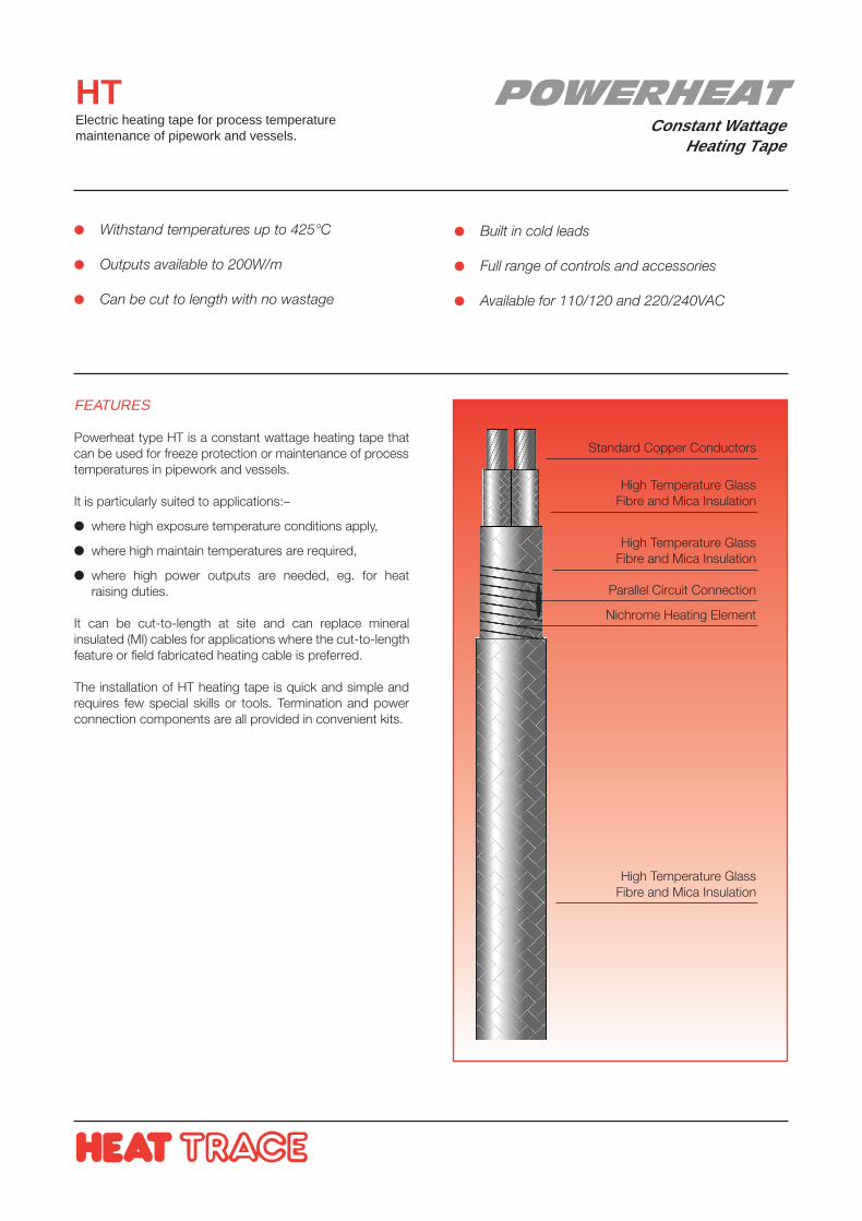
POWERHEATConstant Wattage
Heating Tape
HTElectric heating tape for process temperaturemaintenance of pipework and vessels.
FEATURES
Powerheat type HT is a constant wattage heating tape thatcan be used for freeze protection or maintenance of processtemperatures in pipework and vessels.
It is particularly suited to applications:–
where high exposure temperature conditions apply,
where high maintain temperatures are required,
where high power outputs are needed, eg. for heatraising duties.
It can be cut-to-length at site and can replace mineralinsulated (MI) cables for applications where the cut-to-lengthfeature or field fabricated heating cable is preferred.
The installation of HT heating tape is quick and simple andrequires few special skills or tools. Termination and powerconnection components are all provided in convenient kits.
Withstand temperatures up to 425°C
Outputs available to 200W/m
Can be cut to length with no wastage
Built in cold leads
Full range of controls and accessories
Available for 110/120 and 220/240VAC
Standard Copper Conductors
High Temperature GlassFibre and Mica Insulation
High Temperature GlassFibre and Mica Insulation
Parallel Circuit Connection
Nichrome Heating Element
High Temperature GlassFibre and Mica Insulation
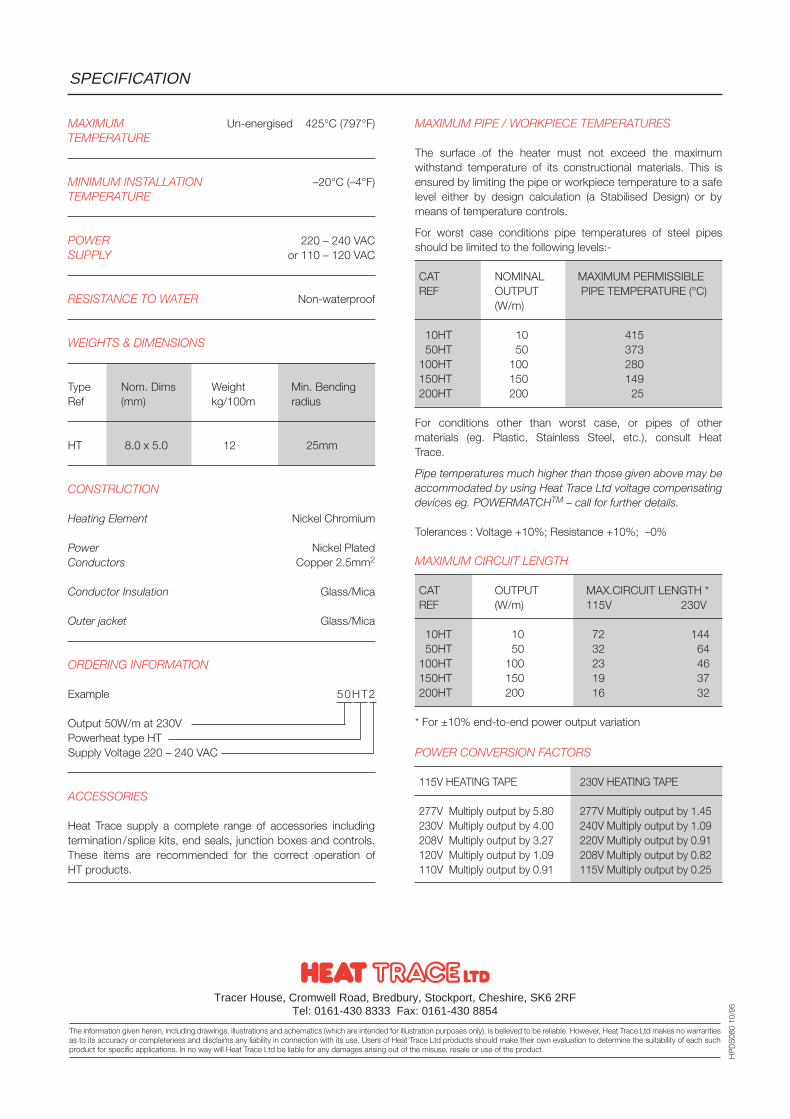
MAXIMUM Un-energised 425°C (797°F)TEMPERATURE
MINIMUM INSTALLATION –20°C (–4°F)TEMPERATURE
POWER 220 – 240 VACSUPPLY or 110 – 120 VAC
RESISTANCE TO WATER Non-waterproof
WEIGHTS & DIMENSIONS
Type Nom. Dims Weight Min. BendingRef (mm) kg/100m radius
HT 8.0 x 5.0 12 25mm
CONSTRUCTION
Heating Element Nickel Chromium
Power Nickel PlatedConductors Copper 2.5mm2
Conductor Insulation Glass/Mica
Outer jacket Glass/Mica
ORDERING INFORMATION
Example 50HT2
Output 50W/m at 230VPowerheat type HTSupply Voltage 220 – 240 VAC
ACCESSORIES
Heat Trace supply a complete range of accessories includingtermination/splice kits, end seals, junction boxes and controls.These items are recommended for the correct operation ofHT products.
MAXIMUM PIPE / WORKPIECE TEMPERATURES
The surface of the heater must not exceed the maximumwithstand temperature of its constructional materials. This isensured by limiting the pipe or workpiece temperature to a safelevel either by design calculation (a Stabilised Design) or bymeans of temperature controls.
For worst case conditions pipe temperatures of steel pipesshould be limited to the following levels:-
CAT NOMINAL MAXIMUM PERMISSIBLEREF OUTPUT PIPE TEMPERATURE (°C)
(W/m)
10HT 10 41550HT 50 373
100HT 100 280150HT 150 149200HT 200 25
For conditions other than worst case, or pipes of othermaterials (eg. Plastic, Stainless Steel, etc.), consult HeatTrace.
Pipe temperatures much higher than those given above may beaccommodated by using Heat Trace Ltd voltage compensatingdevices eg. POWERMATCHTM – call for further details.
Tolerances : Voltage +10%; Resistance +10%; –0%
MAXIMUM CIRCUIT LENGTH
CAT OUTPUT MAX.CIRCUIT LENGTH *REF (W/m) 115V 230V
10HT 10 72 14450HT 50 32 64
100HT 100 23 46150HT 150 19 37200HT 200 16 32
* For ±10% end-to-end power output variation
POWER CONVERSION FACTORS
115V HEATING TAPE 230V HEATING TAPE
277V Multiply output by 5.80 277V Multiply output by 1.45230V Multiply output by 4.00 240V Multiply output by 1.09208V Multiply output by 3.27 220V Multiply output by 0.91120V Multiply output by 1.09 208V Multiply output by 0.82110V Multiply output by 0.91 115V Multiply output by 0.25
SPECIFICATION
Tracer House, Cromwell Road, Bredbury, Stockport, Cheshire, SK6 2RFTel: 0161-430 8333 Fax: 0161-430 8854
The information given herein, including drawings, illustrations and schematics (which are intended for illustration purposes only), is believed to be reliable. However, Heat Trace Ltd makes no warrantiesas to its accuracy or completeness and disclaims any liability in connection with its use. Users of Heat Trace Ltd products should make their own evaluation to determine the suitability of each suchproduct for specific applications. In no way will Heat Trace Ltd be liable for any damages arising out of the misuse, resale or use of the product.
HP
DS
080
10/9
5
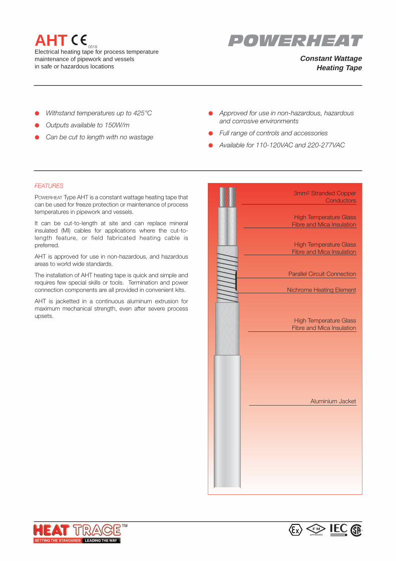
Withstand temperatures up to 425°C
Outputs available to 150W/m
Can be cut to length with no wastage
Approved for use in non-hazardous, hazardousand corrosive environments
Full range of controls and accessories
Available for 110-120VAC and 220-277VAC
FEATURES
POWERHEAT Type AHT is a constant wattage heating tape thatcan be used for freeze protection or maintenance of processtemperatures in pipework and vessels.
It can be cut-to-length at site and can replace mineralinsulated (MI) cables for applications where the cut-to-length feature, or field fabricated heating cable ispreferred.
AHT is approved for use in non-hazardous, and hazardousareas to world wide standards.
The installation of AHT heating tape is quick and simple andrequires few special skills or tools. Termination and powerconnection components are all provided in convenient kits.
AHT is jacketted in a continuous aluminum extrusion formaximum mechanical strength, even after severe processupsets.
AHTElectrical heating tape for process temperaturemaintenance of pipework and vesselsin safe or hazardous locations
3mm2 Stranded CopperConductors
High Temperature GlassFibre and Mica Insulation
High Temperature GlassFibre and Mica Insulation
Parallel Circuit Connection
Nichrome Heating Element
High Temperature GlassFibre and Mica Insulation
Aluminium Jacket
POWERHEATConstant Wattage
Heating Tape
0518
F M
APPROVED
R
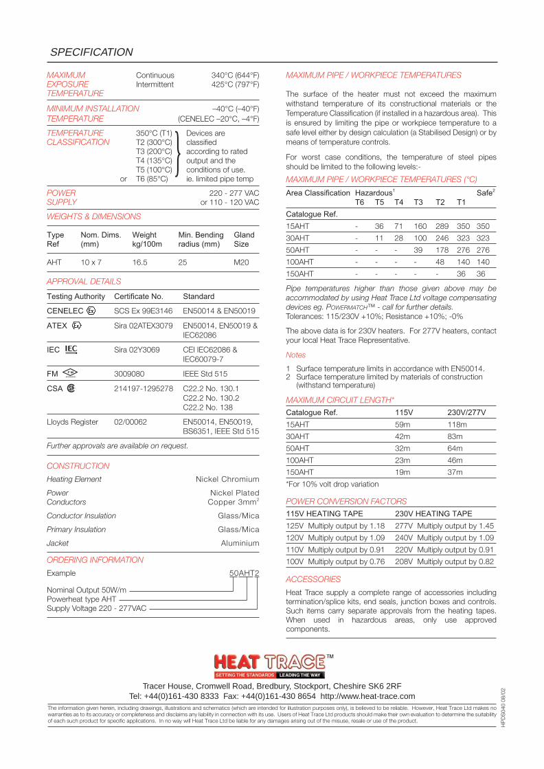
MAXIMUM Continuous 340°C (644°F)EXPOSURE Intermittent 425°C (797°F)TEMPERATURE
MINIMUM INSTALLATION –40°C (–40°F)TEMPERATURE (CENELEC –20°C, –4°F)
TEMPERATURE 350°C (T1) Devices areCLASSIFICATION T2 (300°C) classified
T3 (200°C) according to ratedT4 (135°C) output and theT5 (100°C) conditions of use.
or T6 (85°C) ie. limited pipe temp
POWER 220 - 277 VACSUPPLY or 110 - 120 VAC
WEIGHTS & DIMENSIONS
Type Nom. Dims. Weight Min. Bending GlandRef (mm) kg/100m radius (mm) Size
AHT 10 x 7 16.5 25 M20
APPROVAL DETAILS
Testing Authority Certificate No. Standard
CENELEC SCS Ex 99E3146 EN50014 & EN50019
ATEX Sira 02ATEX3079 EN50014, EN50019 &IEC62086
IEC Sira 02Y3069 CEI IEC62086 &IEC60079-7
FM 3009080 IEEE Std 515
CSA 214197-1295278 C22.2 No. 130.1C22.2 No. 130.2C22.2 No. 138
Lloyds Register 02/00062 EN50014, EN50019,BS6351, IEEE Std 515
Further approvals are available on request.
CONSTRUCTION
Heating Element Nickel Chromium
Power Nickel PlatedConductors Copper 3mm2
Conductor Insulation Glass/Mica
Primary Insulation Glass/Mica
Jacket Aluminium
ORDERING INFORMATION
Example 50AHT2
Nominal Output 50W/mPowerheat type AHTSupply Voltage 220 - 277VAC
SPECIFICATION
Tracer House, Cromwell Road, Bredbury, Stockport, Cheshire SK6 2RFTel: +44(0)161-430 8333 Fax: +44(0)161-430 8654 http://www.heat-trace.com
The information given herein, including drawings, illustrations and schematics (which are intended for illustration purposes only), is believed to be reliable. However, Heat Trace Ltd makes nowarranties as to its accuracy or completeness and disclaims any liability in connection with its use. Users of Heat Trace Ltd products should make their own evaluation to determine the suitabilityof each such product for specific applications. In no way will Heat Trace Ltd be liable for any damages arising out of the misuse, resale or use of the product.
HP
DS
040
08/0
2
MAXIMUM PIPE / WORKPIECE TEMPERATURES
The surface of the heater must not exceed the maximumwithstand temperature of its constructional materials or theTemperature Classification (if installed in a hazardous area). Thisis ensured by limiting the pipe or workpiece temperature to asafe level either by design calculation (a Stabilised Design) or bymeans of temperature controls.
For worst case conditions, the temperature of steel pipesshould be limited to the following levels:-
MAXIMUM PIPE / WORKPIECE TEMPERATURES (°C)
Area Classification Hazardous1 Safe2
T6 T5 T4 T3 T2 T1Catalogue Ref.15AHT - 36 71 160 289 350 350
30AHT - 11 28 100 246 323 323
50AHT - - - 39 178 276 276
100AHT - - - - 48 140 140
150AHT - - - - - 36 36
Pipe temperatures higher than those given above may beaccommodated by using Heat Trace Ltd voltage compensatingdevices eg. POWERMATCH™ - call for further details.Tolerances: 115/230V +10%; Resistance +10%; -0%
The above data is for 230V heaters. For 277V heaters, contactyour local Heat Trace Representative.
Notes
1 Surface temperature limits in accordance with EN50014.2 Surface temperature limited by materials of construction
(withstand temperature)
MAXIMUM CIRCUIT LENGTH*
Catalogue Ref. 115V 230V/277V15AHT 59m 118m
30AHT 42m 83m
50AHT 32m 64m
100AHT 23m 46m
150AHT 19m 37m
*For 10% volt drop variation
POWER CONVERSION FACTORS
115V HEATING TAPE 230V HEATING TAPE125V Multiply output by 1.18 277V Multiply output by 1.45
120V Multiply output by 1.09 240V Multiply output by 1.09
110V Multiply output by 0.91 220V Multiply output by 0.91
100V Multiply output by 0.76 208V Multiply output by 0.82
ACCESSORIES
Heat Trace supply a complete range of accessories includingtermination/splice kits, end seals, junction boxes and controls.Such items carry separate approvals from the heating tapes.When used in hazardous areas, only use approvedcomponents.
F M
APPROVED
R
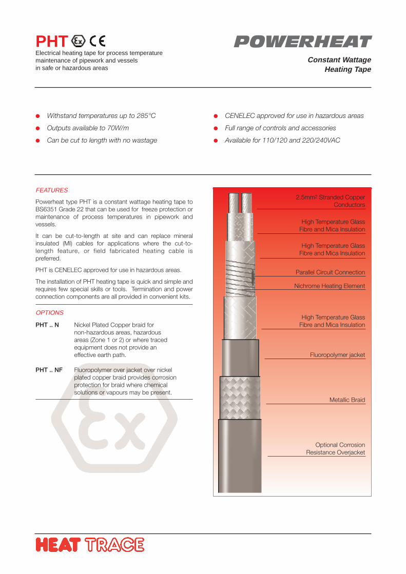
Withstand temperatures up to 285°C
Outputs available to 70W/m
Can be cut to length with no wastage
CENELEC approved for use in hazardous areas
Full range of controls and accessories
Available for 110/120 and 220/240VAC
FEATURES
Powerheat type PHT is a constant wattage heating tape toBS6351 Grade 22 that can be used for freeze protection ormaintenance of process temperatures in pipework andvessels.
It can be cut-to-length at site and can replace mineralinsulated (MI) cables for applications where the cut-to-length feature, or field fabricated heating cable ispreferred.
PHT is CENELEC approved for use in hazardous areas.
The installation of PHT heating tape is quick and simple andrequires few special skills or tools. Termination and powerconnection components are all provided in convenient kits.
OPTIONS
PHT .. N Nickel Plated Copper braid for non-hazardous areas, hazardous areas (Zone 1 or 2) or where tracedequipment does not provide aneffective earth path.
PHT .. NF Fluoropolymer over jacket over nickel plated copper braid provides corrosionprotection for braid where chemicalsolutions or vapours may be present.
PHTElectrical heating tape for process temperaturemaintenance of pipework and vesselsin safe or hazardous areas
POWERHEATConstant Wattage
Heating Tape
2.5mm2 Stranded CopperConductors
High Temperature GlassFibre and Mica Insulation
High Temperature GlassFibre and Mica Insulation
Parallel Circuit Connection
Nichrome Heating Element
High Temperature GlassFibre and Mica Insulation
Fluoropolymer jacket
Metallic Braid
Optional CorrosionResistance Overjacket
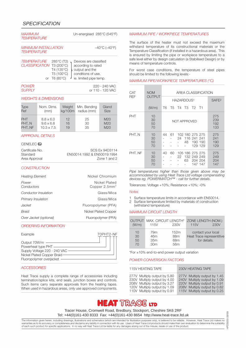
MAXIMUM Un-energised 285°C (545°F)TEMPERATURE
MINIMUM INSTALLATION –40°C (–40°F)TEMPERATURE
TEMPERATURE 285°C (T2) Devices are classifiedCLASSIFICATION T3 (200°C) according to rated
T4 (135°C) output and theT5 (100°C) conditions of use.
or T6 (85°C) ie. limited pipe temp.
POWER 220 - 240 VACSUPPLY or 110 - 120 VAC
WEIGHTS & DIMENSIONS
Type Nom. Dims. Weight Min. Bending GlandRef (mm) kg/100m radius (mm) Size
PHT 8.8 x 6.0 12 25 M20PHT..N 9.6 x 6.8 16 30 M20PHT..NF 10.3 x 7.5 19 35 M20
APPROVAL DETAILS
CENELEC
Certificate No. SCS Ex 94D3114Standard EN50014:1992 & EN50019:1994Area Approval Zone 1 and 2
CONSTRUCTION
Heating Element Nickel Chromium
Power Nickel PlatedConductors Copper 2.5mm2
Conductor Insulation Glass/Mica
Primary Insulation Glass/Mica
Jacket Fluoropolymer (PFA)
Braid Nickel Plated Copper
Over Jacket (optional) Fluoropolymer (PFA)
ORDERING INFORMATION
Example 70PHT2-NF
Output 70W/mPowerheat type PHTSupply Voltage 220 - 240 VACNickel Plated Copper BraidFluoropolymer overjacket
ACCESSORIES
Heat Trace supply a complete range of accessories includingtermination/splice kits, end seals, junction boxes and controls.Such items carry separate approvals from the heating tapes.When used in hazardous areas, only use approved components.
SPECIFICATION
Tracer House, Cromwell Road, Bredbury, Stockport, Cheshire SK6 2RFTel: +44(0)161-430 8333 Fax: +44(0)161-430 8654 http://www.heat-trace.ltd.uk
The information given herein, including drawings, illustrations and schematics (which are intended for illustration purposes only), is believed to be reliable. However, Heat Trace Ltd makes nowarranties as to its accuracy or completeness and disclaims any liability in connection with its use. Users of Heat Trace Ltd products should make their own evaluation to determine the suitabilityof each such product for specific applications. In no way will Heat Trace Ltd be liable for any damages arising out of the misuse, resale or use of the product.
HP
DS
050
09/9
9
MAXIMUM PIPE / WORKPIECE TEMPERATURES
The surface of the heater must not exceed the maximumwithstand temperature of its constructional materials or theTemperature Classification (if installed in a hazardous area). Thisis ensured by limiting the pipe or workpiece temperature to asafe level either by design calculation (a Stabilised Design) or bymeans of temperature controls.
For worst case conditions, the temperature of steel pipesshould be limited to the following levels:-
MAXIMUM PIPE/WORKPIECE TEMPERATURES (°C)
CAT NOM AREA CLASSIFICATIONREF OUTPUT
HAZARDOUS1 SAFE2
(W/m) T6 T5 T4 T3 T2 T1
PHT 10 27530 23950 19270 133
PHT..N 10 44 61 102 180 275 275 27530 - - 24 116 241 241 24150 - - - 48 190 190 19070 - - - - 129 129 129
PHT..NF 10 40 60 105 186 275 275 27530 - - 22 132 249 249 24950 - - - 63 204 204 20470 - - - - 147 147 147
Pipe temperatures higher than those given above may beaccommodated by using Heat Trace Ltd voltage compensatingdevices eg. POWERMATCH™ - call for further details.
Tolerances: Voltage +10%; Resistance +10%; -0%
Notes
1 Surface temperature limits in accordance with EN50014.2 Surface temperature limited by materials of construction
(withstand temperature)
MAXIMUM CIRCUIT LENGTH
OUTPUT MAX. CIRCUIT LENGTH* ZONE LENGTH (NOM.)(W/m) 115V 230V 115V 230V
10 79m 152m contact your local30 46m 88m Heat Trace representitive50 35m 68m for details.70 30m 56m
*For ±10% end-to-end power output variation
POWER CONVERSION FACTORS
115V HEATING TAPE 230V HEATING TAPE
277V Multiply output by 5.80 277V Multiply output by 1.45230V Multiply output by 4.00 240V Multiply output by 1.09208V Multiply output by 3.27 220V Multiply output by 0.91120V Multiply output by 1.09 208V Multiply output by 0.82110V Multiply output by 0.91 115V Multiply output by 0.25
NOT APPROVED
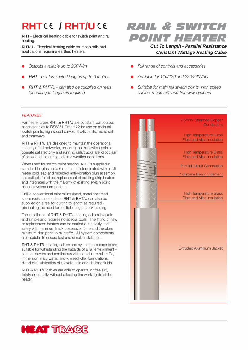
Outputs available up to 200W/m
RHT - pre-terminated lengths up to 6 metres
RHT & RHT/U - can also be supplied on reelsfor cutting to length as required
Full range of controls and accessories
Available for 110/120 and 220/240VAC
Suitable for main rail switch points, high speedcurves, mono rails and tramway systems
FEATURES
Rail heater types RHT & RHT/U are constant watt outputheating cables to BS6351 Grade 22 for use on main railswitch points, high speed curves, 3rd/live rails, mono railsand tramways.
RHT & RHT/U are designed to maintain the operationalintegrity of rail networks, ensuring that rail switch pointsoperate satisfactorily and running rails/tracks are kept clearof snow and ice during adverse weather conditions.
When used for switch point heating, RHT is supplied instandard lengths up to 6 metres, pre-terminated with a 1.5metre cold lead and moulded anti-vibration plug assembly.It is suitable for direct replacement of existing strip heatersand integrates with the majority of existing switch pointheating system components.
Unlike conventional mineral insulated, metal sheathed,series resistance heaters, RHT & RHT/U can also besupplied on a reel for cutting to length as required -eliminating the need for multiple length stock holding.
The installation of RHT & RHT/U heating cables is quickand simple and requires no special tools. The fitting of newor replacement heaters can be carried out quickly andsafely with minimum track possession time and thereforeminimum disruption to rail traffic. All system componentsare modular to ensure fast and simple installation.
RHT & RHT/U heating cables and system components aresuitable for withstanding the hazards of a rail environment -such as severe and continuous vibration due to rail traffic,immersion in icy water, snow, weed killer formulations,diesel oils, lubrication oils, oxalic acid and de-icing fluids.
RHT & RHT/U cables are able to operate in “free air”,totally or partially, without affecting the working life of theheater.
RHT / RHT/URHT - Electrical heating cable for switch point and railheating.
RHT/U - Electrical heating cable for mono rails andapplications requiring earthed heaters.
2.5mm2 Stranded CopperConductors
High Temperature GlassFibre and Mica Insulation
High Temperature GlassFibre and Mica Insulation
Parallel Circuit Connection
Nichrome Heating Element
High Temperature GlassFibre and Mica Insulation
Extruded Aluminium Jacket
RAIL & SWITCHPOINT HEATER
Cut To Length - Parallel ResistanceConstant Wattage Heating Cable
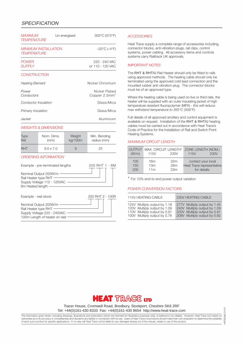
SPECIFICATION
Tracer House, Cromwell Road, Bredbury, Stockport, Cheshire SK6 2RFTel: +44(0)161-430 8333 Fax: +44(0)161-430 8654 http://www.heat-trace.com
The information given herein, including drawings, illustrations and schematics (which are intended for illustration purposes only), is believed to be reliable. However, Heat Trace Ltd makes nowarranties as to its accuracy or completeness and disclaims any liability in connection with its use. Users of Heat Trace Ltd products should make their own evaluation to determine the suitabilityof each such product for specific applications. In no way will Heat Trace Ltd be liable for any damages arising out of the misuse, resale or use of the product.
HP
DS
390
01/0
1
MAXIMUM Un-energised 350°C (572°F)TEMPERATURE
MINIMUM INSTALLATION –20°C (–4°F)TEMPERATURE
POWER 220 - 240 VACSUPPLY or 110 - 120 VAC
CONSTRUCTION
Heating Element Nickel Chromium
Power Nickel PlatedConductors Copper 2.5mm2
Conductor Insulation Glass/Mica
Primary Insulation Glass/Mica
Jacket Aluminium
WEIGHTS & DIMENSIONS
Type Nom. Dims. Weight Min. BendingRef (mm) kg/100m radius (mm)
RHT 9.0 x 7.0 9 25
ORDERING INFORMATION
Example - pre-terminated lengths 200 RHT 1 - 6M
Nominal Output 200W/mRail Heater type RHTSupply Voltage 110 - 120VAC6m Heated length
Example - reel stock 200 RHT 2 - 100R
Nominal Output 200W/mRail Heater type RHTSupply Voltage 220 - 240VAC100m Length of heater on reel
ACCESSORIES
Heat Trace supply a complete range of accessories including,connector blocks, anti-vibration plugs, rail clips, controlsystems, power cabling. All accessory items and controlssystems carry Railtrack UK approvals.
IMPORTANT NOTES
The RHT & RHT/U Rail Heater should only be fitted to railsusing approved methods. The heating cable should only beterminated using the approved cold lead connection and themoulded rubber anti-vibration plug. The connector blocksmust be of an approved type.
Where the heating cable is being used on live or third rails, theheater will be supplied with an outer insulating jacket of hightemperature resistant fluoropolymer (MFA) - this will reducemax withstand temperature to 265°C (509°F).
Full details of all approved ancillary and control equipment isavailable on request. Installation of the RHT & RHT/U heatingcables must be carried out in accordance with Heat Trace’sCode of Practice for the Installation of Rail and Switch PointHeating Systems.
MAXIMUM CIRCUIT LENGTH
OUTPUT MAX. CIRCUIT LENGTH* ZONE LENGTH (NOM.)(W/m) 115V 230V 115V 230V
100 16m 32m contact your local150 13m 26m Heat Trace representative200 11m 23m for details.
* For 10% end-to-end power output variation
POWER CONVERSION FACTORS
115V HEATING CABLE 230V HEATING CABLE
125V Multiply output by 1.18 277V Multiply output by 1.45120V Multiply output by 1.09 240V Multiply output by 1.09110V Multiply output by 0.91 220V Multiply output by 0.91100V Multiply output by 0.76 208V Multiply output by 0.82
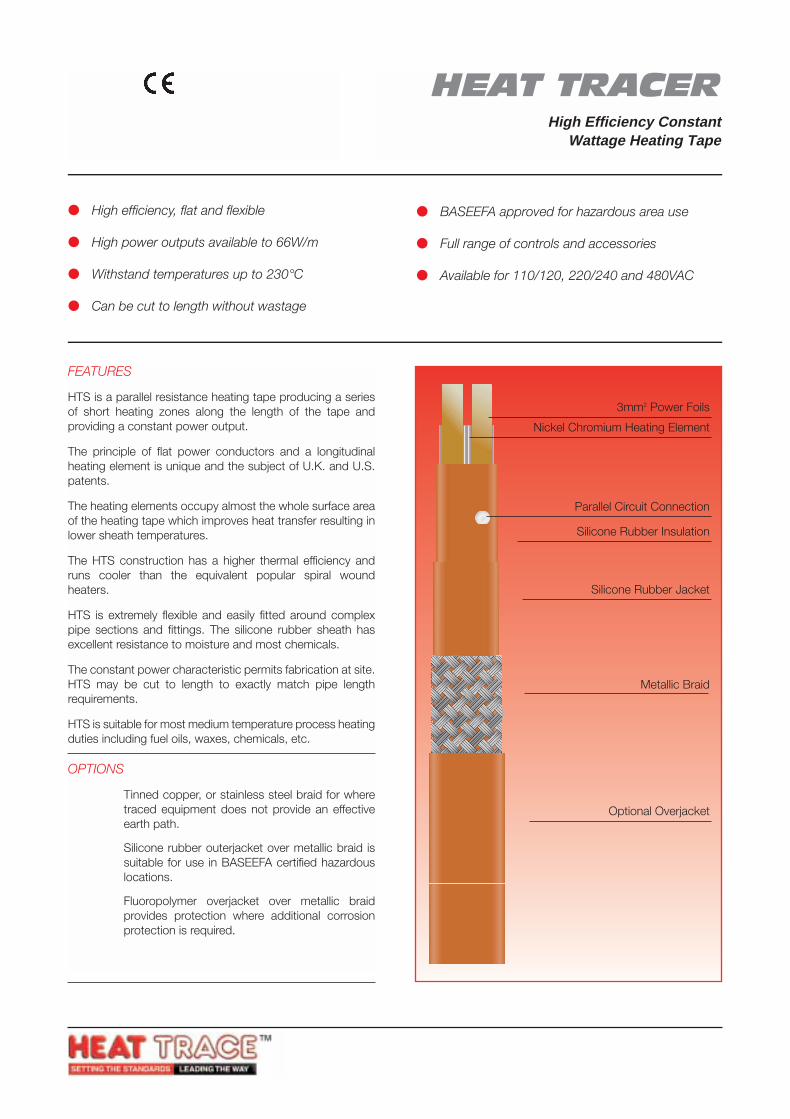
HEAT TRACER(PATENTED)
High Efficiency ConstantWattage Heating Tape
HTSElectrical heating tape for processtemperature maintenance of pipeworkand vessels in safe and hazardous areas
FEATURES
HTS is a parallel resistance heating tape producing a seriesof short heating zones along the length of the tape andproviding a constant power output.
The principle of flat power conductors and a longitudinalheating element is unique and the subject of U.K. and U.S.patents.
The heating elements occupy almost the whole surface areaof the heating tape which improves heat transfer resulting inlower sheath temperatures.
The HTS construction has a higher thermal efficiency andruns cooler than the equivalent popular spiral woundheaters.
HTS is extremely flexible and easily fitted around complexpipe sections and fittings. The silicone rubber sheath hasexcellent resistance to moisture and most chemicals.
The constant power characteristic permits fabrication at site.HTS may be cut to length to exactly match pipe lengthrequirements.
HTS is suitable for most medium temperature process heatingduties including fuel oils, waxes, chemicals, etc.
OPTIONS
HTS ..* Tinned copper, or stainless steel braid for wheretraced equipment does not provide an effectiveearth path.
HTS ..*S Silicone rubber outerjacket over metallic braid issuitable for use in BASEEFA certified hazardouslocations.
HTS ..*F Fluoropolymer overjacket over metallic braidprovides protection where additional corrosionprotection is required.
High efficiency, flat and flexible
High power outputs available to 66W/m
Withstand temperatures up to 230°C
Can be cut to length without wastage
BASEEFA approved for hazardous area use
Full range of controls and accessories
Available for 110/120, 220/240 and 480VAC
3mm2 Power Foils
Silicone Rubber Jacket
Metallic Braid
Optional Overjacket
Silicone Rubber Insulation
Parallel Circuit Connection
Nickel Chromium Heating Element
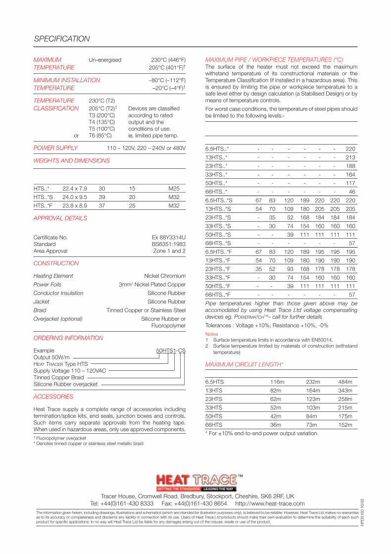
MAXIMUM Un-energised 230°C (446°F)TEMPERATURE 205°C (401°F)†
MINIMUM INSTALLATION –80°C (–112°F)TEMPERATURE –20°C (–4°F)†
TEMPERATURE 230°C (T2)CLASSIFICATION 205°C (T2)† Devices are classified
T3 (200°C) according to ratedT4 (135°C) output and theT5 (100°C) conditions of use.
or T6 (85°C) ie. limited pipe temp.
POWER SUPPLY 110 – 120V, 220 – 240V or 480V
WEIGHTS AND DIMENSIONS
Type Nom. Dims. Weight Min. Bending GlandRef (mm) kg/100m radius (mm) SizeHTS..* 22.4 x 7.9 30 15 M25
HTS..*S 24.0 x 9.5 39 20 M32
HTS..*F 23.8 x 8.9 37 25 M32
APPROVAL DETAILS
BASEEFACertificate No. Ex 88Y3314UStandard BS6351:1983Area Approval Zone 1 and 2
CONSTRUCTION
Heating Element Nickel Chromium
Power Foils 3mm2 Nickel Plated Copper
Conductor Insulation Silicone Rubber
Jacket Silicone Rubber
Braid Tinned Copper or Stainless Steel
Overjacket (optional) Silicone Rubber orFluoropolymer
ORDERING INFORMATION
Example 50HTS1-CSOutput 50W/mHEAT TRACER Type HTSSupply Voltage 110 – 120VACTinned Copper BraidSilicone Rubber overjacket
ACCESSORIES
Heat Trace supply a complete range of accessories includingtermination/splice kits, end seals, junction boxes and controls.Such items carry separate approvals from the heating tape.When used in hazardous areas, only use approved components.† Fluoropolymer overjacket* Denotes tinned copper or stainless steel metallic braid
SPECIFICATION
HP
DS
150
10/0
2
MAXIMUM PIPE / WORKPIECE TEMPERATURES (°C)The surface of the heater must not exceed the maximumwithstand temperature of its constructional materials or theTemperature Classification (if installed in a hazardous area). Thisis ensured by limiting the pipe or workpiece temperature to asafe level either by design calculation (a Stabilised Design) or bymeans of temperature controls.
For worst case conditions, the temperature of steel pipes shouldbe limited to the following levels:-
Area Hazardous1 Safe2
Classification T6 T5 T4 T3 T2 T1Catalogue Ref6.5HTS..* - - - - - - 220
13HTS..* - - - - - - 213
23HTS..* - - - - - - 188
33HTS..* - - - - - - 164
50HTS..* - - - - - - 117
66HTS..* - - - - - - 46
6.5HTS..*S 67 83 120 189 220 220 220
13HTS..*S 54 70 109 180 205 205 205
23HTS..*S - 35 52 168 184 184 184
33HTS..*S - 30 74 154 160 160 160
50HTS..*S - - 39 111 111 111 111
66HTS..*S - - - - - - 57
6.5HTS..*F 67 83 120 189 195 195 195
13HTS..*F 54 70 109 180 190 190 190
23HTS..*F 35 52 93 168 178 178 178
33HTS..*F - 30 74 154 160 160 160
50HTS..*F - - 39 111 111 111 111
66HTS..*F - - - - - - 57
Pipe temperatures higher than those given above may beaccomodated by using Heat Trace Ltd voltage compensatingdevices eg. POWERMATCHTM– call for further details
Tolerances : Voltage +10%; Resistance +10%, -0%
Notes1 Surface temperature limits in accordance with EN50014.2 Surface temperature limited by materials of construction (withstand
temperature)
MAXIMUM CIRCUIT LENGTH*
Catalogue Ref. 115V 230V 480V6.5HTS 116m 232m 484m
13HTS 82m 164m 343m
23HTS 62m 123m 258m
33HTS 52m 103m 215m
50HTS 42m 84m 175m
66HTS 36m 73m 152m
* For ±10% end-to-end power output variation.
Tracer House, Cromwell Road, Bredbury, Stockport, Cheshire, SK6 2RF, UKTel: +44(0)161-430 8333 Fax: +44(0)161-430 8654 http://www.heat-trace.com
The information given herein, including drawings, illustrations and schematics (which are intended for illustration purposes only), is believed to be reliable. However, Heat Trace Ltd makes no warrantiesas to its accuracy or completeness and disclaims any liability in connection with its use. Users of Heat Trace Ltd products should make their own evaluation to determine the suitability of each suchproduct for specific applications. In no way will Heat Trace Ltd be liable for any damages arising out of the misuse, resale or use of the product.
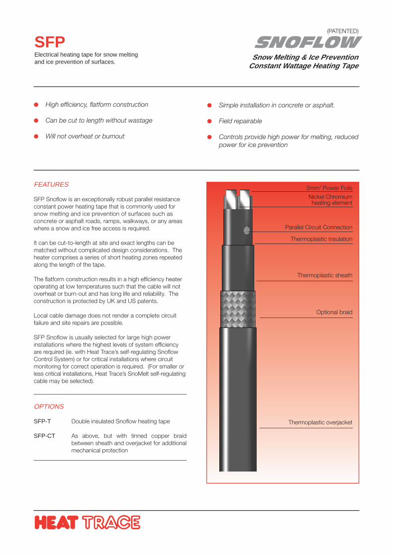
SNOFLOWSnow Melting & Ice Prevention
Constant Wattage Heating Tape
SFPElectrical heating tape for snow meltingand ice prevention of surfaces.
FEATURES
SFP Snoflow is an exceptionally robust parallel resistanceconstant power heating tape that is commonly used forsnow melting and ice prevention of surfaces such asconcrete or asphalt roads, ramps, walkways, or any areaswhere a snow and ice free access is required.
It can be cut-to-length at site and exact lengths can bematched without complicated design considerations. Theheater comprises a series of short heating zones repeatedalong the length of the tape.
The flatform construction results in a high efficiency heateroperating at low temperatures such that the cable will notoverheat or burn-out and has long life and reliability. Theconstruction is protected by UK and US patents.
Local cable damage does not render a complete circuitfailure and site repairs are possible.
SFP Snoflow is usually selected for large high powerinstallations where the highest levels of system efficiencyare required (ie. with Heat Trace’s self-regulating SnoflowControl System) or for critical installations where circuitmonitoring for correct operation is required. (For smaller orless critical installations, Heat Trace’s SnoMelt self-regulatingcable may be selected).
OPTIONS
SFP-T Double insulated Snoflow heating tape
SFP-CT As above, but with tinned copper braidbetween sheath and overjacket for additionalmechanical protection
High efficiency, flatform construction
Can be cut to length without wastage
Will not overheat or burnout
Simple installation in concrete or asphalt.
Field repairable
Controls provide high power for melting, reducedpower for ice prevention
3mm2 Power FoilsNickel Chromiumheating element
Parallel Circuit Connection
Thermoplastic insulation
Thermoplastic sheath
Optional braid
Thermoplastic overjacket
(PATENTED)
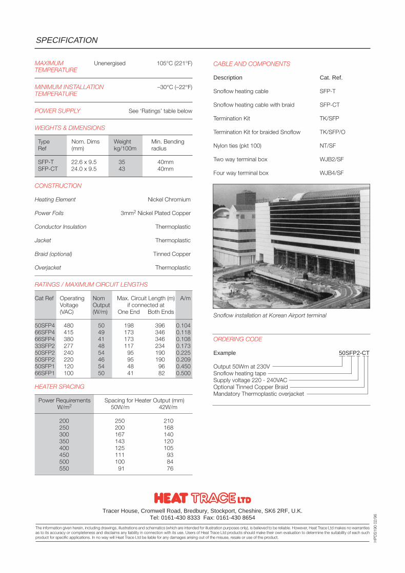
MAXIMUM Unenergised 105°C (221°F)TEMPERATURE
MINIMUM INSTALLATION –30°C (–22°F)TEMPERATURE
POWER SUPPLY See ‘Ratings’ table below
WEIGHTS & DIMENSIONS
Type Nom. Dims Weight Min. BendingRef (mm) kg/100m radius
SFP-T 22.6 x 9.5 35 40mmSFP-CT 24.0 x 9.5 43 40mm
CONSTRUCTION
Heating Element Nickel Chromium
Power Foils 3mm2 Nickel Plated Copper
Conductor Insulation Thermoplastic
Jacket Thermoplastic
Braid (optional) Tinned Copper
Overjacket Thermoplastic
RATINGS / MAXIMUM CIRCUIT LENGTHS
Cat Ref Operating Nom Max. Circuit Length (m) A/mVoltage Output if connected at(VAC) (W/m) One End Both Ends
50SFP4 480 50 198 396 0.10466SFP4 415 49 173 346 0.11866SFP4 380 41 173 346 0.10833SFP2 277 48 117 234 0.17350SFP2 240 54 95 190 0.22550SFP2 220 46 95 190 0.20950SFP1 120 54 48 96 0.45066SFP1 100 50 41 82 0.500
HEATER SPACING
Power Requirements Spacing for Heater Output (mm)W/m2 50W/m 42W/m
200 250 210250 200 168300 167 140350 143 120400 125 105450 111 93500 100 84550 91 76
SPECIFICATION
Tracer House, Cromwell Road, Bredbury, Stockport, Cheshire, SK6 2RF, U.K.Tel: 0161-430 8333 Fax: 0161-430 8654
The information given herein, including drawings, illustrations and schematics (which are intended for illustration purposes only), is believed to be reliable. However, Heat Trace Ltd makes no warrantiesas to its accuracy or completeness and disclaims any liability in connection with its use. Users of Heat Trace Ltd products should make their own evaluation to determine the suitability of each suchproduct for specific applications. In no way will Heat Trace Ltd be liable for any damages arising out of the misuse, resale or use of the product.
HP
DS
190
02/9
6
CABLE AND COMPONENTS
Description Cat. Ref.
Snoflow heating cable SFP-T
Snoflow heating cable with braid SFP-CT
Termination Kit TK/SFP
Termination Kit for braided Snoflow TK/SFP/O
Nylon ties (pkt 100) NT/SF
Two way terminal box WJB2/SF
Four way terminal box WJB4/SF
ORDERING CODE
Example 50SFP2-CT
Output 50Wm at 230VSnoflow heating tapeSupply voltage 220 - 240VACOptional Tinned Copper BraidMandatory Thermoplastic overjacket
Snoflow installation at Korean Airport terminal
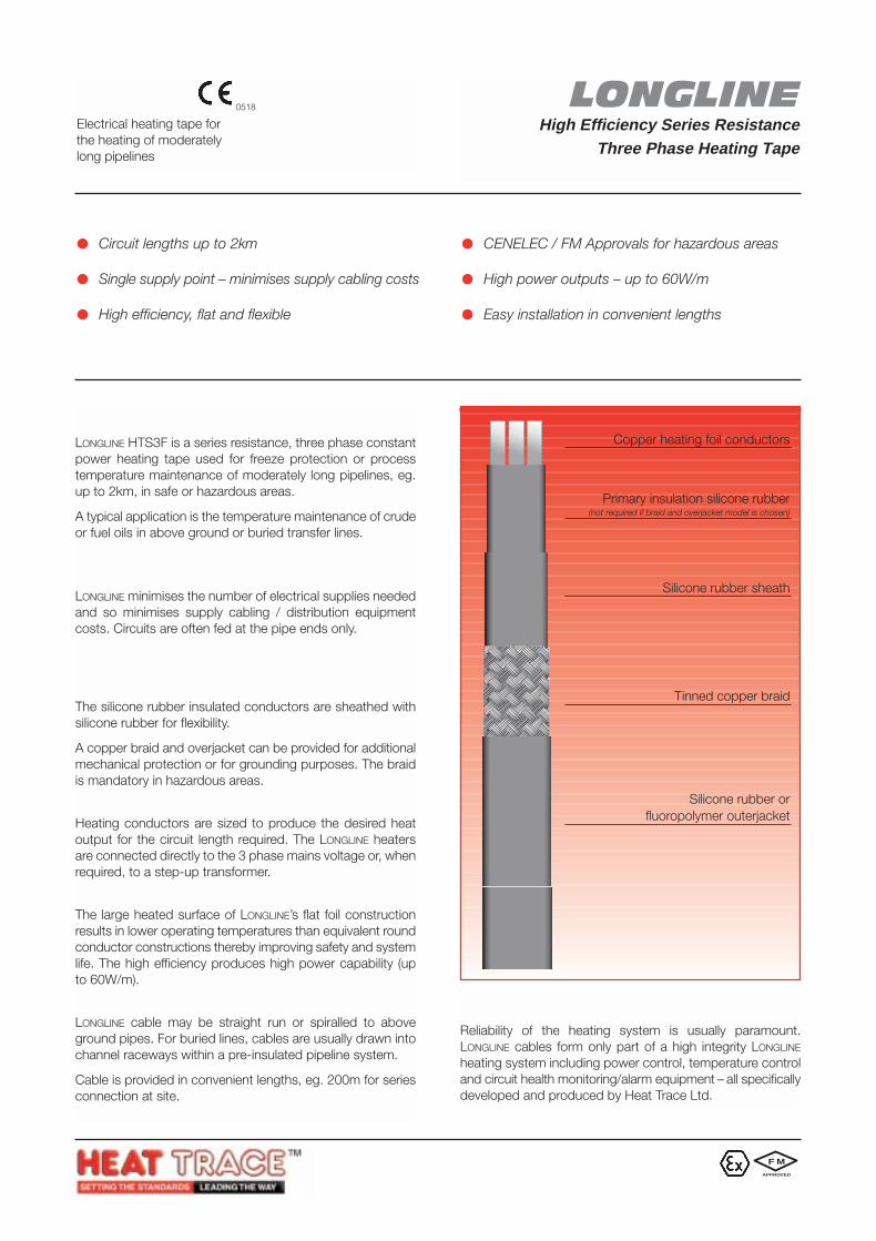
LONGLINEHigh Efficiency Series Resistance
Three Phase Heating Tape
HTS3FElectrical heating tape forthe heating of moderatelylong pipelines
APPLICATIONS
LONGLINE HTS3F is a series resistance, three phase constantpower heating tape used for freeze protection or processtemperature maintenance of moderately long pipelines, eg.up to 2km, in safe or hazardous areas.
A typical application is the temperature maintenance of crudeor fuel oils in above ground or buried transfer lines.
MINIMAL SUPPLY / DISTRIBUTION COSTS
LONGLINE minimises the number of electrical supplies neededand so minimises supply cabling / distribution equipmentcosts. Circuits are often fed at the pipe ends only.
FEATURES
ConstructionThe silicone rubber insulated conductors are sheathed withsilicone rubber for flexibility.
A copper braid and overjacket can be provided for additionalmechanical protection or for grounding purposes. The braidis mandatory in hazardous areas.
The DesignHeating conductors are sized to produce the desired heatoutput for the circuit length required. The LONGLINE heatersare connected directly to the 3 phase mains voltage or, whenrequired, to a step-up transformer.
Improved Safety and EfficiencyThe large heated surface of LONGLINE’s flat foil constructionresults in lower operating temperatures than equivalent roundconductor constructions thereby improving safety and systemlife. The high efficiency produces high power capability (upto 60W/m).
InstallationLONGLINE cable may be straight run or spiralled to aboveground pipes. For buried lines, cables are usually drawn intochannel raceways within a pre-insulated pipeline system.
Cable is provided in convenient lengths, eg. 200m for seriesconnection at site.
Circuit lengths up to 2km
Single supply point – minimises supply cabling costs
High efficiency, flat and flexible
CENELEC / FM Approvals for hazardous areas
High power outputs – up to 60W/m
Easy installation in convenient lengths
LONGLINE – A COMPLETE SYSTEM
Reliability of the heating system is usually paramount.LONGLINE cables form only part of a high integrity LONGLINE
heating system including power control, temperature controland circuit health monitoring/alarm equipment – all specificallydeveloped and produced by Heat Trace Ltd.
Copper heating foil conductors
Primary insulation silicone rubber(not required if braid and overjacket model is chosen)
Silicone rubber sheath
Tinned copper braid
Silicone rubber orfluoropolymer outerjacket
F M
APPROVED
0518
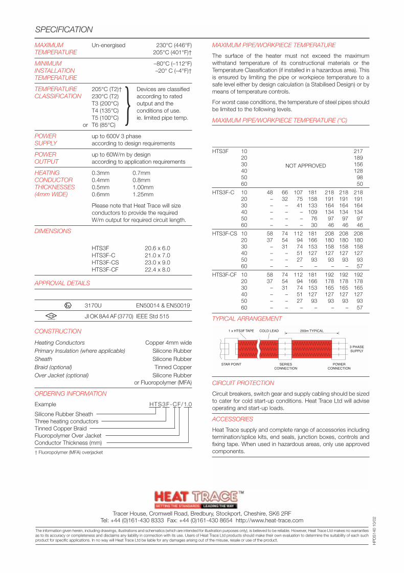
MAXIMUM Un-energised 230°C (446°F)TEMPERATURE 205°C (401°F)†
MINIMUM –80°C (–112°F)INSTALLATION –20° C (–4°F)†TEMPERATURE
TEMPERATURE 205°C (T2)† Devices are classifiedCLASSIFICATION 230°C (T2) according to rated
T3 (200°C) output and theT4 (135°C) conditions of use.T5 (100°C) ie. limited pipe temp.
or T6 (85°C)
POWER up to 600V 3 phaseSUPPLY according to design requirements
POWER up to 60W/m by designOUTPUT according to application requirements
HEATING 0.3mm 0.7mmCONDUCTOR 0.4mm 0.8mmTHICKNESSES 0.5mm 1.00mm(4mm WIDE) 0.6mm 1.25mm
Please note that Heat Trace will sizeconductors to provide the requiredW/m output for required circuit length.
DIMENSIONS Type Nom. DimsRef (mm)
HTS3F 20.6 x 6.0HTS3F-C 21.0 x 7.0HTS3F-CS 23.0 x 9.0HTS3F-CF 22.4 x 8.0
APPROVAL DETAILS
Testing Authority Certificate No. Standard
CENELEC 3170U EN50014 & EN50019
FM JI OK 8A4 AF (3770) IEEE Std 515
CONSTRUCTION
Heating Conductors Copper 4mm widePrimary Insulation (where applicable) Silicone RubberSheath Silicone RubberBraid (optional) Tinned CopperOver Jacket (optional) Silicone Rubber
or Fluoropolymer (MFA)
ORDERING INFORMATION
Example HTS3F-CF/1.0
Silicone Rubber SheathThree heating conductorsTinned Copper BraidFluoropolymer Over JacketConductor Thickness (mm)
† Fluoropolymer (MFA) overjacket
MAXIMUM PIPE/WORKPIECE TEMPERATURE
The surface of the heater must not exceed the maximumwithstand temperature of its constructional materials or theTemperature Classification (if installed in a hazardous area). Thisis ensured by limiting the pipe or workpiece temperature to asafe level either by design calculation (a Stabilised Design) or bymeans of temperature controls.
For worst case conditions, the temperature of steel pipes shouldbe limited to the following levels.
MAXIMUM PIPE/WORKPIECE TEMPERATURE (°C)
Cat Ref Nom. Area ClassificationOutput Hazardous Safe(W/m) T6 T5 T4 T3 T2 T1
HTS3F 10 21720 18930 15640 12850 9860 50
HTS3F-C 10 48 66 107 181 218 218 21820 – 32 75 158 191 191 19130 – – 41 133 164 164 16440 – – – 109 134 134 13450 – – – 76 97 97 9760 – – – 30 46 46 46
HTS3F-CS 10 58 74 112 181 208 208 20820 37 54 94 166 180 180 18030 – 31 74 153 158 158 15840 – – 51 127 127 127 12750 – – 27 93 93 93 9360 – – – – – – 57
HTS3F-CF 10 58 74 112 181 192 192 19220 37 54 94 166 178 178 17830 – 31 74 153 165 165 16540 – – 51 127 127 127 12750 – – 27 93 93 93 9360 – – – – – – 57
TYPICAL ARRANGEMENT
SPECIFICATION
HP
DS
140
10/0
2
200m TYPICAL1 x HTS3F TAPE
STAR POINT SERIESCONNECTION
POWERCONNECTION
3 PHASESUPPLY
COLD LEAD
CIRCUIT PROTECTION
Circuit breakers, switch gear and supply cabling should be sizedto cater for cold start-up conditions. Heat Trace Ltd will adviseoperating and start-up loads.
ACCESSORIES
Heat Trace supply and complete range of accessories includingtermination/splice kits, end seals, junction boxes, controls andfixing tape. When used in hazardous areas, only use approvedcomponents.
NOT APPROVED
Tracer House, Cromwell Road, Bredbury, Stockport, Cheshire, SK6 2RFTel: +44 (0)161-430 8333 Fax: +44 (0)161-430 8654 http://www.heat-trace.com
The information given herein, including drawings, illustrations and schematics (which are intended for illustration purposes only), is believed to be reliable. However, Heat Trace Ltd makes no warrantiesas to its accuracy or completeness and disclaims any liability in connection with its use. Users of Heat Trace Ltd products should make their own evaluation to determine the suitability of each suchproduct for specific applications. In no way will Heat Trace Ltd be liable for any damages arising out of the misuse, resale or use of the product.
F M
APPROVED
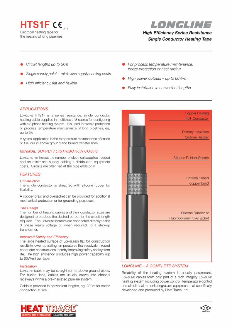
LONGLINEHigh Efficiency Series Resistance
Single Conductor Heating Tape
HTS1FElectrical heating tape forthe heating of long pipelines
APPLICATIONSLONGLINE HTS1F is a series resistance, single conductorheating cable supplied in multiples of 3 cables for configuringwith a 3 phase heating system. It is used for freeze protectionor process temperature maintenance of long pipelines, eg.up to 5km.
A typical application is the temperature maintenance of crudeor fuel oils in above ground and buried transfer lines.
MINIMAL SUPPLY / DISTRIBUTION COSTSLONGLINE minimises the number of electrical supplies neededand so minimises supply cabling / distribution equipmentcosts. Circuits are often fed at the pipe ends only.
FEATURES
ConstructionThe single conductor is sheathed with silicone rubber forflexibility.
A copper braid and overjacket can be provided for additionalmechanical protection or for grounding purposes.
The DesignThe number of heating cables and their conductor sizes aredesigned to produce the desired output for the circuit lengthrequired. The LONGLINE heaters are connected directly to the3 phase mains voltage or, when required, to a step-uptransformer.
Improved Safety and EfficiencyThe large heated surface of LONGLINE’s flat foil constructionresults in lower operating temperatures than equivalent roundconductor constructions thereby improving safety and systemlife. The high efficiency produces high power capability (upto 60W/m) per tape.
InstallationLONGLINE cable may be straight run to above ground pipes.For buried lines, cables are usually drawn into channelraceways within a pre-insulated pipeline system.
Cable is provided in convenient lengths, eg. 200m for seriesconnection at site.
Circuit lengths up to 5km
Single supply point – minimises supply cabling costs
High efficiency, flat and flexible
For process temperature maintenance,freeze protection or heat raising
High power outputs – up to 60W/m
Easy installation in convenient lengths
LONGLINE – A COMPLETE SYSTEM
Reliability of the heating system is usually paramount.LONGLINE cables form only part of a high integrity LONGLINE
heating system including power control, temperature controland circuit health monitoring/alarm equipment – all specificallydeveloped and produced by Heat Trace Ltd.
Copper Heating
Foil Conductor
Primary Insulation
Silicone Rubber
Silicone Rubber Sheath
Optional tinned
copper braid
Silicone Rubber or
Fluoropolymer Over jacket
0518
F M
APPROVED
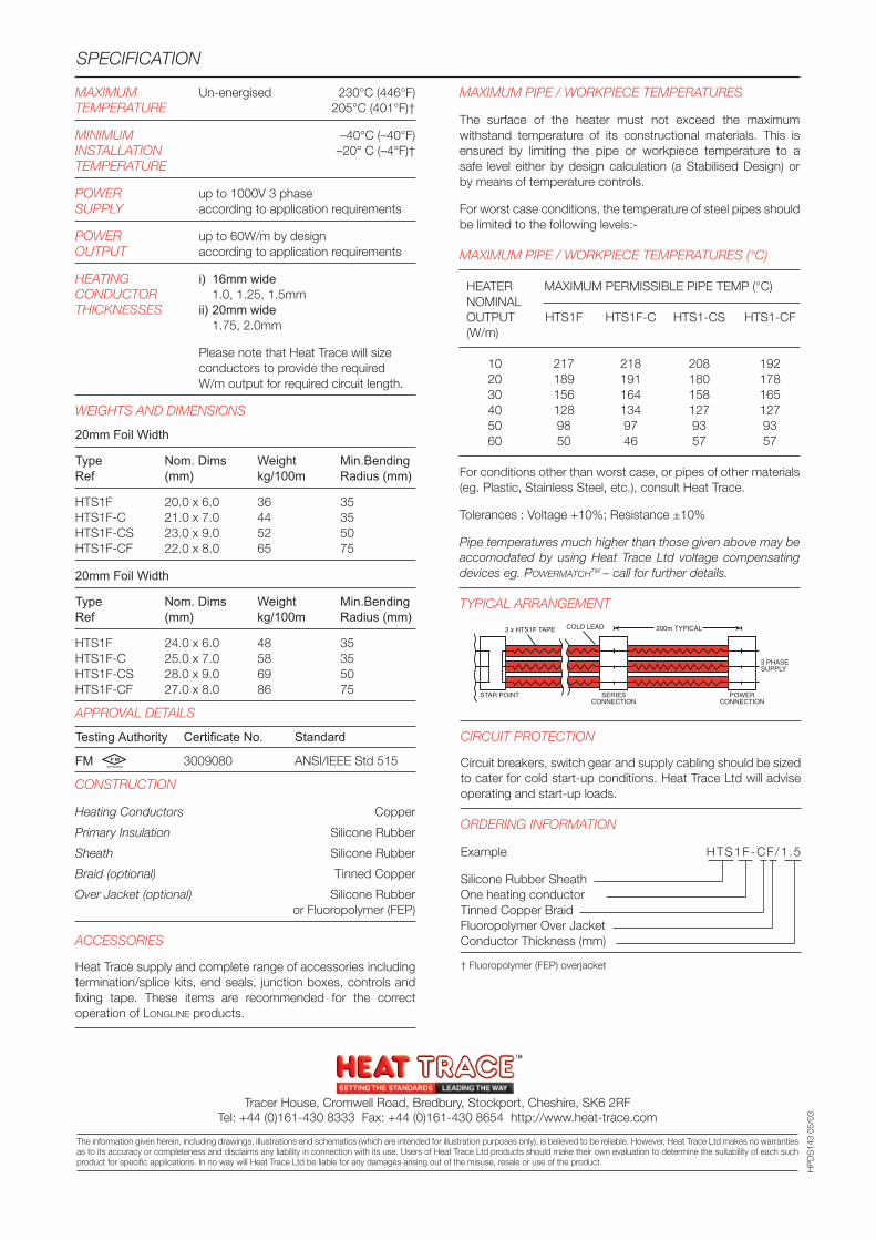
MAXIMUM Un-energised 230°C (446°F)TEMPERATURE 205°C (401°F)†
MINIMUM –40°C (–40°F)INSTALLATION –20° C (–4°F)†TEMPERATURE
POWER up to 1000V 3 phaseSUPPLY according to application requirements
POWER up to 60W/m by designOUTPUT according to application requirements
HEATING i) 16mm wideCONDUCTOR 1.0, 1.25, 1.5mmTHICKNESSES ii) 20mm wide
1.75, 2.0mm
Please note that Heat Trace will sizeconductors to provide the requiredW/m output for required circuit length.
WEIGHTS AND DIMENSIONS
20mm Foil Width
Type Nom. Dims Weight Min.BendingRef (mm) kg/100m Radius (mm)
HTS1F 20.0 x 6.0 36 35HTS1F-C 21.0 x 7.0 44 35HTS1F-CS 23.0 x 9.0 52 50HTS1F-CF 22.0 x 8.0 65 75
20mm Foil Width
Type Nom. Dims Weight Min.BendingRef (mm) kg/100m Radius (mm)
HTS1F 24.0 x 6.0 48 35HTS1F-C 25.0 x 7.0 58 35HTS1F-CS 28.0 x 9.0 69 50HTS1F-CF 27.0 x 8.0 86 75
APPROVAL DETAILS
Testing Authority Certificate No. Standard
FM 3009080 ANSI/IEEE Std 515
CONSTRUCTION
Heating Conductors Copper
Primary Insulation Silicone Rubber
Sheath Silicone Rubber
Braid (optional) Tinned Copper
Over Jacket (optional) Silicone Rubberor Fluoropolymer (FEP)
ACCESSORIES
Heat Trace supply and complete range of accessories includingtermination/splice kits, end seals, junction boxes, controls andfixing tape. These items are recommended for the correctoperation of LONGLINE products.
MAXIMUM PIPE / WORKPIECE TEMPERATURES
The surface of the heater must not exceed the maximumwithstand temperature of its constructional materials. This isensured by limiting the pipe or workpiece temperature to asafe level either by design calculation (a Stabilised Design) orby means of temperature controls.
For worst case conditions, the temperature of steel pipes shouldbe limited to the following levels:-
MAXIMUM PIPE / WORKPIECE TEMPERATURES (°C)
HEATER MAXIMUM PERMISSIBLE PIPE TEMP (°C)NOMINALOUTPUT HTS1F HTS1F-C HTS1-CS HTS1-CF(W/m)
10 217 218 208 19220 189 191 180 17830 156 164 158 16540 128 134 127 12750 98 97 93 9360 50 46 57 57
For conditions other than worst case, or pipes of other materials(eg. Plastic, Stainless Steel, etc.), consult Heat Trace.
Tolerances : Voltage +10%; Resistance ±10%
Pipe temperatures much higher than those given above may beaccomodated by using Heat Trace Ltd voltage compensatingdevices eg. POWERMATCHTM – call for further details.
TYPICAL ARRANGEMENT
SPECIFICATION
The information given herein, including drawings, illustrations and schematics (which are intended for illustration purposes only), is believed to be reliable. However, Heat Trace Ltd makes no warrantiesas to its accuracy or completeness and disclaims any liability in connection with its use. Users of Heat Trace Ltd products should make their own evaluation to determine the suitability of each suchproduct for specific applications. In no way will Heat Trace Ltd be liable for any damages arising out of the misuse, resale or use of the product.
HP
DS
143
05/0
3
STAR POINT SERIESCONNECTION
POWERCONNECTION
3 PHASESUPPLY
200m TYPICALCOLD LEAD3 x HTS1F TAPE
CIRCUIT PROTECTION
Circuit breakers, switch gear and supply cabling should be sizedto cater for cold start-up conditions. Heat Trace Ltd will adviseoperating and start-up loads.
ORDERING INFORMATION
Example HTS1F-CF/1.5
Silicone Rubber SheathOne heating conductorTinned Copper BraidFluoropolymer Over JacketConductor Thickness (mm)
† Fluoropolymer (FEP) overjacket
Tracer House, Cromwell Road, Bredbury, Stockport, Cheshire, SK6 2RFTel: +44 (0)161-430 8333 Fax: +44 (0)161-430 8654 http://www.heat-trace.com
F M
APPROVED
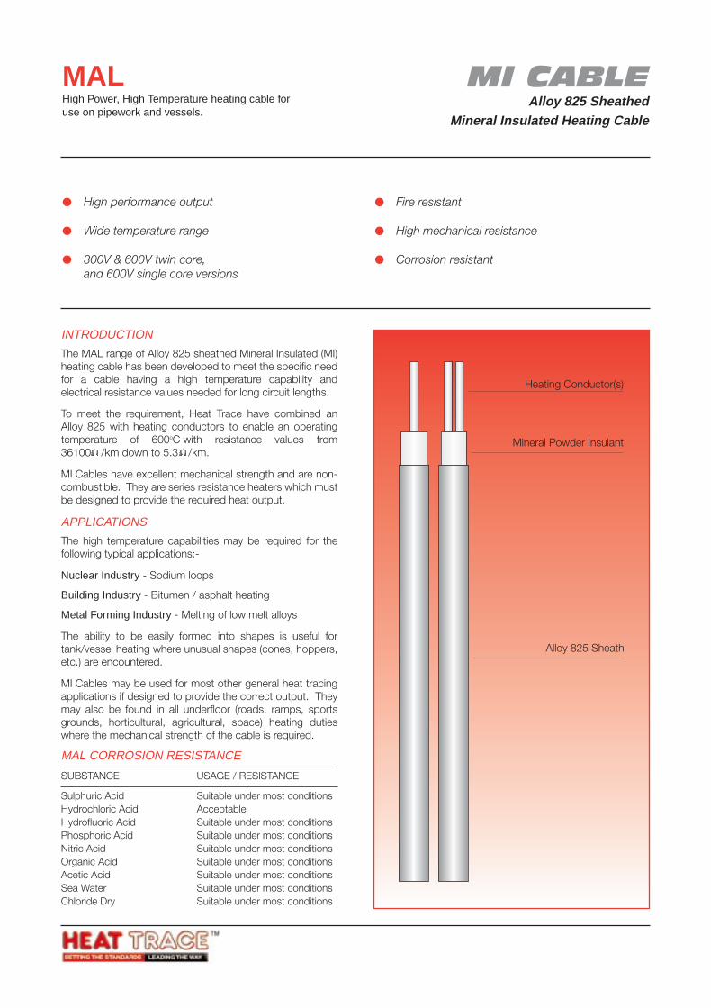
MI CABLEAlloy 825 Sheathed
Mineral Insulated Heating Cable
MALHigh Power, High Temperature heating cable foruse on pipework and vessels.
INTRODUCTION
The MAL range of Alloy 825 sheathed Mineral Insulated (MI)heating cable has been developed to meet the specific needfor a cable having a high temperature capability andelectrical resistance values needed for long circuit lengths.
To meet the requirement, Heat Trace have combined anAlloy 825 with heating conductors to enable an operatingtemperature of 600oC with resistance values from36100 /km down to 5.3 /km.
MI Cables have excellent mechanical strength and are non-combustible. They are series resistance heaters which mustbe designed to provide the required heat output.
APPLICATIONS
The high temperature capabilities may be required for thefollowing typical applications:-
Nuclear Industry - Sodium loops
Building Industry - Bitumen / asphalt heating
Metal Forming Industry - Melting of low melt alloys
The ability to be easily formed into shapes is useful fortank/vessel heating where unusual shapes (cones, hoppers,etc.) are encountered.
MI Cables may be used for most other general heat tracingapplications if designed to provide the correct output. Theymay also be found in all underfloor (roads, ramps, sportsgrounds, horticultural, agricultural, space) heating dutieswhere the mechanical strength of the cable is required.
MAL CORROSION RESISTANCE
SUBSTANCE USAGE / RESISTANCE
Sulphuric Acid Suitable under most conditionsHydrochloric Acid AcceptableHydrofluoric Acid Suitable under most conditionsPhosphoric Acid Suitable under most conditionsNitric Acid Suitable under most conditionsOrganic Acid Suitable under most conditionsAcetic Acid Suitable under most conditionsSea Water Suitable under most conditionsChloride Dry Suitable under most conditions
High performance output
Wide temperature range
300V & 600V twin core,and 600V single core versions
Fire resistant
High mechanical resistance
Corrosion resistant
Mineral Powder Insulant
Heating Conductor(s)
Alloy 825 Sheath
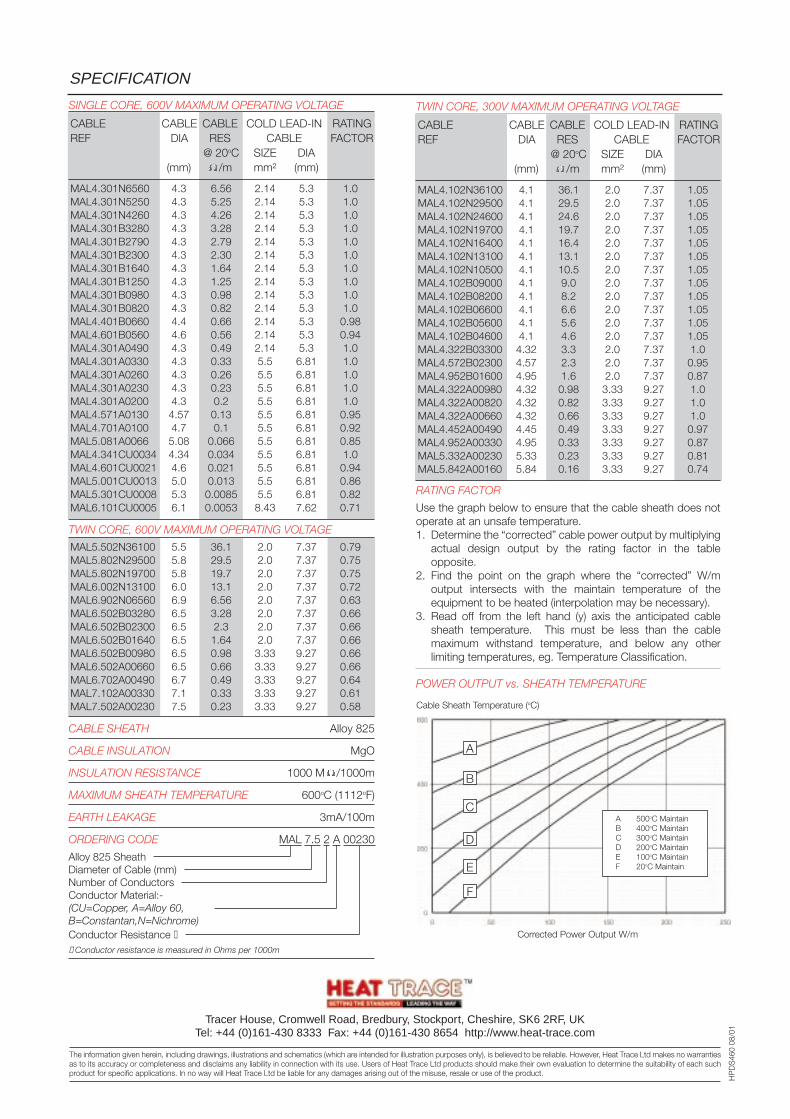
TWIN CORE, 300V MAXIMUM OPERATING VOLTAGE
CABLE CABLE CABLE COLD LEAD-IN RATINGREF DIA RES CABLE FACTOR
@ 20oC SIZE DIA(mm) /m mm² (mm)
MAL4.102N36100 4.1 36.1 2.0 7.37 1.05MAL4.102N29500 4.1 29.5 2.0 7.37 1.05MAL4.102N24600 4.1 24.6 2.0 7.37 1.05MAL4.102N19700 4.1 19.7 2.0 7.37 1.05MAL4.102N16400 4.1 16.4 2.0 7.37 1.05MAL4.102N13100 4.1 13.1 2.0 7.37 1.05MAL4.102N10500 4.1 10.5 2.0 7.37 1.05MAL4.102B09000 4.1 9.0 2.0 7.37 1.05MAL4.102B08200 4.1 8.2 2.0 7.37 1.05MAL4.102B06600 4.1 6.6 2.0 7.37 1.05MAL4.102B05600 4.1 5.6 2.0 7.37 1.05MAL4.102B04600 4.1 4.6 2.0 7.37 1.05MAL4.322B03300 4.32 3.3 2.0 7.37 1.0MAL4.572B02300 4.57 2.3 2.0 7.37 0.95MAL4.952B01600 4.95 1.6 2.0 7.37 0.87MAL4.322A00980 4.32 0.98 3.33 9.27 1.0MAL4.322A00820 4.32 0.82 3.33 9.27 1.0MAL4.322A00660 4.32 0.66 3.33 9.27 1.0MAL4.452A00490 4.45 0.49 3.33 9.27 0.97MAL4.952A00330 4.95 0.33 3.33 9.27 0.87MAL5.332A00230 5.33 0.23 3.33 9.27 0.81MAL5.842A00160 5.84 0.16 3.33 9.27 0.74
RATING FACTOR
Use the graph below to ensure that the cable sheath does notoperate at an unsafe temperature.1. Determine the “corrected” cable power output by multiplying
actual design output by the rating factor in the tableopposite.
2. Find the point on the graph where the “corrected” W/moutput intersects with the maintain temperature of theequipment to be heated (interpolation may be necessary).
3. Read off from the left hand (y) axis the anticipated cablesheath temperature. This must be less than the cablemaximum withstand temperature, and below any otherlimiting temperatures, eg. Temperature Classification.
POWER OUTPUT vs. SHEATH TEMPERATURE
SPECIFICATION
Tracer House, Cromwell Road, Bredbury, Stockport, Cheshire, SK6 2RF, UKTel: +44 (0)161-430 8333 Fax: +44 (0)161-430 8654 http://www.heat-trace.com
The information given herein, including drawings, illustrations and schematics (which are intended for illustration purposes only), is believed to be reliable. However, Heat Trace Ltd makes no warrantiesas to its accuracy or completeness and disclaims any liability in connection with its use. Users of Heat Trace Ltd products should make their own evaluation to determine the suitability of each suchproduct for specific applications. In no way will Heat Trace Ltd be liable for any damages arising out of the misuse, resale or use of the product.
HP
DS
460
08/0
1
SINGLE CORE, 600V MAXIMUM OPERATING VOLTAGE
CABLE CABLE CABLE COLD LEAD-IN RATINGREF DIA RES CABLE FACTOR
@ 20oC SIZE DIA(mm) /m mm² (mm)
MAL4.301N6560 4.3 6.56 2.14 5.3 1.0MAL4.301N5250 4.3 5.25 2.14 5.3 1.0MAL4.301N4260 4.3 4.26 2.14 5.3 1.0MAL4.301B3280 4.3 3.28 2.14 5.3 1.0MAL4.301B2790 4.3 2.79 2.14 5.3 1.0MAL4.301B2300 4.3 2.30 2.14 5.3 1.0MAL4.301B1640 4.3 1.64 2.14 5.3 1.0MAL4.301B1250 4.3 1.25 2.14 5.3 1.0MAL4.301B0980 4.3 0.98 2.14 5.3 1.0MAL4.301B0820 4.3 0.82 2.14 5.3 1.0MAL4.401B0660 4.4 0.66 2.14 5.3 0.98MAL4.601B0560 4.6 0.56 2.14 5.3 0.94MAL4.301A0490 4.3 0.49 2.14 5.3 1.0MAL4.301A0330 4.3 0.33 5.5 6.81 1.0MAL4.301A0260 4.3 0.26 5.5 6.81 1.0MAL4.301A0230 4.3 0.23 5.5 6.81 1.0MAL4.301A0200 4.3 0.2 5.5 6.81 1.0MAL4.571A0130 4.57 0.13 5.5 6.81 0.95MAL4.701A0100 4.7 0.1 5.5 6.81 0.92MAL5.081A0066 5.08 0.066 5.5 6.81 0.85MAL4.341CU0034 4.34 0.034 5.5 6.81 1.0MAL4.601CU0021 4.6 0.021 5.5 6.81 0.94MAL5.001CU0013 5.0 0.013 5.5 6.81 0.86MAL5.301CU0008 5.3 0.0085 5.5 6.81 0.82MAL6.101CU0005 6.1 0.0053 8.43 7.62 0.71
TWIN CORE, 600V MAXIMUM OPERATING VOLTAGE
MAL5.502N36100 5.5 36.1 2.0 7.37 0.79MAL5.802N29500 5.8 29.5 2.0 7.37 0.75MAL5.802N19700 5.8 19.7 2.0 7.37 0.75MAL6.002N13100 6.0 13.1 2.0 7.37 0.72MAL6.902N06560 6.9 6.56 2.0 7.37 0.63MAL6.502B03280 6.5 3.28 2.0 7.37 0.66MAL6.502B02300 6.5 2.3 2.0 7.37 0.66MAL6.502B01640 6.5 1.64 2.0 7.37 0.66MAL6.502B00980 6.5 0.98 3.33 9.27 0.66MAL6.502A00660 6.5 0.66 3.33 9.27 0.66MAL6.702A00490 6.7 0.49 3.33 9.27 0.64MAL7.102A00330 7.1 0.33 3.33 9.27 0.61MAL7.502A00230 7.5 0.23 3.33 9.27 0.58
CABLE SHEATH Alloy 825
CABLE INSULATION MgO
INSULATION RESISTANCE 1000 M /1000m
MAXIMUM SHEATH TEMPERATURE 600oC (1112oF)
EARTH LEAKAGE 3mA/100m
ORDERING CODE MAL 7.5 2 A 00230
Alloy 825 SheathDiameter of Cable (mm)Number of ConductorsConductor Material:-(CU=Copper, A=Alloy 60,B=Constantan,N=Nichrome)Conductor Resistance Conductor resistance is measured in Ohms per 1000m
Corrected Power Output W/m
Cable Sheath Temperature (oC)
A
B
C
D
E
F
A 500oC MaintainB 400oC MaintainC 300oC MaintainD 200oC MaintainE 100oC MaintainF 20oC Maintain
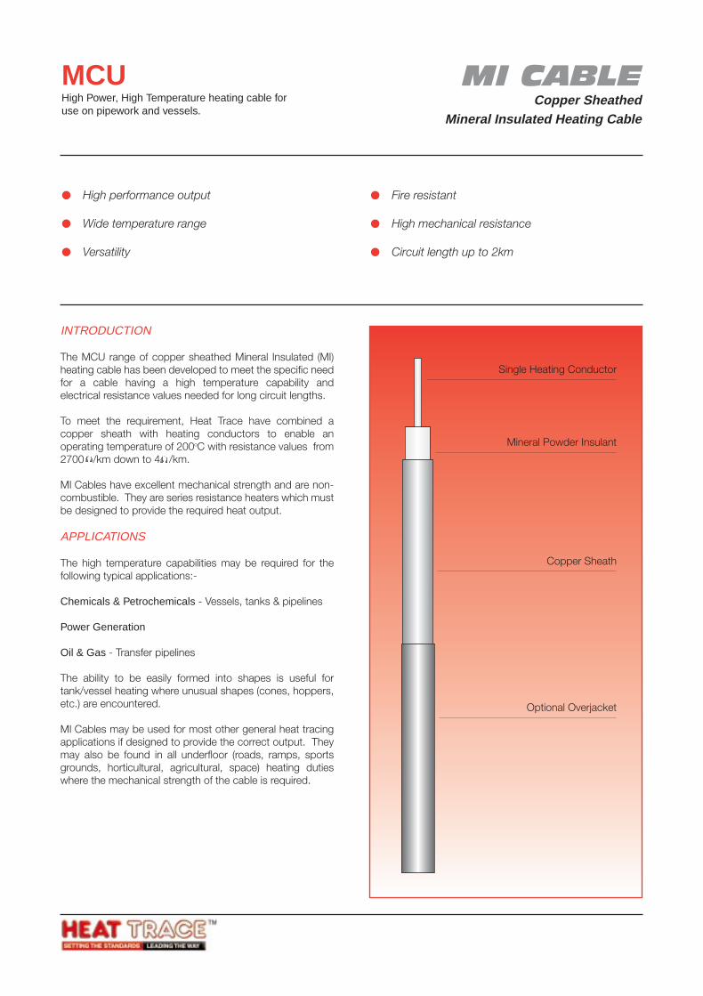
MI CABLECopper Sheathed
Mineral Insulated Heating Cable
MCUHigh Power, High Temperature heating cable foruse on pipework and vessels.
INTRODUCTION
The MCU range of copper sheathed Mineral Insulated (MI)heating cable has been developed to meet the specific needfor a cable having a high temperature capability andelectrical resistance values needed for long circuit lengths.
To meet the requirement, Heat Trace have combined acopper sheath with heating conductors to enable anoperating temperature of 200oC with resistance values from2700 /km down to 4 /km.
MI Cables have excellent mechanical strength and are non-combustible. They are series resistance heaters which mustbe designed to provide the required heat output.
APPLICATIONS
The high temperature capabilities may be required for thefollowing typical applications:-
Chemicals & Petrochemicals - Vessels, tanks & pipelines
Power Generation
Oil & Gas - Transfer pipelines
The ability to be easily formed into shapes is useful fortank/vessel heating where unusual shapes (cones, hoppers,etc.) are encountered.
MI Cables may be used for most other general heat tracingapplications if designed to provide the correct output. Theymay also be found in all underfloor (roads, ramps, sportsgrounds, horticultural, agricultural, space) heating dutieswhere the mechanical strength of the cable is required.
High performance output
Wide temperature range
Versatility
Fire resistant
High mechanical resistance
Circuit length up to 2km
Mineral Powder Insulant
Single Heating Conductor
Copper Sheath
Optional Overjacket
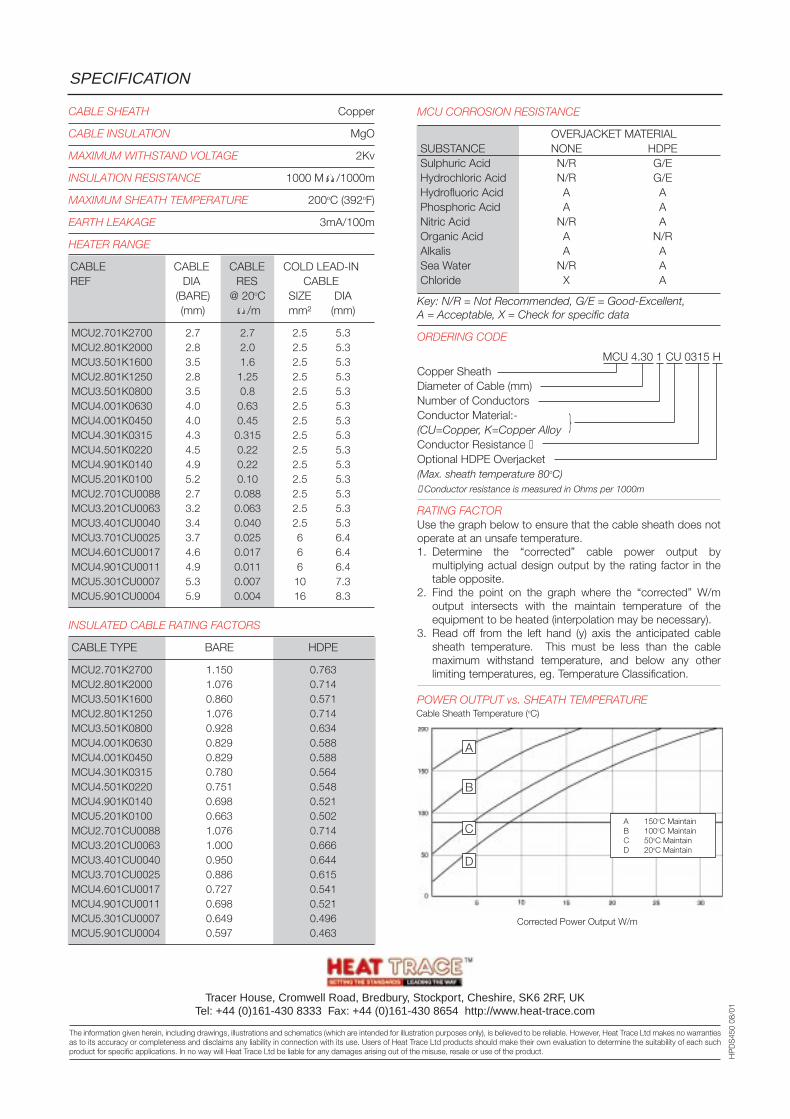
MCU CORROSION RESISTANCE
OVERJACKET MATERIALSUBSTANCE NONE HDPESulphuric Acid N/R G/EHydrochloric Acid N/R G/EHydrofluoric Acid A APhosphoric Acid A ANitric Acid N/R AOrganic Acid A N/RAlkalis A ASea Water N/R AChloride X A
Key: N/R = Not Recommended, G/E = Good-Excellent,A = Acceptable, X = Check for specific data
ORDERING CODE
MCU 4.30 1 CU 0315 HCopper SheathDiameter of Cable (mm)Number of ConductorsConductor Material:-(CU=Copper, K=Copper AlloyConductor Resistance Optional HDPE Overjacket(Max. sheath temperature 80oC) Conductor resistance is measured in Ohms per 1000m
RATING FACTORUse the graph below to ensure that the cable sheath does notoperate at an unsafe temperature.1. Determine the “corrected” cable power output by
multiplying actual design output by the rating factor in thetable opposite.
2. Find the point on the graph where the “corrected” W/moutput intersects with the maintain temperature of theequipment to be heated (interpolation may be necessary).
3. Read off from the left hand (y) axis the anticipated cablesheath temperature. This must be less than the cablemaximum withstand temperature, and below any otherlimiting temperatures, eg. Temperature Classification.
POWER OUTPUT vs. SHEATH TEMPERATURE
SPECIFICATION
Tracer House, Cromwell Road, Bredbury, Stockport, Cheshire, SK6 2RF, UKTel: +44 (0)161-430 8333 Fax: +44 (0)161-430 8654 http://www.heat-trace.com
The information given herein, including drawings, illustrations and schematics (which are intended for illustration purposes only), is believed to be reliable. However, Heat Trace Ltd makes no warrantiesas to its accuracy or completeness and disclaims any liability in connection with its use. Users of Heat Trace Ltd products should make their own evaluation to determine the suitability of each suchproduct for specific applications. In no way will Heat Trace Ltd be liable for any damages arising out of the misuse, resale or use of the product.
HP
DS
450
08/0
1
CABLE SHEATH Copper
CABLE INSULATION MgO
MAXIMUM WITHSTAND VOLTAGE 2Kv
INSULATION RESISTANCE 1000 M /1000m
MAXIMUM SHEATH TEMPERATURE 200oC (392oF)
EARTH LEAKAGE 3mA/100m
HEATER RANGE
CABLE CABLE CABLE COLD LEAD-INREF DIA RES CABLE
(BARE) @ 20oC SIZE DIA(mm) /m mm² (mm)
MCU2.701K2700 2.7 2.7 2.5 5.3MCU2.801K2000 2.8 2.0 2.5 5.3MCU3.501K1600 3.5 1.6 2.5 5.3MCU2.801K1250 2.8 1.25 2.5 5.3MCU3.501K0800 3.5 0.8 2.5 5.3MCU4.001K0630 4.0 0.63 2.5 5.3MCU4.001K0450 4.0 0.45 2.5 5.3MCU4.301K0315 4.3 0.315 2.5 5.3MCU4.501K0220 4.5 0.22 2.5 5.3MCU4.901K0140 4.9 0.22 2.5 5.3MCU5.201K0100 5.2 0.10 2.5 5.3MCU2.701CU0088 2.7 0.088 2.5 5.3MCU3.201CU0063 3.2 0.063 2.5 5.3MCU3.401CU0040 3.4 0.040 2.5 5.3MCU3.701CU0025 3.7 0.025 6 6.4MCU4.601CU0017 4.6 0.017 6 6.4MCU4.901CU0011 4.9 0.011 6 6.4MCU5.301CU0007 5.3 0.007 10 7.3MCU5.901CU0004 5.9 0.004 16 8.3
INSULATED CABLE RATING FACTORS
CABLE TYPE BARE HDPE
MCU2.701K2700 1.150 0.763MCU2.801K2000 1.076 0.714MCU3.501K1600 0.860 0.571MCU2.801K1250 1.076 0.714MCU3.501K0800 0.928 0.634MCU4.001K0630 0.829 0.588MCU4.001K0450 0.829 0.588MCU4.301K0315 0.780 0.564MCU4.501K0220 0.751 0.548MCU4.901K0140 0.698 0.521MCU5.201K0100 0.663 0.502MCU2.701CU0088 1.076 0.714MCU3.201CU0063 1.000 0.666MCU3.401CU0040 0.950 0.644MCU3.701CU0025 0.886 0.615MCU4.601CU0017 0.727 0.541MCU4.901CU0011 0.698 0.521MCU5.301CU0007 0.649 0.496MCU5.901CU0004 0.597 0.463
Corrected Power Output W/m
Cable Sheath Temperature (oC)
A 150oC MaintainB 100oC MaintainC 50oC MaintainD 20oC Maintain
A
B
C
D
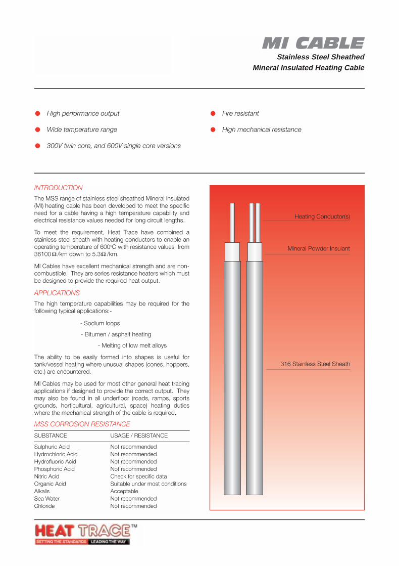
MI CABLEStainless Steel Sheathed
Mineral Insulated Heating Cable
MSSHigh Power, High Temperature heating cable foruse on pipework and vessels.
INTRODUCTION
The MSS range of stainless steel sheathed Mineral Insulated(MI) heating cable has been developed to meet the specificneed for a cable having a high temperature capability andelectrical resistance values needed for long circuit lengths.
To meet the requirement, Heat Trace have combined astainless steel sheath with heating conductors to enable anoperating temperature of 600oC with resistance values from36100 /km down to 5.3 /km.
MI Cables have excellent mechanical strength and are non-combustible. They are series resistance heaters which mustbe designed to provide the required heat output.
APPLICATIONS
The high temperature capabilities may be required for thefollowing typical applications:-
Nuclear Industry - Sodium loops
Building Industry - Bitumen / asphalt heating
Metal Forming Industry - Melting of low melt alloys
The ability to be easily formed into shapes is useful fortank/vessel heating where unusual shapes (cones, hoppers,etc.) are encountered.
MI Cables may be used for most other general heat tracingapplications if designed to provide the correct output. Theymay also be found in all underfloor (roads, ramps, sportsgrounds, horticultural, agricultural, space) heating dutieswhere the mechanical strength of the cable is required.
MSS CORROSION RESISTANCE
SUBSTANCE USAGE / RESISTANCE
Sulphuric Acid Not recommendedHydrochloric Acid Not recommendedHydrofluoric Acid Not recommendedPhosphoric Acid Not recommendedNitric Acid Check for specific dataOrganic Acid Suitable under most conditionsAlkalis AcceptableSea Water Not recommendedChloride Not recommended
High performance output
Wide temperature range
300V twin core, and 600V single core versions
Fire resistant
High mechanical resistance
Mineral Powder Insulant
Heating Conductor(s)
316 Stainless Steel Sheath
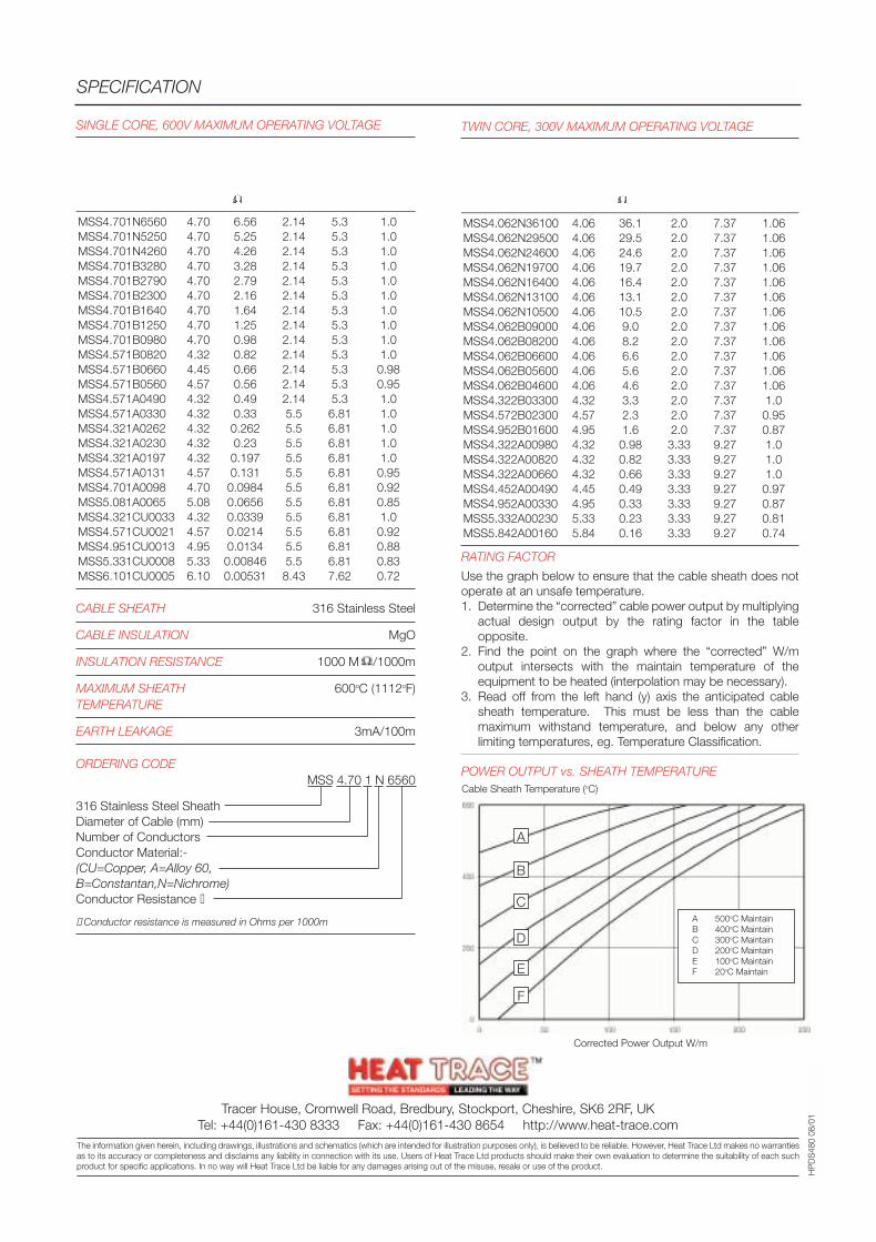
TWIN CORE, 300V MAXIMUM OPERATING VOLTAGE
Cable Cable Cable Cold Lead-in RatingReference Dia Res Cable Factor
@ 20oC Size Dia(mm) /m mm² (mm)
MSS4.062N36100 4.06 36.1 2.0 7.37 1.06MSS4.062N29500 4.06 29.5 2.0 7.37 1.06MSS4.062N24600 4.06 24.6 2.0 7.37 1.06MSS4.062N19700 4.06 19.7 2.0 7.37 1.06MSS4.062N16400 4.06 16.4 2.0 7.37 1.06MSS4.062N13100 4.06 13.1 2.0 7.37 1.06MSS4.062N10500 4.06 10.5 2.0 7.37 1.06MSS4.062B09000 4.06 9.0 2.0 7.37 1.06MSS4.062B08200 4.06 8.2 2.0 7.37 1.06MSS4.062B06600 4.06 6.6 2.0 7.37 1.06MSS4.062B05600 4.06 5.6 2.0 7.37 1.06MSS4.062B04600 4.06 4.6 2.0 7.37 1.06MSS4.322B03300 4.32 3.3 2.0 7.37 1.0MSS4.572B02300 4.57 2.3 2.0 7.37 0.95MSS4.952B01600 4.95 1.6 2.0 7.37 0.87MSS4.322A00980 4.32 0.98 3.33 9.27 1.0MSS4.322A00820 4.32 0.82 3.33 9.27 1.0MSS4.322A00660 4.32 0.66 3.33 9.27 1.0MSS4.452A00490 4.45 0.49 3.33 9.27 0.97MSS4.952A00330 4.95 0.33 3.33 9.27 0.87MSS5.332A00230 5.33 0.23 3.33 9.27 0.81MSS5.842A00160 5.84 0.16 3.33 9.27 0.74
RATING FACTOR
Use the graph below to ensure that the cable sheath does notoperate at an unsafe temperature.1. Determine the “corrected” cable power output by multiplying
actual design output by the rating factor in the tableopposite.
2. Find the point on the graph where the “corrected” W/moutput intersects with the maintain temperature of theequipment to be heated (interpolation may be necessary).
3. Read off from the left hand (y) axis the anticipated cablesheath temperature. This must be less than the cablemaximum withstand temperature, and below any otherlimiting temperatures, eg. Temperature Classification.
POWER OUTPUT vs. SHEATH TEMPERATURE
SPECIFICATION
HP
DS
480
08/0
1
SINGLE CORE, 600V MAXIMUM OPERATING VOLTAGE
Cable Cable Cable Cold Lead-in RatingReference Dia Res Cable Factor
@ 20oC Size Dia(mm) /m mm² (mm)
MSS4.701N6560 4.70 6.56 2.14 5.3 1.0MSS4.701N5250 4.70 5.25 2.14 5.3 1.0MSS4.701N4260 4.70 4.26 2.14 5.3 1.0MSS4.701B3280 4.70 3.28 2.14 5.3 1.0MSS4.701B2790 4.70 2.79 2.14 5.3 1.0MSS4.701B2300 4.70 2.16 2.14 5.3 1.0MSS4.701B1640 4.70 1.64 2.14 5.3 1.0MSS4.701B1250 4.70 1.25 2.14 5.3 1.0MSS4.701B0980 4.70 0.98 2.14 5.3 1.0MSS4.571B0820 4.32 0.82 2.14 5.3 1.0MSS4.571B0660 4.45 0.66 2.14 5.3 0.98MSS4.571B0560 4.57 0.56 2.14 5.3 0.95MSS4.571A0490 4.32 0.49 2.14 5.3 1.0MSS4.571A0330 4.32 0.33 5.5 6.81 1.0MSS4.321A0262 4.32 0.262 5.5 6.81 1.0MSS4.321A0230 4.32 0.23 5.5 6.81 1.0MSS4.321A0197 4.32 0.197 5.5 6.81 1.0MSS4.571A0131 4.57 0.131 5.5 6.81 0.95MSS4.701A0098 4.70 0.0984 5.5 6.81 0.92MSS5.081A0065 5.08 0.0656 5.5 6.81 0.85MSS4.321CU0033 4.32 0.0339 5.5 6.81 1.0MSS4.571CU0021 4.57 0.0214 5.5 6.81 0.92MSS4.951CU0013 4.95 0.0134 5.5 6.81 0.88MSS5.331CU0008 5.33 0.00846 5.5 6.81 0.83MSS6.101CU0005 6.10 0.00531 8.43 7.62 0.72
CABLE SHEATH 316 Stainless Steel
CABLE INSULATION MgO
INSULATION RESISTANCE 1000 M /1000m
MAXIMUM SHEATH 600oC (1112oF)TEMPERATURE
EARTH LEAKAGE 3mA/100m
ORDERING CODEMSS 4.70 1 N 6560
316 Stainless Steel SheathDiameter of Cable (mm)Number of ConductorsConductor Material:-(CU=Copper, A=Alloy 60,B=Constantan,N=Nichrome)Conductor Resistance
Conductor resistance is measured in Ohms per 1000m
Corrected Power Output W/m
Cable Sheath Temperature (oC)
A 500oC MaintainB 400oC MaintainC 300oC MaintainD 200oC MaintainE 100oC MaintainF 20oC Maintain
A
B
C
D
E
F
Tracer House, Cromwell Road, Bredbury, Stockport, Cheshire, SK6 2RF, UKTel: +44(0)161-430 8333 Fax: +44(0)161-430 8654 http://www.heat-trace.com
The information given herein, including drawings, illustrations and schematics (which are intended for illustration purposes only), is believed to be reliable. However, Heat Trace Ltd makes no warrantiesas to its accuracy or completeness and disclaims any liability in connection with its use. Users of Heat Trace Ltd products should make their own evaluation to determine the suitability of each suchproduct for specific applications. In no way will Heat Trace Ltd be liable for any damages arising out of the misuse, resale or use of the product.
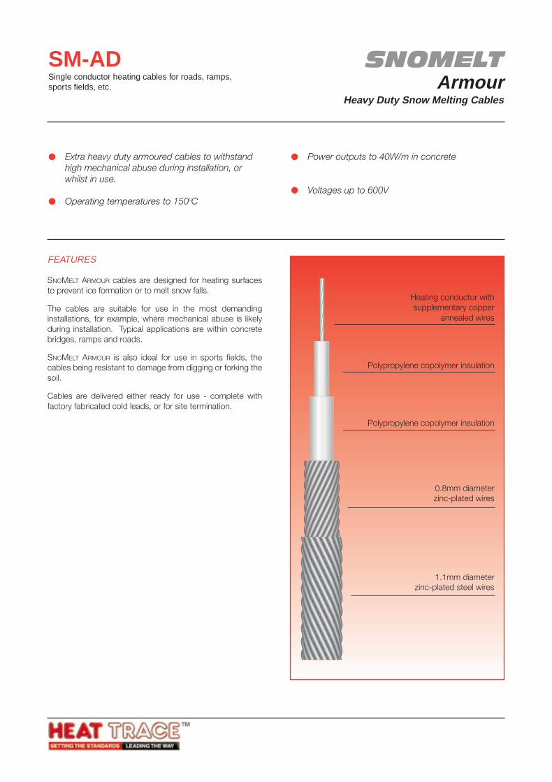
SNOMELTArmour
Heavy Duty Snow Melting Cables
SM-ADSingle conductor heating cables for roads, ramps,sports fields, etc.
FEATURES
SNOMELT ARMOUR cables are designed for heating surfacesto prevent ice formation or to melt snow falls.
The cables are suitable for use in the most demandinginstallations, for example, where mechanical abuse is likelyduring installation. Typical applications are within concretebridges, ramps and roads.
SNOMELT ARMOUR is also ideal for use in sports fields, thecables being resistant to damage from digging or forking thesoil.
Cables are delivered either ready for use - complete withfactory fabricated cold leads, or for site termination.
Extra heavy duty armoured cables to withstandhigh mechanical abuse during installation, orwhilst in use.
Operating temperatures to 150oC
Power outputs to 40W/m in concrete
Voltages up to 600V
Heating conductor withsupplementary copper
annealed wires
Polypropylene copolymer insulation
Polypropylene copolymer insulation
0.8mm diameterzinc-plated wires
1.1mm diameterzinc-plated steel wires
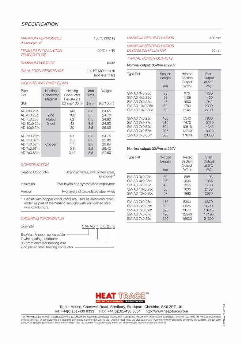
MINIMUM BENDING RADIUS 400mm
MINIMUM BENDING RADIUSDURING INSTALLATION 80mm
TYPICAL POWER OUTPUTS
NNoommiinnaall oouuttppuutt:: 3355WW//mm aatt 222200VV
Type Ref Section Heated StartLength Section Output
Output at 5oC(m) (W/m) (W)
SM-AD 3x0.25c 28 975 1280SM-AD 4x0.25c 33 1108 1450SM-AD 7x0.25c 43 1500 1945SM-AD 10x0.25c 52 1790 2300SM-AD 10x0.30c 63 2145 2730
SM-AD 7x0.28m 160 5540 7900SM-AD 7x0.37m 215 7470 10270SM-AD 7x0.52m 304 10618 14345SM-AD 7x0.67m 395 13760 18328SM-AD 7x0.85m 500 17600 23300
NNoommiinnaall oouuttppuutt:: 3300WW//mm aatt 222200VV
Type Ref Section Heated StartLength Section Output
Output at 5oC(m) (W/m) (W)
SM-AD 3x0.25c 30 898 1195SM-AD 4x0.25c 35 1030 1365SM-AD 7x0.25c 47 1355 1780SM-AD 10x0.25c 56 1635 2135SM-AD 10x0.30c 67 1980 2570
SM-AD 7x0.28m 178 5300 6670SM-AD 7x0.37m 230 6825 9600SM-AD 7x0.52m 325 9670 13415SM-AD 7x0.67m 420 12540 17195SM-AD 7x0.85m 550 16600 21200
SPECIFICATION
Tracer House, Cromwell Road, Bredbury, Stockport, Cheshire, SK6 2RF, UKTel: +44(0)161-430 8333 Fax: +44(0)161-430 8654 http://www.heat-trace.com
The information given herein, including drawings, illustrations and schematics (which are intended for illustration purposes only), is believed to be reliable. However, Heat Trace Ltd makes no warrantiesas to its accuracy or completeness and disclaims any liability in connection with its use. Users of Heat Trace Ltd products should make their own evaluation to determine the suitability of each suchproduct for specific applications. In no way will Heat Trace Ltd be liable for any damages arising out of the misuse, resale or use of the product.
HP
DS
xxx
06/0
2 D
raft
MAXIMUM PERMISSIBLE 150°C (302°F)de-energised
MINIMUM INSTALLATION –20°C (–4°F)TEMPERATURE
MAXIMUM VOLTAGE 600V
INSULATION RESISTANCE 1 x 10⁵ MOhm x m(not less than)
WEIGHTS AND DIMENSIONS
Type Heating Heating Nom. WeightRef Conductor Conductor Dims.
Material ResistanceSM- (Ohms/100m) (mm) (kg/100m)
AD 3x0.25c 145 8.5 24.65AD 4x0.25c Zinc 108 8.5 24.70AD 7x0.25c Plated 62 8.5 24.80AD 10x0.25c Steel 43 8.5 24.90AD 10x0.30c 30 8.5 25.05
AD 7x0.28m 4.1 8.5 24.75AD 7x0.37m 2.5 8.5 25.06AD 7x0.52m Copper 1.4 8.5 25.64AD 7x0.67m 0.8 8.5 26.40AD 7x0.85m 0.45 8.5 27.60
CONSTRUCTION
Heating Conductor Stranded wires, zinc plated steel,or copper*
Insulation Two-layers of polypropylene copolymer
Armour Two layers of zinc-plated steel wires
* Cables with copper conductors are used as armoured “cold-ends” as part of the heating sections with zinc-plated steelwire conductors.
ORDERING INFORMATION
Example SM-AD 7 x 0 .25 c
SNOMELT ARMOUR series cable7 wire heating conductor0.25mm diameter heating wireZinc plated steel heating conductor
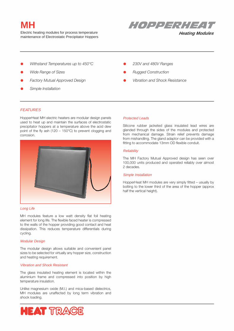
HOPPERHEATHeating Modules
MHElectric heating modules for process temperaturemaintenance of Electrostatic Precipitator Hoppers
FEATURES
HopperHeat MH electric heaters are modular design panelsused to heat up and maintain the surfaces of electrostaticprecipitator hoppers at a temperature above the acid dewpoint of the fly ash (120 – 150°C) to prevent clogging andcorrosion.
Long Life
MH modules feature a low watt density flat foil heatingelement for long life. The flexible faced heater is compressedto the walls of the hopper providing good contact and heatdissipation. This reduces temperature differentials duringcycling.
Modular Design
The modular design allows suitable and convenient panelsizes to be selected for virtually any hopper size, constructionand heating requirement.
Vibration and Shock Resistant
The glass insulated heating element is located within thealuminium frame and compressed into position by hightemperature insulation.
Unlike magnesium oxide (M.I.) and mica-based dielectrics,MH modules are unaffected by long term vibration andshock loading.
Withstand Temperatures up to 450°C
Wide Range of Sizes
Factory Mutual Approved Design
Simple Installation
230V and 480V Ranges
Rugged Construction
Vibration and Shock Resistance
Protected Leads
Silicone rubber jacketed glass insulated lead wires areglanded through the sides of the modules and protectedfrom mechanical damage. Strain relief prevents damagefrom mishandling. The gland adaptor can be provided with afitting to accommodate 13mm OD flexible conduit.
Reliability
The MH Factory Mutual Approved design has seen over100,000 units produced and operated reliably over almost2 decades.
Simple Installation
HopperHeat MH modules are very simply fitted – usually bybolting to the lower third of the area of the hopper (approxhalf the vertical height).
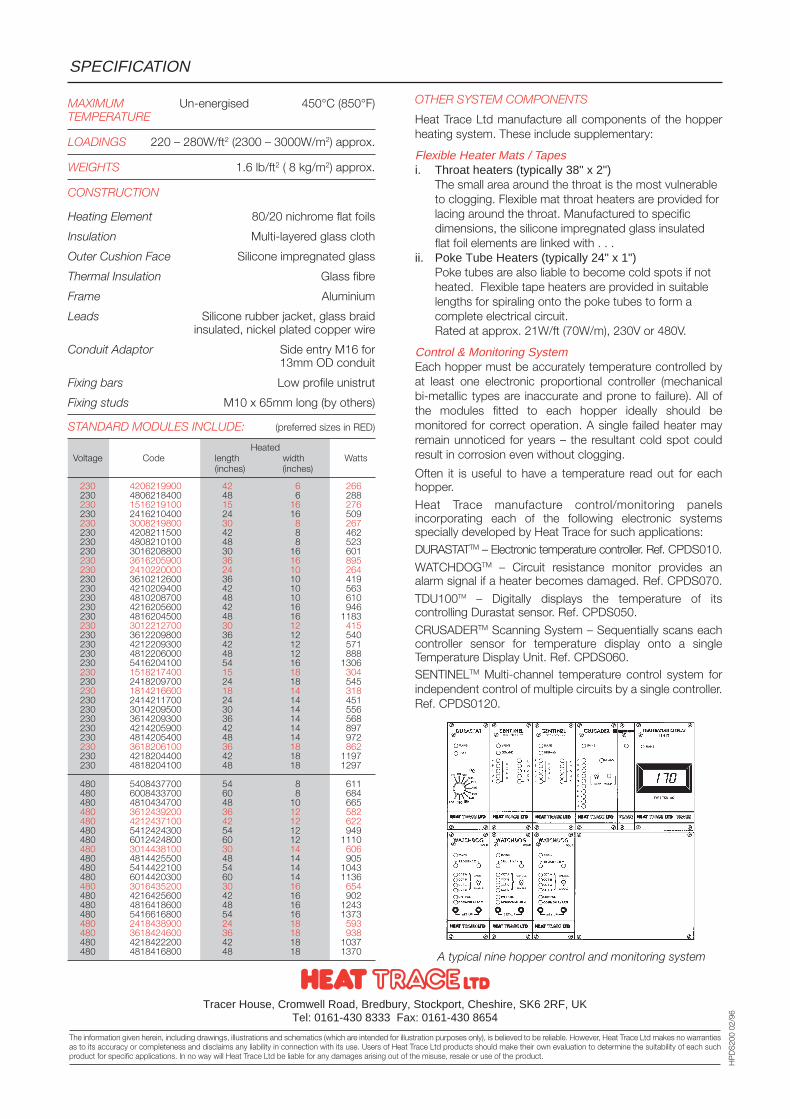
SPECIFICATION
Tracer House, Cromwell Road, Bredbury, Stockport, Cheshire, SK6 2RF, UKTel: 0161-430 8333 Fax: 0161-430 8654
The information given herein, including drawings, illustrations and schematics (which are intended for illustration purposes only), is believed to be reliable. However, Heat Trace Ltd makes no warrantiesas to its accuracy or completeness and disclaims any liability in connection with its use. Users of Heat Trace Ltd products should make their own evaluation to determine the suitability of each suchproduct for specific applications. In no way will Heat Trace Ltd be liable for any damages arising out of the misuse, resale or use of the product.
HP
DS
200
02/9
6
OTHER SYSTEM COMPONENTS
Heat Trace Ltd manufacture all components of the hopperheating system. These include supplementary:
Flexible Heater Mats / Tapesi. Throat heaters (typically 38" x 2")
The small area around the throat is the most vulnerableto clogging. Flexible mat throat heaters are provided forlacing around the throat. Manufactured to specificdimensions, the silicone impregnated glass insulatedflat foil elements are linked with . . .
ii. Poke Tube Heaters (typically 24" x 1")Poke tubes are also liable to become cold spots if notheated. Flexible tape heaters are provided in suitablelengths for spiraling onto the poke tubes to form acomplete electrical circuit.Rated at approx. 21W/ft (70W/m), 230V or 480V.
Control & Monitoring SystemEach hopper must be accurately temperature controlled byat least one electronic proportional controller (mechanicalbi-metallic types are inaccurate and prone to failure). All ofthe modules fitted to each hopper ideally should bemonitored for correct operation. A single failed heater mayremain unnoticed for years – the resultant cold spot couldresult in corrosion even without clogging.
Often it is useful to have a temperature read out for eachhopper.
Heat Trace manufacture control/monitoring panelsincorporating each of the following electronic systemsspecially developed by Heat Trace for such applications:DURASTATTM – Electronic temperature controller. Ref. CPDS010.
WATCHDOGTM – Circuit resistance monitor provides analarm signal if a heater becomes damaged. Ref. CPDS070.
TDU100TM – Digitally displays the temperature of itscontrolling Durastat sensor. Ref. CPDS050.
CRUSADERTM Scanning System – Sequentially scans eachcontroller sensor for temperature display onto a singleTemperature Display Unit. Ref. CPDS060.SENTINELTM Multi-channel temperature control system forindependent control of multiple circuits by a single controller.Ref. CPDS0120.
MAXIMUM Un-energised 450°C (850°F)TEMPERATURE
LOADINGS 220 – 280W/ft2 (2300 – 3000W/m2) approx.
WEIGHTS 1.6 lb/ft2 ( 8 kg/m2) approx.
CONSTRUCTION
Heating Element 80/20 nichrome flat foils
Insulation Multi-layered glass cloth
Outer Cushion Face Silicone impregnated glass
Thermal Insulation Glass fibre
Frame Aluminium
Leads Silicone rubber jacket, glass braidinsulated, nickel plated copper wire
Conduit Adaptor Side entry M16 for13mm OD conduit
Fixing bars Low profile unistrut
Fixing studs M10 x 65mm long (by others)
STANDARD MODULES INCLUDE: (preferred sizes in RED)
HeatedVoltage Code length width Watts
(inches) (inches)
230 4206219900 42 6 266230 4806218400 48 6 288230 1516219100 15 16 276230 2416210400 24 16 509230 3008219800 30 8 267230 4208211500 42 8 462230 4808210100 48 8 523230 3016208800 30 16 601230 3616205900 36 16 895230 2410220000 24 10 264230 3610212600 36 10 419230 4210209400 42 10 563230 4810208700 48 10 610230 4216205600 42 16 946230 4816204500 48 16 1183230 3012212700 30 12 415230 3612209800 36 12 540230 4212209300 42 12 571230 4812206000 48 12 888230 5416204100 54 16 1306230 1518217400 15 18 304230 2418209700 24 18 545230 1814216600 18 14 318230 2414211700 24 14 451230 3014209500 30 14 556230 3614209300 36 14 568230 4214205900 42 14 897230 4814205400 48 14 972230 3618206100 36 18 862230 4218204400 42 18 1197230 4818204100 48 18 1297
480 5408437700 54 8 611480 6008433700 60 8 684480 4810434700 48 10 665480 3612439200 36 12 582480 4212437100 42 12 622480 5412424300 54 12 949480 6012424800 60 12 1110480 3014438100 30 14 606480 4814425500 48 14 905480 5414422100 54 14 1043480 6014420300 60 14 1136480 3016435200 30 16 654480 4216425600 42 16 902480 4816418600 48 16 1243480 5416616800 54 16 1373480 2418438900 24 18 593480 3618424600 36 18 938480 4218422200 42 18 1037480 4818416800 48 18 1370 A typical nine hopper control and monitoring system
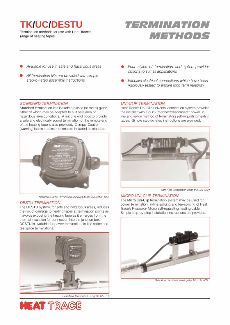
TERMINATIONMETHODS
TK/UC/DESTUTermination methods for use with Heat Trace’srange of heating tapes
STANDARD TERMINATIONStandard termination kits include a plastic (or metal) gland,either of which may be adapted to suit safe area orhazardous area conditions. A silicone end boot to providea safe and electrically sound termination of the remote endof the heating tape is also provided. Crimps, Caution(warning) labels and instructions are included as standard.
DESTU TERMINATIONThe DESTU system, for safe and hazardous areas, reducesthe risk of damage to heating tapes at termination points asit avoids exposing the heating tape as it emerges from thethermal insulation for connection into the junction box.DESTU is available for power termination, in-line splice andtee splice terminations.
Available for use in safe and hazardous areas
All termination kits are provided with simplestep-by-step assembly instructions
Four styles of termination and splice providesoptions to suit all applications
Effective electrical connections which have beenrigorously tested to ensure long term reliability
UNI-CLIP TERMINATIONHeat Trace’s Uni-Clip universal connection system providesthe installer with a quick “connect/disconnect” power, in-line and splice method of terminating self-regulating heatingtapes. Simple step-by-step instructions are provided.
MICRO UNI-CLIP TERMINATIONThe Micro Uni-Clip termination system may be used forpower termination, in-line splicing and tee-splicing of HeatTrace’s FREEZSTOP MICRO self-regulating heating cable.Simple step-by-step installation instructions are provided.
Safe Area Termination using the Micro Uni-Clip
Hazardous Area Termination using JB9000/EX Junction Box
Safe Area Termination using the UNI-CLIP
Safe Area Termination using the DESTU
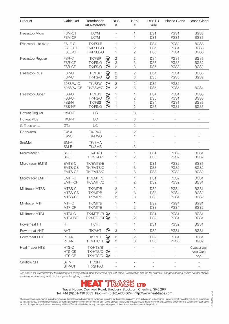
AP
DS
040
03/0
0Tracer House, Cromwell Road, Bredbury, Stockport, Cheshire, SK6 2RFTel: +44 (0)161-430 8333 Fax: +44 (0)161-430 8654 http://www.heat-trace.com
The information given herein, including drawings, illustrations and schematics (which are intended for illustration purposes only), is believed to be reliable. However, Heat Trace Ltd makes no warrantiesas to its accuracy or completeness and disclaims any liability in connection with its use. Users of Heat Trace Ltd products should make their own evaluation to determine the suitability of each suchproduct for specific applications. In no way will Heat Trace Ltd be liable for any damages arising out of the misuse, resale or use of the product.
Product Cable Ref Termination BPS BES DESTU Plastic Gland Brass GlandKit Reference # # Seal
Freezstop Micro FSM-CT UC/M - 1 DS1 PGS1 BGS3FSM-CF UC/M - 1 DS1 PGS1 BGS3
Freezstop Lite extra FSLE-C TK/FSLE 1 1 DS4 PGS2 BGS3FSLE-CT TK/FSLE/O 1 2 DS5 PGS1 BGS3FSLE-CF TK/FSLE/O 1 2 DS5 PGS1 BGS3
Freezstop Regular FSR-C TK/FSR 2 2 DS4 PGS3 BGS3FSR-CT TK/FS/O 2 3 DS5 PGS3 BGS2FSR-CF TK/FS/O 2 3 DS5 PGS3 BGS2
Freezstop Plus FSP-C TK/FSP 2 2 DS4 PGS1 BGS3FSP-CF TK/FS/O 2 3 DS5 PGS3 BGS2
50FSPw-C TK/FSW 2 2 DS5 PGS5 -50FSPw-CF TK/FSW/O 2 3 DS5 PGS5 BGS4
Freezstop Super FSS-C TK/FSS 1 1 DS4 PGS1 BGS3FSS-CF TK/FS/O 1 2 DS5 PGS1 BGS3FSS-N TK/FSS 1 1 DS4 PGS1 BGS3FSS-NF TK/FS/O 1 2 DS5 PGS1 BGS3
Hotwat Regular HWR-T UC - 3 - - -
Hotwat Plus HWP-T UC - 3 - - -
G-Trace extra GTe UC - 2 - - -
Floorwarm FW-A TK/FWA - 2 - - -FW-C TK/FWC - 1 - - -
SnoMelt SM-A TK/SMA - 1 - - -SM-B TK/SMB - 3 - - -
Microtracer ST ST-C TK/ST/B 1 1 DS1 PGS2 BGS1ST-CT TK/ST/OP 1 2 DS3 PGS2 BGS2
Microtracer EMTS EMTS-C TK/EMTS/B 1 1 DS1 PGS2 BGS1EMTS-CS TK/EMTS/O 1 3 DS3 PGS2 BGS2EMTS-CF TK/EMTS/O 1 3 DS3 PGS2 BGS2
Microtracer EMTF EMTF-C TK/EMTF/B 1 1 DS1 PGS2 BGS1EMTF-CF TK/EMTF/O 1 2 DS2 PGS2 BGS1
Minitracer MTSS MTSS-C TK/MT/B 2 2 DS2 PGS4 BGS1MTSS-CS TK/MT/B 2 3 DS3 PGS4 BGS2MTSS-CF TK/MT/B 2 3 DS3 PGS4 BGS2
Minitracer MTF MTF-C TK/MT/B 1 1 DS2 PGS4 BGS1MTF-CF TK/MT/B 1 2 DS3 PGS4 BGS2
Minitracer MTFJ MTFJ-C TK/MTFJ/B 1 1 DS1 PGS1 BGS1MTFJ-CF TK/MTFJ/OF 1 2 DS2 PGS1 BGS1
Powerheat HT HT TK/HT 1 1 DS1 PGS2 BGS1
Powerheat AHT AHT TK/AHT 3 2 DS2 PGS1 BGS1
Powerheat PHT PHT-N TK/PHT 2 2 DS2 PGS1 BGS1PHT-NF TK/PHT/OF 2 3 DS3 PGS3 BGS2
Heat Tracer HTS HTS-C TK/HTS/B - - - - Contact yourHTS-CS TK/HTS/O - - - - Heat TraceHTS-CF TK/HTS/O - - - - Rep.
Snoflow SFP SFP-T TK/SFP - - - - -SFP-CT TK/SFP/O - - - - -
The above list is provided for the majority of heating cables manufacturered by Heat Trace. Termination kits for, for example, Longline heating cables are not shownas these tend to be specific to the style of Longline provided.
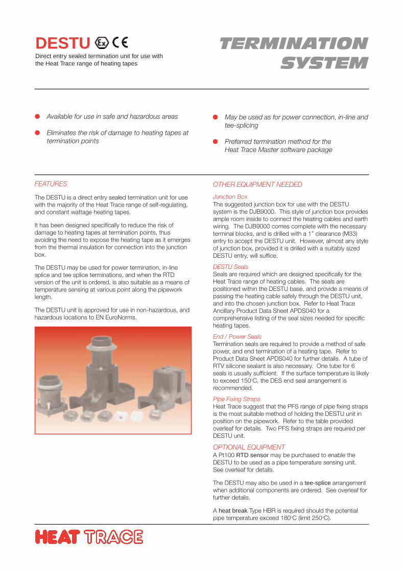
TERMINATIONSYSTEM
DESTUDirect entry sealed termination unit for use withthe Heat Trace range of heating tapes
FEATURES
The DESTU is a direct entry sealed termination unit for usewith the majority of the Heat Trace range of self-regulating,and constant wattage heating tapes.
It has been designed specifically to reduce the risk ofdamage to heating tapes at termination points, thusavoiding the need to expose the heating tape as it emergesfrom the thermal insulation for connection into the junctionbox.
The DESTU may be used for power termination, in-linesplice and tee splice terminations, and when the RTDversion of the unit is ordered, is also suitable as a means oftemperature sensing at various point along the pipeworklength.
The DESTU unit is approved for use in non-hazardous, andhazardous locations to EN EuroNorms.
Available for use in safe and hazardous areas
Eliminates the risk of damage to heating tapes attermination points
May be used as for power connection, in-line andtee-splicing
Preferred termination method for theHeat Trace Master software package
OTHER EQUIPMENT NEEDED
Junction BoxThe suggested junction box for use with the DESTUsystem is the DJB9000. This style of junction box providesample room inside to connect the heating cables and earthwiring. The DJB9000 comes complete with the necessaryterminal blocks, and is drilled with a 1” clearance (M33)entry to accept the DESTU unit. However, almost any styleof junction box, provided it is drilled with a suitably sizedDESTU entry, will suffice.
DESTU SealsSeals are required which are designed specifically for theHeat Trace range of heating cables. The seals arepositioned within the DESTU base, and provide a means ofpassing the heating cable safely through the DESTU unit,and into the chosen junction box. Refer to Heat TraceAncillary Product Data Sheet APDS040 for acomprehensive listing of the seal sizes needed for specificheating tapes.
End / Power SealsTermination seals are required to provide a method of safepower, and end termination of a heating tape. Refer toProduct Data Sheet APDS040 for further details. A tube ofRTV silicone sealant is also necessary. One tube for 6seals is usually sufficient. If the surface temperature is likelyto exceed 150oC, the DES end seal arrangement isrecommended.
Pipe Fixing StrapsHeat Trace suggest that the PFS range of pipe fixing strapsis the most suitable method of holding the DESTU unit inposition on the pipework. Refer to the table providedoverleaf for details. Two PFS fixing straps are required perDESTU unit.
OPTIONAL EQUIPMENTA Pt100 RTD sensor may be purchased to enable theDESTU to be used as a pipe temperature sensing unit.See overleaf for details.
The DESTU may also be used in a tee-splice arrangementwhen additional components are ordered. See overleaf forfurther details.
A heat break Type HBR is required should the potentialpipe temperature exceed 180oC (limit 250oC).
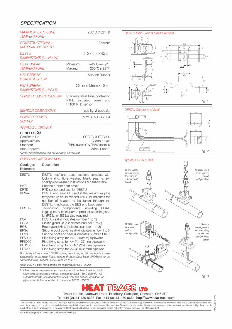
AP
DS
050
03/0
0Tracer House, Cromwell Road, Bredbury, Stockport, Cheshire, SK6 2RFTel: +44 (0)161-430 8333 Fax: +44 (0)161-430 8654 http://www.heat-trace.com
The information given herein, including drawings, illustrations and schematics (which are intended for illustration purposes only), is believed to be reliable. However, Heat Trace Ltd makes no warrantiesas to its accuracy or completeness and disclaims any liability in connection with its use. Users of Heat Trace Ltd products should make their own evaluation to determine the suitability of each suchproduct for specific applications. In no way will Heat Trace Ltd be liable for any damages arising out of the misuse, resale or use of the product.
MAXIMUM EXPOSURE 250°C (482°F )†
TEMPERATURE
CONSTRUCTIONAL Fortron®
MATERIAL OF DESTU
DESTU 110 x 114 x 42mmDIMENSIONS (L x H x W)
HEAT BREAK Minimum –45°C (–4.9°F)TEMPERATURE Maximum 250°C (482°F)
HEAT BREAK Silicone RubberCONSTRUCTION
HEAT BREAK 130mm x 62mm x 10mmDIMENSIONS (L x W x D)
SENSOR CONSTRUCTION Stainless steel tube containingPTFE insulated wires andPt100 RTD sensor.
SENSOR DIMENSIONS see fig. 2 opposite
SENSOR POWER Max. 40V DC 20VASUPPLY
APPROVAL DETAILS
CENELECCertificate No. SCS Ex 99E3089UApproval type Code EExeIIStandard EN50014:1992 & EN50019:1994Area Approval Zone 1 and 2Further National Approvals are available on request.
ORDERING INFORMATION
Catalogue DescriptionReference
DESTU DESTU ‘top’ and ‘base’ sections complete withlocking ring, fibre washer, blank seal, screw,shakeproof washer, instructions & caution label
HBR Silicone rubber heat breakDRTD RTD sensor and seal for DESTUDESnx DESTU end seal kit used if the maximum pipe
temperature could exceed 150oC (n indicates thenumber of heaters to be taken through theDESTU, x indicates the BES end boot size)
DESTU/T Tee-splicing components including LEK/Ulagging entry kit (separate product specific glandkit (PGSn or BGSn) also required).
DSn DESTU seal (n indicates number 1 to 5)PGSn Plastic gland kit (n indicates number 1 to 5)BGSn Brass gland kit (n indicates number 1 to 3)BPSn Silicone boot power seal (n indicates number 1 to 3)BESn Silicone boot end seal (n indicates number 1 to 3)PFS025 Pipe fixing strap for <= 2” (50mm) pipeworkPFS050 Pipe fixing strap for <= 5” (127mm) pipeworkPFS100 Pipe fixing strap for <=10” (254mm) pipeworkPFS200 Pipe fixing strap for <=24” (635mm) pipeworkFor details of the correct DESTU seals, gland kits, or silicone boots to use,please refer to the Heat Trace Ancillary Product Data Sheet APDS040, or thecomprehensive Product Guide Brochure PG010.
Note: 2 x PFS pipe fixing straps are required per DESTU unit
† Maximum temperature when the silicone rubber heat break is used.Maximum temperature without the heat break is 180oC (356oF). Werecommend use of a heat break for DESTU and silicone end seals onpipes intended for operation in the range 150oC - 250oC
SPECIFICATION
DESTU Unit - Top & Base Sections
fig. 1
DESTU Sensor and Seal
fig. 2
fig. 3
Typical DESTU uses
In-line spliceincorporatingthe siliconerubber heatbreak
Sensorarrangementincorporating
the siliconerubber heat
break
DESTU usedin a tee-spliceconfiguration
DESTU usedin an end of
circuitconfiguration
Fortron is a registered trademark of Hoechst Chemicals
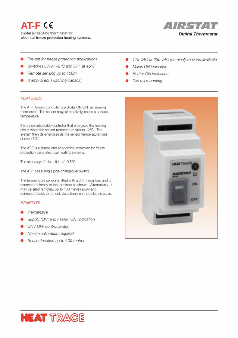
AIRSTATDigital Thermostat
AT-FDigital air sensing thermostat forelectrical freeze protection heating systems.
FEATURES
The AT-F AIRSTAT controller is a digital ON/OFF air sensingthermostat. The sensor may, alternatively, sense a surfacetemperature.
It is a non-adjustable controller that energises the heatingcircuit when the sensor temperature falls to +2°C. Thesystem then de-energises as the sensor temperature risesabove +5°C.
The AT-F is a simple and economical controller for freezeprotection using electrical heating systems.
The accuracy of this unit is +/- 0.5°C.
The AT-F has a single pole changeover switch.
The temperature sensor is fitted with a 3.5m long lead and isconnected directly to the terminals as shown. Alternatively, itmay be sited remotely, up to 100 metres away andconnected back to the unit via suitably earthed electric cable.
BENEFITS
Inexpensive
Supply ‘ON’ and heater ‘ON’ indication
ON / OFF control switch
No site calibration required
Sensor location up to 100 metres
Pre-set for freeze protection applications
Switches ON at +2°C and OFF at +5°C
Remote sensing up to 100m
8 amp direct switching capacity
115 VAC or 230 VAC (nominal) versions available
Mains ON indication
Heater ON indication
DIN rail mounting
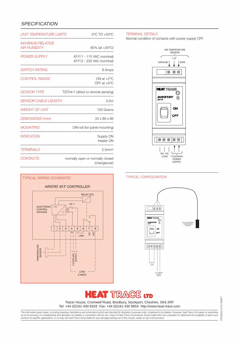
UNIT TEMPERATURE LIMITS 0oC TO +50oC
MAXIMUM RELATIVEAIR HUMIDITY 80% (at +35oC)
POWER SUPPLY AT-F/1 - 115 VAC (nominal)AT-F/2 - 230 VAC (nominal)
SWITCH RATING 8 Amps
CONTROL RANGE ON at +2oCOFF at +5oC
SENSOR TYPE TST04/1 (direct or remote sensing)
SENSOR CABLE LENGTH 3.5m
WEIGHT OF UNIT 100 Grams
DIMENSIONS (mm) 33 x 89 x 66
MOUNTING DIN rail (for panel mounting)
INDICATION Supply ONHeater ON
TERMINALS 2.5mm²
CONTACTS normally open or normally closed(changeover)
SPECIFICATION
Tracer House, Cromwell Road, Bredbury, Stockport, Cheshire, SK6 2RFTel: +44 (0)161-430 8333 Fax: +44 (0)161-430 8654 http://www.heat-trace.com
The information given herein, including drawings, illustrations and schematics (which are intended for illustration purposes only), is believed to be reliable. However, Heat Trace Ltd makes no warrantiesas to its accuracy or completeness and disclaims any liability in connection with its use. Users of Heat Trace Ltd products should make their own evaluation to determine the suitability of each suchproduct for specific applications. In no way will Heat Trace Ltd be liable for any damages arising out of the misuse, resale or use of the product.
CP
DS
250
01/0
1 D
RA
FT
TERMINAL DETAILSNormal condition of contacts with power supply OFF.
TYPICAL WIRING SCHEMATIC TYPICAL CONFIGURATION
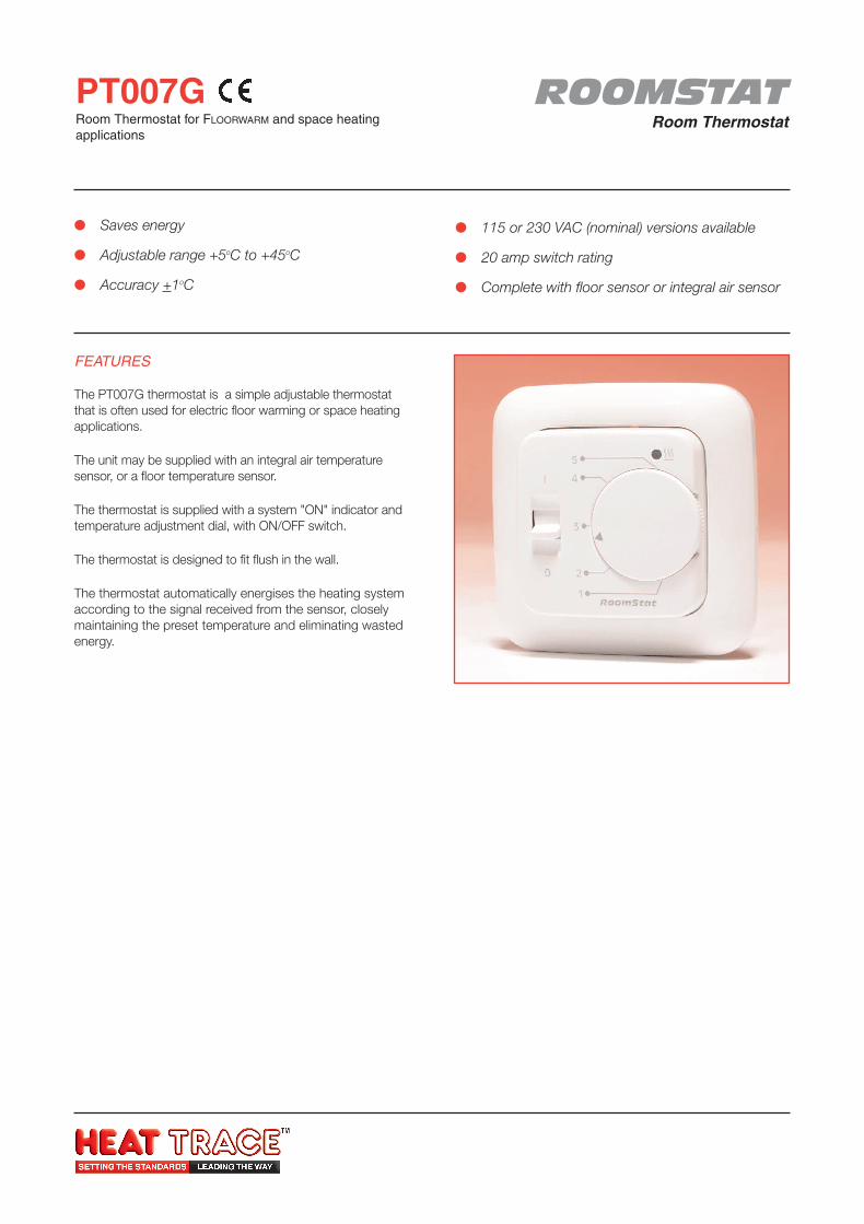
ROOMSTATRoom Thermostat
PT007GRoom Thermostat for FLOORWARM and space heatingapplications
FEATURES
The PT007G thermostat is a simple adjustable thermostatthat is often used for electric floor warming or space heatingapplications.
The unit may be supplied with an integral air temperaturesensor, or a floor temperature sensor.
The thermostat is supplied with a system "ON" indicator andtemperature adjustment dial, with ON/OFF switch.
The thermostat is designed to fit flush in the wall.
The thermostat automatically energises the heating systemaccording to the signal received from the sensor, closelymaintaining the preset temperature and eliminating wastedenergy.
Saves energy
Adjustable range +5oC to +45oC
Accuracy +1oC
115 or 230 VAC (nominal) versions available
20 amp switch rating
Complete with floor sensor or integral air sensor
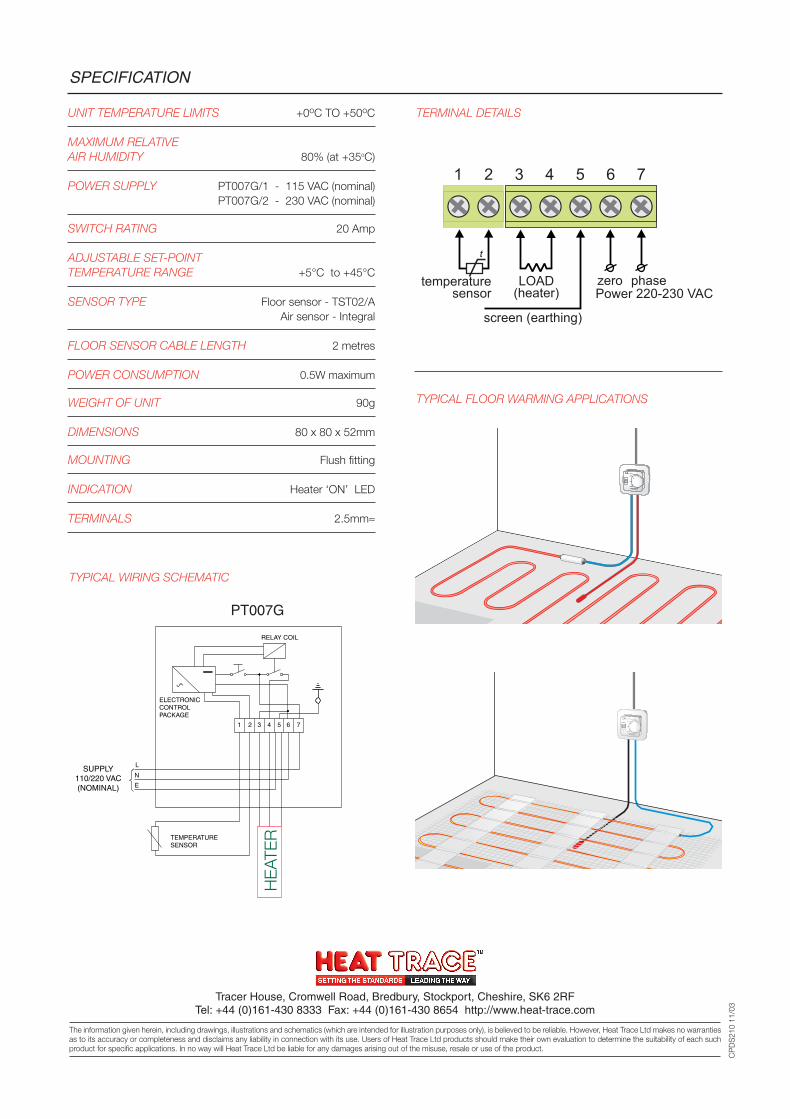
UNIT TEMPERATURE LIMITS +0oC TO +50oC
MAXIMUM RELATIVEAIR HUMIDITY 80% (at +35oC)
POWER SUPPLY PT007G/1 - 115 VAC (nominal) PT007G/2 - 230 VAC (nominal)
SWITCH RATING 20 Amp
ADJUSTABLE SET-POINTTEMPERATURE RANGE +5°C to +45°C
SENSOR TYPE Floor sensor - TST02/AAir sensor - Integral
FLOOR SENSOR CABLE LENGTH 2 metres
POWER CONSUMPTION 0.5W maximum
WEIGHT OF UNIT 90g
DIMENSIONS 80 x 80 x 52mm
MOUNTING Flush fitting
INDICATION Heater ‘ON’ LED
TERMINALS 2.5mm≈
SPECIFICATION
Tracer House, Cromwell Road, Bredbury, Stockport, Cheshire, SK6 2RFTel: +44 (0)161-430 8333 Fax: +44 (0)161-430 8654 http://www.heat-trace.com
The information given herein, including drawings, illustrations and schematics (which are intended for illustration purposes only), is believed to be reliable. However, Heat Trace Ltd makes no warrantiesas to its accuracy or completeness and disclaims any liability in connection with its use. Users of Heat Trace Ltd products should make their own evaluation to determine the suitability of each suchproduct for specific applications. In no way will Heat Trace Ltd be liable for any damages arising out of the misuse, resale or use of the product.
CP
DS
210
11/0
3
temperaturesensor
tt
Power 220-230 VACphasezeroLOAD
(heater)
screen (earthing)
7654321
TERMINAL DETAILS
TYPICAL FLOOR WARMING APPLICATIONS
RELAY COIL
ELECTRONIC CONTROL PACKAGE
1 2 3 4 5 6 7
L
N
E
SUPPLY 110/220 VAC (NOMINAL)
TEMPERATURE SENSOR
HE
ATE
R
PT007G
TYPICAL WIRING SCHEMATIC
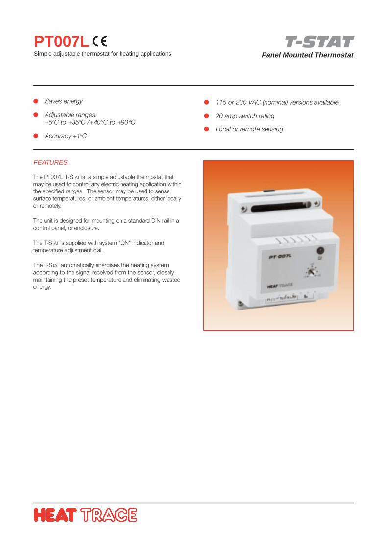
T-STATPanel Mounted Thermostat
PT007LSimple adjustable thermostat for heating applications
FEATURES
The PT007L T-STAT is a simple adjustable thermostat thatmay be used to control any electric heating application withinthe specified ranges. The sensor may be used to sensesurface temperatures, or ambient temperatures, either locallyor remotely.
The unit is designed for mounting on a standard DIN rail in acontrol panel, or enclosure.
The T-STAT is supplied with system "ON" indicator andtemperature adjustment dial.
The T-STAT automatically energises the heating systemaccording to the signal received from the sensor, closelymaintaining the preset temperature and eliminating wastedenergy.
Saves energy
Adjustable ranges:+5oC to +35oC /+40°C to +90°C
Accuracy +1oC
115 or 230 VAC (nominal) versions available
20 amp switch rating
Local or remote sensing
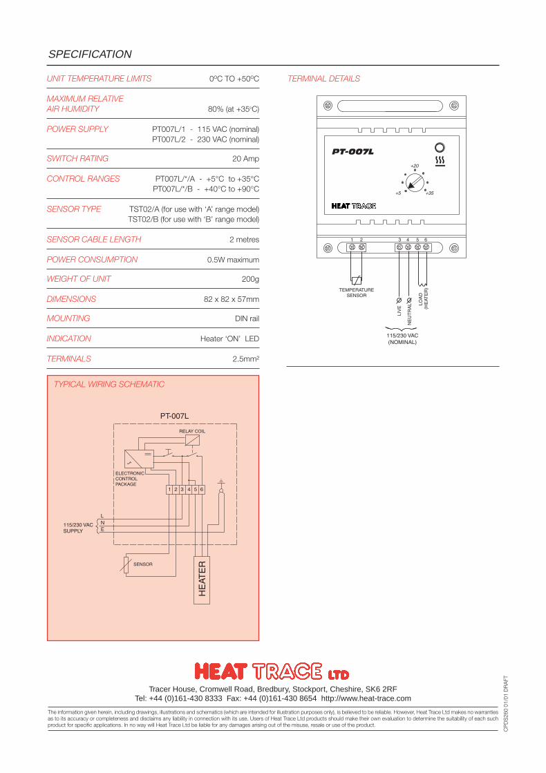
UNIT TEMPERATURE LIMITS 0oC TO +50oC
MAXIMUM RELATIVEAIR HUMIDITY 80% (at +35oC)
POWER SUPPLY PT007L/1 - 115 VAC (nominal) PT007L/2 - 230 VAC (nominal)
SWITCH RATING 20 Amp
CONTROL RANGES PT007L/*/A - +5°C to +35°CPT007L/*/B - +40°C to +90°C
SENSOR TYPE TST02/A (for use with ‘A’ range model)TST02/B (for use with ‘B’ range model)
SENSOR CABLE LENGTH 2 metres
POWER CONSUMPTION 0.5W maximum
WEIGHT OF UNIT 200g
DIMENSIONS 82 x 82 x 57mm
MOUNTING DIN rail
INDICATION Heater ‘ON’ LED
TERMINALS 2.5mm²
SPECIFICATION
Tracer House, Cromwell Road, Bredbury, Stockport, Cheshire, SK6 2RFTel: +44 (0)161-430 8333 Fax: +44 (0)161-430 8654 http://www.heat-trace.com
The information given herein, including drawings, illustrations and schematics (which are intended for illustration purposes only), is believed to be reliable. However, Heat Trace Ltd makes no warrantiesas to its accuracy or completeness and disclaims any liability in connection with its use. Users of Heat Trace Ltd products should make their own evaluation to determine the suitability of each suchproduct for specific applications. In no way will Heat Trace Ltd be liable for any damages arising out of the misuse, resale or use of the product.
CP
DS
260
01/0
1 D
RA
FT
TERMINAL DETAILS
TYPICAL WIRING SCHEMATIC
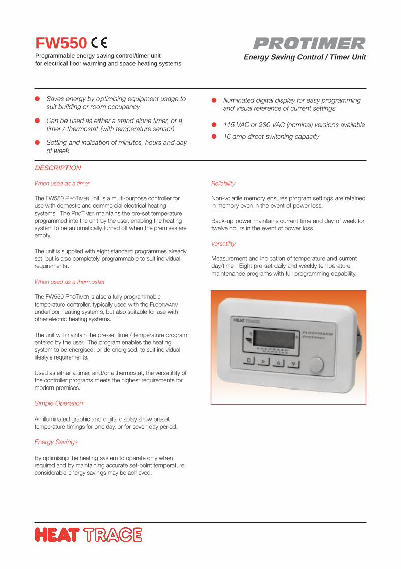
PROTIMEREnergy Saving Control / Timer Unit
FW550Programmable energy saving control/timer unit for electrical floor warming and space heating systems
DESCRIPTION
When used as a timer
The FW550 PROTIMER unit is a multi-purpose controller foruse with domestic and commercial electrical heatingsystems. The PROTIMER maintains the pre-set temperatureprogrammed into the unit by the user, enabling the heatingsystem to be automatically turned off when the premises areempty.
The unit is supplied with eight standard programmes alreadyset, but is also completely programmable to suit individualrequirements.
When used as a thermostat
The FW550 PROTIMER is also a fully programmabletemperature controller, typically used with the FLOORWARM
underfloor heating systems, but also suitable for use withother electric heating systems.
The unit will maintain the pre-set time / temperature programentered by the user. The program enables the heatingsystem to be energised, or de-energised, to suit individuallifestyle requirements.
Used as either a timer, and/or a thermostat, the versatitlity ofthe controller programs meets the highest requirements formodern premises.
Simple Operation
An illuminated graphic and digital display show presettemperature timings for one day, or for seven day period.
Energy Savings
By optimising the heating system to operate only whenrequired and by maintaining accurate set-point temperature,considerable energy savings may be achieved.
Saves energy by optimising equipment usage tosuit building or room occupancy
Can be used as either a stand alone timer, or atimer / thermostat (with temperature sensor)
Setting and indication of minutes, hours and dayof week
Illuminated digital display for easy programmingand visual reference of current settings
115 VAC or 230 VAC (nominal) versions available
16 amp direct switching capacity
Reliability
Non-volatile memory ensures program settings are retainedin memory even in the event of power loss.
Back-up power maintains current time and day of week fortwelve hours in the event of power loss.
Versatility
Measurement and indication of temperature and currentday/time. Eight pre-set daily and weekly temperaturemaintenance programs with full programming capability.
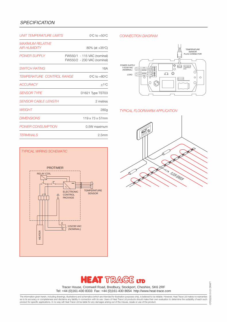
CONNECTION DIAGRAMUNIT TEMPERATURE LIMITS 0oC to +50oC
MAXIMUM RELATIVEAIR HUMIDITY 80% (at +35oC)
POWER SUPPLY FW550/1 - 115 VAC (nominal)FW550/2 - 230 VAC (nominal)
SWITCH RATING 16A
TEMPERATURE CONTROL RANGE 0oC to +80oC
ACCURACY +1oC
SENSOR TYPE D1621 Type TST03
SENSOR CABLE LENGTH 2 metres
WEIGHT 280g
DIMENSIONS 119 x 73 x 57mm
POWER CONSUMPTION 0.5W maximum
TERMINALS 2.5mm
SPECIFICATION
Tracer House, Cromwell Road, Bredbury, Stockport, Cheshire, SK6 2RFTel: +44 (0)161-430 8333 Fax: +44 (0)161-430 8654 http://www.heat-trace.com
The information given herein, including drawings, illustrations and schematics (which are intended for illustration purposes only), is believed to be reliable. However, Heat Trace Ltd makes no warrantiesas to its accuracy or completeness and disclaims any liability in connection with its use. Users of Heat Trace Ltd products should make their own evaluation to determine the suitability of each suchproduct for specific applications. In no way will Heat Trace Ltd be liable for any damages arising out of the misuse, resale or use of the product.
CP
DS
200
01/0
1 D
RA
FT
TYPICAL WIRING SCHEMATIC
PROTIMER
RELAY COIL
ELECTRONICCONTROL PACKAGE
TEMPERATURESENSOR
115/230 VAC(NOMINAL)
HE
ATE
R
ELN
TYPICAL FLOORWARM APPLICATION
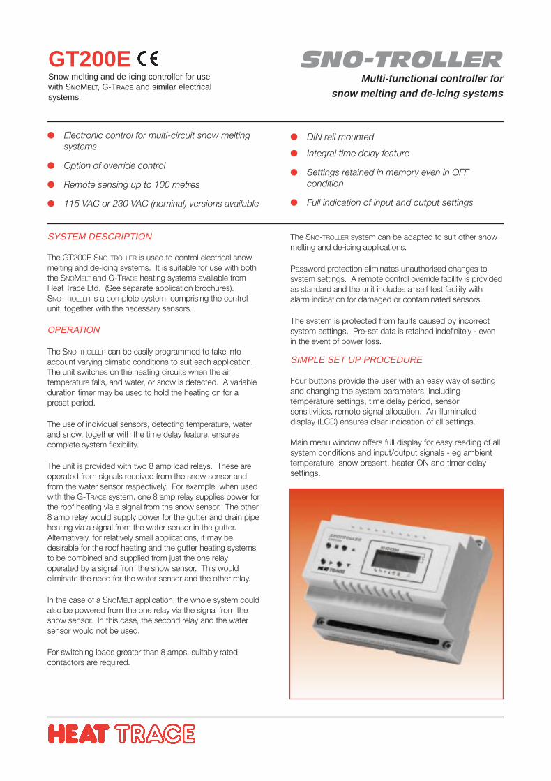
SNO-TROLLERMulti-functional controller for
snow melting and de-icing systems
GT200ESnow melting and de-icing controller for usewith SNOMELT, G-TRACE and similar electricalsystems.
SYSTEM DESCRIPTION
The GT200E SNO-TROLLER is used to control electrical snowmelting and de-icing systems. It is suitable for use with boththe SNOMELT and G-TRACE heating systems available fromHeat Trace Ltd. (See separate application brochures).SNO-TROLLER is a complete system, comprising the controlunit, together with the necessary sensors.
OPERATION
The SNO-TROLLER can be easily programmed to take intoaccount varying climatic conditions to suit each application.The unit switches on the heating circuits when the airtemperature falls, and water, or snow is detected. A variableduration timer may be used to hold the heating on for apreset period.
The use of individual sensors, detecting temperature, waterand snow, together with the time delay feature, ensurescomplete system flexibility.
The unit is provided with two 8 amp load relays. These areoperated from signals received from the snow sensor andfrom the water sensor respectively. For example, when usedwith the G-TRACE system, one 8 amp relay supplies power forthe roof heating via a signal from the snow sensor. The other8 amp relay would supply power for the gutter and drain pipeheating via a signal from the water sensor in the gutter.Alternatively, for relatively small applications, it may bedesirable for the roof heating and the gutter heating systemsto be combined and supplied from just the one relayoperated by a signal from the snow sensor. This wouldeliminate the need for the water sensor and the other relay.
In the case of a SNOMELT application, the whole system couldalso be powered from the one relay via the signal from thesnow sensor. In this case, the second relay and the watersensor would not be used.
For switching loads greater than 8 amps, suitably ratedcontactors are required.
Electronic control for multi-circuit snow meltingsystems
Option of override control
Remote sensing up to 100 metres
115 VAC or 230 VAC (nominal) versions available
DIN rail mounted
Integral time delay feature
Settings retained in memory even in OFFcondition
Full indication of input and output settings
The SNO-TROLLER System can be adapted to suit other snowmelting and de-icing applications.
Password protection eliminates unauthorised changes tosystem settings. A remote control override facility is providedas standard and the unit includes a self test facility withalarm indication for damaged or contaminated sensors.
The system is protected from faults caused by incorrectsystem settings. Pre-set data is retained indefinitely - evenin the event of power loss.
SIMPLE SET UP PROCEDURE
Four buttons provide the user with an easy way of settingand changing the system parameters, includingtemperature settings, time delay period, sensorsensitivities, remote signal allocation. An illuminateddisplay (LCD) ensures clear indication of all settings.
Main menu window offers full display for easy reading of allsystem conditions and input/output signals - eg ambienttemperature, snow present, heater ON and timer delaysettings.
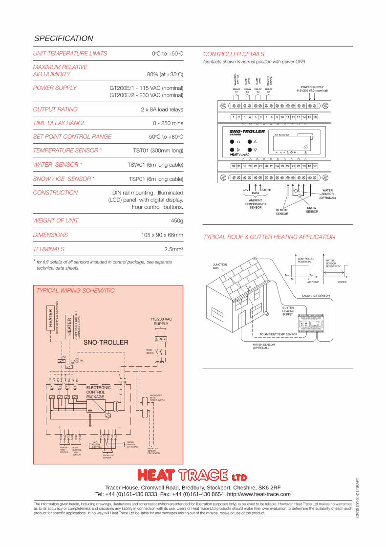
CONTROLLER DETAILS(contacts shown in normal position with power OFF)
UNIT TEMPERATURE LIMITS 0oC to +50oC
MAXIMUM RELATIVEAIR HUMIDITY 80% (at +35oC)
POWER SUPPLY GT200E/1 - 115 VAC (nominal)GT200E/2 - 230 VAC (nominal)
OUTPUT RATING 2 x 8A load relays
TIME DELAY RANGE 0 - 250 mins
SET POINT CONTROL RANGE -50oC to +80oC
TEMPERATURE SENSOR * TST01 (300mm long)
WATER SENSOR * TSW01 (6m long cable)
SNOW / ICE SENSOR * TSP01 (6m long cable)
CONSTRUCTION DIN rail mounting. Illuminated(LCD) panel with digital display.
Four control buttons.
WEIGHT OF UNIT 450g
DIMENSIONS 105 x 90 x 66mm
TERMINALS 2.5mm²
* for full details of all sensors included in control package, see separate technical data sheets.
SPECIFICATION
Tracer House, Cromwell Road, Bredbury, Stockport, Cheshire, SK6 2RFTel: +44 (0)161-430 8333 Fax: +44 (0)161-430 8654 http://www.heat-trace.com
The information given herein, including drawings, illustrations and schematics (which are intended for illustration purposes only), is believed to be reliable. However, Heat Trace Ltd makes no warrantiesas to its accuracy or completeness and disclaims any liability in connection with its use. Users of Heat Trace Ltd products should make their own evaluation to determine the suitability of each suchproduct for specific applications. In no way will Heat Trace Ltd be liable for any damages arising out of the misuse, resale or use of the product.
CP
DS
190
01/0
1 D
RA
FT
TYPICAL WIRING SCHEMATIC
TYPICAL ROOF & GUTTER HEATING APPLICATION

Capstat Type CT-FL
Capstat Type CT
CAPSTATCapillary Thermostats
CTTemperature control of heat tracecircuits in safe or hazardous areas
FEATURES
Capstats are temperature adjustable ON-OFF thermostatscomprising a liquid filled sensing bulb conected to anelectrical switch via a capillary tube.
Expansion of the liquid on rise in temperature causes theswitch to open, and on cooling, it closes.
Capstats may control surface temperatures such as pipes orvessels, or the sensing bulb may be positionad to sensethe air temperature.
They may be used to provide process temperature controlin safe or Zone 1 or 2 hazardous areas by switching theheaing circuits at the desired temperature and are availableto suit Group llA, llB or llC gases.(EEx’d’ barrier glands are madatory).
The addition of a high limit cut-out switch (as provided withthe Capstat-Dual version) is specified when the heat tracingscheme will not stabilise at a safe temperature withoutprocess control. It will operate if the process control switchfails or if an unsafe process temperature occurs.
OPTIONS
CT Capstat for use in safe areas.
CT-FL Hazardous area EEx’d Capstat suitable for usein Zone 1 and 2 hazardous areas, Gas GroupsllA, llB and llC.
CT ../X Optional armoured capillary provides additionalmechanical protection for the capillary tube(s).
CT ..DUAL Over-temperature lock-out (20° - 300°C)(Factory preset)
Three wide span temperature ranges
Stainless steel sensor and capillary tube
Optional over-temperature lock-out
ATEX approved for use in Zone 1 and 2hazardous areas (CT-FL version)
Enclosures suitable for Gas groups llA, llB & llC
Optional stainless steel armoured capillary
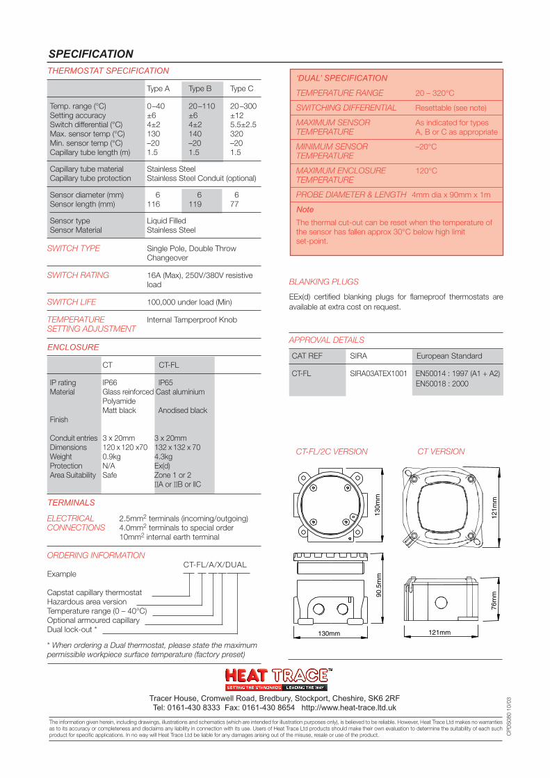
130m
m
130mm
90.5
mm
121m
m76
mm
121mm
THERMOSTAT SPECIFICATION
Type A Type B Type C
Temp. range (°C) 0–40 20–110 20–300Setting accuracy ±6 ±6 ±12Switch differential (°C) 4±2 4±2 5.5±2.5Max. sensor temp (°C) 130 140 320Min. sensor temp (°C) –20 –20 –20Capillary tube length (m) 1.5 1.5 1.5
Capillary tube material Stainless SteelCapillary tube protection Stainless Steel Conduit (optional)
Sensor diameter (mm) 6 6 6Sensor length (mm) 116 119 77
Sensor type Liquid FilledSensor Material Stainless Steel
SWITCH TYPE Single Pole, Double ThrowChangeover
SWITCH RATING 16A (Max), 250V/380V resistiveload
SWITCH LIFE 100,000 under load (Min)
TEMPERATURE Internal Tamperproof KnobSETTING ADJUSTMENT
ENCLOSURE
CT CT-FL
IP rating IP66 IP65Material Glass reinforced Cast aluminium
PolyamideMatt black Anodised black
Finish
Conduit entries 3 x 20mm 3 x 20mmDimensions 120 x 120 x70 132 x 132 x 70Weight 0.9kg 4.3kgProtection N/A Ex(d)Area Suitability Safe Zone 1 or 2
IIA or IIB or llC
TERMINALS
ELECTRICAL 2.5mm2 terminals (incoming/outgoing)CONNECTIONS 4.0mm2 terminals to special order
10mm2 internal earth terminal
ORDERING INFORMATIONCT-FL/A/X/DUAL
Example
Capstat capillary thermostatHazardous area versionTemperature range (0 – 40°C)Optional armoured capillaryDual lock-out *
* When ordering a Dual thermostat, please state the maximumpermissible workpiece surface temperature (factory preset)
‘DUAL’ SPECIFICATION
TEMPERATURE RANGE 20 – 320°C
SWITCHING DIFFERENTIAL Resettable (see note)
MAXIMUM SENSOR As indicated for typesTEMPERATURE A, B or C as appropriate
MINIMUM SENSOR –20°CTEMPERATURE
MAXIMUM ENCLOSURE 120°CTEMPERATURE
PROBE DIAMETER & LENGTH 4mm dia x 90mm x 1m
NoteThe thermal cut-out can be reset when the temperature ofthe sensor has fallen approx 30°C below high limitset-point.
BLANKING PLUGS
EEx(d) certified blanking plugs for flameproof thermostats areavailable at extra cost on request.
APPROVAL DETAILS
CAT REF SIRA European Standard
CT-FL SIRA03ATEX1001 EN50014 : 1997 (A1 + A2)EN50018 : 2000
SPECIFICATION
Tracer House, Cromwell Road, Bredbury, Stockport, Cheshire, SK6 2RFTel: 0161-430 8333 Fax: 0161-430 8654 http://www.heat-trace.ltd.uk
The information given herein, including drawings, illustrations and schematics (which are intended for illustration purposes only), is believed to be reliable. However, Heat Trace Ltd makes no warrantiesas to its accuracy or completeness and disclaims any liability in connection with its use. Users of Heat Trace Ltd products should make their own evaluation to determine the suitability of each suchproduct for specific applications. In no way will Heat Trace Ltd be liable for any damages arising out of the misuse, resale or use of the product. C
PD
S08
0 10
/03
CT-FL/2C VERSION CT VERSION
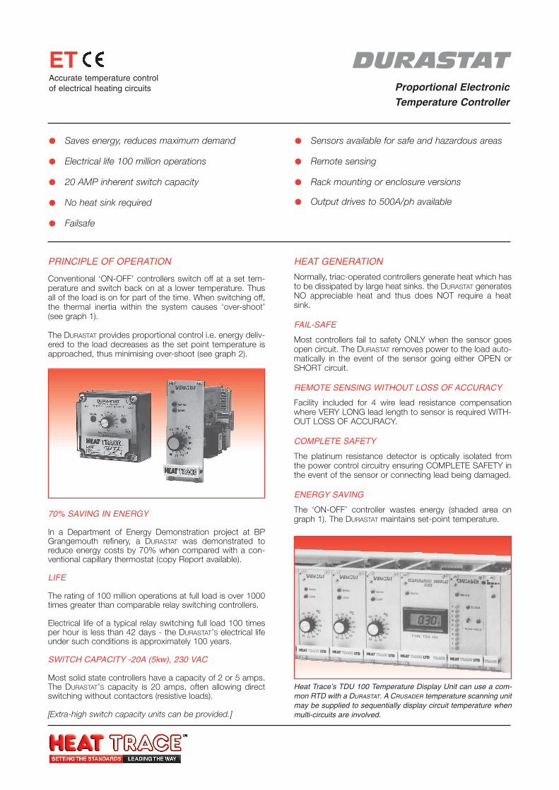
DURASTATProportional ElectronicTemperature Controller
ETAccurate temperature controlof electrical heating circuits
PRINCIPLE OF OPERATION
Conventional ‘ON-OFF’ controllers switch off at a set tem-perature and switch back on at a lower temperature. Thusall of the load is on for part of the time. When switching off,the thermal inertia within the system causes ‘over-shoot’(see graph 1).
The DURASTAT provides proportional control i.e. energy deliv-ered to the load decreases as the set point temperature isapproached, thus minimising over-shoot (see graph 2).
70% SAVING IN ENERGY
In a Department of Energy Demonstration project at BPGrangemouth refinery, a DURASTAT was demonstrated toreduce energy costs by 70% when compared with a con-ventional capillary thermostat (copy Report available).
LIFE
The rating of 100 million operations at full load is over 1000times greater than comparable relay switching controllers.
Electrical life of a typical relay switching full load 100 timesper hour is less than 42 days - the DURASTAT’S electrical lifeunder such conditions is approximately 100 years.
SWITCH CAPACITY -20A (5kw), 230 VAC
Most solid state controllers have a capacity of 2 or 5 amps.The DURASTAT’S capacity is 20 amps, often allowing directswitching without contactors (resistive loads).
[Extra-high switch capacity units can be provided.]
Saves energy, reduces maximum demand
Electrical life 100 million operations
20 AMP inherent switch capacity
No heat sink required
Failsafe
Sensors available for safe and hazardous areas
Remote sensing
Rack mounting or enclosure versions
Output drives to 500A/ph available
HEAT GENERATION
Normally, triac-operated controllers generate heat which hasto be dissipated by large heat sinks. the DURASTAT generatesNO appreciable heat and thus does NOT require a heatsink.
FAIL-SAFE
Most controllers fail to safety ONLY when the sensor goesopen circuit. The DURASTAT removes power to the load auto-matically in the event of the sensor going either OPEN orSHORT circuit.
REMOTE SENSING WITHOUT LOSS OF ACCURACY
Facility included for 4 wire lead resistance compensationwhere VERY LONG lead length to sensor is required WITH-OUT LOSS OF ACCURACY.
COMPLETE SAFETY
The platinum resistance detector is optically isolated fromthe power control circuitry ensuring COMPLETE SAFETY inthe event of the sensor or connecting lead being damaged.
ENERGY SAVING
The ‘ON-OFF’ controller wastes energy (shaded area ongraph 1). The DURASTAT maintains set-point temperature.
Heat Trace’s TDU 100 Temperature Display Unit can use a com-mon RTD with a DURASTAT. A CRUSADER temperature scanning unitmay be supplied to sequentially display circuit temperature whenmulti-circuits are involved.
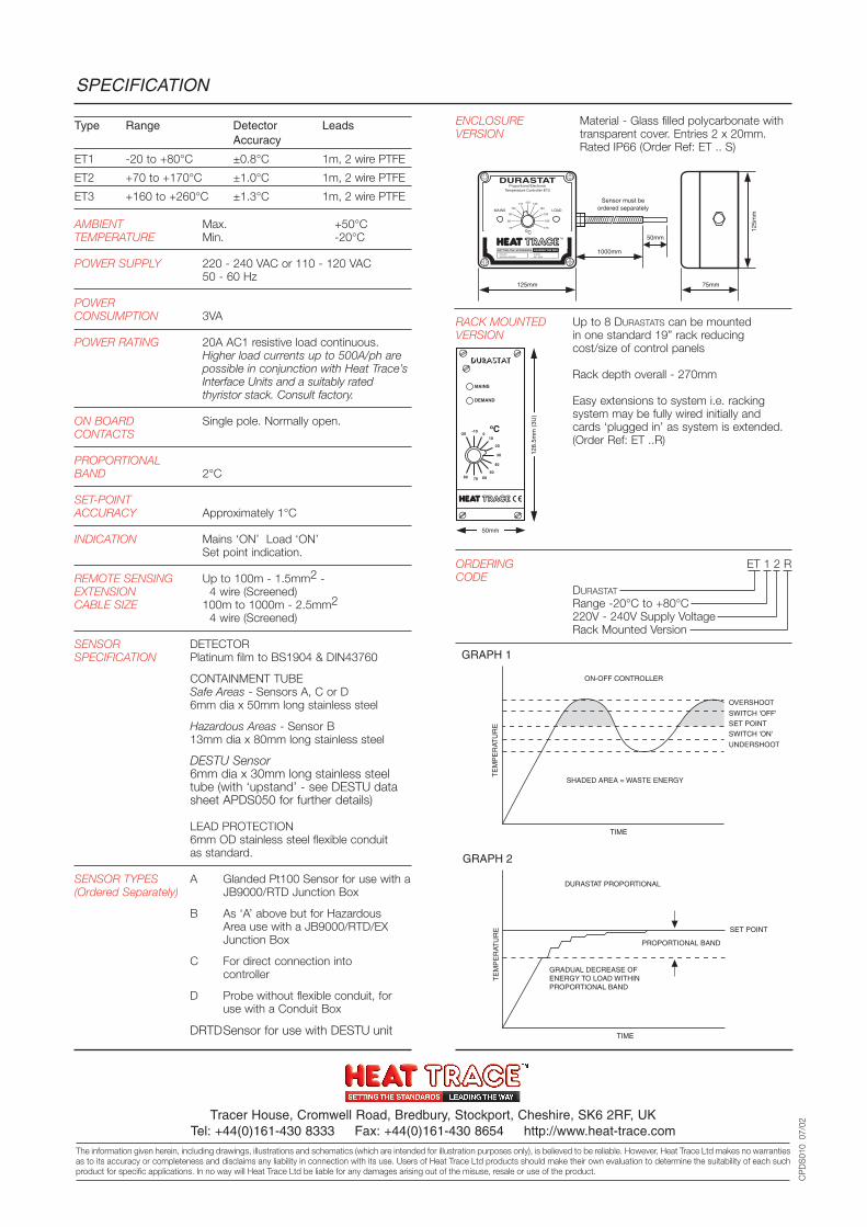
SPECIFICATION
CP
DS
010
07/
02
RACK MOUNTED Up to 8 DURASTATS can be mountedVERSION in one standard 19” rack reducing
cost/size of control panels
Rack depth overall - 270mm
Easy extensions to system i.e. rackingsystem may be fully wired initially andcards ‘plugged in’ as system is extended.(Order Ref: ET ..R)
ORDERING ET 1 2 RCODE
DURASTAT
Range -20°C to +80°C220V - 240V Supply VoltageRack Mounted Version
Type Range Detector LeadsAccuracy
ET1 -20 to +80°C ±0.8°C 1m, 2 wire PTFE
ET2 +70 to +170°C ±1.0°C 1m, 2 wire PTFE
ET3 +160 to +260°C ±1.3°C 1m, 2 wire PTFE
AMBIENT Max. +50°CTEMPERATURE Min. -20°C
POWER SUPPLY 220 - 240 VAC or 110 - 120 VAC 50 - 60 Hz
POWERCONSUMPTION 3VA
POWER RATING 20A AC1 resistive load continuous.Higher load currents up to 500A/ph arepossible in conjunction with Heat Trace’sInterface Units and a suitably rated thyristor stack. Consult factory.
ON BOARD Single pole. Normally open.CONTACTS
PROPORTIONAL BAND 2°C
SET-POINTACCURACY Approximately 1°C
INDICATION Mains ‘ON’ Load ‘ON’Set point indication.
REMOTE SENSING Up to 100m - 1.5mm2 -EXTENSION 4 wire (Screened)CABLE SIZE 100m to 1000m - 2.5mm2
4 wire (Screened)
SENSOR DETECTORSPECIFICATION Platinum film to BS1904 & DIN43760
CONTAINMENT TUBESafe Areas - Sensors A, C or D6mm dia x 50mm long stainless steel
Hazardous Areas - Sensor B13mm dia x 80mm long stainless steel
DESTU Sensor6mm dia x 30mm long stainless steel tube (with ‘upstand’ - see DESTU data sheet APDS050 for further details)
LEAD PROTECTION6mm OD stainless steel flexible conduitas standard.
SENSOR TYPES A Glanded Pt100 Sensor for use with a(Ordered Separately) JB9000/RTD Junction Box
B As ‘A’ above but for HazardousArea use with a JB9000/RTD/EXJunction Box
C For direct connection intocontroller
D Probe without flexible conduit, foruse with a Conduit Box
DRTDSensor for use with DESTU unit
ENCLOSURE Material - Glass filled polycarbonate withVERSION transparent cover. Entries 2 x 20mm.
Rated IP66 (Order Ref: ET .. S)
DURASTATProportional Electronic
Temperature Controller ET2
MAINS LOAD
oC
SETTING THE STANDARDS LEADING THE WAY
TM
125mm 75mm
125m
m
50mm
1000mm
Sensor must be ordered separately
70
80
90
100
110 130120
140
150
160
170
ISOLATE BEFORE OPENING
20 MAX 220 - 250V
MAINS
DEMAND
oC-20
-10 0
10
20
40
30
50 60 70 80
128.
5mm
(3U
)50mm
Tracer House, Cromwell Road, Bredbury, Stockport, Cheshire, SK6 2RF, UKTel: +44(0)161-430 8333 Fax: +44(0)161-430 8654 http://www.heat-trace.com
The information given herein, including drawings, illustrations and schematics (which are intended for illustration purposes only), is believed to be reliable. However, Heat Trace Ltd makes no warrantiesas to its accuracy or completeness and disclaims any liability in connection with its use. Users of Heat Trace Ltd products should make their own evaluation to determine the suitability of each suchproduct for specific applications. In no way will Heat Trace Ltd be liable for any damages arising out of the misuse, resale or use of the product.
SHADED AREA = WASTE ENERGY
TIME
ON-OFF CONTROLLER
GRAPH 1
TE
MP
ER
ATU
RE
OVERSHOOT
SWITCH 'OFF'SET POINTSWITCH 'ON'
UNDERSHOOT
GRADUAL DECREASE OF ENERGY TO LOAD WITHIN PROPORTIONAL BAND
TIME
DURASTAT PROPORTIONAL
GRAPH 2
TE
MP
ER
ATU
RE SET POINT
PROPORTIONAL BAND
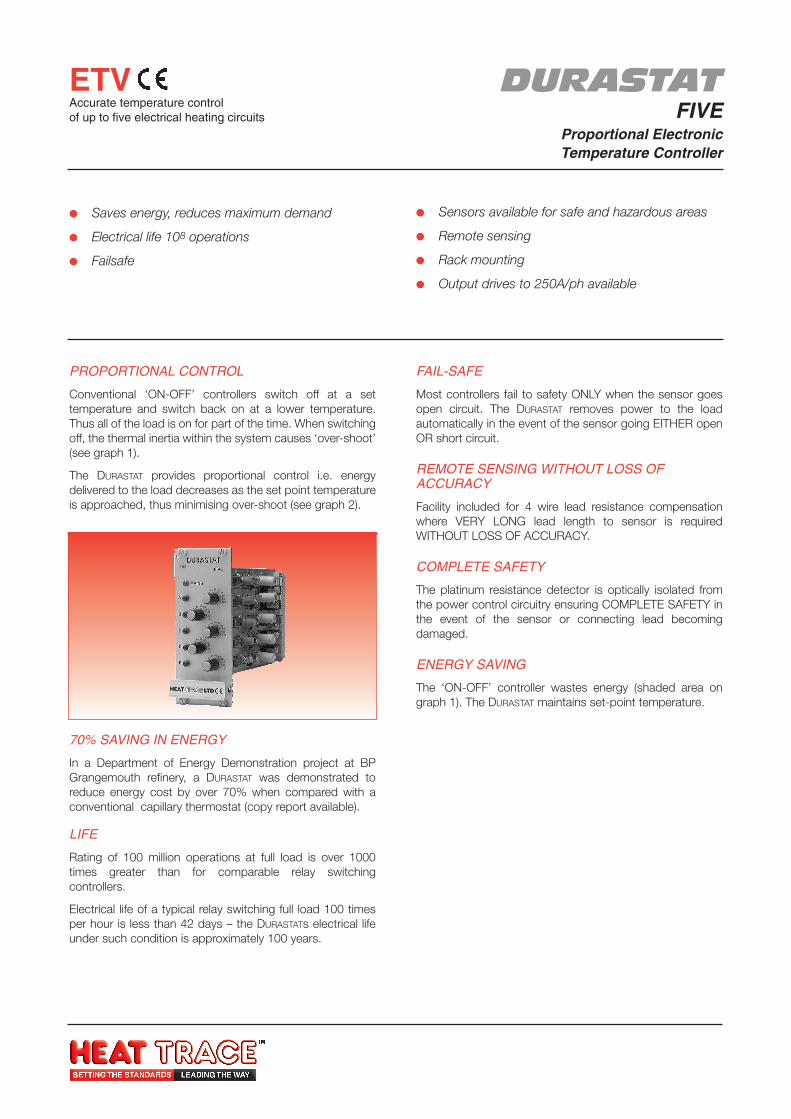
Saves energy, reduces maximum demand
Electrical life 108 operations
Failsafe
Sensors available for safe and hazardous areas
Remote sensing
Rack mounting
Output drives to 250A/ph available
PROPORTIONAL CONTROL
Conventional ‘ON-OFF’ controllers switch off at a settemperature and switch back on at a lower temperature.Thus all of the load is on for part of the time. When switchingoff, the thermal inertia within the system causes ‘over-shoot’(see graph 1).
The DURASTAT provides proportional control i.e. energydelivered to the load decreases as the set point temperatureis approached, thus minimising over-shoot (see graph 2).
DURASTATFIVE
Proportional ElectronicTemperature Controller
70% SAVING IN ENERGY
In a Department of Energy Demonstration project at BPGrangemouth refinery, a DURASTAT was demonstrated toreduce energy cost by over 70% when compared with aconventional capillary thermostat (copy report available).
LIFE
Rating of 100 million operations at full load is over 1000times greater than for comparable relay switchingcontrollers.
Electrical life of a typical relay switching full load 100 timesper hour is less than 42 days – the DURASTATs electrical lifeunder such condition is approximately 100 years.
FAIL-SAFE
Most controllers fail to safety ONLY when the sensor goesopen circuit. The DURASTAT removes power to the loadautomatically in the event of the sensor going EITHER openOR short circuit.
REMOTE SENSING WITHOUT LOSS OFACCURACY
Facility included for 4 wire lead resistance compensationwhere VERY LONG lead length to sensor is requiredWITHOUT LOSS OF ACCURACY.
COMPLETE SAFETY
The platinum resistance detector is optically isolated fromthe power control circuitry ensuring COMPLETE SAFETY inthe event of the sensor or connecting lead becomingdamaged.
ENERGY SAVING
The ‘ON-OFF’ controller wastes energy (shaded area ongraph 1). The DURASTAT maintains set-point temperature.
ETVAccurate temperature controlof up to five electrical heating circuits
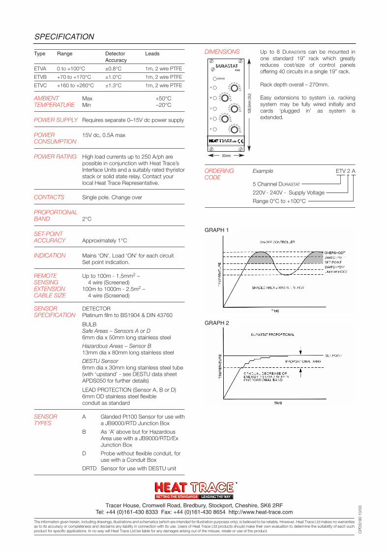
SPECIFICATION
DIMENSIONS Up to 8 DURASTATs can be mounted inone standard 19” rack which greatlyreduces cost/size of control panelsoffering 40 circuits in a single 19” rack.
Rack depth overall – 270mm.
Easy extensions to system i.e. rackingsystem may be fully wired initially andcards ‘plugged in’ as system isextended.
ORDERING Example ETV 2 ACODE
5 Channel DURASTAT
220V - 240V - Supply Voltage
Range 0°C to +100°C
50mm
128.
5mm
(3U)
GRAPH 1
GRAPH 2
CP
DS
180
10/0
3Tracer House, Cromwell Road, Bredbury, Stockport, Cheshire, SK6 2RFTel: +44 (0)161-430 8333 Fax: +44 (0)161-430 8654 http://www.heat-trace.com
The information given herein, including drawings, illustrations and schematics (which are intended for illustration purposes only), is believed to be reliable. However, Heat Trace Ltd makes no warrantiesas to its accuracy or completeness and disclaims any liability in connection with its use. Users of Heat Trace Ltd products should make their own evaluation to determine the suitability of each suchproduct for specific applications. In no way will Heat Trace Ltd be liable for any damages arising out of the misuse, resale or use of the product.
Type Range Detector LeadsAccuracy
ETVA 0 to +100°C ±0.8°C 1m, 2 wire PTFE
ETVB +70 to +170°C ±1.0°C 1m, 2 wire PTFE
ETVC +160 to +260°C ±1.3°C 1m, 2 wire PTFE
AMBIENT Max +50°CTEMPERATURE Min –20°C
POWER SUPPLY Requires separate 0–15V dc power supply
POWER 15V dc, 0.5A maxCONSUMPTION
POWER RATING High load currents up to 250 A/ph arepossible in conjunction with Heat Trace’sInterface Units and a suitably rated thyristor stack or solid state relay. Contact your local Heat Trace Representative.
CONTACTS Single pole. Change over
PROPORTIONALBAND 2°C
SET-POINTACCURACY Approximately 1°C
INDICATION Mains ‘ON’. Load ‘ON’ for each circuitSet point indication.
REMOTE Up to 100m - 1.5mm2 –SENSING 4 wire (Screened)EXTENSION 100m to 1000m - 2.5m2 –CABLE SIZE 4 wire (Screened)
SENSOR DETECTORSPECIFICATION Platinum film to BS1904 & DIN 43760
BULBSafe Areas – Sensors A or D6mm dia x 50mm long stainless steel
Hazardous Areas – Sensor B13mm dia x 80mm long stainless steel
DESTU Sensor6mm dia x 30mm long stainless steel tube (with ‘upstand’ - see DESTU data sheet APDS050 for further details)
LEAD PROTECTION (Sensor A, B or D)6mm OD stainless steel flexibleconduit as standard
SENSOR A Glanded Pt100 Sensor for use with TYPES a JB9000/RTD Junction Box
B As ‘A’ above but for HazardousArea use with a JB9000/RTD/ExJunction Box
D Probe without flexible conduit, foruse with a Conduit Box
DRTD Sensor for use with DESTU unit

CENTURIONProportional ElectronicTemperature Controller
MSAccurate temperature controlof electrical heating circuitswith high and low alarm functions
PROPORTIONAL CONTROL
Conventional ‘ON-OFF’ controllers switch off at a settemperature and switch back on at a lower temperature.Thus, all of the load is on for part of the time. When switchingoff, the thermal inertia within the system causes ‘over-shoot’(see graph 1).
The Centurion provides proportional control ie. energydelivered to the load decreases as the set-point isapproached, thus minimising over-shoot (see graph 2).
Saves energy, reduces maximum demand
Electrical life 108 operations
30 AMP inherent switch capacity
No heat sink required
Sensors available for safe and hazardous areas
Remote sensing
Three wide temperature ranges
Output drives up to 250A/ph available
Switch Capacity – 30A (7kw approx.), 230V
Most solid state controllers have a capacity of 5 or 8 amps.The Centurion’s capacity is 30A – the limit is on the terminals,not the contacts. Also has facility via “Aux” to drive up to3 Solid State Relays or 3 Thyristor Interface units for highpower loads.
Heat Generation
Normally, triac-operated controllers generate heat which hasto be dissipated by large heat sinks. The Centurion generatesNO appreciable heat and thus does NOT require a heat sink.
High / Low Temperature Alarms
Local independent high and low temperature alarm indica-tion is provided with internal relays for separate high/lowremote alarms.
Remote Sensing without loss of acuracy
Facility included for 4 wire lead resistance compensationwhere VERY LONG lead length to sensor is requiredWITHOUT LOSS OF ACCURACY.
Complete Safety
The platinum resistance detector is optically isolated fromthe power control circuitry ensuring COMPLETE SAFETY inthe event of the sensor or connecting lead becomingdamaged.
Reduces Maximum Demand
Once up to set-point temperature, the Centurion deliversonly sufficient energy required to maintain this temperature.
Multi-Circuit Temperature Display
Heat Trace’s TDU100 Temperature Display Unit may beprovided utilising an RTD in common with the Centurion. ACrusader temperature scanning unit may be supplied tosequentially display circuit temperature when multi-circuitsare involved.
FEATURES
70% Energy Savings
In a Department of Energy Demonstration at BP Grangemouthrefinery, a Heat Trace proportional temperature controller wasdemonstrated to reduce energy costs by over 70% whencompared with a conventional capillary thermostat (copyReport available).
Life
Ratings of 100 million operations at full load is over 1000times greater than for comparable relay switching controllers.
Electrical life of a typical relay switching full load 100 timesper hour is less than 42 days – the Centurion’s electrial lifeunder such conditions is approximately 100 years.
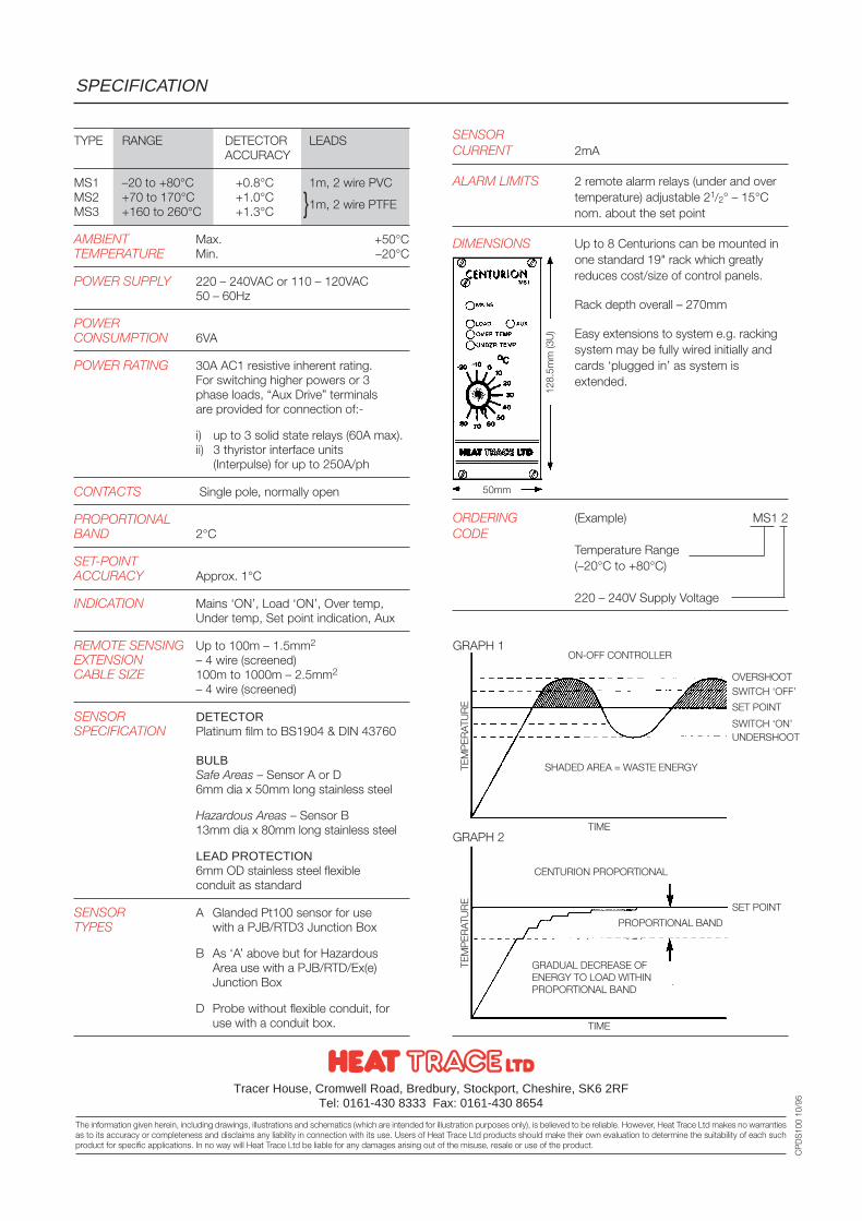
TYPE RANGE DETECTOR LEADSACCURACY
MS1 –20 to +80°C +0.8°C 1m, 2 wire PVCMS2 +70 to 170°C +1.0°C 1m, 2 wire PTFEMS3 +160 to 260°C +1.3°C
AMBIENT Max. +50°CTEMPERATURE Min. –20°C
POWER SUPPLY 220 – 240VAC or 110 – 120VAC50 – 60Hz
POWERCONSUMPTION 6VA
POWER RATING 30A AC1 resistive inherent rating.For switching higher powers or 3phase loads, “Aux Drive” terminalsare provided for connection of:-
i) up to 3 solid state relays (60A max).ii) 3 thyristor interface units
(Interpulse) for up to 250A/ph
CONTACTS Single pole, normally open
PROPORTIONALBAND 2°C
SET-POINTACCURACY Approx. 1°C
INDICATION Mains ‘ON’, Load ‘ON’, Over temp,Under temp, Set point indication, Aux
REMOTE SENSING Up to 100m – 1.5mm2
EXTENSION – 4 wire (screened)CABLE SIZE 100m to 1000m – 2.5mm2
– 4 wire (screened)
SENSOR DETECTORSPECIFICATION Platinum film to BS1904 & DIN 43760
BULBSafe Areas – Sensor A or D6mm dia x 50mm long stainless steel
Hazardous Areas – Sensor B13mm dia x 80mm long stainless steel
LEAD PROTECTION6mm OD stainless steel flexibleconduit as standard
SENSOR A Glanded Pt100 sensor for useTYPES with a PJB/RTD3 Junction Box
B As ‘A’ above but for HazardousArea use with a PJB/RTD/Ex(e)Junction Box
D Probe without flexible conduit, for use with a conduit box.
SENSORCURRENT 2mA
ALARM LIMITS 2 remote alarm relays (under and overtemperature) adjustable 21/2° – 15°Cnom. about the set point
DIMENSIONS Up to 8 Centurions can be mounted inone standard 19" rack which greatlyreduces cost/size of control panels.
Rack depth overall – 270mm
Easy extensions to system e.g. rackingsystem may be fully wired initially andcards ‘plugged in’ as system isextended.
ORDERING (Example) MS1 2CODE
Temperature Range(–20°C to +80°C)
220 – 240V Supply Voltage
GRAPH 1
GRAPH 2
SPECIFICATION
Tracer House, Cromwell Road, Bredbury, Stockport, Cheshire, SK6 2RFTel: 0161-430 8333 Fax: 0161-430 8654
The information given herein, including drawings, illustrations and schematics (which are intended for illustration purposes only), is believed to be reliable. However, Heat Trace Ltd makes no warrantiesas to its accuracy or completeness and disclaims any liability in connection with its use. Users of Heat Trace Ltd products should make their own evaluation to determine the suitability of each suchproduct for specific applications. In no way will Heat Trace Ltd be liable for any damages arising out of the misuse, resale or use of the product.
CP
DS
100
10/9
5
50mm
128.
5mm
(3U
)
OVERSHOOTSWITCH ‘OFF’
SET POINT
SWITCH ‘ON’UNDERSHOOT
SET POINT
SHADED AREA = WASTE ENERGY
GRADUAL DECREASE OFENERGY TO LOAD WITHINPROPORTIONAL BAND
TIME
TIME
TEM
PER
ATU
RE
TEM
PER
ATU
RE
ON-OFF CONTROLLER
CENTURION PROPORTIONAL
PROPORTIONAL BAND
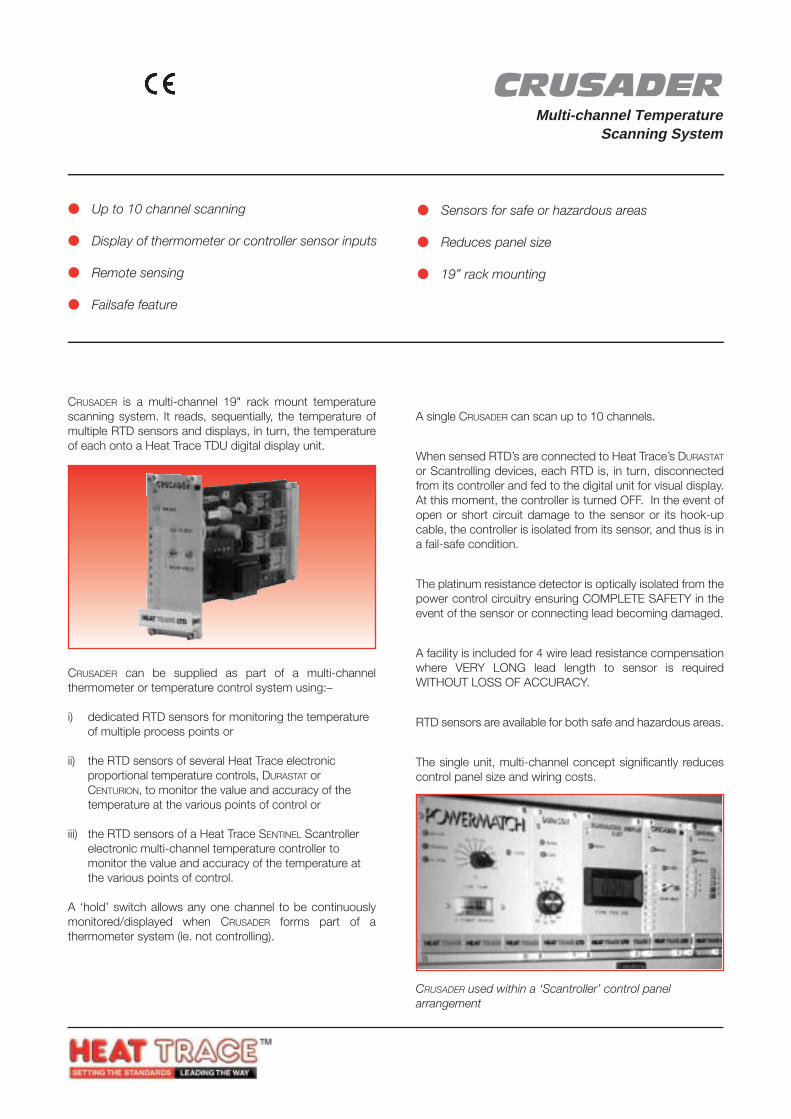
CRUSADERMulti-channel Temperature
Scanning System
CRUScans the temperature ofmultiple RTD sensorsfor sequential display
SYSTEM DESCRIPTION
CRUSADER is a multi-channel 19" rack mount temperaturescanning system. It reads, sequentially, the temperature ofmultiple RTD sensors and displays, in turn, the temperatureof each onto a Heat Trace TDU digital display unit.
Up to 10 channel scanning
Display of thermometer or controller sensor inputs
Remote sensing
Failsafe feature
Sensors for safe or hazardous areas
Reduces panel size
19” rack mounting
FEATURES
Multi-channel scanningA single CRUSADER can scan up to 10 channels.
Fail-Safe featureWhen sensed RTD’s are connected to Heat Trace’s DURASTAT
or Scantrolling devices, each RTD is, in turn, disconnectedfrom its controller and fed to the digital unit for visual display.At this moment, the controller is turned OFF. In the event ofopen or short circuit damage to the sensor or its hook-upcable, the controller is isolated from its sensor, and thus is ina fail-safe condition.
Complete SafetyThe platinum resistance detector is optically isolated from thepower control circuitry ensuring COMPLETE SAFETY in theevent of the sensor or connecting lead becoming damaged.
Remote sensing without loss of accuracyA facility is included for 4 wire lead resistance compensationwhere VERY LONG lead length to sensor is requiredWITHOUT LOSS OF ACCURACY.
Safe/Hazardous AreasRTD sensors are available for both safe and hazardous areas.
Reduced Panel SizeThe single unit, multi-channel concept significantly reducescontrol panel size and wiring costs.
CRUSADER can be supplied as part of a multi-channelthermometer or temperature control system using:–
i) dedicated RTD sensors for monitoring the temperatureof multiple process points or
ii) the RTD sensors of several Heat Trace electronicproportional temperature controls, DURASTAT orCENTURION, to monitor the value and accuracy of thetemperature at the various points of control or
iii) the RTD sensors of a Heat Trace SENTINEL Scantrollerelectronic multi-channel temperature controller tomonitor the value and accuracy of the temperature atthe various points of control.
A ‘hold’ switch allows any one channel to be continuouslymonitored/displayed when CRUSADER forms part of athermometer system (ie. not controlling).
CRUSADER used within a ‘Scantroller’ control panelarrangement
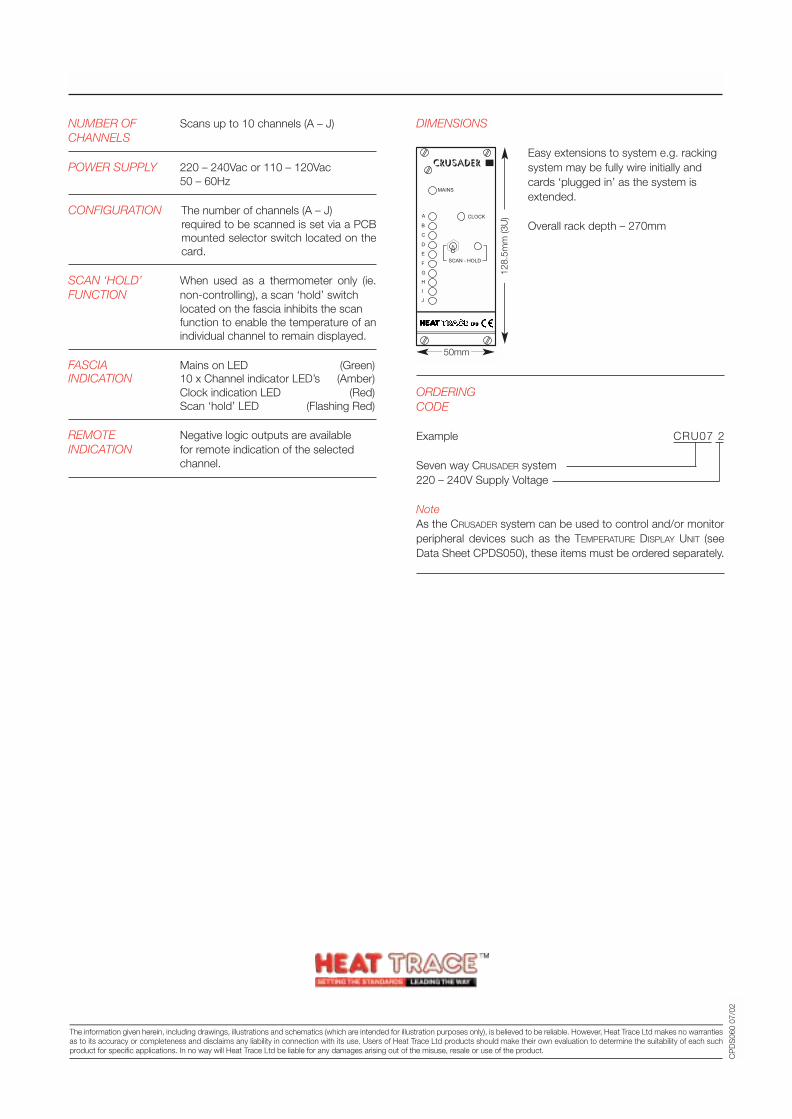
NUMBER OF Scans up to 10 channels (A – J)CHANNELS
POWER SUPPLY 220 – 240Vac or 110 – 120Vac50 – 60Hz
CONFIGURATION The number of channels (A – J) required to be scanned is set via a PCBmounted selector switch located on thecard.
SCAN ‘HOLD’ When used as a thermometer only (ie.FUNCTION non-controlling), a scan ‘hold’ switch
located on the fascia inhibits the scan function to enable the temperature of anindividual channel to remain displayed.
FASCIA Mains on LED (Green)INDICATION 10 x Channel indicator LED’s (Amber)
Clock indication LED (Red)Scan ‘hold’ LED (Flashing Red)
REMOTE Negative logic outputs are availableINDICATION for remote indication of the selected
channel.
DIMENSIONS
Easy extensions to system e.g. rackingsystem may be fully wire initially andcards ‘plugged in’ as the system isextended.
Overall rack depth – 270mm
ORDERINGCODE
Example CRU07 2
Seven way CRUSADER system220 – 240V Supply Voltage
NoteAs the CRUSADER system can be used to control and/or monitorperipheral devices such as the TEMPERATURE DISPLAY UNIT (seeData Sheet CPDS050), these items must be ordered separately.
SPECIFICATION
CP
DS
060
07/0
2
50mm
128.
5mm
(3U
)
Tracer House, Cromwell Road, Bredbury, Stockport, Cheshire, SK6 2RF, UKTel: +44(0)161-430 8333 Fax: +44(0)161-430 8654 http://www.heat-trace.com
The information given herein, including drawings, illustrations and schematics (which are intended for illustration purposes only), is believed to be reliable. However, Heat Trace Ltd makes no warrantiesas to its accuracy or completeness and disclaims any liability in connection with its use. Users of Heat Trace Ltd products should make their own evaluation to determine the suitability of each suchproduct for specific applications. In no way will Heat Trace Ltd be liable for any damages arising out of the misuse, resale or use of the product.
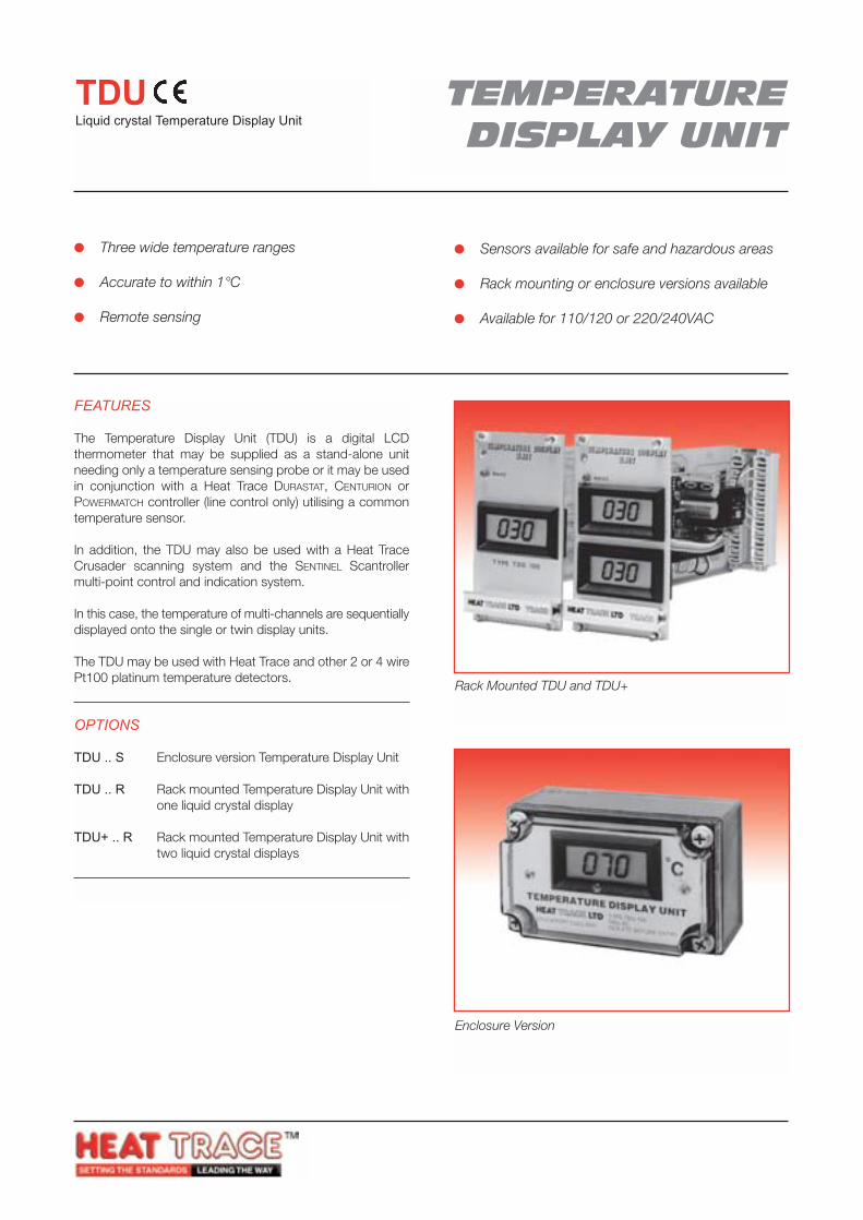
Enclosure Version
Rack Mounted TDU and TDU+
TEMPERATUREDISPLAY UNIT
TDULiquid crystal Temperature Display Unit
FEATURES
The Temperature Display Unit (TDU) is a digital LCDthermometer that may be supplied as a stand-alone unitneeding only a temperature sensing probe or it may be usedin conjunction with a Heat Trace DURASTAT, CENTURION orPOWERMATCH controller (line control only) utilising a commontemperature sensor.
In addition, the TDU may also be used with a Heat TraceCrusader scanning system and the SENTINEL Scantrollermulti-point control and indication system.
In this case, the temperature of multi-channels are sequentiallydisplayed onto the single or twin display units.
The TDU may be used with Heat Trace and other 2 or 4 wirePt100 platinum temperature detectors.
OPTIONS
TDU .. S Enclosure version Temperature Display Unit
TDU .. R Rack mounted Temperature Display Unit withone liquid crystal display
TDU+ .. R Rack mounted Temperature Display Unit withtwo liquid crystal displays
Three wide temperature ranges
Accurate to within 1°C
Remote sensing
Sensors available for safe and hazardous areas
Rack mounting or enclosure versions available
Available for 110/120 or 220/240VAC

Type Range Detector LeadsAccuracy
TDU..1 –20 to +80°C +0.8°C 1m, 2 wire PVC
TDU..2 +70 to 170°C +1.0°C 1m, 2 wire PTFE
TDU..3 +160 to 260°C +1.3°C 1m, 2 wire PTFE
AMBIENT Maximum +50°CTEMPERATURE Minimum 0°C
POWER SUPPLY 110 – 120V or 220 – 240VAC
DISPLAY 31/2 digit x 0.5" high
UNIT ACCURACY Within 1°C
SENSOR DETECTORSPECIFICATION Platinum film to BS1904 & DIN43760
BULBSafe Areas – Sensor A or D6mm dia x 50mm long stainless steelHazardous Areas – Sensor B13mm dia x 80mm long stainless steel
LEAD PROTECTION6mm OD Stainless Steel flexibleconduit as standard
SENSOR TYPES A Glanded Pt100 sensor for usewith a PJB/RTD/3 junction box
B As ‘A’ above but for hazardousarea use with a PJB/RTD/Ex(e)junction box.
D Probe without flexible conduitfor use with a conduit box.
SENSORCURRENT < 4mA
ORDERINGCODE
Example TDU+21R
Temperature Display UnitTwo liquid crystal displays *220 – 240VAC Supply voltageRange –20 to +80°CRack mounted
* Twin LCD unit only available in rack mount version
SPECIFICATION
CP
DS
050
05/0
3
ENCLOSURE VERSION
RACK MOUNTED VERSIONS
TEMPERATURE DISPLAY UNIT
Co
STOCKPORT, ENGLAND
TYPE TDU 100
ISOLATE BEFORE ENTRY230v AC
70mm 70mm
75mm
125mm
75m
m
128.
5mm
(3U
)
MAINS
TEMPERATURE DISPLAYUNIT
TYPE TDU 100
MAINS
TEMPERATURE DISPLAYUNIT+
GROUP TDU
GROUP TDU
Tracer House, Cromwell Road, Bredbury, Stockport, Cheshire, SK6 2RF, UKTel: +44(0)161-430 8333 Fax: +44(0)161-430 8654 http://www.heat-trace.com
The information given herein, including drawings, illustrations and schematics (which are intended for illustration purposes only), is believed to be reliable. However, Heat Trace Ltd makes no warrantiesas to its accuracy or completeness and disclaims any liability in connection with its use. Users of Heat Trace Ltd products should make their own evaluation to determine the suitability of each suchproduct for specific applications. In no way will Heat Trace Ltd be liable for any damages arising out of the misuse, resale or use of the product.
030
030030
030
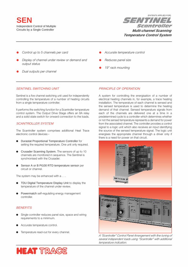
SENTINELScantroller
Multi-channel ScanningTemperature Control System
SENIndependent Control of MultipleCircuits by a Single Controller
SENTINEL SWITCHING UNIT
Sentinel is a five channel switching unit used for independentlycontrolling the temperature of a number of heating circuitsfrom a single temperature controller.
It performs the switching function for a Scantroller temperaturecontrol system. The Output Drive Stage offers an 8A relayand a solid state switch for onward connection to the loads.
SCANTROLLER SYSTEM
The Scantroller system comprises additional Heat Traceelectronic control devices:–
Durastat Proportional Temperature Controller forsetting the required temperature. One unit only required.
Crusader Scanning System. The sensors of up to 10channels are monitored in sequence. The Sentinel issynchronised with the Crusader.
Sensor A or B Pt100 RTD temperature sensor percircuit or channel.
The system may be enhanced with a . . .
TDU Digital Temperature Display Unit to display thetemperature of the channel under review.
Powermatch self-regulating energy managementcontroller.
BENEFITS
Single controller reduces panel size, space and wiringrequirements to a minimum.
Accurate temperature control.
Temperature read-out for every channel.
Control up to 5 channels per card
Display of channel under review or demand andoutput status
Dual outputs per channel
Accurate temperature control
Reduces panel size
19” rack mounting
PRINCIPLE OF OPERATION
A system for controlling the energisation of a number ofelectrical heating channels in, for example, a trace heatinginstallation. The temperature of each channel is sensed andthe sensed temperature is used to determine the heatingdemand of that channel. Sensed temperature signals fromeach of the channels are delivered one at a time in apredetermined cycle to a controller which determines whetheror not the sensed temperature represents a demand for powerfrom the associated channel. The controller provides a controlsignal to a logic unit which also receives an input identifyingthe source of the sensed temperature signal. The logic unitenergises the appropriate channel through a driver only ifthere is a need for power on that circuit.
A “Scantroller” Control Panel Arrangement with fine tuning ofseveral independent loads using “Scantroller” with additionaltemperature indication.
(PATENTS APPLIED FOR)
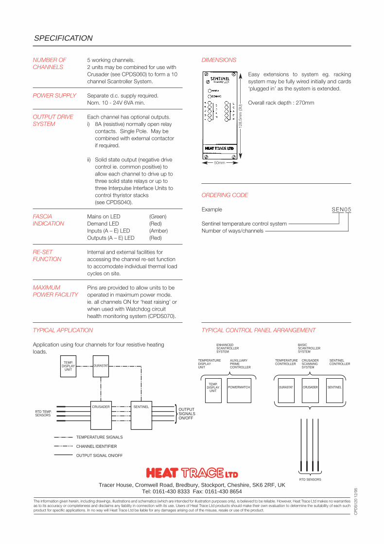
NUMBER OF 5 working channels.CHANNELS 2 units may be combined for use with
Crusader (see CPDS060) to form a 10 channel Scantroller System.
POWER SUPPLY Separate d.c. supply required.Nom. 10 - 24V 6VA min.
OUTPUT DRIVE Each channel has optional outputs.SYSTEM i) 8A (resistive) normally open relay
contacts. Single Pole. May becombined with external contactorif required.
ii) Solid state output (negative drivecontrol ie. common positive) toallow each channel to drive up tothree solid state relays or up tothree Interpulse Interface Units tocontrol thyristor stacks(see CPDS040).
FASCIA Mains on LED (Green)INDICATION Demand LED (Red)
Inputs (A – E) LED (Amber)Outputs (A – E) LED (Red)
RE-SET Internal and external facilities forFUNCTION accessing the channel re-set function
to accomodate individual thermal loadcycles on site.
MAXIMUM Pins are provided to allow units to bePOWER FACILITY operated in maximum power mode.
ie. all channels ON for ‘heat raising’ orwhen used with Watchdog circuithealth monitoring system (CPDS070).
TYPICAL APPLICATION
Application using four channels for four resistive heatingloads.
DIMENSIONS
Easy extensions to system eg. rackingsystem may be fully wired initially and cards‘plugged in’ as the system is extended.
Overall rack depth : 270mm
ORDERING CODE
Example SEN05
Sentinel temperature control systemNumber of ways/channels
TYPICAL CONTROL PANEL ARRANGEMENT
SPECIFICATION
Tracer House, Cromwell Road, Bredbury, Stockport, Cheshire, SK6 2RF, UKTel: 0161-430 8333 Fax: 0161-430 8654
The information given herein, including drawings, illustrations and schematics (which are intended for illustration purposes only), is believed to be reliable. However, Heat Trace Ltd makes no warrantiesas to its accuracy or completeness and disclaims any liability in connection with its use. Users of Heat Trace Ltd products should make their own evaluation to determine the suitability of each suchproduct for specific applications. In no way will Heat Trace Ltd be liable for any damages arising out of the misuse, resale or use of the product.
CP
DS
120
12/9
5
50mm
128.
5mm
(3U
)
TEMP.DISPLAY
UNIT
DURASTAT
CRUSADER SENTINELRTD TEMP.SENSORS
OUTPUTSIGNALSON/OFF
TEMPERATURE SIGNALS
CHANNEL IDENTIFIER
OUTPUT SIGNAL ON/OFF
TEMP.DISPLAY
UNITPOWERMATCH DURASTAT CRUSADER SENTINEL
SENTINELCONTROLLER
CRUSADERSCANNINGSYSTEM
TEMPERATURECONTROLLER
BASICSCANTROLLERSYSTEM
TEMPERATUREDISPLAYUNIT
ENHANCEDSCANTROLLERSYSTEM
AUXILLIARYPRIMECONTROLLER
RTD SENSORS

MONITOHM(PATENTED)
Circuit Resistance Monitor
MONMonitors the resistance of ElectricallyHeat Traced Constant Wattage circuits
APPLICATION
The MONITOHM is ideal for the monitoring of linear resistivecircuits but especially constant wattage heat tracing circuits.Certain installations, particularly freeze protectionapplications, are de-energised for long periods. Without amonitor, faults which may develop only become knownwhen the process fails.
The MONITOHM detects the fault immediately it occurs andalarms before the process is affected. It can also be used toautomatically change over to standby heater if required.
OPERATION
The MONITOHM monitors the resistance value of any linearresistive load whether energised or not. An alarm condition isindicated if the load resistance changes by more than a pre-set amount. Thus, the MONITOHM will also detect a resistivefault which would not normally blow a fuse but could impairthe operation of the load.
Constant surveillance whether load isenergised or not
Alarm initiated on change in load resistance
Power failure detection
Adjustable sensitivity
Test facility
Facility for automatic switching to auxiliarycircuits
Remote sensing
Local or remote/panel mounting
OTHER FEATURES:
Alarms
The unit has a built-in LED alarm indicator and a relay forremote indication.
Power Failure Alarm
When a separate supply is provided (see sketch overleaf), aremote alarm is raised should the supply to the MONITOHM(which is the same supply as for the load) fail. eg. a blownfuse. The alarm relay may also be used to supply a back-upheater.
Adjustable Sensitivity
The unit’s sensitivity to change of resistance can be variedover a range of 6% to 40%. The alarm condition is raised ifthe load resistance varies by more than the sensitivitysetting chosen.
Ease of Setting Up
The unit is set up by adjusting two potentiometers (one forenergised, the other for de-energised states). A standardhigh impedance multimeter (dvm) is needed. The sensitivityis then set to the desired level. Simple site setting-upprocedures are provided with each unit.
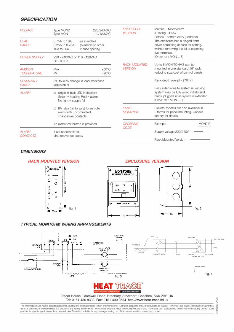
INTERNAL WIRING
HEATER(S)
STAT SENSOR
COMBI/CT-A BOX 4 CORE LOAD SIDE
N
N
L
L
'MONITOHM' UNIT
SWITCHED LINE
2 CORE
240 V (16A MAX)
SUPPLY SIDE
SPECIFICATION
Tracer House, Cromwell Road, Bredbury, Stockport, Cheshire, SK6 2RF, UKTel: 0161-430 8333 Fax: 0161-430 8654 http://www.heat-trace.ltd.uk
The information given herein, including drawings, illustrations and schematics (which are intended for illustration purposes only), is believed to be reliable. However, Heat Trace Ltd makes no warrantiesas to its accuracy or completeness and disclaims any liability in connection with its use. Users of Heat Trace Ltd products should make their own evaluation to determine the suitability of each suchproduct for specific applications. In no way will Heat Trace Ltd be liable for any damages arising out of the misuse, resale or use of the product.
CP
DS
020
01/9
8
ENCLOSURE Material - Macrolon™VERSION IP rating - IP557
Entries - bottom entry (undrilled)The enclosure has a hinged front cover permitting access for setting,without removing the lid or exposinglive terminals.(Order ref : MON .. S)
RACK MOUNTED Up to 8 MONITOHMS can beVERSION mounted in one standard 19” rack,
reducing size/cost of control panels.
Rack depth overall - 270mm
Easy extensions to system ie. rackingsystem may be fully wired initially andcards ‘plugged in’ as system is extended.(Order ref : MON .. R)
PANEL Skeletal models are also available inMOUNTING 2 forms for panel mounting. Consult
factory for details.
ORDERING Example MON2 RCODE
Supply voltage 220/240V
Rack Mounted Version
VOLTAGE Type MON2 220/240VACType MON1 110/120VAC
LOAD 0.75A to 16A as standardRANGE 0.25A to 0.76A (Available to order.
16A to 30A Please specify)
POWER SUPPLY 220 - 240VAC or 110 - 120VAC50 - 60 Hz
AMBIENT Max. +50°CTEMPERATURE Min. -20°C
SENSITIVITY 6% to 40% change in load resistanceRANGE (adjustable)
ALARM a) single in-built LED indication:Green = healthy, Red = alarm,No light = supply fail
b) 8A relay (fail to safe) for remotealarm with uncommitted changeover contacts.
An alarm test button is provided
ALARM 1 set uncommittedCONTACTS changeover contacts.
RACK MOUNTED VERSION ENCLOSURE VERSION
DIMENSIONS
TYPICAL MONITOHM WIRING ARRANGEMENTS
fig. 1
fig. 3fig. 4
fig. 2
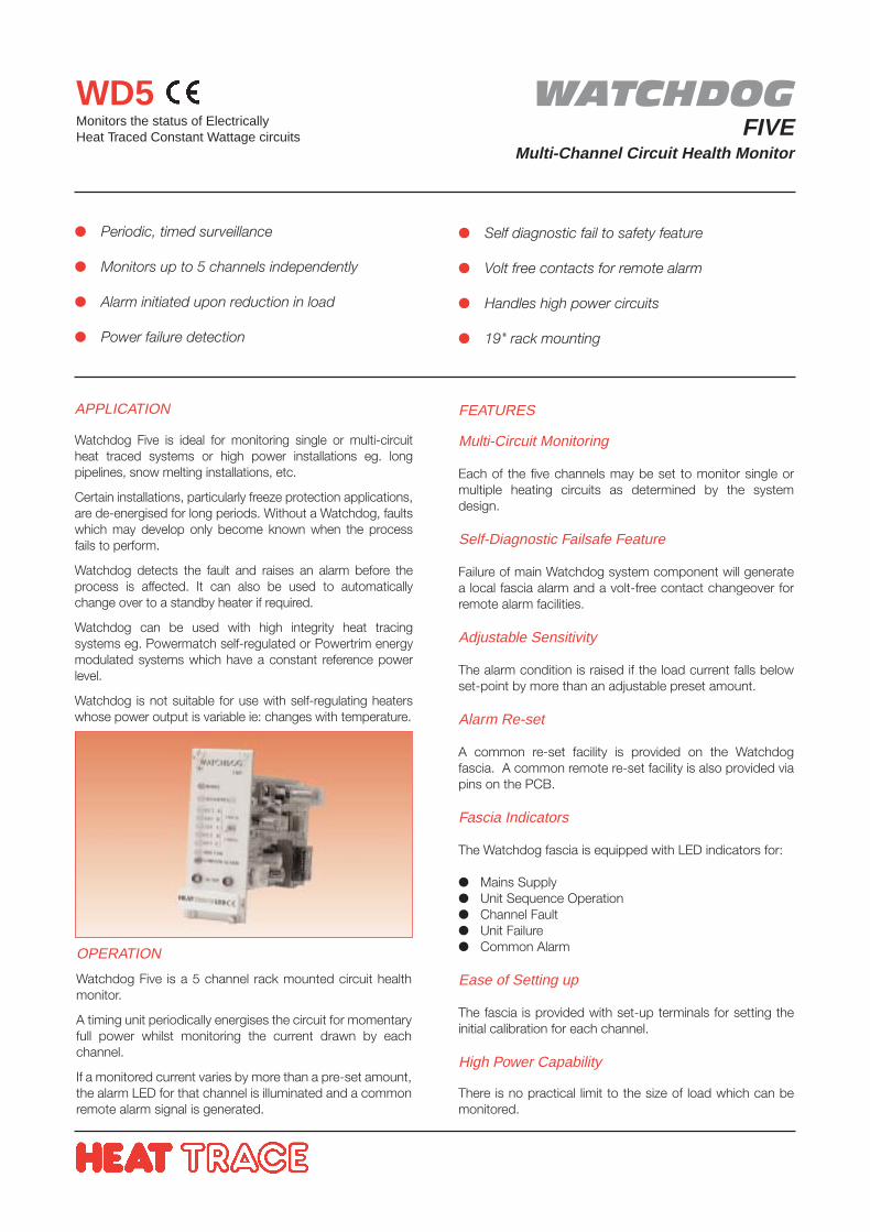
WATCHDOGFIVE
Multi-Channel Circuit Health Monitor
WD5Monitors the status of ElectricallyHeat Traced Constant Wattage circuits
APPLICATION
Watchdog Five is ideal for monitoring single or multi-circuitheat traced systems or high power installations eg. longpipelines, snow melting installations, etc.
Certain installations, particularly freeze protection applications,are de-energised for long periods. Without a Watchdog, faultswhich may develop only become known when the processfails to perform.
Watchdog detects the fault and raises an alarm before theprocess is affected. It can also be used to automaticallychange over to a standby heater if required.
Watchdog can be used with high integrity heat tracingsystems eg. Powermatch self-regulated or Powertrim energymodulated systems which have a constant reference powerlevel.
Watchdog is not suitable for use with self-regulating heaterswhose power output is variable ie: changes with temperature.
Periodic, timed surveillance
Monitors up to 5 channels independently
Alarm initiated upon reduction in load
Power failure detection
Self diagnostic fail to safety feature
Volt free contacts for remote alarm
Handles high power circuits
19" rack mounting
OPERATION
Watchdog Five is a 5 channel rack mounted circuit healthmonitor.
A timing unit periodically energises the circuit for momentaryfull power whilst monitoring the current drawn by eachchannel.
If a monitored current varies by more than a pre-set amount,the alarm LED for that channel is illuminated and a commonremote alarm signal is generated.
FEATURES
Multi-Circuit Monitoring
Each of the five channels may be set to monitor single ormultiple heating circuits as determined by the systemdesign.
Self-Diagnostic Failsafe Feature
Failure of main Watchdog system component will generatea local fascia alarm and a volt-free contact changeover forremote alarm facilities.
Adjustable Sensitivity
The alarm condition is raised if the load current falls belowset-point by more than an adjustable preset amount.
Alarm Re-set
A common re-set facility is provided on the Watchdogfascia. A common remote re-set facility is also provided viapins on the PCB.
Fascia Indicators
The Watchdog fascia is equipped with LED indicators for:
Mains Supply Unit Sequence Operation Channel Fault Unit Failure Common Alarm
Ease of Setting up
The fascia is provided with set-up terminals for setting theinitial calibration for each channel.
High Power Capability
There is no practical limit to the size of load which can bemonitored.
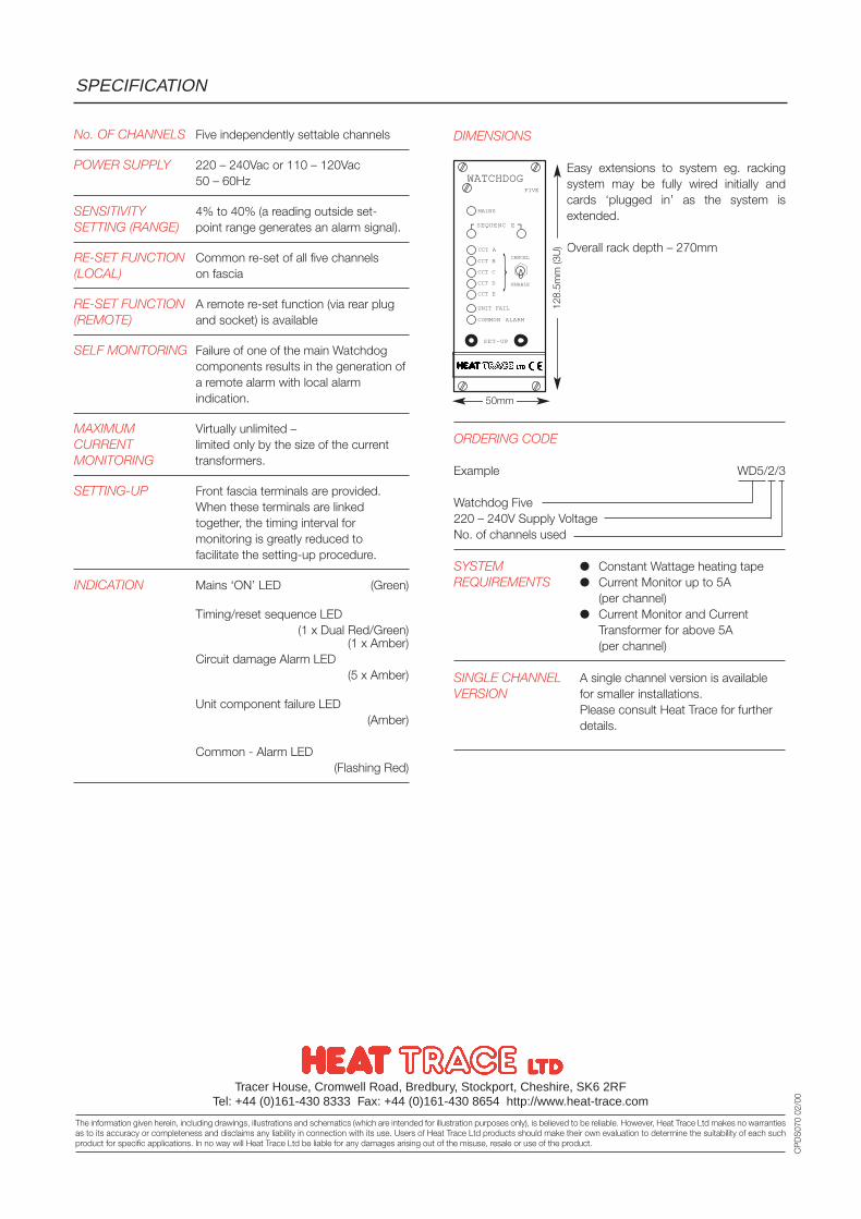
DIMENSIONS
Easy extensions to system eg. rackingsystem may be fully wired initially andcards ‘plugged in’ as the system isextended.
Overall rack depth – 270mm
ORDERING CODE
Example WD5/2/3
Watchdog Five220 – 240V Supply VoltageNo. of channels used
SYSTEM Constant Wattage heating tapeREQUIREMENTS Current Monitor up to 5A
(per channel) Current Monitor and Current
Transformer for above 5A(per channel)
SINGLE CHANNEL A single channel version is availableVERSION for smaller installations.
Please consult Heat Trace for furtherdetails.
No. OF CHANNELS Five independently settable channels
POWER SUPPLY 220 – 240Vac or 110 – 120Vac50 – 60Hz
SENSITIVITY 4% to 40% (a reading outside set-SETTING (RANGE) point range generates an alarm signal).
RE-SET FUNCTION Common re-set of all five channels(LOCAL) on fascia
RE-SET FUNCTION A remote re-set function (via rear plug(REMOTE) and socket) is available
SELF MONITORING Failure of one of the main Watchdogcomponents results in the generation ofa remote alarm with local alarmindication.
MAXIMUM Virtually unlimited –CURRENT limited only by the size of the currentMONITORING transformers.
SETTING-UP Front fascia terminals are provided.When these terminals are linkedtogether, the timing interval formonitoring is greatly reduced tofacilitate the setting-up procedure.
INDICATION Mains ‘ON’ LED (Green)
Timing/reset sequence LED(1 x Dual Red/Green)
(1 x Amber)Circuit damage Alarm LED
(5 x Amber)
Unit component failure LED(Amber)
Common - Alarm LED(Flashing Red)
SPECIFICATION
Tracer House, Cromwell Road, Bredbury, Stockport, Cheshire, SK6 2RFTel: +44 (0)161-430 8333 Fax: +44 (0)161-430 8654 http://www.heat-trace.com
The information given herein, including drawings, illustrations and schematics (which are intended for illustration purposes only), is believed to be reliable. However, Heat Trace Ltd makes no warrantiesas to its accuracy or completeness and disclaims any liability in connection with its use. Users of Heat Trace Ltd products should make their own evaluation to determine the suitability of each suchproduct for specific applications. In no way will Heat Trace Ltd be liable for any damages arising out of the misuse, resale or use of the product.
CP
DS
070
02/0
0
50mm
128.
5mm
(3U
)
WATCHDOG
MAINS
FIVE
SEQUENC E
CCT A
CCT B
CCT C
CCT D
CCT E
ENABLE
CANCELUNIT FAIL
COMMON ALARM
SET-UP
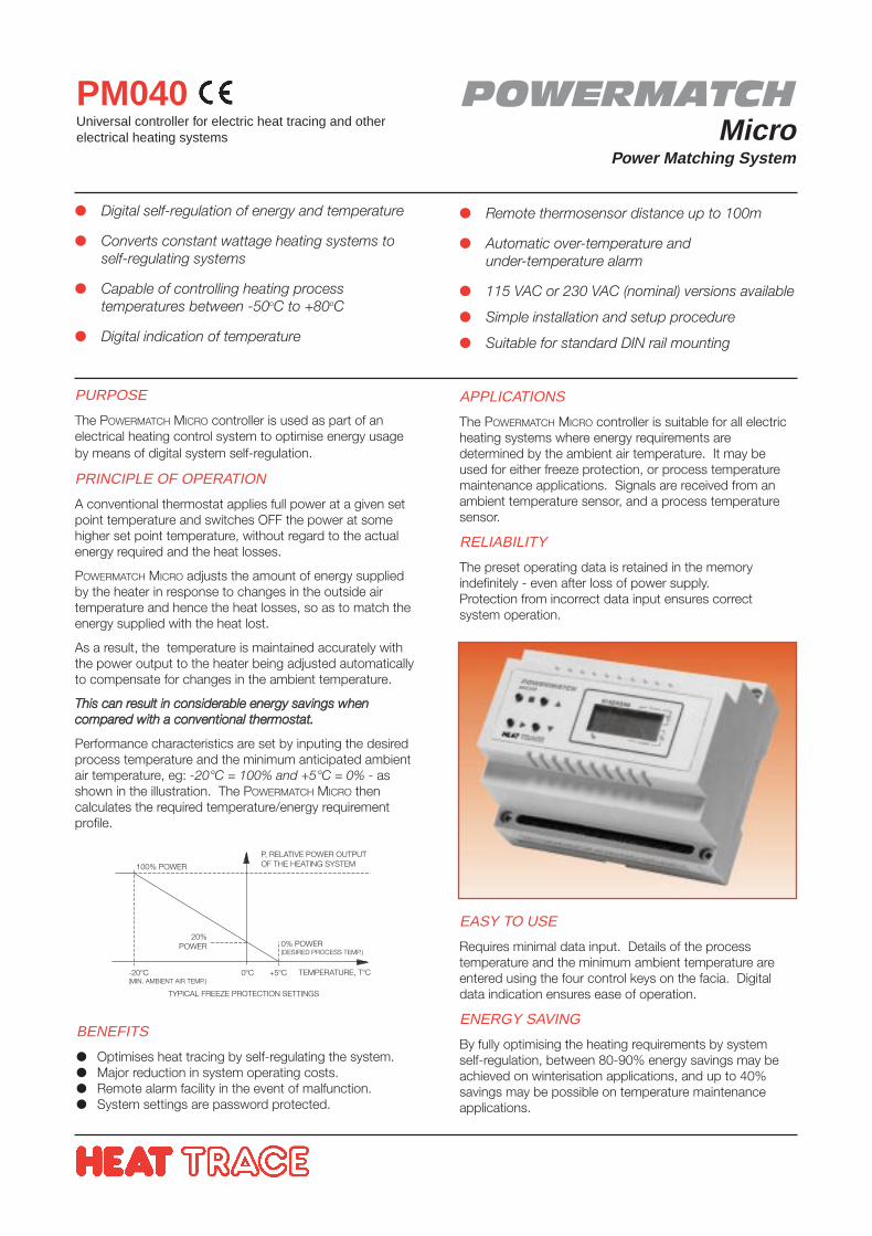
POWERMATCHMicro
Power Matching System
PM040Universal controller for electric heat tracing and otherelectrical heating systems
PURPOSE
The POWERMATCH MICRO controller is used as part of anelectrical heating control system to optimise energy usageby means of digital system self-regulation.
PRINCIPLE OF OPERATION
A conventional thermostat applies full power at a given setpoint temperature and switches OFF the power at somehigher set point temperature, without regard to the actualenergy required and the heat losses.
POWERMATCH MICRO adjusts the amount of energy suppliedby the heater in response to changes in the outside airtemperature and hence the heat losses, so as to match theenergy supplied with the heat lost.
As a result, the temperature is maintained accurately withthe power output to the heater being adjusted automaticallyto compensate for changes in the ambient temperature.
TThhiiss ccaann rreessuulltt iinn ccoonnssiiddeerraabbllee eenneerrggyy ssaavviinnggss wwhheennccoommppaarreedd wwiitthh aa ccoonnvveennttiioonnaall tthheerrmmoossttaatt..
Performance characteristics are set by inputing the desiredprocess temperature and the minimum anticipated ambientair temperature, eg: -20°C = 100% and +5°C = 0% - asshown in the illustration. The POWERMATCH MICRO thencalculates the required temperature/energy requirementprofile.
Digital self-regulation of energy and temperature
Converts constant wattage heating systems toself-regulating systems
Capable of controlling heating processtemperatures between -50oC to +80oC
Digital indication of temperature
Remote thermosensor distance up to 100m
Automatic over-temperature andunder-temperature alarm
115 VAC or 230 VAC (nominal) versions available
Simple installation and setup procedure
Suitable for standard DIN rail mounting
APPLICATIONS
The POWERMATCH MICRO controller is suitable for all electricheating systems where energy requirements aredetermined by the ambient air temperature. It may beused for either freeze protection, or process temperaturemaintenance applications. Signals are received from anambient temperature sensor, and a process temperaturesensor.
RELIABILITY
The preset operating data is retained in the memoryindefinitely - even after loss of power supply.Protection from incorrect data input ensures correctsystem operation.
BENEFITS
Optimises heat tracing by self-regulating the system. Major reduction in system operating costs. Remote alarm facility in the event of malfunction. System settings are password protected.
EASY TO USE
Requires minimal data input. Details of the processtemperature and the minimum ambient temperature areentered using the four control keys on the facia. Digitaldata indication ensures ease of operation.
ENERGY SAVING
By fully optimising the heating requirements by systemself-regulation, between 80-90% energy savings may beachieved on winterisation applications, and up to 40%savings may be possible on temperature maintenanceapplications.
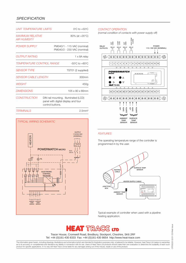
CONTACT OPERATION(normal condition of contacts with power supply off)
UNIT TEMPERATURE LIMITS 0oC to +50oC
MAXIMUM RELATIVE 80% (at +35°C)AIR HUMIDITY
POWER SUPPLY PM040/1 - 115 VAC (nominal)PM040/2 - 230 VAC (nominal)
OUTPUT RATING 1 x 8A relay
TEMPERATURE CONTROL RANGE -50oC to +80oC
SENSOR TYPE TST01 (2 supplied)
SENSOR CABLE LENGTH 300mm
WEIGHT 450g
DIMENSIONS 105 x 90 x 66mm
CONSTRUCTION DIN rail mounting. Illuminated (LCD)panel with digital display and fourcontrol buttons.
TERMINALS 2.5mm²
SPECIFICATION
Tracer House, Cromwell Road, Bredbury, Stockport, Cheshire, SK6 2RFTel: +44 (0)161-430 8333 Fax: +44 (0)161-430 8654 http://www.heat-trace.com
The information given herein, including drawings, illustrations and schematics (which are intended for illustration purposes only), is believed to be reliable. However, Heat Trace Ltd makes no warrantiesas to its accuracy or completeness and disclaims any liability in connection with its use. Users of Heat Trace Ltd products should make their own evaluation to determine the suitability of each suchproduct for specific applications. In no way will Heat Trace Ltd be liable for any damages arising out of the misuse, resale or use of the product.
CP
DS
220
02/0
1 C
D/W
ebIs
sue
FEATURES
The operating temperature range of the controller isprogrammed in by the user.
Typical example of controller when used with a pipelineheating application.
POWERMATCHMICRO
RELAYK1
RELAYK2
RELAYK3
RELAYK4
1 2 3 4 5 6 7 8 9 10 11 12 13 14 15 16
18 1732 31 30 29 28 27 26 25 24 23 22 21 20 19
K1 K2 K3 K4oC
%
POWER115 / 230 VAC (NOMINAL)
RELAYOUTPUTS
AMBIENTTEMP
SENSORD
ATA
+5V
EA
RT
H
SURFACE TEMP
SENSOR
DAT
A
+5V
EA
RT
H
tsurface
tB POWER
NO
TU
SE
D
NO
TU
SE
D
8 A
MP
LOA
D
HI/
LO T
EM
PA
LAR
M
HEATINGCABLE
SURFACE TEMPSENSOR
HEATER SUPPLY CABLE
AMBIENT TEMPSENSOR
JUNCTIONBOX
TYPICAL WIRING SCHEMATIC
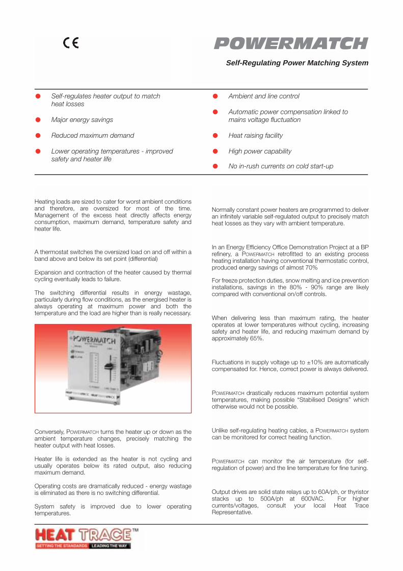
POWERMATCH(PATENTED)
Self-Regulating Power Matching System
PMProgrammable controller convertsconstant power into self-regulatingheat tracing systems.
PRINCIPLE OF OPERATION
Heating loads are sized to cater for worst ambient conditionsand therefore, are oversized for most of the time.Management of the excess heat directly affects energyconsumption, maximum demand, temperature safety andheater life.
Conventional ControlA thermostat switches the oversized load on and off within aband above and below its set point (differential)
Expansion and contraction of the heater caused by thermalcycling eventually leads to failure.
The switching differential results in energy wastage,particularly during flow conditions, as the energised heater isalways operating at maximum power and both thetemperature and the load are higher than is really necessary.
POWERMATCH ControlConversely, POWERMATCH turns the heater up or down as theambient temperature changes, precisely matching theheater output with heat losses.
Heater life is extended as the heater is not cycling andusually operates below its rated output, also reducingmaximum demand.
Operating costs are dramatically reduced - energy wastageis eliminated as there is no switching differential.
System safety is improved due to lower operatingtemperatures.
Self-regulates heater output to matchheat losses
Major energy savings
Reduced maximum demand
Lower operating temperatures - improvedsafety and heater life
Ambient and line control
Automatic power compensation linked tomains voltage fluctuation
Heat raising facility
High power capability
No in-rush currents on cold start-up
FEATURESSelf-Regulating, ProgrammableNormally constant power heaters are programmed to deliveran infinitely variable self-regulated output to precisely matchheat losses as they vary with ambient temperature.
Energy Savings up to 90%In an Energy Efficiency Office Demonstration Project at a BPrefinery, a POWERMATCH retrofitted to an existing processheating installation having conventional thermostatic control,produced energy savings of almost 70%
For freeze protection duties, snow melting and ice preventioninstallations, savings in the 80% - 90% range are likelycompared with conventional on/off controls.
Improved Safety, Life and Reduced Maximum DemandWhen delivering less than maximum rating, the heateroperates at lower temperatures without cycling, increasingsafety and heater life, and reducing maximum demand byapproximately 65%.
Mains Voltage CompensationFluctuations in supply voltage up to ±10% are automaticallycompensated for. Hence, correct power is always delivered.
Stabilised Designs PossiblePOWERMATCH drastically reduces maximum potential systemtemperatures, making possible “Stabilised Designs” whichotherwise would not be possible.
Can be Monitored for Correct OperationUnlike self-regulating heating cables, a POWERMATCH systemcan be monitored for correct heating function.
Dual ControlPOWERMATCH can monitor the air temperature (for self-regulation of power) and the line temperature for fine tuning.
High Power CapabilityOutput drives are solid state relays up to 60A/ph, or thyristorstacks up to 500A/ph at 600VAC. For highercurrents/voltages, consult your local Heat TraceRepresentative.
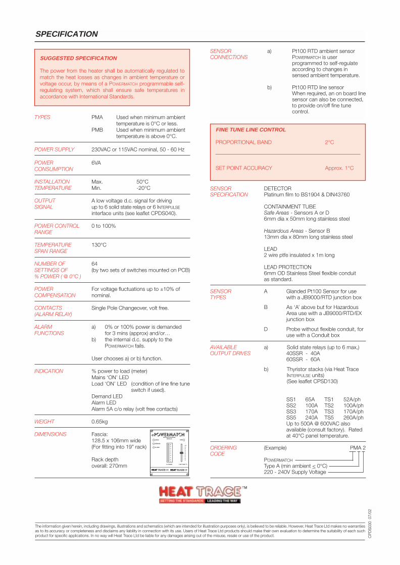
SPECIFICATION
CP
DS
030
07/
02
SENSOR DETECTORSPECIFICATION Platinum film to BS1904 & DIN43760
CONTAINMENT TUBESafe Areas - Sensors A or D6mm dia x 50mm long stainless steel
Hazardous Areas - Sensor B13mm dia x 80mm long stainless steel
LEAD2 wire ptfe insulated x 1m long
LEAD PROTECTION6mm OD Stainless Steel flexible conduitas standard.
SENSOR A Glanded Pt100 Sensor for useTYPES with a JB9000/RTD junction box
B As ‘A’ above but for HazardousArea use with a JB9000/RTD/EXjunction box
D Probe without flexible conduit, foruse with a Conduit box
AVAILABLE a) Solid state relays (up to 6 max,)OUTPUT DRIVES 40SSR - 40A
60SSR - 60A
b) Thyristor stacks (via Heat TraceINTERPULSE units)(See leaflet CPSD130)
Single Phase Three PhaseSS1 65A TS1 52A/phSS2 100A TS2 100A/phSS3 170A TS3 170A/phSS5 240A TS5 260A/phUp to 500A @ 600VAC also available (consult factory). Rated at 40°C panel temperature.
ORDERING (Example) PMA 2CODE
POWERMATCH
Type A (min ambient < 0°C)220 - 240V Supply Voltage
TYPES PMA Used when minimum ambienttemperature is 0°C or less.
PMB Used when minimum ambienttemperature is above 0°C.
POWER SUPPLY 230VAC or 115VAC nominal, 50 - 60 Hz
POWER 6VACONSUMPTION
INSTALLATION Max. 50°CTEMPERATURE Min. -20°C
OUTPUT A low voltage d.c. signal for drivingSIGNAL up to 6 solid state relays or 6 INTERPULSE
interface units (see leaflet CPDS040).
POWER CONTROL 0 to 100%RANGE
TEMPERATURE 130°CSPAN RANGE
NUMBER OF 64SETTINGS OF (by two sets of switches mounted on PCB)% POWER ( @ 0°C )
POWER For voltage fluctuations up to ±10% ofCOMPENSATION nominal.
CONTACTS Single Pole Changeover, volt free.(ALARM RELAY)
ALARM a) 0% or 100% power is demandedFUNCTIONS for 3 mins (approx) and/or…
b) the internal d.c. supply to thePOWERMATCH fails.
User chooses a) or b) function.
INDICATION % power to load (meter)Mains ‘ON’ LEDLoad ‘ON’ LED (condition of line fine tune
switch if used).Demand LEDAlarm LEDAlarm 5A c/o relay (volt free contacts)
WEIGHT 0.65kg
DIMENSIONS Fascia:128.5 x 106mm wide(For fitting into 19” rack)
Rack depthoverall: 270mm
SUGGESTED SPECIFICATION
The power from the heater shall be automatically regulated tomatch the heat losses as changes in ambient temperature orvoltage occur, by means of a POWERMATCH programmable self-regulating system, which shall ensure safe temperatures inaccordance with International Standards.
FINE TUNE LINE CONTROL
PROPORTIONAL BAND 2°C
SET POINT ACCURACY Approx. 1°C
SENSOR a) Pt100 RTD ambient sensorCONNECTIONS POWERMATCH is user
programmed to self-regulateaccording to changes insensed ambient temperature.
b) Pt100 RTD line sensorWhen required, an on board linesensor can also be connected,to provide on/off fine tune control.
MAINS LINE
DEMAND
ALARM
MASTER PROGRAMMODULE
% POWER LINE TEMP oC
100
90
80
70
60
50
40
30
20
10
100
90
80
70
60
50
40
30
20
10
Tracer House, Cromwell Road, Bredbury, Stockport, Cheshire, SK6 2RF, UKTel: +44(0)161-430 8333 Fax: +44(0)161-430 8654 http://www.heat-trace.com
The information given herein, including drawings, illustrations and schematics (which are intended for illustration purposes only), is believed to be reliable. However, Heat Trace Ltd makes no warrantiesas to its accuracy or completeness and disclaims any liability in connection with its use. Users of Heat Trace Ltd products should make their own evaluation to determine the suitability of each suchproduct for specific applications. In no way will Heat Trace Ltd be liable for any damages arising out of the misuse, resale or use of the product.
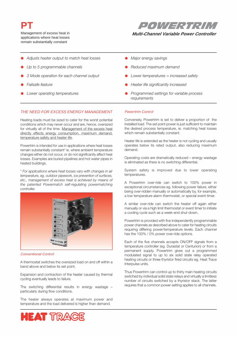
POWERTRIMMulti-Channel Variable Power Controller
PTManagement of excess heat inapplications where heat lossesremain substantially constant
THE NEED FOR EXCESS ENERGY MANAGEMENT
Heating loads must be sized to cater for the worst potentialconditions which may never occur and are, hence, oversizedfor virtually all of the time. Management of the excess heatdirectly effects energy consumption, maximum demand,temperature safety and heater life.
Powertrim is intended for use in applications where heat lossesremain substantially constant* ie. where ambient temperaturechanges either do not occur, or do not significantly affect heatlosses. Examples are buried pipelines and hot water pipes inheated buildings.
* For applications where heat losses vary with changes in airtemperature, eg. outdoor pipework, ice prevention of surfaces,etc., management of excess heat is achieved by means ofthe patented Powermatch self-regulating powermatchingcontroller.
Adjusts heater output to match heat losses
Up to 5 programmable channels
3 Mode operation for each channel output
Failsafe feature
Lower operating temperatures
Major energy savings
Reduced maximum demand
Lower temperatures = increased safety
Heater life significantly increased
Programmed settings for variable processrequirements
Powertrim Control
Conversely, Powertrim is set to deliver a proportion of theinstalled load. The set point power is just sufficient to maintainthe desired process temperature, ie. matching heat losseswhich remain substantially constant.
Heater life is extended as the heater is not cycling and usuallyoperates below its rated output, also reducing maximumdemand.
Operating costs are dramatically reduced – energy wastageis eliminated as there is no switching differential.
System safety is improved due to lower operatingtemperatures.
A Powertrim over-ride can switch to 100% power inexceptional circumstances eg. following power failure, eitherbeing over-ridden manually or automatically by, for example,a low temperature alarm thermostat, or special event timer.
A similar over-ride can switch the heater off again eithermanually or via a high limit thermostat or event timer to initiatea cooling cycle such as a week-end shut-down.
Powertrim is provided with five independently programmablepower channels as described above to cater for heating circuitsrequiring differing power/temperature levels. Each channelhas the 100% / 0% power over-ride options.
Each of the five channels accepts ON/OFF signals from atemperature controller (eg. Durastat or Centurion) or from apermanent supply. Powertrim gives out a programmedmodulated signal to up to six solid state relay operatedheating circuits or three thyristor fired circuits eg. Heat TraceInterpulse units.
Thus Powertrim can control up to thirty main heating circuitsswitched by individual solid state relays and virtually a limitlessnumber of circuits switched by a thyristor stack. The latterrequires that a common power setting applies to all channels.
Conventional Control
A thermostat switches the oversized load on and off within aband above and below its set point.
Expansion and contraction of the heater caused by thermalcycling eventually leads to failure.
The switching differential results in energy wastage –particularly during flow conditions.
The heater always operates at maximum power andtemperature and the load delivered is higher than demand.
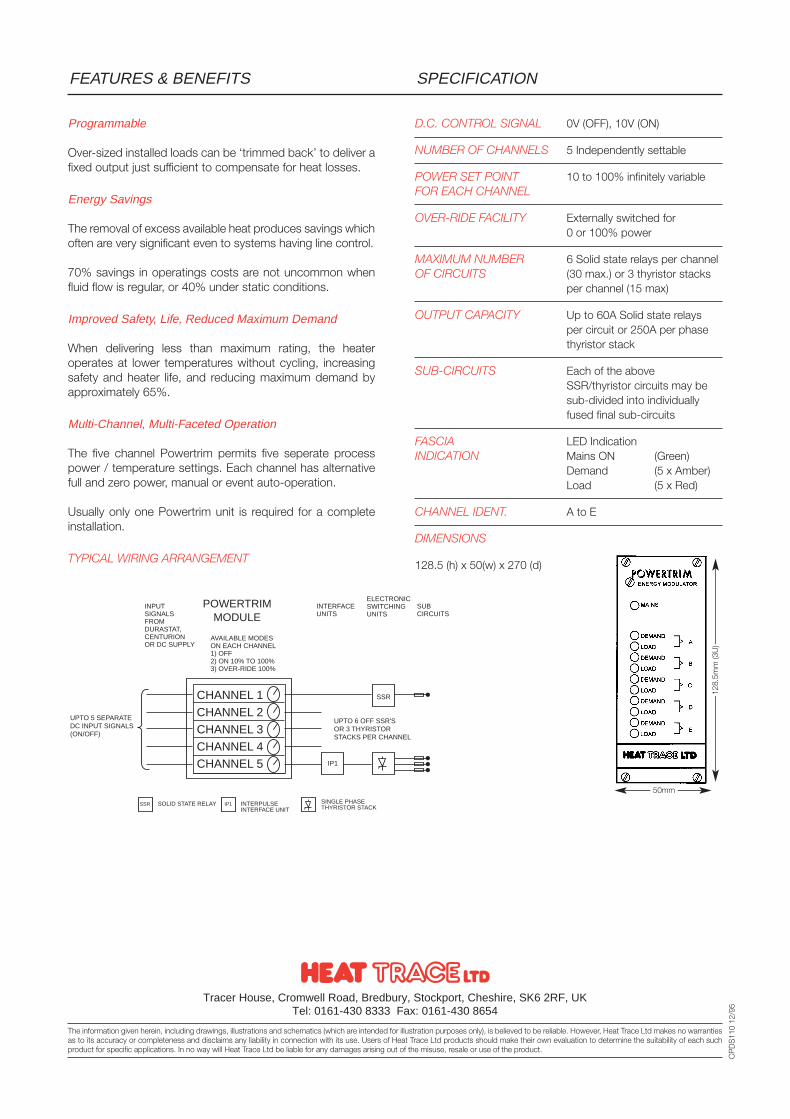
D.C. CONTROL SIGNAL 0V (OFF), 10V (ON)
NUMBER OF CHANNELS 5 Independently settable
POWER SET POINT 10 to 100% infinitely variableFOR EACH CHANNEL
OVER-RIDE FACILITY Externally switched for0 or 100% power
MAXIMUM NUMBER 6 Solid state relays per channelOF CIRCUITS (30 max.) or 3 thyristor stacks
per channel (15 max)
OUTPUT CAPACITY Up to 60A Solid state relaysper circuit or 250A per phasethyristor stack
SUB-CIRCUITS Each of the aboveSSR/thyristor circuits may besub-divided into individuallyfused final sub-circuits
FASCIA LED IndicationINDICATION Mains ON (Green)
Demand (5 x Amber)Load (5 x Red)
CHANNEL IDENT. A to E
DIMENSIONS
128.5 (h) x 50(w) x 270 (d)
SPECIFICATIONFEATURES & BENEFITS
Tracer House, Cromwell Road, Bredbury, Stockport, Cheshire, SK6 2RF, UKTel: 0161-430 8333 Fax: 0161-430 8654
The information given herein, including drawings, illustrations and schematics (which are intended for illustration purposes only), is believed to be reliable. However, Heat Trace Ltd makes no warrantiesas to its accuracy or completeness and disclaims any liability in connection with its use. Users of Heat Trace Ltd products should make their own evaluation to determine the suitability of each suchproduct for specific applications. In no way will Heat Trace Ltd be liable for any damages arising out of the misuse, resale or use of the product.
CP
DS
110
12/9
5
50mm
128.
5mm
(3U
)
Programmable
Over-sized installed loads can be ‘trimmed back’ to deliver afixed output just sufficient to compensate for heat losses.
Energy Savings
The removal of excess available heat produces savings whichoften are very significant even to systems having line control.
70% savings in operatings costs are not uncommon whenfluid flow is regular, or 40% under static conditions.
Improved Safety, Life, Reduced Maximum Demand
When delivering less than maximum rating, the heateroperates at lower temperatures without cycling, increasingsafety and heater life, and reducing maximum demand byapproximately 65%.
Multi-Channel, Multi-Faceted Operation
The five channel Powertrim permits five seperate processpower / temperature settings. Each channel has alternativefull and zero power, manual or event auto-operation.
Usually only one Powertrim unit is required for a completeinstallation.
TYPICAL WIRING ARRANGEMENT
CHANNEL 1CHANNEL 2CHANNEL 3CHANNEL 4CHANNEL 5
SSR SOLID STATE RELAY IP1 INTERPULSEINTERFACE UNIT
SINGLE PHASETHYRISTOR STACK
IP1
SSR
UPTO 6 OFF SSR'SOR 3 THYRISTORSTACKS PER CHANNEL
UPTO 5 SEPARATEDC INPUT SIGNALS(ON/OFF)
INPUTSIGNALSFROMDURASTAT,CENTURIONOR DC SUPPLY
AVAILABLE MODESON EACH CHANNEL1) OFF2) ON 10% TO 100%3) OVER-RIDE 100%
INTERFACEUNITS
SUBCIRCUITS
ELECTRONICSWITCHINGUNITS
POWERTRIMMODULE
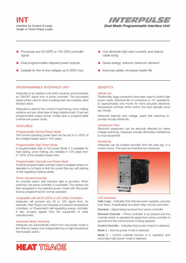
INTERPULSEDual Mode Programmable Interface Unit
INTInterface for Control of LargeSingle or Three Phase Loads
PROGRAMMABLE INTERFACE UNIT
Interpulse is an interface unit which receives and processesan ON/OFF signal from a prime controller. The processedsignal is then used to drive a heating load via a suitably ratedthyristor stack.
Interpulse is used for the control of heat tracing, snow meltingsystems and any other type of large resistive load. It has twoprogrammable output power modes plus a programmableoverride low power mode.
FEATURES
Programmable Normal Power ModeThe normal operating power level can be set to 0–100% ofthe installed heater load in 10% steps.
Programmable High Power ModeA programmable high or full power Mode 2 is available forheat raising, snow melting, etc; settable in 10% steps from0–100% of the installed heater load.
Programmable Override Low Power ModeA further programmable override mode is available where it isdesirable to cut back or limit the current flow eg. soft startingof self-regulating heating cables.
Power Demand OverrideAn override switch with indicator light is provided. Whenswitched, the prime controller is overridden. The heaters arethen energised in the selected power mode with the powerlevel as programmed for normal operation.
Compatible with all 0V (OFF) or 10V (ON) ControllersInterpulse will process any 0V or 10V signal from, forexample, Heat Trace’s own Durastat or Centurion temperaturecontrollers, or Powermatch self-regulating energy controller.It also accepts signals from the equipment of othermanufacturers.
Automatic Mode SwitchingInterpulse can automatically switch from one power mode tothe other by means of an independent low or high temperaturethermostatic switch.
Processes any 0V (OFF) or 10V (ON) controllersignal
Dual programmable stepped power outputs
Suitable for line-to-line voltages up to 600V max.
Can eliminate high start currents, and reducecable sizing
Saves energy, reduces maximum demand
Improves safety, increases heater life
BENEFITS
Infinite LifeTraditionally, large contactors have been used to switch highpower loads. Electrical life of contactors is 105 operations,or approximately one month for more accurate electronictemperature controls which switch the load typically twiceper minute.
Interpulse features zero voltage, spark free switching toprovide virtually infinite life.
Interference FreeElectronic equipment can be seriously affected by mainsvoltage switching. Interpulse virtually eliminates interferenceto local equipment.
MonitoringInterpulse can be located remotely from the load (eg. in acontrol room). The load can therefore be monitored.
LED IndicationSafe Loop – Indicates that internal power supplies, processover temp. (if applicable) and alarm relay circuitry are intact.
Demand – Signal being received from prime controller.
Demand Override – Prime controller is by-passed and theoverride switch is operated (ie signal from prime controller isignored and the normal power is being applied).
Control Override – Indicates that power mode 2 is selected.
Mode 1 – Normal power mode is selected.
Mode 2 – Control override function is in operation andsecondary high power mode is selected.
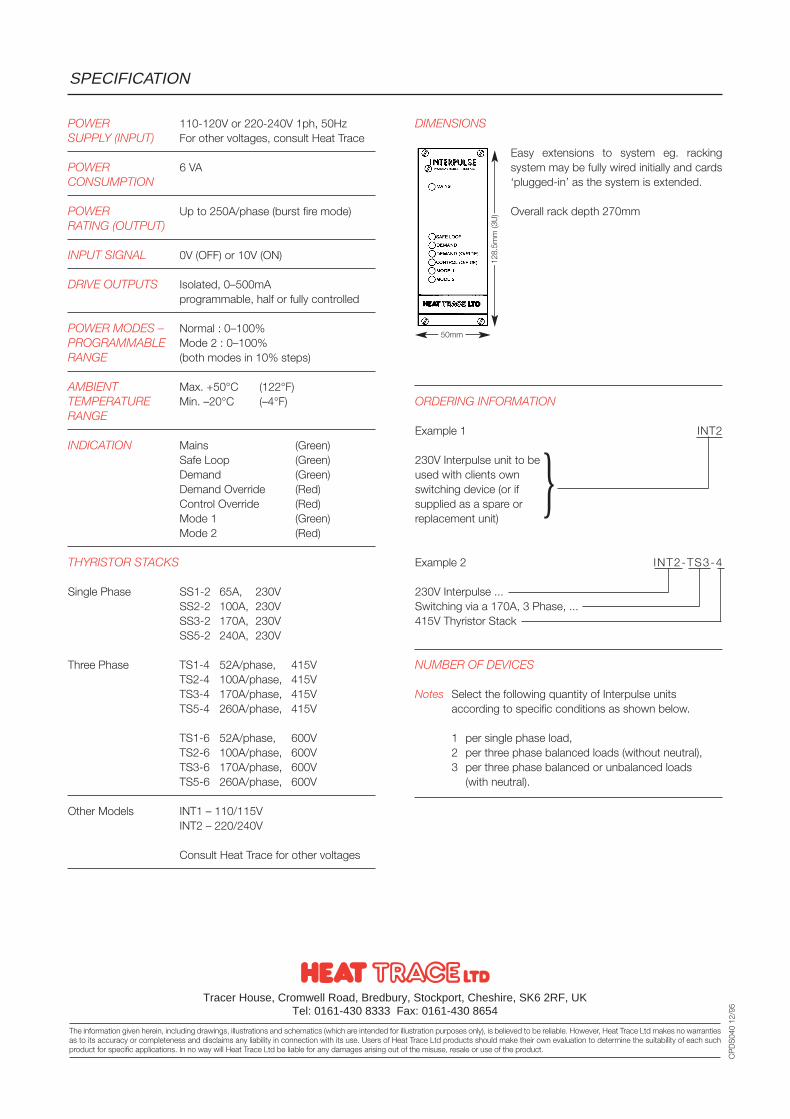
POWER 110-120V or 220-240V 1ph, 50HzSUPPLY (INPUT) For other voltages, consult Heat Trace
POWER 6 VACONSUMPTION
POWER Up to 250A/phase (burst fire mode)RATING (OUTPUT)
INPUT SIGNAL 0V (OFF) or 10V (ON)
DRIVE OUTPUTS Isolated, 0–500mAprogrammable, half or fully controlled
POWER MODES – Normal : 0–100%PROGRAMMABLE Mode 2 : 0–100%RANGE (both modes in 10% steps)
AMBIENT Max. +50°C (122°F)TEMPERATURE Min. –20°C (–4°F)RANGE
INDICATION Mains (Green)Safe Loop (Green)Demand (Green)Demand Override (Red)Control Override (Red)Mode 1 (Green)Mode 2 (Red)
THYRISTOR STACKS
Single Phase SS1-2 65A, 230VSS2-2 100A, 230VSS3-2 170A, 230VSS5-2 240A, 230V
Three Phase TS1-4 52A/phase, 415VTS2-4 100A/phase, 415VTS3-4 170A/phase, 415VTS5-4 260A/phase, 415V
TS1-6 52A/phase, 600VTS2-6 100A/phase, 600VTS3-6 170A/phase, 600VTS5-6 260A/phase, 600V
Other Models INT1 – 110/115VINT2 – 220/240V
Consult Heat Trace for other voltages
DIMENSIONS
Easy extensions to system eg. rackingsystem may be fully wired initially and cards‘plugged-in’ as the system is extended.
Overall rack depth 270mm
ORDERING INFORMATION
Example 1 INT2
230V Interpulse unit to beused with clients ownswitching device (or ifsupplied as a spare orreplacement unit)
Example 2 INT2-TS3-4
230V Interpulse ...Switching via a 170A, 3 Phase, ...415V Thyristor Stack
NUMBER OF DEVICES
Notes Select the following quantity of Interpulse units according to specific conditions as shown below.
1 per single phase load,2 per three phase balanced loads (without neutral),3 per three phase balanced or unbalanced loads
(with neutral).
SPECIFICATION
Tracer House, Cromwell Road, Bredbury, Stockport, Cheshire, SK6 2RF, UKTel: 0161-430 8333 Fax: 0161-430 8654
The information given herein, including drawings, illustrations and schematics (which are intended for illustration purposes only), is believed to be reliable. However, Heat Trace Ltd makes no warrantiesas to its accuracy or completeness and disclaims any liability in connection with its use. Users of Heat Trace Ltd products should make their own evaluation to determine the suitability of each suchproduct for specific applications. In no way will Heat Trace Ltd be liable for any damages arising out of the misuse, resale or use of the product.
CP
DS
040
12/9
5
50mm
128.
5mm
(3U
)

SNOFLOWCONTROLLER
Snow Melt & Ice Prevention Controller
SFCMonitors for snow/ice conditions,applying power for melting snow andice prevention of surfaces
SNOFLOW CONTROLLER AND SENSOR
The Snoflow Controller forms the heart of a comprehensiveSnoflow control system for the efficient control of heatingloads for snow melting and ice prevention of surfaces.
A Snoflow sensor mounted in the surface to be protectedmonitors for the surface temperature and presence ofmoisture or snow.
When pre-determined surface temperatures are reached, orif snow or moisture is detected, the Snoflow controllerprovides an appropriate signal to the Snoflow controlsystem for load application in the most efficient manner.
High efficiency control for snow melting/ice prevention system
Surface mounting ‘brick’ sensor
Remote control unit
Differentiates between snow and ice
Full system status indication
Modular 19” rack format
SNOFLOW CONTROL SYSTEM
An overall Snoflow Control system may comprise a range ofHeat Trace electronic devices.
Smaller installations may incorporate SnoMelt self-regulatingcables below the surface to be protected, whilst largersystems may use Snoflow constant power cables.
The control system for both types of cable are likely toincorporate:
Snoflow Controller/SensorDetermines load requirement by sensing presence of snow or moisture combined with a dangerously low surface temperature.
Durastat Proportional Temperature ControllerUsed as a seasonal switch activating the system as winter approaches.
Output DriveSolid State Relays for small loads or thyristors for large electrical loads.
A SnoMelt self-regulating cable system may additionally include:
Powertrim multi-channel power controllerFull power is applied when snow is sensed. A lower fixed power is applied for ice prevention.
A Snoflow constant power cable system may include self-regulating control (instead of the fixed output Powertrim),circuit health monitoring, and interface units when thyristordrives are required.
Powermatch Self-regulating ControllerAn energy efficient controller applies a variable heatingload (for ice prevention of surfaces) according to ambient temperature, and hence heat losses.
Interpulse Interface UnitFiring circuit used in conjunction with thyristor drives.Has programmable output modes.
Watchdog Circuit Health MonitorAlarm system monitors for circuit damage.
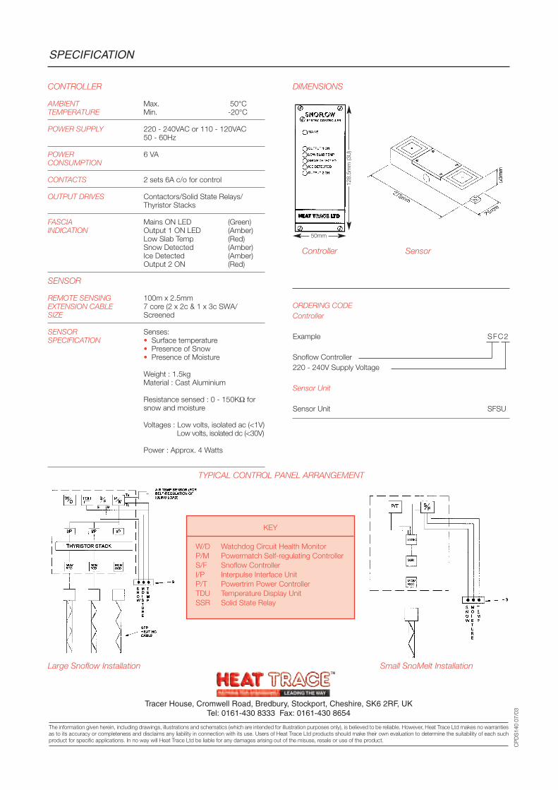
CONTROLLER
AMBIENT Max. 50°CTEMPERATURE Min. -20°C
POWER SUPPLY 220 - 240VAC or 110 - 120VAC50 - 60Hz
POWER 6 VACONSUMPTION
CONTACTS 2 sets 6A c/o for control
OUTPUT DRIVES Contactors/Solid State Relays/Thyristor Stacks
FASCIA Mains ON LED (Green)INDICATION Output 1 ON LED (Amber)
Low Slab Temp (Red)Snow Detected (Amber)Ice Detected (Amber)Output 2 ON (Red)
SENSOR
REMOTE SENSING 100m x 2.5mmEXTENSION CABLE 7 core (2 x 2c & 1 x 3c SWA/SIZE Screened
SENSOR Senses:SPECIFICATION • Surface temperature
• Presence of Snow• Presence of Moisture
Weight : 1.5kgMaterial : Cast Aluminium
Resistance sensed : 0 - 150KΩ for snow and moisture
Voltages : Low volts, isolated ac (<1V)Low volts, isolated dc (<30V)
Power : Approx. 4 Watts
ORDERING CODEController
Example SFC2
Snoflow Controller220 - 240V Supply Voltage
Sensor Unit
Sensor Unit SFSU
SPECIFICATION
Tracer House, Cromwell Road, Bredbury, Stockport, Cheshire, SK6 2RF, UKTel: 0161-430 8333 Fax: 0161-430 8654
The information given herein, including drawings, illustrations and schematics (which are intended for illustration purposes only), is believed to be reliable. However, Heat Trace Ltd makes no warrantiesas to its accuracy or completeness and disclaims any liability in connection with its use. Users of Heat Trace Ltd products should make their own evaluation to determine the suitability of each suchproduct for specific applications. In no way will Heat Trace Ltd be liable for any damages arising out of the misuse, resale or use of the product.
CP
DS
140
07/0
3
50mm
128.
5mm
(3U
)
DIMENSIONS
Controller Sensor
TYPICAL CONTROL PANEL ARRANGEMENT
Large Snoflow Installation Small SnoMelt Installation
KEY
W/D Watchdog Circuit Health MonitorP/M Powermatch Self-regulating ControllerS/F Snoflow ControllerI/P Interpulse Interface UnitP/T Powertrim Power ControllerTDU Temperature Display UnitSSR Solid State Relay
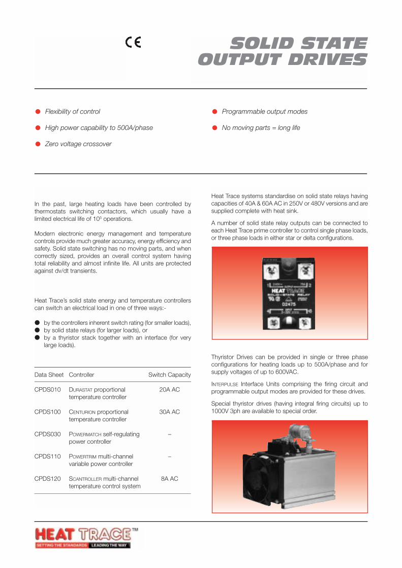
SOLID STATEOUTPUT DRIVES
SSR/SS/TSOutput drives for the control oflarge electrical loads
INTRODUCTION
In the past, large heating loads have been controlled bythermostats switching contactors, which usually have alimited electrical life of 105 operations.
Modern electronic energy management and temperaturecontrols provide much greater accuracy, energy efficiency andsafety. Solid state switching has no moving parts, and whencorrectly sized, provides an overall control system havingtotal reliability and almost infinite life. All units are protectedagainst dv/dt transients.
HEAT TRACE CONTROLLERS
Heat Trace’s solid state energy and temperature controllerscan switch an electrical load in one of three ways:-
by the controllers inherent switch rating (for smaller loads), by solid state relays (for larger loads), or by a thyristor stack together with an interface (for very
large loads).
Inherent Switch Rating of Heat Trace Controllers
Data Sheet Controller Switch Capacity
CPDS010 DURASTAT proportional 20A ACtemperature controller
CPDS100 CENTURION proportional 30A ACtemperature controller
CPDS030 POWERMATCH self-regulating –power controller
CPDS110 POWERTRIM multi-channel –variable power controller
CPDS120 SCANTROLLER multi-channel 8A ACtemperature control system
Flexibility of control
High power capability to 500A/phase
Zero voltage crossover
Programmable output modes
No moving parts = long life
Solid State RelaysHeat Trace systems standardise on solid state relays havingcapacities of 40A & 60A AC in 250V or 480V versions and aresupplied complete with heat sink.
A number of solid state relay outputs can be connected toeach Heat Trace prime controller to control single phase loads,or three phase loads in either star or delta configurations.
Thyristor DrivesThyristor Drives can be provided in single or three phaseconfigurations for heating loads up to 500A/phase and forsupply voltages of up to 600VAC.
INTERPULSE Interface Units comprising the firing circuit andprogrammable output modes are provided for these drives.
Special thyristor drives (having integral firing circuits) up to1000V 3ph are available to special order.
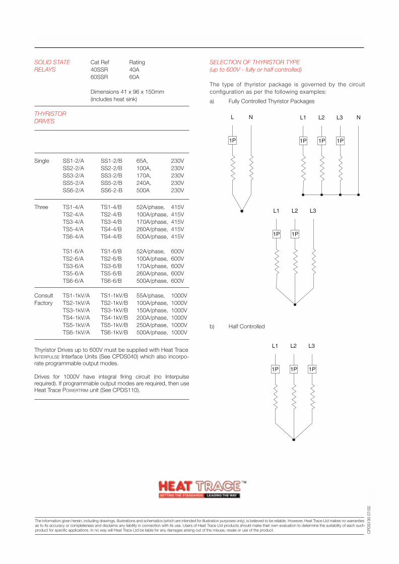
SELECTION OF THYRISTOR TYPE(up to 600V - fully or half controlled)
The type of thyristor package is governed by the circuitconfiguration as per the following examples:
a) Fully Controlled Thyristor Packages
b) Half Controlled
1P 1P
L1 L2 L3
SOLID STATE Cat Ref RatingRELAYS 40SSR 40A
60SSR 60A
Dimensions 41 x 96 x 150mm(includes heat sink)
THYRISTORDRIVES
Phase Fully Half NominalControlled Controlled Ampacity
Single SS1-2/A SS1-2/B 65A, 230VSS2-2/A SS2-2/B 100A, 230VSS3-2/A SS3-2/B 170A, 230VSS5-2/A SS5-2/B 240A, 230VSS6-2/A SS6-2-B 500A 230V
Three TS1-4/A TS1-4/B 52A/phase, 415VTS2-4/A TS2-4/B 100A/phase, 415VTS3-4/A TS3-4/B 170A/phase, 415VTS5-4/A TS4-4/B 260A/phase, 415VTS6-4/A TS4-4/B 500A/phase, 415V
TS1-6/A TS1-6/B 52A/phase, 600VTS2-6/A TS2-6/B 100A/phase, 600VTS3-6/A TS3-6/B 170A/phase, 600VTS5-6/A TS5-6/B 260A/phase, 600VTS6-6/A TS6-6/B 500A/phase, 600V
Consult TS1-1kV/A TS1-1kV/B 55A/phase, 1000VFactory TS2-1kV/A TS2-1kV/B 100A/phase, 1000V
TS3-1kV/A TS3-1kV/B 150A/phase, 1000VTS4-1kV/A TS4-1kV/B 200A/phase, 1000VTS5-1kV/A TS5-1kV/B 250A/phase, 1000VTS6-1kV/A TS6-1kV/B 500A/phase, 1000V
Thyristor Drives up to 600V must be supplied with Heat TraceINTERPULSE Interface Units (See CPDS040) which also incorpo-rate programmable output modes.
Drives for 1000V have integral firing circuit (no Interpulserequired). If programmable output modes are required, then useHeat Trace POWERTRIM unit (See CPDS110).
SPECIFICATION
CP
DS
130
07/0
2Tracer House, Cromwell Road, Bredbury, Stockport, Cheshire, SK6 2RF, UKTel: +44(0)161-430 8333 Fax: +44(0)161-430 8654 http://www.heat-trace.com
The information given herein, including drawings, illustrations and schematics (which are intended for illustration purposes only), is believed to be reliable. However, Heat Trace Ltd makes no warrantiesas to its accuracy or completeness and disclaims any liability in connection with its use. Users of Heat Trace Ltd products should make their own evaluation to determine the suitability of each suchproduct for specific applications. In no way will Heat Trace Ltd be liable for any damages arising out of the misuse, resale or use of the product.
1P
L N
1P 1P
L1 L2 L3 N
1P
1P 1P
L1 L2 L3
1P
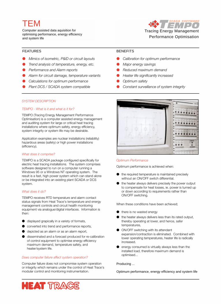
Tracing Energy Management
Performance Optimisation
TEMComputer assisted data aquisition foroptimising performance, energy efficiencyand system life
SYSTEM DESCRIPTION
TEMPO - What is it and what is it for?
TEMPO (Tracing Energy Management PerformanceOptimisation) is a computer assisted energy managementand auditing system for large or critical heat tracinginstallations where optimum safety, energy efficiency,system integrity or system life may be desirable.
Application examples are nuclear installations (reliability)hazardous areas (safety) or high power installations(efficiency).
What does it comprise?
TEMPO is a SCADA package configured specifically forelectric heat tracing installations. The system comprisessoftware designed to run on a computer running aWindows 95 or a Windows NT operating system. Theresult is a fast, high power system which can stand aloneor be integrated into an existing plant SCADA or DCSsystem.
What does it do?
TEMPO receives RTD temperature and alarm contactstatus signals from Heat Trace's temperature and energymanagement controls and circuit health monitoringequipment via analogue/digital interfaces. Information isthen:
displayed grapically in a variety of formats,
converted into trend and performance reports,
depicted as an alarm or as an alarm report,
disseminated and a forecast produced for re-calibrationof control equipment to optimise energy efficiencymaximum demand, temperature safety, andheater/system life.
Does computer failure affect system operation?
Computer failure does not compromise system operationor integrity which remains under the control of Heat Trace'smodular control and monitoring instrumentation.
FEATURES
Mimics of isometric, P&ID or circuit layouts
Trend analysis of temperature, energy, etc.
Performance and Alarm reports
Alarm for circuit damage, temperature variants
Calculations for optimum performance
Plant DCS / SCADA system compatible
BENEFITS
Calibration for optimum performance
Major energy savings
Reduced maximum demand
Heater life significantly increased
Optimum safety
Constant surveillance of system integrity
Optimum Performance
Optimum performance is achieved when:
the required temperature is maintained preciselywithout an ON/OFF switch differential.
the heater always delivers precisely the power outputto compensate for heat losses, ie. power is turned upor down according to requirements rather thanON/OFF switching.
When these conditions have been achieved;
there is no wasted energy
the heater always delivers less than its rated output,thereby operating at lower, and hence, safertemperatures,
ON/OFF switching with its attendantexpansion/contraction is eliminated. Combined withlower operating temperatures, heater life is radicallyincreased.
energy consumed is virtually always less than theinstalled load, therefore maximum demand isoptimised...
Producing ...
Optimum performance, energy efficiency and system life
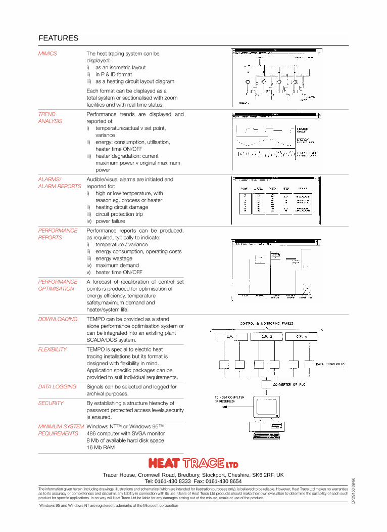
MIMICS The heat tracing system can be displayed:-i) as an isometric layoutii) in P & ID formatiii) as a heating circuit layout diagram
Each format can be displayed as a total system or sectionalised with zoom facilities and with real time status.
TREND Performance trends are displayed andANALYSIS reported of:
i) temperature:actual v set point, variance
ii) energy: consumption, utilisation, heater time ON/OFF
iii) heater degradation: current maximum power v original maximum power
ALARMS/ Audible/visual alarms are initiated and ALARM REPORTS reported for:
i) high or low temperature, with reason eg. process or heater
ii) heating circuit damageiii) circuit protection tripiv) power failure
PERFORMANCE Performance reports can be produced,REPORTS as required, typically to indicate:
i) temperature / varianceii) energy consumption, operating costsiii) energy wastageiv) maximum demandv) heater time ON/OFF
PERFORMANCE A forecast of recalibration of control setOPTIMISATION points is produced for optimisation of
energy efficiency, temperature safety,maximum demand and heater/system life.
DOWNLOADING TEMPO can be provided as a stand alone performance optimisation system orcan be integrated into an existing plant SCADA/DCS system.
FLEXIBILITY TEMPO is special to electric heat tracing installations but its format is designed with flexibility in mind. Application specific packages can be provided to suit individual requirements.
DATA LOGGING Signals can be selected and logged for archival purposes.
SECURITY By establishing a structure hierachy of password protected access levels,securityis ensured.
MINIMUM SYSTEM Windows NT™ or Windows 95™REQUIREMENTS 486 computer with SVGA monitor
8 Mb of available hard disk space16 Mb RAM
FEATURES
Tracer House, Cromwell Road, Bredbury, Stockport, Cheshire, SK6 2RF, UKTel: 0161-430 8333 Fax: 0161-430 8654
The information given herein, including drawings, illustrations and schematics (which are intended for illustration purposes only), is believed to be reliable. However, Heat Trace Ltd makes no warrantiesas to its accuracy or completeness and disclaims any liability in connection with its use. Users of Heat Trace Ltd products should make their own evaluation to determine the suitability of each suchproduct for specific applications. In no way will Heat Trace Ltd be liable for any damages arising out of the misuse, resale or use of the product.
CP
DS
150
09/9
6
Windows 95 and Windows NT are registered trademarks of the Microsoft corporation
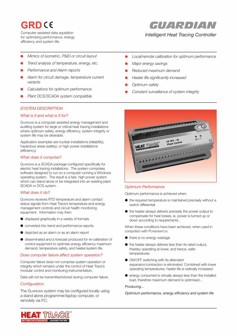
GUARDIANIntelligent Heat Tracing Controller
GRDComputer assisted data aquisitionfor optimising performance, energyefficiency and system life.
SYSTEM DESCRIPTION
What is it and what is it for?
GUARDIAN is a computer assisted energy management andauditing system for large or critical heat tracing installationswhere optimum safety, energy efficiency, system integrity orsystem life may be desirable.
Application examples are nuclear installations (reliability),hazardous areas (safety), or high power installations(efficiency).
What does it comprise?
GUARDIAN is a SCADA package configured specifically forelectric heat tracing installations. The system comprisessoftware designed to run on a computer running a Windowsoperating system. The result is a fast, high power systemwhich can stand alone or be integrated into an existing plantSCADA or DCS system.
What does it do?
GUARDIAN receives RTD temperature and alarm contactstatus signals from Heat Trace’s temperature and energymanagement controls and circuit health monitoringequipment. Information may then:
displayed graphically in a variety of formats
converted into trend and performance reports
depicted as an alarm or as an alarm report
disseminated and a forecast produced for re-calibration ofcontrol equipment to optimise energy efficiency maximumdemand, temperature safety, and heater/system life.
Does computer failure affect system operation?
Computer failure does not comprise system operation orintegrity which remains under the control of Heat Trace’smodular control and monitoring instrumentation.
Data will not be transmitted/stored during computer failure.
Configuration
The GUARDIAN system may be configured locally usinga stand alone programmer/laptop computer, orremotely via P.C.
Mimics of isometric, P&ID or circuit layout
Trend analysis of temperature, energy, etc.
Performance and Alarm reports
Alarm for circuit damage, temperature currentvariants
Calculations for optimum performance
Plant DCS/SCADA system compatible
Local/remote calibration for optimum performance
Major energy savings
Reduced maximum demand
Heater life significantly increased
Optimum safety
Constant surveillance of system integrity
Optimum Performance
Optimum performance is achieved when:
the required temperature is maintained precisely without aswitch differential
the heater always delivers precisely the power output tocompensate for heat losses, ie. power is turned up ordown according to requirements .
When these conditions have been achieved, when used inconjuntion with POWERMATCH;
there is no energy wastage
the heater always delivers less than its rated output,thereby operating at lower, and hence, safertemperatures
ON/OFF switching with its attendantexpansion/contraction is eliminated. Combined with loweroperating temperatures, heater life is radically increased.
energy consumed is virtually always less than the installedload, therefore maximum demand is optimised...
Producing...
Optimium performance, energy efficiency and system life
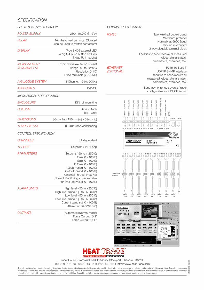
ELECTRICAL SPECIFICATION
POWER SUPPLY 230/110VAC @ 15VA
RELAY Non heat load carrying. 2A rated(can be used to switch contactors)
DISPLAY Type SKD9 external LED4 digit, 4 push button and key
6 way RJ11 socket
MEASUREMENT Pt100 3 wire excitation current(8 CHANNELS) Range -50 to +250oC
Resolution 0.1oCFixed terminals (+:-: GND)
ANALOGUE SYSTEM 8 Channel, 12 bit, 50kHz
APPROVALS LVD/CE
MECHANICAL SPECIFICATION
ENCLOSURE DIN rail mounting
COLOUR Base - BlackTop - Grey
DIMENSIONS 86mm (h) x 156mm (w) x 59mm (d)
TEMPERATURE 0 - 40oC non-condensing
CONTROL SPECIFICATION
CHANNELS 8 Independant
THEORY Setpoint + PID Loop
PARAMETERS Setpoint (-50 to + 250oC)P Gain (0 - 100%)I Gain (0 - 100%)
D Gain (0 - 100%)Loop Period (0 - 100%)
Output Period (0 - 100%)Channel “In Use” (Yes/No)
Current Monitoring - user settablefor time and value (0 - 100%)
ALARM LIMITS High level (-50 to +250oC)High level timeout (0 to 250 mins)
Low level (-50 to +250oC)Low level timeout (0 to 250 mins)
Current value set (0 - 100%)Alarm “In Use” (Yes/No)
OUTPUTS Automatic (Normal mode)Force Output “ON”
Force Output “OFF”
SPECIFICATION
CP
DS
270
07/0
2
COMMS SPECIFICATION
RS485 Two wire half dupley using“Modbus” protocol
Normally at 9600 BaudGround referenced
3 way plugable terminal block
Facilities to send/receive all measuredvalues, digital states,
parameters, overrides, etc.
ETHERNET RJ45 10 Base T(OPTIONAL) UDP IP SNMP Interface
facilities to send/receive allmeasured values, digital states,
parameters, overrides, etc.
Send asynchronous events (traps)configurable via a DHCP server
Tracer House, Cromwell Road, Bredbury, Stockport, Cheshire SK6 2RFTel: +44(0)161-430 8333 Fax: +44(0)161-430 8654 http://www.heat-trace.com
The information given herein, including drawings, illustrations and schematics (which are intended for illustration purposes only), is believed to be reliable. However, Heat Trace Ltd makes nowarranties as to its accuracy or completeness and disclaims any liability in connection with its use. Users of Heat Trace Ltd products should make their own evaluation to determine the suitabilityof each such product for specific applications. In no way will Heat Trace Ltd be liable for any damages arising out of the misuse, resale or use of the product.
Control panel terminals
Pt100 CH1
Pt100 CH1
Pt100 CH1
Pt100 CH1
Pt100 CH1
Pt100 CH1
Pt100 CH1
Pt100 CH1
1 2 3 4 5 6 7 8 9 10 11 12 13 14 15 16 17 18 19 20 21 22 23 24 25 26
27 28 29 30 31 32 33 34 35 36 37 38 39 40 41 42 43 44 45 46 47
COM A COM B
CH
1R
ly/S
SR
op(b
uild
)
CH
2R
ly/S
SR
op(b
uild
)
CH
3R
ly/S
SR
op(b
uild
)
CH
4R
ly/S
SR
op(b
uild
)
CH
5R
ly/S
SR
op(b
uild
)
CH
6R
ly/S
SR
op(b
uild
)
CH
7R
ly/S
SR
op(b
uild
)
CH
8R
ly/S
SR
op(b
uild
)
CH
faul
tRly
/SS
Rop
(bui
ld)
Fau
ltip
(loop
)24
V5
mA
EA
RT
H
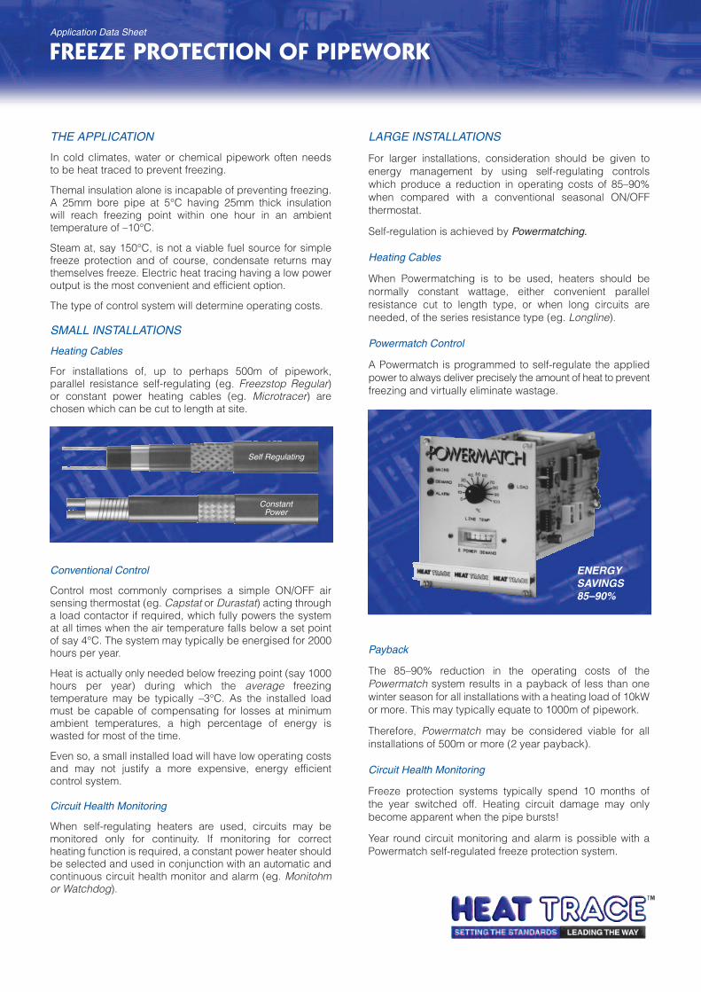
THE APPLICATION
In cold climates, water or chemical pipework often needsto be heat traced to prevent freezing.
Themal insulation alone is incapable of preventing freezing.A 25mm bore pipe at 5°C having 25mm thick insulationwill reach freezing point within one hour in an ambienttemperature of –10°C.
Steam at, say 150°C, is not a viable fuel source for simplefreeze protection and of course, condensate returns maythemselves freeze. Electric heat tracing having a low poweroutput is the most convenient and efficient option.
The type of control system will determine operating costs.
SMALL INSTALLATIONS
Heating Cables
For installations of, up to perhaps 500m of pipework,parallel resistance self-regulating (eg. Freezstop Regular)or constant power heating cables (eg. Microtracer) arechosen which can be cut to length at site.
LARGE INSTALLATIONS
For larger installations, consideration should be given toenergy management by using self-regulating controlswhich produce a reduction in operating costs of 85–90%when compared with a conventional seasonal ON/OFFthermostat.
Self-regulation is achieved by Powermatching.
Heating Cables
When Powermatching is to be used, heaters should benormally constant wattage, either convenient parallelresistance cut to length type, or when long circuits areneeded, of the series resistance type (eg. Longline).
Powermatch Control
A Powermatch is programmed to self-regulate the appliedpower to always deliver precisely the amount of heat to preventfreezing and virtually eliminate wastage.
Payback
The 85–90% reduction in the operating costs of thePowermatch system results in a payback of less than onewinter season for all installations with a heating load of 10kWor more. This may typically equate to 1000m of pipework.
Therefore, Powermatch may be considered viable for allinstallations of 500m or more (2 year payback).
Circuit Health Monitoring
Freeze protection systems typically spend 10 months ofthe year switched off. Heating circuit damage may onlybecome apparent when the pipe bursts!
Year round circuit monitoring and alarm is possible with aPowermatch self-regulated freeze protection system.
FREEZE PROTECTION OF PIPEWORK
Conventional Control
Control most commonly comprises a simple ON/OFF airsensing thermostat (eg. Capstat or Durastat) acting througha load contactor if required, which fully powers the systemat all times when the air temperature falls below a set pointof say 4°C. The system may typically be energised for 2000hours per year.
Heat is actually only needed below freezing point (say 1000hours per year) during which the average freezingtemperature may be typically –3°C. As the installed loadmust be capable of compensating for losses at minimumambient temperatures, a high percentage of energy iswasted for most of the time.
Even so, a small installed load will have low operating costsand may not justify a more expensive, energy efficientcontrol system.
Circuit Health Monitoring
When self-regulating heaters are used, circuits may bemonitored only for continuity. If monitoring for correctheating function is required, a constant power heater shouldbe selected and used in conjunction with an automatic andcontinuous circuit health monitor and alarm (eg. Monitohmor Watchdog).
ENERGYSAVINGS85–90%
Self Regulating
ConstantPower
Application Data Sheet
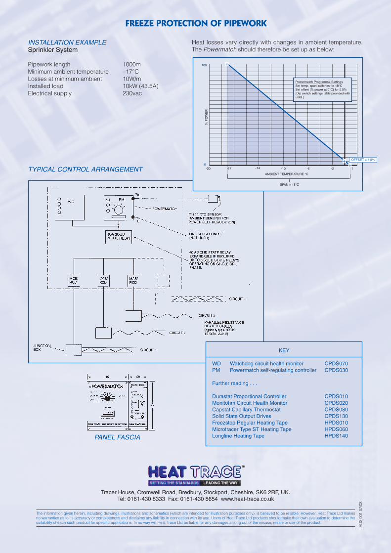
INSTALLATION EXAMPLESprinkler System
Pipework length 1000mMinimum ambient temperature –17°CLosses at minimum ambient 10W/mInstalled load 10kW (43.5A)Electrical supply 230vac
Heat losses vary directly with changes in ambient temperature.The Powermatch should therefore be set up as below:
KEY
WD Watchdog circuit health monitor CPDS070PM Powermatch self-regulating controller CPDS030
Further reading . . .
Durastat Proportional Controller CPDS010Monitohm Circuit Health Monitor CPDS020Capstat Capillary Thermostat CPDS080Solid State Output Drives CPDS130Freezstop Regular Heating Tape HPDS010Microtracer Type ST Heating Tape HPDS060Longline Heating Tape HPDS140
TYPICAL CONTROL ARRANGEMENT
PANEL FASCIA
FREEZE PROTECTION OF PIPEWORK
Tracer House, Cromwell Road, Bredbury, Stockport, Cheshire, SK6 2RF, UK.Tel: 0161-430 8333 Fax: 0161-430 8654 www.heat-trace.co.uk
The information given herein, including drawings, illustrations and schematics (which are intended for illustration purposes only), is believed to be reliable. However, Heat Trace Ltd makesno warranties as to its accuracy or completeness and disclaims any liability in connection with its use. Users of Heat Trace Ltd products should make their own evaluation to determine thesuitability of each such product for specific applications. In no way will Heat Trace Ltd be liable for any damages arising out of the misuse, resale or use of the product.
AD
S 00
1 07
/03
% P
OW
ER
OFFSET = 5·5%
SPAN = 18°C
AMBIENT TEMPERATURE °C
-20 -17 -14 -10 -6 -2 1
+
100
0
+
Powermatch Programme SettingsSet temp. span switches for 18°CSet offset (% power at 0°C) for 5.5%(Dip switch settings table provided withunits.)
+
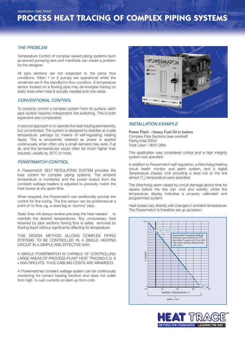
THE PROBLEM
Temperature Control of complex valved piping systems suchas around pumping sets and manifolds can create a problemfor the designer.
All pipe sections are not subjected to the same flowconditions. Often 1 or 2 pumps are operational whilst theremainder are in the standby/no flow condition. A temperaturesensor located on a flowing pipe may de-energise tracing onstatic lines when heat is actually needed and vice versa.
CONVENTIONAL CONTROL
To correctly control a complex system from its surface, eachpipe section requires independent line switching. This is bothexpensive and complicated.
A second approach is to operate the heat tracing permanently,but uncontrolled. The system is designed to stabilise at a safetemperature, perhaps by means of self-regulating heatingtapes. This is excessively wasteful as power is appliedcontinuously when often only a small demand may exist, if atall, and line temperatures would often be much higher thanrequired, usually by 30°C or more.
POWERMATCH CONTROL
A Powermatch SELF-REGULATING SYSTEM provides thebest control for complex piping systems. The ambienttemperature is monitored and the power output from theconstant wattage heaters is adjusted to precisely match theheat losses at any given time.
When required, the Powermatch can additionally provide linecontrol for fine tuning. The line sensor can be positioned at apoint of no flow, eg. a dead leg or ‘dummy’ pipe.
Static lines will always receive precisely the heat needed tomaintain the desired temperatures. Any unnecessary heatreceived by pipe sections having flow is safely removed byflowing liquid without significantly affecting its temperature.
THIS DESIGN METHOD ALLOWS COMPLEX PIPINGSYSTEMS TO BE CONTROLLED IN A SINGLE HEATINGCIRCUIT IN A SIMPLE AND EFFECTIVE WAY.
A SINGLE POWERMATCH IS CAPABLE OF CONTROLLINGLARGE AREAS OF PROCESS PLANT HEAT TRACING E.G. 6x 60A CIRCUITS. THUS CABLING COSTS ARE MINIMISED.
A Powermatched constant wattage system can be continuouslymonitoring for correct heating function and does not sufferfrom high in-rush currents on start-up from cold.
INSTALLATION EXAMPLE
Power Plant – Heavy Fuel Oil to boilersComplex Pipe Sections (see overleaf)Piping total 200mTotal Load = 9kW (39A)
This application was considered critical and a high integritysystem was specified.
In addition to Powermatch self-regulation, a Watchdog heatingcircuit health monitor and alarm system, and a digitalTemperature Display Unit providing a read out of the linesensor (TL) temperature were specified.
The Watchdog alarm raised by circuit damage allows time forrepairs before the line can cool and solidify, whilst thetemperature display indicates a properly calibrated andprogrammed system.
Heat losses vary directly with changes in ambient temperature.The Powermatch is therefore set up as below:
PROCESS HEAT TRACING OF COMPLEX PIPING SYSTEMS
% P
OW
ER
0%
85·7% @ 0°C
100
0
SPAN = 70°C
AMBIENT TEMPERATURE °C
-10 10 30 50 70
+
+
+
Powermatch Programme SettingsSet temp. span switches for 70°CSet offset (% power at 0°C) for 86%(Dip switch settings table providedwith units.)
Application Data Sheet
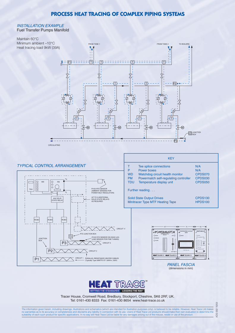
PROCESS HEAT TRACING OF COMPLEX PIPING SYSTEMS
Tracer House, Cromwell Road, Bredbury, Stockport, Cheshire, SK6 2RF, UK.Tel: 0161-430 8333 Fax: 0161-430 8654 www.heat-trace.co.uk
The information given herein, including drawings, illustrations and schematics (which are intended for illustration purposes only), is believed to be reliable. However, Heat Trace Ltd makesno warranties as to its accuracy or completeness and disclaims any liability in connection with its use. Users of Heat Trace Ltd products should make their own evaluation to determine thesuitability of each such product for specific applications. In no way will Heat Trace Ltd be liable for any damages arising out of the misuse, resale or use of the product.
AD
S 00
2 10
/03
WD
TDU
PM
Ta
TL
40A SOLIDSTATE RELAY
Pt100 RTD SENSOR(AMBIENT SENSING FORPOWER SELF-REGULATION)
UP TO 5 ADDITIONALSOLID STATE RELAYSAS REQUIRED
RTD JUNCTION BOX
CIRCUIT 3
CIRCUIT 2
CIRCUIT 'n'
CIRCUIT 1
Pt100 RTD SENSOR ON DEAD LEG(LINE SENSOR FOR FINE TUNING)
PARALLEL RESISTANCE HEATER CABLES(Typically Type 50MTF2-CF, 50W/m, 230V)
RCBO
JUNCTIONBOX
P1
P2
P3
RCBO RCBO
T T T
T P2
P3
P1
T
T
TT T T
JUNCTIONBOX
CIRCULATING
FROM TANK 1 FROM TANK 2 TO BOILERS
MMMM
KEY
T Tee splice connections N/AP Power boxes N/AWD Watchdog circuit health monitor CPDS070PM Powermatch self-regulating controller CPDS030TDU Temperature display unit CPDS050
Further reading . . .
Solid State Output Drives CPDS130Minitracer Type MTF Heating Tape HPDS100
INSTALLATION EXAMPLEFuel Transfer Pumps Manifold
Maintain 60°CMinimum ambient –10°CHeat tracing load 9kW (39A)
TYPICAL CONTROL ARRANGEMENT
PANEL FASCIA(dimensions in mm)
MAINS LINE
DEMAND
ALARM
MASTER PROGRAM MODULE
% POWER LINE TEMP oC
100
90
80
70
60
50
40
30
20
10
100
90
80
70
60
50
40
30
20
10
WATCHDOGFIVE
SEQUENCE
CANCEL
ENABLE
SET UP
CCT A
CCT B
CCT C
CCT D
CCT E
UNIT FAIL
COMMON ALARM
MAINS
TEMPERATURE DISPLAYUNIT
TYPE TDU 100
107 70 50
12
7
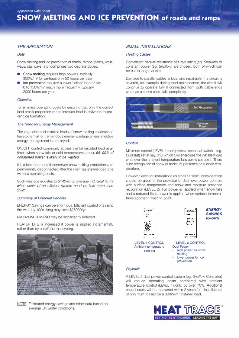
THE APPLICATION
Duty
Snow melting and ice prevention of roads, ramps, paths, walk-ways, stairways, etc. comprises two discrete duties:
Snow melting requires high powers, typically300W/m2 for perhaps only 50 hours per year;
Ice prevention requires a lower “idling” load of say0 to 150W/m2 much more frequently, typically2000 hours per year.
Objective
To minimise operating costs by ensuring that only the correct(and small) proportion of the installed load is delivered to pre-vent ice formation.
The Need for Energy Management
The large electrical installed loads of snow melting applicationshave potential for tremendous energy wastage unless effectiveenergy management is employed.
ON/OFF control commonly applies the full installed load at alltimes when snow falls or cold temperatures occur. 65–90% ofconsumed power is likely to be wasted.
It is a fact that many ill-conceived snowmelting installations arepermanently disconnected after the user has experienced onewinter’s operating costs.
Such wastage equates to $140/m2 at average industrial tarrifswhen costs of an efficient system need be little more than$5/m2.
Summary of Potential Benefits
ENERGY Savings can be enormous. Efficient control of a ramp6m wide by 100m long may save $25000/yr.
MAXIMUM DEMAND may be significantly reduced.
HEATER LIFE is increased if power is applied incrementallyrather than by on/off thermal cycling.
NOTE Estimated energy savings and other data based onaverage UK winter conditions.
SMALL INSTALLATIONS
Heating Cables
Convenient parallel resistance self-regulating (eg. SnoMelt) orconstant power (eg. Snoflow) are chosen, both of which canbe cut to length at site.
Damage to parallel cables is local and repairable. If a circuit issevered, for example during road maintenance, the circuit willcontinue to operate fully if connected from both cable endswhereas a series cable fails completely.
Control
Minimum control (LEVEL 1) comprises a seasonal switch (eg.Durastat) set at say, 3°C which fully energises the installed loadwhenever the ambient temperature falls below set point. Thereis no recognition of snow or moisture presence or surface tem-perature.
However, even for installations as small as 10m2, considerationshould be given to the provision of dual level power controlswith surface temperature and snow and moisture presencerecognition (LEVEL 2). Full power is applied when snow fallsand a reduced fixed power is applied when surface tempera-tures approach freezing point.
Payback
A LEVEL 2 dual power control system (eg. Snoflow Controller)will reduce operating costs compared with ambienttemperature control (LEVEL 1) only, by over 70%. Additionalcapital costs will be recovered within 2 years for installationsof only 15m2 based on a 300W/m2 installed load.
SNOW MELTING AND ICE PREVENTION of roads and rampsApplication Data Sheet
Self Regulating
ConstantPower
LEVEL 1 CONTROLAmbient temperature
sensing
LEVEL 2 CONTROLDual Power- high power for snow
melting- lower power for ice
prevention
ENERGYSAVINGS65–90%
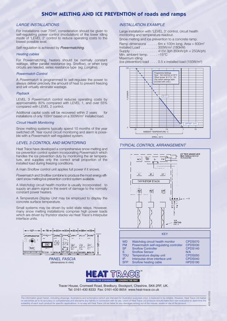
SNOW MELTING AND ICE PREVENTION of roads and ramps
Tracer House, Cromwell Road, Bredbury, Stockport, Cheshire, SK6 2RF, UK.Tel: 0161-430 8333 Fax: 0161-430 8654 www.heat-trace.co.uk
The information given herein, including drawings, illustrations and schematics (which are intended for illustration purposes only), is believed to be reliable. However, Heat Trace Ltd makesno warranties as to its accuracy or completeness and disclaims any liability in connection with its use. Users of Heat Trace Ltd products should make their own evaluation to determine thesuitability of each such product for specific applications. In no way will Heat Trace Ltd be liable for any damages arising out of the misuse, resale or use of the product.
AD
S 00
3 07
/03
KEY
WD Watchdog circuit health monitor CPDS070PM Powermatch self-regulating controller CPDS030SF Snoflow Controller CPDS140S Snoflow Sensor N/ATDU Temperature display unit CPDS050IP Interpulse drive interface unit CPDS040SFP Snoflow heating cable HPDS190
LARGE INSTALLATIONS
For installations over 75m2, consideration should be given toself-regulating power control (modulation) of the lower idlingmode of ‘LEVEL 2’ control to reduce operating costs to thelowest possible level.
Self-regulation is achieved by Powermatching.
Heating cables
For Powermatching, heaters should be normally constantwattage, either parallel resistance (eg. Snoflow), or when longcircuits are needed, series resistance type (eg. Longline).
Powermatch Control
A Powermatch is programmed to self-regulate the power toalways deliver precisely the amount of heat to prevent freezingand will virtually eliminate wastage.
Payback
LEVEL 3 Powermatch control reduces operating costs byapproximately 80% compared with LEVEL 1, and over 55%compared with LEVEL 2 control.
Additional capital costs will be recovered within 2 years forinstallations of only 100m2 based on a 300W/m2 installed load.
Circuit Health Monitoring
Snow melting systems typically spend 10 months of the yearswitched off. Year round circuit monitoring and alarm is possi-ble with a Powermatch self-regulated system.
LEVEL 3 CONTROL AND MONITORING
Heat Trace have developed a comprehensive snow melting andice prevention control system incorporating Powermatch whichhandles the ice prevention duty by monitoring the air tempera-ture, and supplies only the correct small proportion of theinstalled load during freezing conditions.
A main Snoflow control unit applies full power if it snows.
Powermatch and Snoflow combine to produce the most energy effi-cient snow melting/ice prevention control system available.
A Watchdog circuit health monitor is usually incorporated tosupply an alarm signal in the event of damage to the normallyconstant power heaters.
A Temperature Display Unit may be employed to display theconcrete surface temperature.
Small systems may be driven by solid state relays. However,many snow melting installations comprise high power loadswhich are driven by thyristor stacks via Heat Trace's Interpulseinterface units.
TYPICAL CONTROL ARRANGEMENT
PANEL FASCIA(dimensions in mm)
% P
OW
ER
OFFSET 3·0%
50·0%
SPAN = 32°C
AMBIENT TEMPERATURE °C-31 -20 -10 1 10
+
100
0
+
INSTALLATION EXAMPLE
Large installation with ‘LEVEL 3’ control, circuit healthmonitoring and temperature readout.Snow melting and ice prevention to a concrete ramp.Ramp dimensions . . . . . 6m x 100m long. Area = 600m2
Installed Load . . . . . . . . . 300W/m2 (180kW)Supply . . . . . . . . . . . . . . 415V 3ph (60kW/ph = 250A/ph)Min. ambient temp. . . . . –15°CMaximum idling(ice prevention) load . . . . 0.5 x installed load (150W/m2)
Programme SettingsSpan : Set switches at 32°COffset (power @ 0°C) : 3%(Dip switch settings table provided with units.)
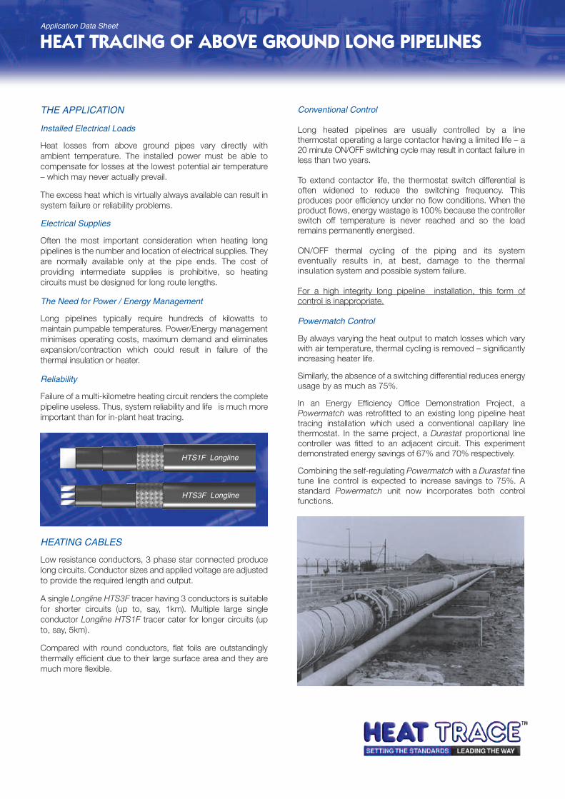
THE APPLICATION
Installed Electrical Loads
Heat losses from above ground pipes vary directly withambient temperature. The installed power must be able tocompensate for losses at the lowest potential air temperature– which may never actually prevail.
The excess heat which is virtually always available can result insystem failure or reliability problems.
Electrical Supplies
Often the most important consideration when heating longpipelines is the number and location of electrical supplies. Theyare normally available only at the pipe ends. The cost ofproviding intermediate supplies is prohibitive, so heatingcircuits must be designed for long route lengths.
The Need for Power / Energy Management
Long pipelines typically require hundreds of kilowatts tomaintain pumpable temperatures. Power/Energy managementminimises operating costs, maximum demand and eliminatesexpansion/contraction which could result in failure of thethermal insulation or heater.
Reliability
Failure of a multi-kilometre heating circuit renders the completepipeline useless. Thus, system reliability and life is much moreimportant than for in-plant heat tracing.
HEATING CABLES
Low resistance conductors, 3 phase star connected producelong circuits. Conductor sizes and applied voltage are adjustedto provide the required length and output.
A single Longline HTS3F tracer having 3 conductors is suitablefor shorter circuits (up to, say, 1km). Multiple large singleconductor Longline HTS1F tracer cater for longer circuits (upto, say, 5km).
Compared with round conductors, flat foils are outstandinglythermally efficient due to their large surface area and they aremuch more flexible.
Conventional Control
Long heated pipelines are usually controlled by a linethermostat operating a large contactor having a limited life – a20 minute ON/OFF switching cycle may result in contact failure inless than two years.
To extend contactor life, the thermostat switch differential isoften widened to reduce the switching frequency. Thisproduces poor efficiency under no flow conditions. When theproduct flows, energy wastage is 100% because the controllerswitch off temperature is never reached and so the loadremains permanently energised.
ON/OFF thermal cycling of the piping and its systemeventually results in, at best, damage to the thermalinsulation system and possible system failure.
For a high integrity long pipeline installation, this form ofcontrol is inappropriate.
Powermatch Control
By always varying the heat output to match losses which varywith air temperature, thermal cycling is removed – significantlyincreasing heater life.
Similarly, the absence of a switching differential reduces energyusage by as much as 75%.
In an Energy Efficiency Office Demonstration Project, aPowermatch was retrofitted to an existing long pipeline heattracing installation which used a conventional capillary linethermostat. In the same project, a Durastat proportional linecontroller was fitted to an adjacent circuit. This experimentdemonstrated energy savings of 67% and 70% respectively.
Combining the self-regulating Powermatch with a Durastat finetune line control is expected to increase savings to 75%. Astandard Powermatch unit now incorporates both controlfunctions.
HEAT TRACING OF ABOVE GROUND LONG PIPELINES
HTS1F Longline
HTS3F Longline
Application Data Sheet
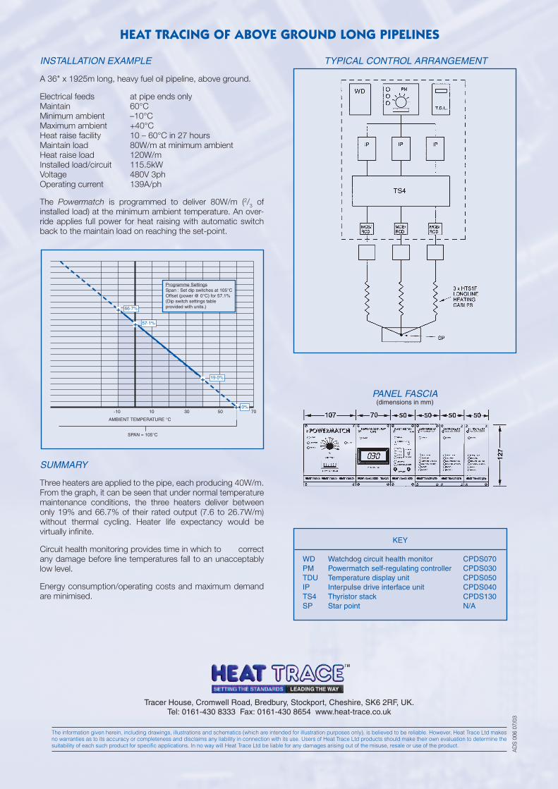
HEAT TRACING OF ABOVE GROUND LONG PIPELINES
Tracer House, Cromwell Road, Bredbury, Stockport, Cheshire, SK6 2RF, UK.Tel: 0161-430 8333 Fax: 0161-430 8654 www.heat-trace.co.uk
The information given herein, including drawings, illustrations and schematics (which are intended for illustration purposes only), is believed to be reliable. However, Heat Trace Ltd makesno warranties as to its accuracy or completeness and disclaims any liability in connection with its use. Users of Heat Trace Ltd products should make their own evaluation to determine thesuitability of each such product for specific applications. In no way will Heat Trace Ltd be liable for any damages arising out of the misuse, resale or use of the product.
AD
S 00
6 07
/03
INSTALLATION EXAMPLE
A 36" x 1925m long, heavy fuel oil pipeline, above ground.
Electrical feeds at pipe ends onlyMaintain 60°CMinimum ambient –10°CMaximum ambient +40°CHeat raise facility 10 – 60°C in 27 hoursMaintain load 80W/m at minimum ambientHeat raise load 120W/mInstalled load/circuit 115.5kWVoltage 480V 3phOperating current 139A/ph
The Powermatch is programmed to deliver 80W/m (2/3 ofinstalled load) at the minimum ambient temperature. An over-ride applies full power for heat raising with automatic switchback to the maintain load on reaching the set-point.
SUMMARY
Three heaters are applied to the pipe, each producing 40W/m.From the graph, it can be seen that under normal temperaturemaintenance conditions, the three heaters deliver betweenonly 19% and 66.7% of their rated output (7.6 to 26.7W/m)without thermal cycling. Heater life expectancy would bevirtually infinite.
Circuit health monitoring provides time in which to correctany damage before line temperatures fall to an unacceptablylow level.
Energy consumption/operating costs and maximum demandare minimised.
KEY
WD Watchdog circuit health monitor CPDS070PM Powermatch self-regulating controller CPDS030TDU Temperature display unit CPDS050IP Interpulse drive interface unit CPDS040TS4 Thyristor stack CPDS130SP Star point N/A
TYPICAL CONTROL ARRANGEMENT
PANEL FASCIA(dimensions in mm)
0%
19·0%
57·1%
66·7%
+
SPAN = 105°C
AMBIENT TEMPERATURE °C
-10 10 30 50 70
+
+
+
Programme SettingsSpan : Set dip switches at 105°COffset (power @ 0°C) for 57.1%(Dip switch settings table provided with units.)
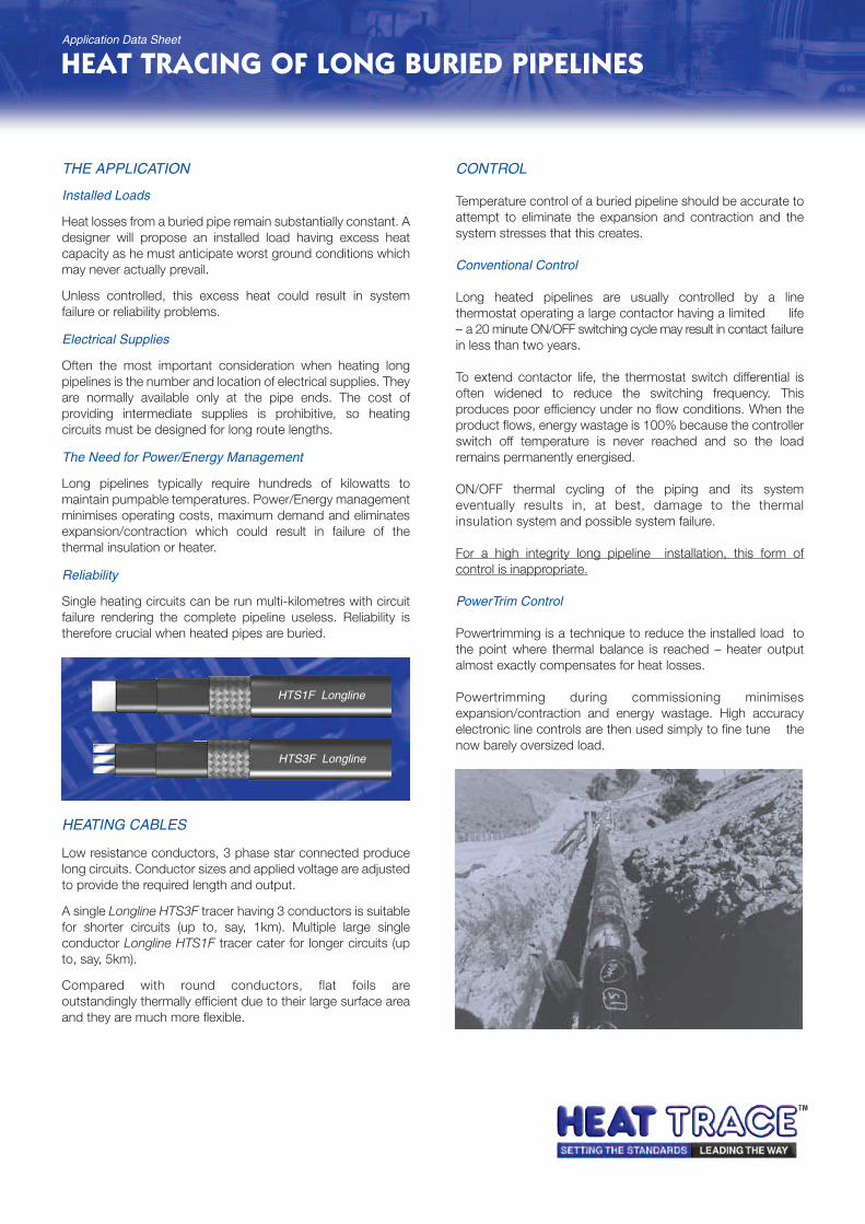
THE APPLICATION
Installed Loads
Heat losses from a buried pipe remain substantially constant. Adesigner will propose an installed load having excess heatcapacity as he must anticipate worst ground conditions whichmay never actually prevail.
Unless controlled, this excess heat could result in systemfailure or reliability problems.
Electrical Supplies
Often the most important consideration when heating longpipelines is the number and location of electrical supplies. Theyare normally available only at the pipe ends. The cost ofproviding intermediate supplies is prohibitive, so heatingcircuits must be designed for long route lengths.
The Need for Power/Energy Management
Long pipelines typically require hundreds of kilowatts tomaintain pumpable temperatures. Power/Energy managementminimises operating costs, maximum demand and eliminatesexpansion/contraction which could result in failure of thethermal insulation or heater.
Reliability
Single heating circuits can be run multi-kilometres with circuitfailure rendering the complete pipeline useless. Reliability istherefore crucial when heated pipes are buried.
HEATING CABLES
Low resistance conductors, 3 phase star connected producelong circuits. Conductor sizes and applied voltage are adjustedto provide the required length and output.
A single Longline HTS3F tracer having 3 conductors is suitablefor shorter circuits (up to, say, 1km). Multiple large singleconductor Longline HTS1F tracer cater for longer circuits (upto, say, 5km).
Compared with round conductors, flat foils areoutstandingly thermally efficient due to their large surface areaand they are much more flexible.
CONTROL
Temperature control of a buried pipeline should be accurate toattempt to eliminate the expansion and contraction and thesystem stresses that this creates.
Conventional Control
Long heated pipelines are usually controlled by a linethermostat operating a large contactor having a limited life– a 20 minute ON/OFF switching cycle may result in contact failurein less than two years.
To extend contactor life, the thermostat switch differential isoften widened to reduce the switching frequency. Thisproduces poor efficiency under no flow conditions. When theproduct flows, energy wastage is 100% because the controllerswitch off temperature is never reached and so the loadremains permanently energised.
ON/OFF thermal cycling of the piping and its systemeventually results in, at best, damage to the thermalinsulation system and possible system failure.
For a high integrity long pipeline installation, this form ofcontrol is inappropriate.
PowerTrim Control
Powertrimming is a technique to reduce the installed load tothe point where thermal balance is reached – heater outputalmost exactly compensates for heat losses.
Powertrimming during commissioning minimisesexpansion/contraction and energy wastage. High accuracyelectronic line controls are then used simply to fine tune thenow barely oversized load.
HEAT TRACING OF LONG BURIED PIPELINES
HTS1F Longline
HTS3F Longline
Application Data Sheet
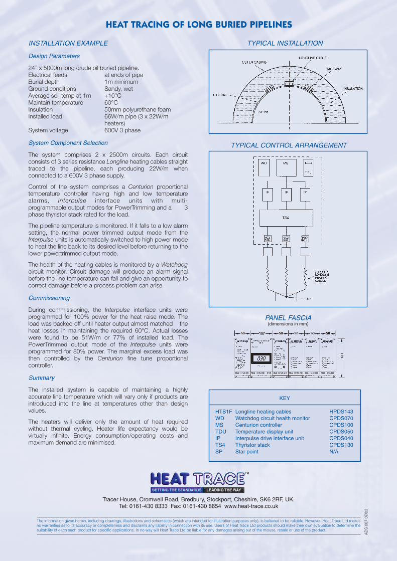
HEAT TRACING OF LONG BURIED PIPELINES
Tracer House, Cromwell Road, Bredbury, Stockport, Cheshire, SK6 2RF, UK.Tel: 0161-430 8333 Fax: 0161-430 8654 www.heat-trace.co.uk
The information given herein, including drawings, illustrations and schematics (which are intended for illustration purposes only), is believed to be reliable. However, Heat Trace Ltd makesno warranties as to its accuracy or completeness and disclaims any liability in connection with its use. Users of Heat Trace Ltd products should make their own evaluation to determine thesuitability of each such product for specific applications. In no way will Heat Trace Ltd be liable for any damages arising out of the misuse, resale or use of the product.
AD
S 00
7 07
/03
INSTALLATION EXAMPLE
Design Parameters
24” x 5000m long crude oil buried pipeline.Electrical feeds at ends of pipeBurial depth 1m minimumGround conditions Sandy, wetAverage soil temp at 1m +10°CMaintain temperature 60°CInsulation 50mm polyurethane foamInstalled load 66W/m pipe (3 x 22W/m
heaters)System voltage 600V 3 phase
System Component Selection
The system comprises 2 x 2500m circuits. Each circuitconsists of 3 series resistance Longline heating cables straighttraced to the pipeline, each producing 22W/m whenconnected to a 600V 3 phase supply.
Control of the system comprises a Centurion proportionaltemperature controller having high and low temperaturealarms, Interpulse interface units with multi-programmable output modes for PowerTrimming and a 3phase thyristor stack rated for the load.
The pipeline temperature is monitored. If it falls to a low alarmsetting, the normal power trimmed output mode from theInterpulse units is automatically switched to high power modeto heat the line back to its desired level before returning to thelower powertrimmed output mode.
The health of the heating cables is monitored by a Watchdogcircuit monitor. Circuit damage will produce an alarm signalbefore the line temperature can fall and give an opportunity tocorrect damage before a process problem can arise.
Commissioning
During commissioning, the Interpulse interface units wereprogrammed for 100% power for the heat raise mode. Theload was backed off until heater output almost matched theheat losses in maintaining the required 60°C. Actual losseswere found to be 51W/m or 77% of installed load. ThePowerTrimmed output mode of the Interpulse units wereprogrammed for 80% power. The marginal excess load wasthen controlled by the Centurion fine tune proportionalcontroller.
Summary
The installed system is capable of maintaining a highlyaccurate line temperature which will vary only if products areintroduced into the line at temperatures other than designvalues.
The heaters will deliver only the amount of heat requiredwithout thermal cycling. Heater life expectancy would bevirtually infinite. Energy consumption/operating costs andmaximum demand are minimised.
KEY
HTS1F Longline heating cables HPDS143WD Watchdog circuit health monitor CPDS070MS Centurion controller CPDS100TDU Temperature display unit CPDS050IP Interpulse drive interface unit CPDS040TS4 Thyristor stack CPDS130SP Star point N/A
TYPICAL INSTALLATION
TYPICAL CONTROL ARRANGEMENT
PANEL FASCIA(dimensions in mm)
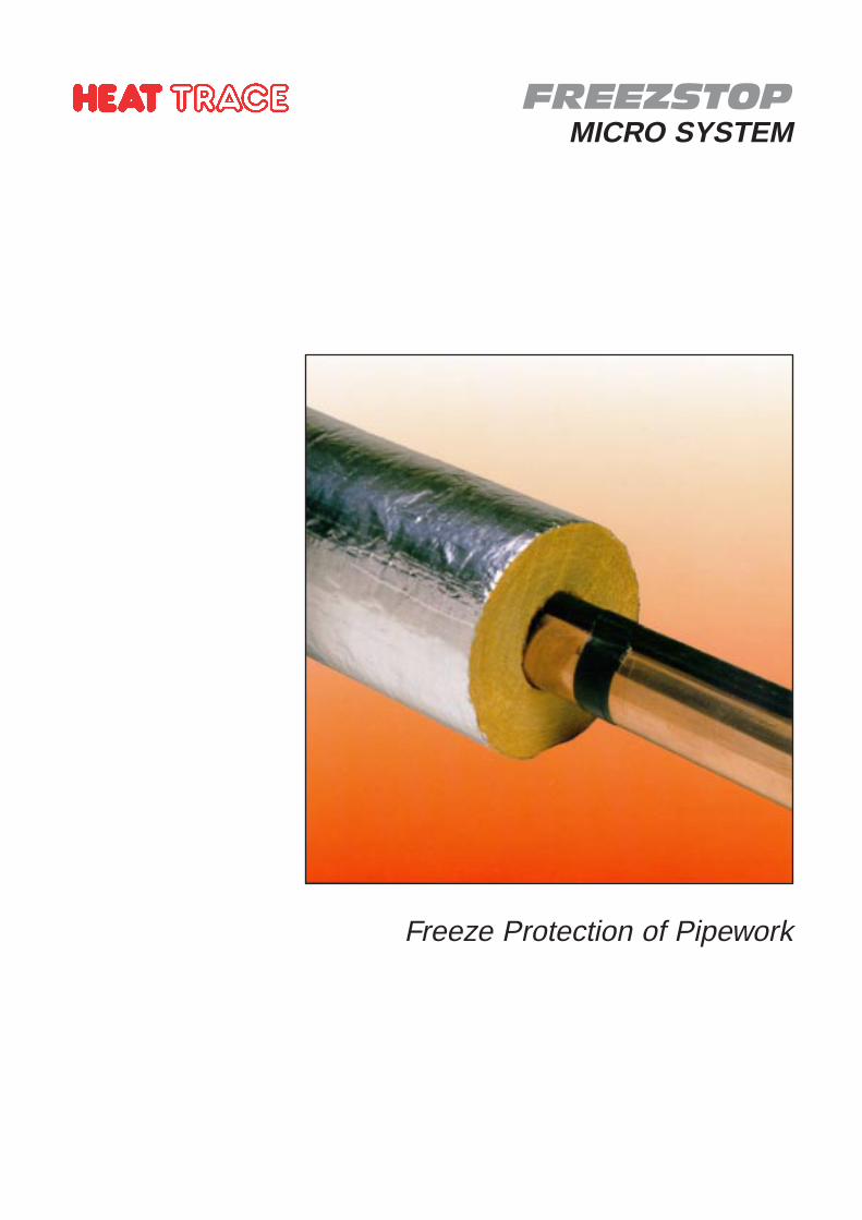
FREEZSTOPMICRO SYSTEM
Freeze Protection of Pipework
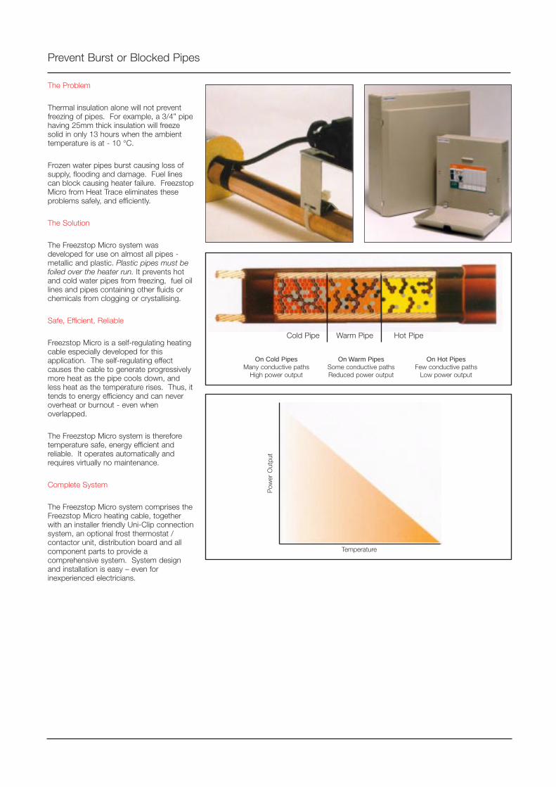
The Problem
Thermal insulation alone will not preventfreezing of pipes. For example, a 3/4” pipehaving 25mm thick insulation will freezesolid in only 13 hours when the ambienttemperature is at - 10 °C.
Frozen water pipes burst causing loss ofsupply, flooding and damage. Fuel linescan block causing heater failure. FreezstopMicro from Heat Trace eliminates theseproblems safely, and efficiently.
The Solution
The Freezstop Micro system wasdeveloped for use on almost all pipes -metallic and plastic. Plastic pipes must befoiled over the heater run. It prevents hotand cold water pipes from freezing, fuel oillines and pipes containing other fluids orchemicals from clogging or crystallising.
Safe, Efficient, Reliable
Freezstop Micro is a self-regulating heatingcable especially developed for thisapplication. The self-regulating effectcauses the cable to generate progressivelymore heat as the pipe cools down, andless heat as the temperature rises. Thus, ittends to energy efficiency and can neveroverheat or burnout - even whenoverlapped.
The Freezstop Micro system is thereforetemperature safe, energy efficient andreliable. It operates automatically andrequires virtually no maintenance.
Complete System
The Freezstop Micro system comprises theFreezstop Micro heating cable, togetherwith an installer friendly Uni-Clip connectionsystem, an optional frost thermostat /contactor unit, distribution board and allcomponent parts to provide acomprehensive system. System designand installation is easy – even forinexperienced electricians.
Prevent Burst or Blocked Pipes
On Cold PipesMany conductive paths
High power output
On Warm PipesSome conductive pathsReduced power output
On Hot PipesFew conductive paths
Low power output
Temperature
Pow
er O
utpu
t
Cold Pipe Warm Pipe Hot Pipe
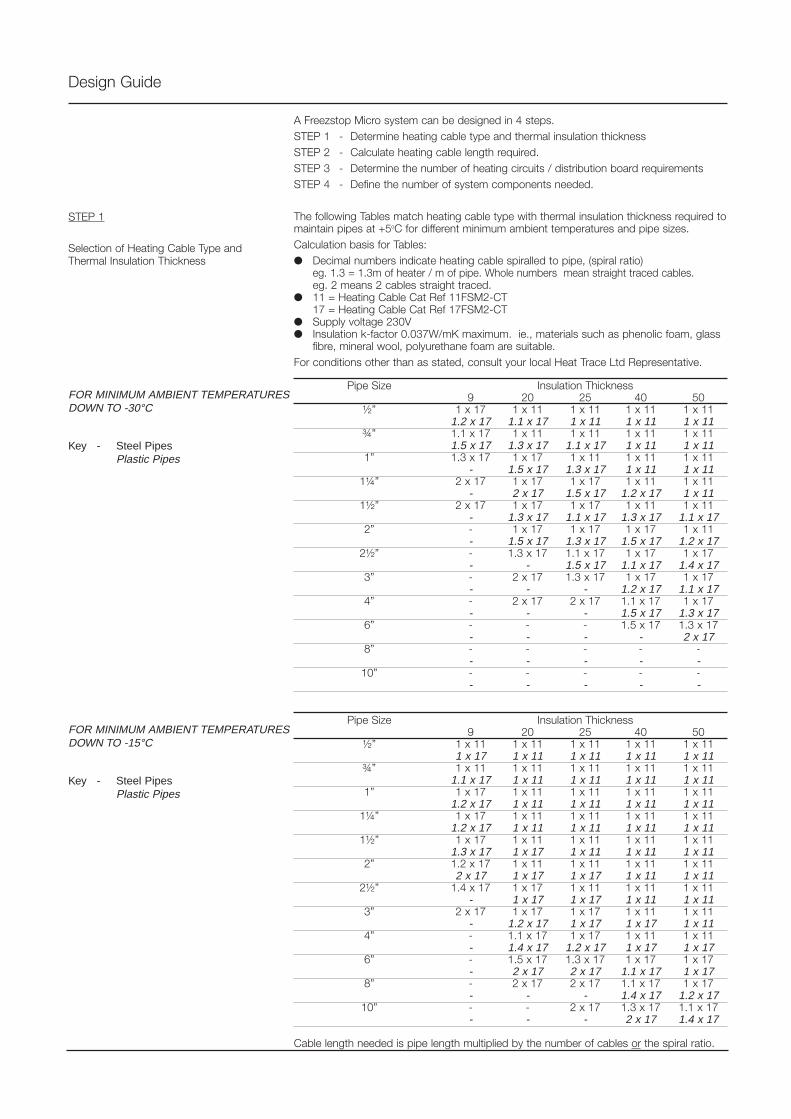
A Freezstop Micro system can be designed in 4 steps.STEP 1 - Determine heating cable type and thermal insulation thicknessSTEP 2 - Calculate heating cable length required.STEP 3 - Determine the number of heating circuits / distribution board requirementsSTEP 4 - Define the number of system components needed.
The following Tables match heating cable type with thermal insulation thickness required tomaintain pipes at +5oC for different minimum ambient temperatures and pipe sizes.Calculation basis for Tables: Decimal numbers indicate heating cable spiralled to pipe, (spiral ratio)
eg. 1.3 = 1.3m of heater / m of pipe. Whole numbers mean straight traced cables.eg. 2 means 2 cables straight traced.
11 = Heating Cable Cat Ref 11FSM2-CT17 = Heating Cable Cat Ref 17FSM2-CT
Supply voltage 230V Insulation k-factor 0.037W/mK maximum. ie., materials such as phenolic foam, glass
fibre, mineral wool, polyurethane foam are suitable.For conditions other than as stated, consult your local Heat Trace Ltd Representative.
Pipe Size Insulation Thickness9 20 25 40 50
½” 1 x 17 1 x 11 1 x 11 1 x 11 1 x 111.2 x 17 1.1 x 17 1 x 11 1 x 11 1 x 11
¾” 1.1 x 17 1 x 11 1 x 11 1 x 11 1 x 111.5 x 17 1.3 x 17 1.1 x 17 1 x 11 1 x 11
1” 1.3 x 17 1 x 17 1 x 11 1 x 11 1 x 11- 1.5 x 17 1.3 x 17 1 x 11 1 x 11
1¼” 2 x 17 1 x 17 1 x 17 1 x 11 1 x 11- 2 x 17 1.5 x 17 1.2 x 17 1 x 11
1½” 2 x 17 1 x 17 1 x 17 1 x 11 1 x 11- 1.3 x 17 1.1 x 17 1.3 x 17 1.1 x 17
2” - 1 x 17 1 x 17 1 x 17 1 x 11- 1.5 x 17 1.3 x 17 1.5 x 17 1.2 x 17
2½” - 1.3 x 17 1.1 x 17 1 x 17 1 x 17- - 1.5 x 17 1.1 x 17 1.4 x 17
3” - 2 x 17 1.3 x 17 1 x 17 1 x 17- - - 1.2 x 17 1.1 x 17
4” - 2 x 17 2 x 17 1.1 x 17 1 x 17- - - 1.5 x 17 1.3 x 17
6” - - - 1.5 x 17 1.3 x 17- - - - 2 x 17
8” - - - - -- - - - -
10” - - - - -- - - - -
Pipe Size Insulation Thickness9 20 25 40 50
½” 1 x 11 1 x 11 1 x 11 1 x 11 1 x 111 x 17 1 x 11 1 x 11 1 x 11 1 x 11
¾” 1 x 11 1 x 11 1 x 11 1 x 11 1 x 111.1 x 17 1 x 11 1 x 11 1 x 11 1 x 11
1” 1 x 17 1 x 11 1 x 11 1 x 11 1 x 111.2 x 17 1 x 11 1 x 11 1 x 11 1 x 11
1¼” 1 x 17 1 x 11 1 x 11 1 x 11 1 x 111.2 x 17 1 x 11 1 x 11 1 x 11 1 x 11
1½” 1 x 17 1 x 11 1 x 11 1 x 11 1 x 111.3 x 17 1 x 17 1 x 11 1 x 11 1 x 11
2” 1.2 x 17 1 x 11 1 x 11 1 x 11 1 x 112 x 17 1 x 17 1 x 17 1 x 11 1 x 11
2½” 1.4 x 17 1 x 17 1 x 11 1 x 11 1 x 11- 1 x 17 1 x 17 1 x 11 1 x 11
3” 2 x 17 1 x 17 1 x 17 1 x 11 1 x 11- 1.2 x 17 1 x 17 1 x 17 1 x 11
4” - 1.1 x 17 1 x 17 1 x 11 1 x 11- 1.4 x 17 1.2 x 17 1 x 17 1 x 17
6” - 1.5 x 17 1.3 x 17 1 x 17 1 x 17- 2 x 17 2 x 17 1.1 x 17 1 x 17
8” - 2 x 17 2 x 17 1.1 x 17 1 x 17- - - 1.4 x 17 1.2 x 17
10” - - 2 x 17 1.3 x 17 1.1 x 17- - - 2 x 17 1.4 x 17
Cable length needed is pipe length multiplied by the number of cables or the spiral ratio.
Design Guide
STEP 1
Selection of Heating Cable Type andThermal Insulation Thickness
Key - Steel PipesPlastic Pipes
FOR MINIMUM AMBIENT TEMPERATURESDOWN TO -15°C
FOR MINIMUM AMBIENT TEMPERATURESDOWN TO -30°C
Key - Steel PipesPlastic Pipes
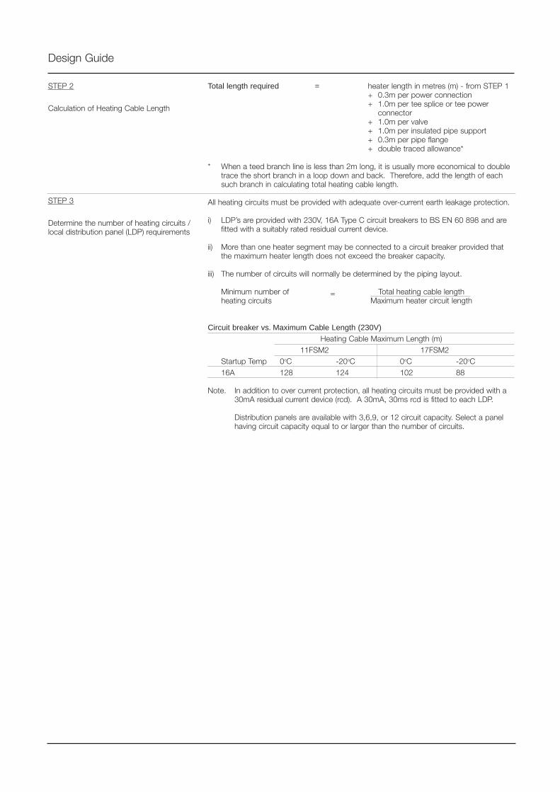
Design Guide
STEP 2
Calculation of Heating Cable Length
Total length required = heater length in metres (m) - from STEP 1+ 0.3m per power connection+ 1.0m per tee splice or tee power
connector+ 1.0m per valve+ 1.0m per insulated pipe support+ 0.3m per pipe flange+ double traced allowance*
* When a teed branch line is less than 2m long, it is usually more economical to doubletrace the short branch in a loop down and back. Therefore, add the length of eachsuch branch in calculating total heating cable length.
All heating circuits must be provided with adequate over-current earth leakage protection.
i) LDP’s are provided with 230V, 16A Type C circuit breakers to BS EN 60 898 and arefitted with a suitably rated residual current device.
ii) More than one heater segment may be connected to a circuit breaker provided thatthe maximum heater length does not exceed the breaker capacity.
iii) The number of circuits will normally be determined by the piping layout.
Minimum number of Total heating cable lengthheating circuits Maximum heater circuit length
Circuit breaker vs. Maximum Cable Length (230V)
Heating Cable Maximum Length (m)11FSM2 17FSM2
Startup Temp 0oC -20oC 0oC -20oC16A 128 124 102 88
Note. In addition to over current protection, all heating circuits must be provided with a30mA residual current device (rcd). A 30mA, 30ms rcd is fitted to each LDP.
Distribution panels are available with 3,6,9, or 12 circuit capacity. Select a panelhaving circuit capacity equal to or larger than the number of circuits.
STEP 3
Determine the number of heating circuits /local distribution panel (LDP) requirements
=
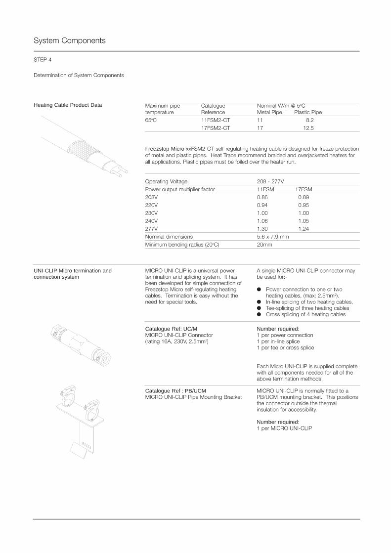
System Components
UNI-CLIP Micro termination andconnection system
MICRO UNI-CLIP is a universal powertermination and splicing system. It hasbeen developed for simple connection ofFreezstop Micro self-regulating heatingcables. Termination is easy without theneed for special tools.
A single MICRO UNI-CLIP connector maybe used for:-
Power connection to one or twoheating cables, (max: 2.5mm²).
In-line splicing of two heating cables, Tee-splicing of three heating cables Cross splicing of 4 heating cables
Catalogue Ref: UC/MMICRO UNI-CLIP Connector(rating 16A, 230V, 2.5mm2)
Catalogue Ref : PB/UCMMICRO UNI-CLIP Pipe Mounting Bracket
Number required:1 per power connection1 per in-line splice1 per tee or cross splice
Each Micro UNI-CLIP is supplied completewith all components needed for all of theabove termination methods.
MICRO UNI-CLIP is normally fitted to aPB/UCM mounting bracket. This positionsthe connector outside the thermalinsulation for accessibility.
Number required:1 per MICRO UNI-CLIP
Heating Cable Product Data Maximum pipe Catalogue Nominal W/m @ 5oCtemperature Reference Metal Pipe Plastic Pipe65oC 11FSM2-CT 11 8.2
17FSM2-CT 17 12.5
Freezstop Micro xxFSM2-CT self-regulating heating cable is designed for freeze protectionof metal and plastic pipes. Heat Trace recommend braided and overjacketed heaters forall applications. Plastic pipes must be foiled over the heater run.
Operating Voltage 208 - 277VPower output multiplier factor 11FSM 17FSM208V 0.86 0.89220V 0.94 0.95230V 1.00 1.00240V 1.06 1.05277V 1.30 1.24Nominal dimensions 5.6 x 7.9 mmMinimum bending radius (20oC) 20mm
STEP 4
Determination of System Components

System Components
Catalogue Ref : PFSxxx or NT/SF The PB/UCM is fitted to pipework up to50mm bore with cable ties provided withthe PB/UCM. For larger pipes, pipe fixingstraps are required as follows.
PFS050 for pipes <= 125mm diameterPFS100 for pipes <= 250mm diameter
Number required:1 per PB/UCM
Catalogue Ref : FT/HTP Fixing tape is used to hold the FreezstopMicro heating cable in position on metalpipes.
Number required: FT/HTP rolls per 100m of pipeworkNominal Bore ins. 1/2 1 1.5 2 3 4 6 8of Pipe mm 15 25 40 50 75 100 150 200Straight Traced rolls 2 3 4 5 7 10 15 20Spiraled rolls 1 1 1 2 2 2 3 4
Catalogue Ref : FT/ALUM Fixing tape is fitted over Freezstop Microheating cable on plastic pipes
Number required:1 roll per 45m of heating tape
Catalogue Ref : LEK/U For exiting the Freezstop Micro heatingcable from the thermal insulation. Used foroutdoor installations, for sealing cable exitpoints to prevent rain ingress.
Number required:1 per cable exit at tees,power connection, etc.
Catalogue Ref : CL ‘Electric Heat Traced’ warning label forfixing at 6m intervals to the outside of theinsulation cladding.
Number required:1 label every 6m of traced pipework
Catalogue Ref : BES1 Silicone rubber end seal for sealing theremote ends of the heating tape.
Number required:1 per cable end
Pipe Fixing Straps
PVC Fixing Tape
Aluminium Fixing Tape
Lagging Entry Kit
Caution Labels
End Seal
Catalogue Ref : RTV0.5 For fixing end seal BES1 to end of theatingcable.
Number required:1 per 5 end seals
End Seal Adhesive
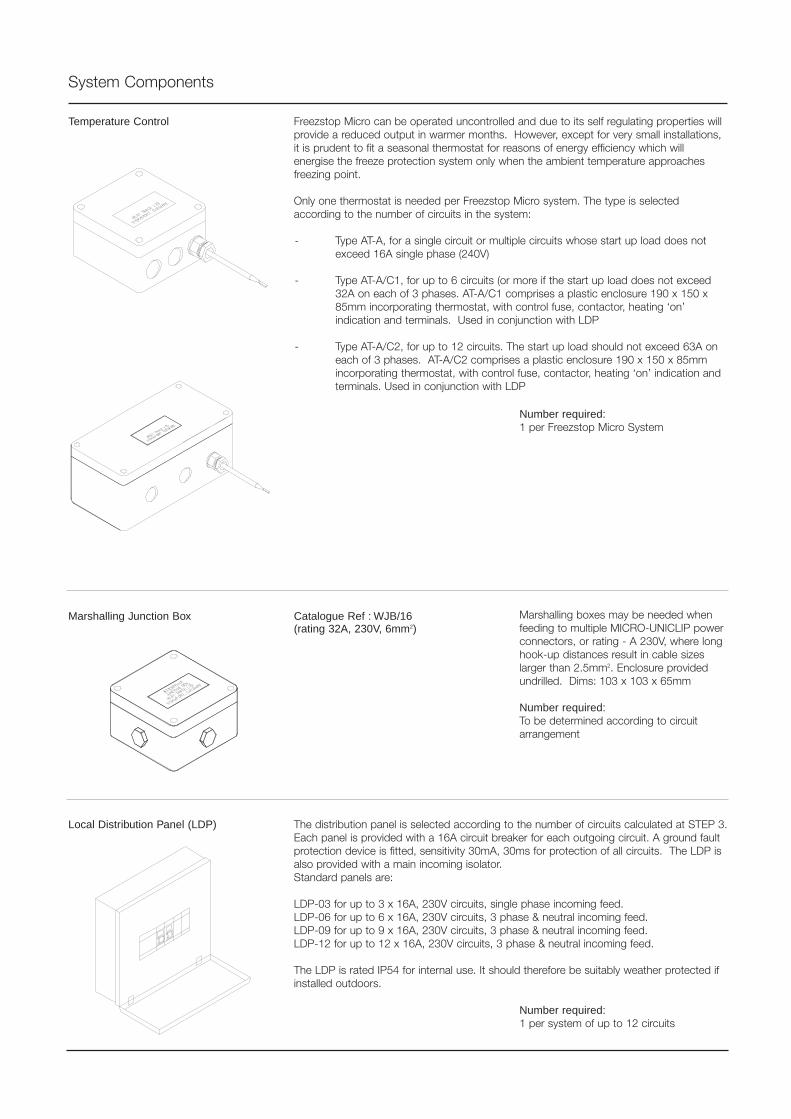
System Components
Temperature Control Freezstop Micro can be operated uncontrolled and due to its self regulating properties willprovide a reduced output in warmer months. However, except for very small installations,it is prudent to fit a seasonal thermostat for reasons of energy efficiency which willenergise the freeze protection system only when the ambient temperature approachesfreezing point.
Only one thermostat is needed per Freezstop Micro system. The type is selectedaccording to the number of circuits in the system:
- Type AT-A, for a single circuit or multiple circuits whose start up load does notexceed 16A single phase (240V)
- Type AT-A/C1, for up to 6 circuits (or more if the start up load does not exceed32A on each of 3 phases. AT-A/C1 comprises a plastic enclosure 190 x 150 x85mm incorporating thermostat, with control fuse, contactor, heating ‘on’indication and terminals. Used in conjunction with LDP
- Type AT-A/C2, for up to 12 circuits. The start up load should not exceed 63A oneach of 3 phases. AT-A/C2 comprises a plastic enclosure 190 x 150 x 85mmincorporating thermostat, with control fuse, contactor, heating ‘on’ indication andterminals. Used in conjunction with LDP
Local Distribution Panel (LDP) The distribution panel is selected according to the number of circuits calculated at STEP 3.Each panel is provided with a 16A circuit breaker for each outgoing circuit. A ground faultprotection device is fitted, sensitivity 30mA, 30ms for protection of all circuits. The LDP isalso provided with a main incoming isolator.Standard panels are:
LDP-03 for up to 3 x 16A, 230V circuits, single phase incoming feed.LDP-06 for up to 6 x 16A, 230V circuits, 3 phase & neutral incoming feed.LDP-09 for up to 9 x 16A, 230V circuits, 3 phase & neutral incoming feed.LDP-12 for up to 12 x 16A, 230V circuits, 3 phase & neutral incoming feed.
The LDP is rated IP54 for internal use. It should therefore be suitably weather protected ifinstalled outdoors.
Marshalling boxes may be needed whenfeeding to multiple MICRO-UNICLIP powerconnectors, or rating - A 230V, where longhook-up distances result in cable sizeslarger than 2.5mm2. Enclosure providedundrilled. Dims: 103 x 103 x 65mm
Number required:To be determined according to circuitarrangement
Marshalling Junction Box Catalogue Ref : WJB/16(rating 32A, 230V, 6mm2)
Number required:1 per Freezstop Micro System
Number required:1 per system of up to 12 circuits
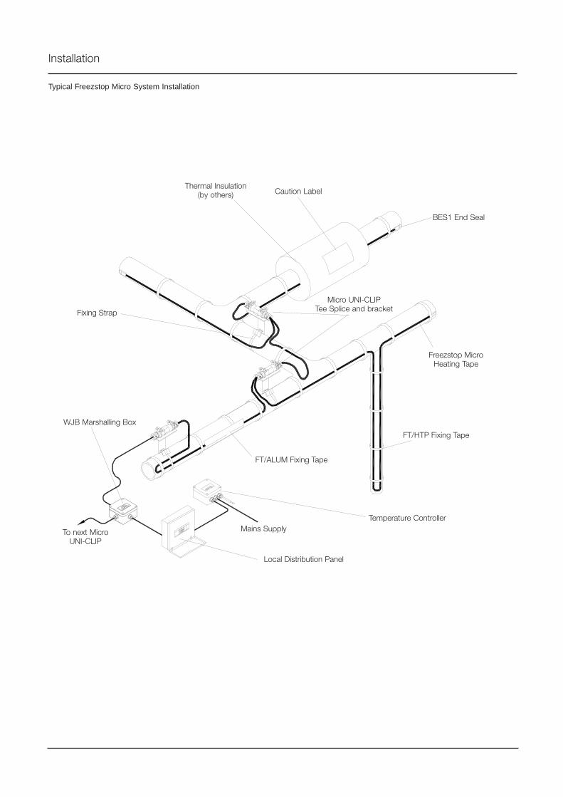
Typical Freezstop Micro System Installation
BES1 End Seal
Micro UNI-CLIPTee Splice and bracket
Local Distribution Panel
FT/HTP Fixing Tape
FT/ALUM Fixing Tape
Freezstop MicroHeating Tape
Caution Label
Fixing Strap
Thermal Insulation(by others)
Installation
Temperature ControllerMains Supply
WJB Marshalling Box
To next MicroUNI-CLIP
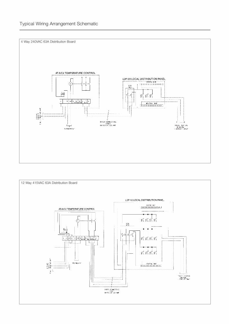
Typical Wiring Arrangement Schematic
4 Way 240VAC 63A Distribution Board
12 Way 415VAC 63A Distribution Board
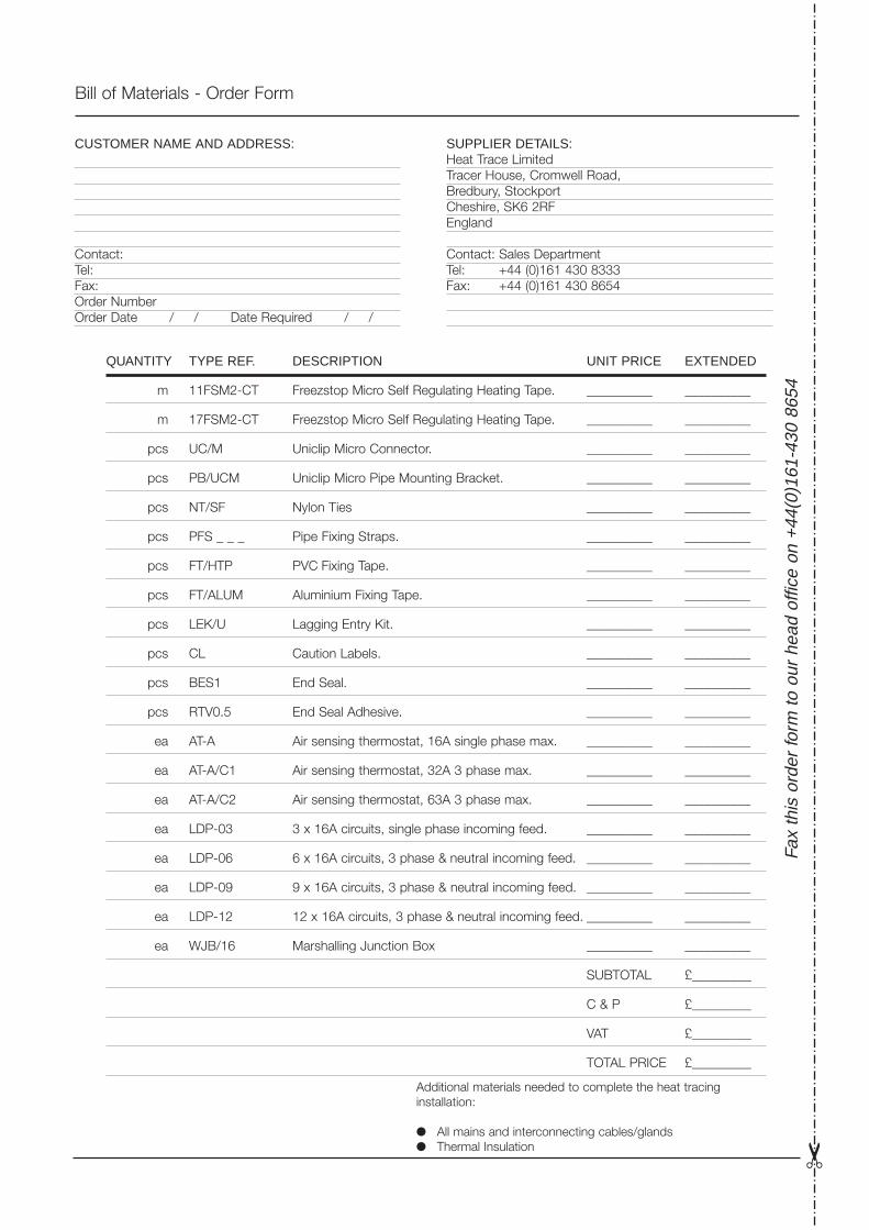
Bill of Materials - Order Form
Fa
x th
is o
rder
form
to o
ur h
ead
offic
e on
+44
(0)1
61-4
30 8
654
Additional materials needed to complete the heat tracinginstallation:
All mains and interconnecting cables/glands Thermal Insulation
QUANTITY TYPE REF. DESCRIPTION UNIT PRICE EXTENDED
m 11FSM2-CT Freezstop Micro Self Regulating Heating Tape. __________ __________
m 17FSM2-CT Freezstop Micro Self Regulating Heating Tape. __________ __________
pcs UC/M Uniclip Micro Connector. __________ __________
pcs PB/UCM Uniclip Micro Pipe Mounting Bracket. __________ __________
pcs NT/SF Nylon Ties __________ __________
pcs PFS _ _ _ Pipe Fixing Straps. __________ __________
pcs FT/HTP PVC Fixing Tape. __________ __________
pcs FT/ALUM Aluminium Fixing Tape. __________ __________
pcs LEK/U Lagging Entry Kit. __________ __________
pcs CL Caution Labels. __________ __________
pcs BES1 End Seal. __________ __________
pcs RTV0.5 End Seal Adhesive. __________ __________
ea AT-A Air sensing thermostat, 16A single phase max. __________ __________
ea AT-A/C1 Air sensing thermostat, 32A 3 phase max. __________ __________
ea AT-A/C2 Air sensing thermostat, 63A 3 phase max. __________ __________
ea LDP-03 3 x 16A circuits, single phase incoming feed. __________ __________
ea LDP-06 6 x 16A circuits, 3 phase & neutral incoming feed. __________ __________
ea LDP-09 9 x 16A circuits, 3 phase & neutral incoming feed. __________ __________
ea LDP-12 12 x 16A circuits, 3 phase & neutral incoming feed. __________ __________
ea WJB/16 Marshalling Junction Box __________ __________
SUBTOTAL £_________
C & P £_________
VAT £_________
TOTAL PRICE £_________
CUSTOMER NAME AND ADDRESS:
Contact:Tel:Fax:Order NumberOrder Date / / Date Required / /
SUPPLIER DETAILS:Heat Trace LimitedTracer House, Cromwell Road,Bredbury, StockportCheshire, SK6 2RFEngland
Contact: Sales DepartmentTel: +44 (0)161 430 8333Fax: +44 (0)161 430 8654
System Layout

Tracer House, Cromwell Road, Bredbury, Stockport, Cheshire, SK6 2RF, U.K.Tel: +44(0)161-430 8333 Fax: +44(0)161-430 8654 http://www.heat-trace.ltd.uk
The information given herein, including drawings, illustrations and schematics (which are intended for illustration purposes only), is believed to be reliable. However, Heat Trace Ltd makes nowarranties as to its accuracy or completeness and disclaims any liability in connection with its use. Users of Heat Trace Ltd products should make their own evaluation to determine the suitabilityof each such product for specific applications. In no way will Heat Trace Ltd be liable for any damages arising out of the misuse, resale or use of the product.
PD
G03
0 12
/98
draf
t
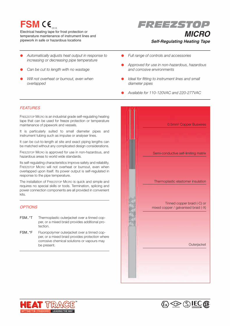
FREEZSTOPMICRO
Self-Regulating Heating Tape
FSMElectrical heating tape for frost protection ortemperature maintenance of instrument lines andpipework in safe or hazardous locations
FEATURES
FREEZSTOP MICRO is an industrial grade self-regulating heatingtape that can be used for freeze protection or temperaturemaintenance of pipework and vessels.
It is particularly suited to small diameter pipes andinstrument tubing such as impulse or analyser lines.
It can be cut-to-length at site and exact piping lengths canbe matched without any complicated design considerations.
FREEZSTOP MICRO is approved for use in non-hazardous, andhazardous areas to world wide standards.
Its self-regulating characteristics improve safety and reliability.FREEZSTOP MICRO will not overheat or burnout, even whenoverlapped upon itself. Its power output is self-regulated inresponse to the pipe temperature.
The installation of FREEZSTOP MICRO is quick and simple andrequires no special skills or tools. Termination, splicing andpower connection components are all provided in convenientkits.
OPTIONS
FSM..*T Thermoplastic outerjacket over a tinned cop-per, or a mixed braid provides additional pro-tection.
FSM..*F Fluoropolymer outerjacket over a tinned cop-per, or a mixed braid provides protection wherecorrosive chemical solutions or vapours maybe present.
Automatically adjusts heat output in response toincreasing or decreasing pipe temperature
Can be cut to length with no wastage
Will not overheat or burnout, even whenoverlapped
Full range of controls and accessories
Approved for use in non-hazardous, hazardousand corrosive environments
Ideal for fitting to instrument lines and smalldiameter pipes
Available for 110-120VAC and 220-277VAC
0.5mm2 Copper Buswires
Semi-conductive self-limiting matrix
Thermoplastic elastomer insulation
Tinned copper braid (-C) ormixed copper / galvanised braid (-X)
Outerjacket
0518
F M
APPROVED
R
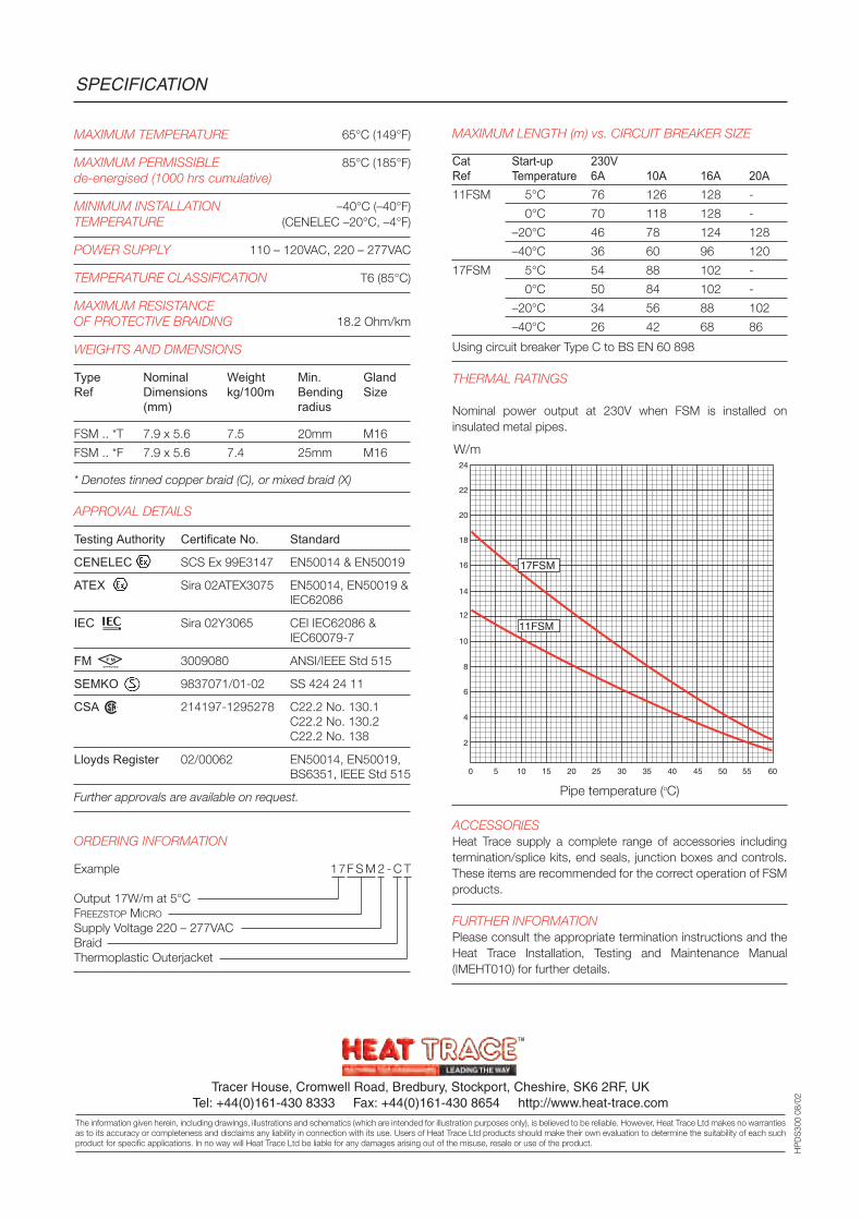
MAXIMUM LENGTH (m) vs. CIRCUIT BREAKER SIZE
Cat Start-up 230VRef Temperature 6A 10A 16A 20A11FSM 5°C 76 126 128 -
0°C 70 118 128 -
–20°C 46 78 124 128
–40°C 36 60 96 120
17FSM 5°C 54 88 102 -
0°C 50 84 102 -
–20°C 34 56 88 102
–40°C 26 42 68 86
Using circuit breaker Type C to BS EN 60 898
THERMAL RATINGS
Nominal power output at 230V when FSM is installed oninsulated metal pipes.
ACCESSORIESHeat Trace supply a complete range of accessories includingtermination/splice kits, end seals, junction boxes and controls.These items are recommended for the correct operation of FSMproducts.
FURTHER INFORMATIONPlease consult the appropriate termination instructions and theHeat Trace Installation, Testing and Maintenance Manual(IMEHT010) for further details.
SPECIFICATION
Tracer House, Cromwell Road, Bredbury, Stockport, Cheshire, SK6 2RF, UKTel: +44(0)161-430 8333 Fax: +44(0)161-430 8654 http://www.heat-trace.com
The information given herein, including drawings, illustrations and schematics (which are intended for illustration purposes only), is believed to be reliable. However, Heat Trace Ltd makes no warrantiesas to its accuracy or completeness and disclaims any liability in connection with its use. Users of Heat Trace Ltd products should make their own evaluation to determine the suitability of each suchproduct for specific applications. In no way will Heat Trace Ltd be liable for any damages arising out of the misuse, resale or use of the product.
HP
DS
300
08/0
2
MAXIMUM TEMPERATURE 65°C (149°F)
MAXIMUM PERMISSIBLE 85°C (185°F)de-energised (1000 hrs cumulative)
MINIMUM INSTALLATION –40°C (–40°F)TEMPERATURE (CENELEC –20°C, –4°F)
POWER SUPPLY 110 – 120VAC, 220 – 277VAC
TEMPERATURE CLASSIFICATION T6 (85°C)
MAXIMUM RESISTANCEOF PROTECTIVE BRAIDING 18.2 Ohm/km
WEIGHTS AND DIMENSIONS
Type Nominal Weight Min. GlandRef Dimensions kg/100m Bending Size
(mm) radius
FSM .. *T 7.9 x 5.6 7.5 20mm M16
FSM .. *F 7.9 x 5.6 7.4 25mm M16
* Denotes tinned copper braid (C), or mixed braid (X)
APPROVAL DETAILS
Testing Authority Certificate No. Standard
CENELEC SCS Ex 99E3147 EN50014 & EN50019
ATEX Sira 02ATEX3075 EN50014, EN50019 &IEC62086
IEC Sira 02Y3065 CEI IEC62086 &IEC60079-7
FM 3009080 ANSI/IEEE Std 515
SEMKO 9837071/01-02 SS 424 24 11
CSA 214197-1295278 C22.2 No. 130.1C22.2 No. 130.2C22.2 No. 138
Lloyds Register 02/00062 EN50014, EN50019,BS6351, IEEE Std 515
Further approvals are available on request.
ORDERING INFORMATION
Example 17F S M 2 - C T
Output 17W/m at 5°CFREEZSTOP MICRO
Supply Voltage 220 – 277VACBraidThermoplastic Outerjacket
0 5
2
4
6
8
10
12
14
18
20
22
24
16
10 15 20 25 30 35 40 45 6050 55
17FSM
11FSM
W/m
Pipe temperature (oC)
F M
APPROVED
R

HOTWATInstant Hot Water System
HOTWAT REGULARSimple, uncontrolled systems
HOTWAT PLUSA high integrity engineered system
for larger installations

Modern living dictates that buildings shallhave hot water available whenever andwherever needed – and preferablyinstantaneously.
Hot water is normally provided by a boiler ina centralised or localised heating system.
After draw off of hot water at a supplypoint, the pipe feeding that supply pointremains full of hot water which, under staticconditions, cools to ambient conditions.
When demand resumes, there is a delayperiod whilst the now cold water isreplaced by water heated from the boiler.The delay is both frustrating and costly, asthe volume of the static head of water musteffectively be heated each time a tap orvalve is opened.
INSTANT HOT WATERTraditional re-circulating system
Virtual instant hot water at taps wasprovided by a twin flow and returnre-circulation system. The length of dead-legs was minimised so that hot waterflowed soon after opening the tap, and sowastage was reduced.
This system has numerous shortcomings:
the flow/return re-circulating pipeworkand thermal insulation has twice thecapital and insulation costs comparedwith a single pipe system.
heat losses from the flow/return re-circulation system are twice those of asingle pipe system.
maintenance costs are incurred with theintroduction of pumps and other itemshaving moving parts.
dual pipe systems require twice thespace.
the system must be balanced.
The Need for Instant Hot Water
HOTWATInstant hot water by single pipe hot watertemperature maintenance
The HOTWAT single pipe temperaturemaintenance system overcomes ALL of theshortcomings of the re-circulation system.
The HOTWAT self-regulating heating cable isfitted to a single hot water supply pipe tomaintain the hot water temperature bycompensating for heat losses underno-flow conditions. Compared with are-circulation system, this results in:
Reduced Capital Costs
half the capital/installation costs ofpipework/thermal insulation (the cost ofthe heat tracing system will usually beless than this saving).
Reduced Operating Costs
half the pipework equals half the heatlosses.
maintenance free (no moving parts).
half the space.
no balancing required.
POWERTRIMMINGVariable temperature settings
Greater system flexibility is provided by theaddition of variable system temperaturesettings. Where required, different parts ofthe building can be programmed tomaintain different temperatures. Control isprovided by a technique known asPowertrimming.
D-BUGThermal pasteurisation
The HOTWAT system can also be providedwith D-BUG, a pasteurisation processwhereby the static pipework system isperiodically raised in temperature todisinfect the system.
Disinfection can be carried outautomatically or manually.
CRUSADERCircuit temperature scanning
The system control panel can include aCRUSADER circuit digital temperaturescanning system to ensure optimum energyefficiency and power trim settings.
BMS INTEGRATION
HOTWAT can be tied into a BMS (BuildingManagement System) for programmedtemperature changes or thermalpasteurisation.
LEGIONELLAHOTWAT reduces risks
Guidance to minimising the risk ofLegionnaires disease is provided in Codesof Practice issued by the HSE (DocumentHS(G)70), CIBSE (TM3) and NHS EstatesTM.2040.
The subject of heat tracing to reduce risksis addressed and in particularpasteurisation of the system by heat raisingabove the temperature at which bacteria isinstantly killed is recommended by the HSECode.
HOTWAT PLUS heating cable with HeatTrace’s D-BUG timed thermalpasteurisation provides such a facility.
2
ECONOMICS POINT TO HOTWAT
Capital costs
The average 80% savings in theinstallation time and costs of a single pipeHOTWAT system will normally result in anoverall capital investment saving of10 – 25% compared with a re-circulationsystem.
CostsRe-Circulation System
Hotwat System
Operating costs
Half the pipework operating at reducedmaintenance temperatures reducesenergy consumption by an average 60%.Even allowing for higher fuel costs, totaloperating costs of a single pipe HOTWAT
system will be 20 – 30% less than anequivalent re-circulation system.
CostsRe-Circulation System
Hotwat System
Materials Labour
Materials SavingsLabour
Savings
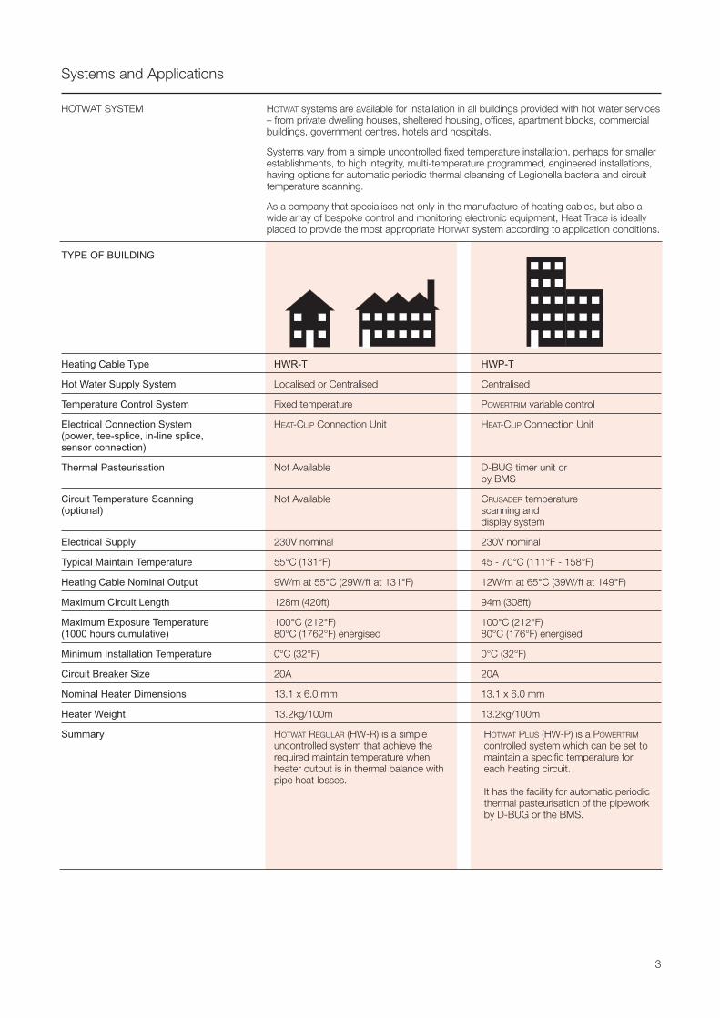
Systems and Applications
HOTWAT systems are available for installation in all buildings provided with hot water services– from private dwelling houses, sheltered housing, offices, apartment blocks, commercialbuildings, government centres, hotels and hospitals.
Systems vary from a simple uncontrolled fixed temperature installation, perhaps for smallerestablishments, to high integrity, multi-temperature programmed, engineered installations,having options for automatic periodic thermal cleansing of Legionella bacteria and circuittemperature scanning.
As a company that specialises not only in the manufacture of heating cables, but also awide array of bespoke control and monitoring electronic equipment, Heat Trace is ideallyplaced to provide the most appropriate HOTWAT system according to application conditions.
HOTWAT SYSTEM
TYPE OF BUILDING
Heating Cable Type HWR-T HWP-T
Hot Water Supply System Localised or Centralised Centralised
Temperature Control System Fixed temperature POWERTRIM variable control
Electrical Connection System HEAT-CLIP Connection Unit HEAT-CLIP Connection Unit(power, tee-splice, in-line splice,sensor connection)
Thermal Pasteurisation Not Available D-BUG timer unit orby BMS
Circuit Temperature Scanning Not Available CRUSADER temperature (optional) scanning and
display system
Electrical Supply 230V nominal 230V nominal
Typical Maintain Temperature 55°C (131°F) 45 - 70°C (111°F - 158°F)
Heating Cable Nominal Output 9W/m at 55°C (29W/ft at 131°F) 12W/m at 65°C (39W/ft at 149°F)
Maximum Circuit Length 128m (420ft) 94m (308ft)
Maximum Exposure Temperature 100°C (212°F) 100°C (212°F)(1000 hours cumulative) 80°C (1762°F) energised 80°C (176°F) energised
Minimum Installation Temperature 0°C (32°F) 0°C (32°F)
Circuit Breaker Size 20A 20A
Nominal Heater Dimensions 13.1 x 6.0 mm 13.1 x 6.0 mm
Heater Weight 13.2kg/100m 13.2kg/100m
Summary HOTWAT REGULAR (HW-R) is a simpleuncontrolled system that achieve therequired maintain temperature whenheater output is in thermal balance withpipe heat losses.
3
HOTWAT PLUS (HW-P) is a POWERTRIM
controlled system which can be set tomaintain a specific temperature foreach heating circuit.
It has the facility for automatic periodicthermal pasteurisation of the pipeworkby D-BUG or the BMS.
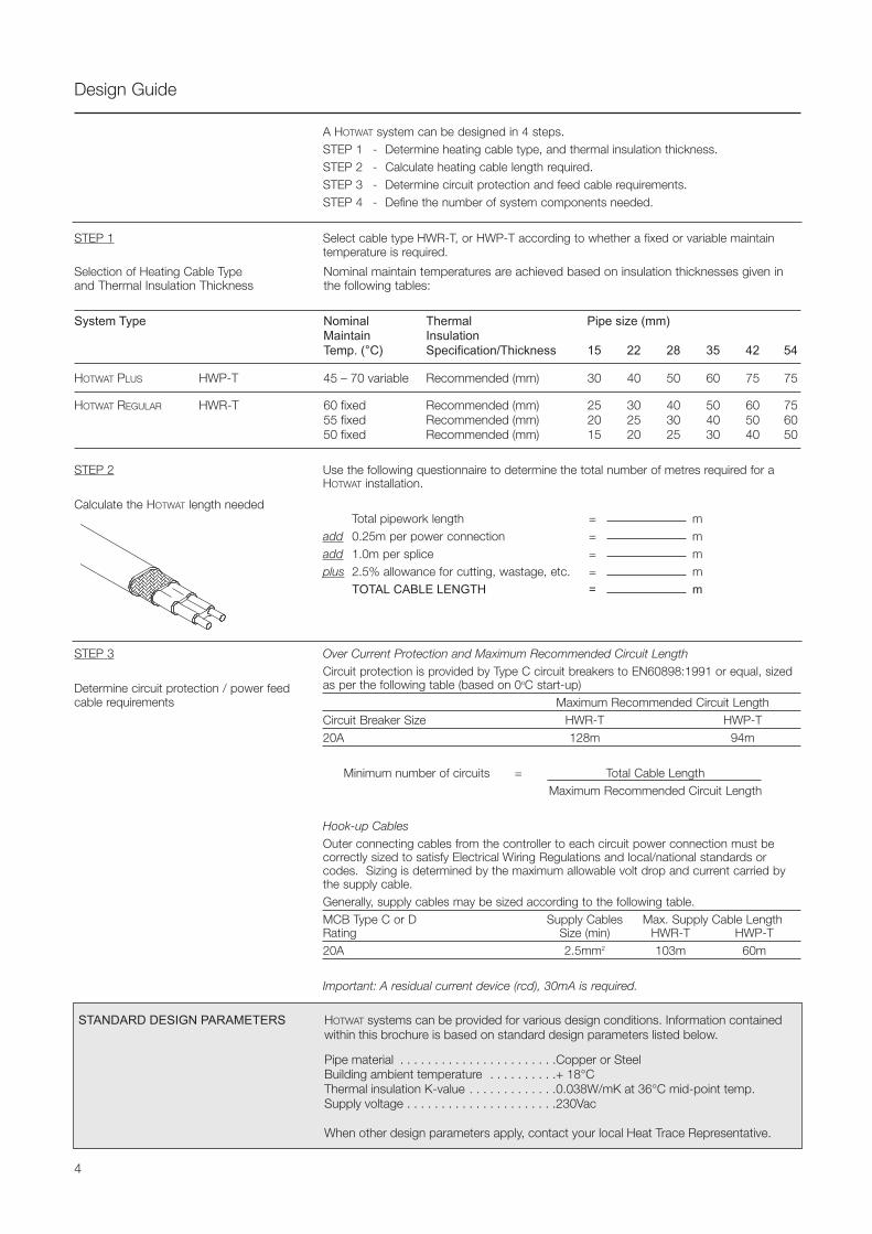
Design Guide
A HOTWAT system can be designed in 4 steps.STEP 1 - Determine heating cable type, and thermal insulation thickness.STEP 2 - Calculate heating cable length required.STEP 3 - Determine circuit protection and feed cable requirements.STEP 4 - Define the number of system components needed.
Select cable type HWR-T, or HWP-T according to whether a fixed or variable maintaintemperature is required.
STEP 1
Selection of Heating Cable Type Nominal maintain temperatures are achieved based on insulation thicknesses given in and Thermal Insulation Thickness the following tables:
System Type Nominal Thermal Pipe size (mm)Maintain InsulationTemp. (°C) Specification/Thickness 15 22 28 35 42 54
HOTWAT PLUS HWP-T 45 – 70 variable Recommended (mm) 30 40 50 60 75 75
HOTWAT REGULAR HWR-T 60 fixed Recommended (mm) 25 30 40 50 60 7555 fixed Recommended (mm) 20 25 30 40 50 6050 fixed Recommended (mm) 15 20 25 30 40 50
STEP 2
Calculate the HOTWAT length needed
Use the following questionnaire to determine the total number of metres required for aHOTWAT installation.
Total pipework length = madd 0.25m per power connection = madd 1.0m per splice = mplus 2.5% allowance for cutting, wastage, etc. = m
TOTAL CABLE LENGTH = m
STEP 3
Determine circuit protection / power feedcable requirements
Over Current Protection and Maximum Recommended Circuit LengthCircuit protection is provided by Type C circuit breakers to EN60898:1991 or equal, sizedas per the following table (based on 0oC start-up)
Maximum Recommended Circuit LengthCircuit Breaker Size HWR-T HWP-T20A 128m 94m
Minimum number of circuits = Total Cable LengthMaximum Recommended Circuit Length
Hook-up CablesOuter connecting cables from the controller to each circuit power connection must becorrectly sized to satisfy Electrical Wiring Regulations and local/national standards orcodes. Sizing is determined by the maximum allowable volt drop and current carried bythe supply cable.Generally, supply cables may be sized according to the following table.MCB Type C or D Supply Cables Max. Supply Cable LengthRating Size (min) HWR-T HWP-T20A 2.5mm2 103m 60m
Important: A residual current device (rcd), 30mA is required.
STANDARD DESIGN PARAMETERS HOTWAT systems can be provided for various design conditions. Information containedwithin this brochure is based on standard design parameters listed below.
Pipe material . . . . . . . . . . . . . . . . . . . . . . .Copper or SteelBuilding ambient temperature . . . . . . . . . .+ 18°CThermal insulation K-value . . . . . . . . . . . . .0.038W/mK at 36°C mid-point temp.Supply voltage . . . . . . . . . . . . . . . . . . . . . .230Vac
When other design parameters apply, contact your local Heat Trace Representative.
4
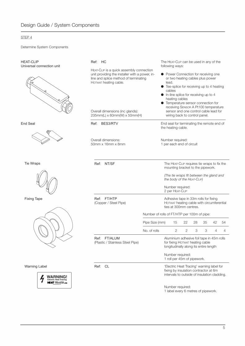
Design Guide / System Components
STEP 4
Determine System Components
HEAT-CLIPUniversal connection unit
End Seal
Ref: HC
HEAT-CLIP is a quick assembly connectionunit providing the installer with a power, in-line and splice method of terminatingHOTWAT heating cable.
Overall dimensions (inc glands):235mm(L) x 60mm(W) x 50mm(H)
Ref: BES3/RTV
Overall dimensions:50mm x 16mm x 8mm
The HEAT-CLIP can be used in any of thefollowing ways:
Power Connection for receiving oneor two heating cables plus powerlead.
Tee-splice for receiving up to 4 heatingcables
In-line splice for receiving up to 4heating cables
Temperature sensor connection forreceiving SENSOR A Pt100 temperaturesensor and one control cable lead forwiring back to control panel.
End seal for terminating the remote end ofthe heating cable.
Number required:1 per each end of circuit
The HEAT-CLIP requires tie wraps to fix themounting bracket to the pipework.
(The tie wraps fit between the gland andthe body of the HEAT-CLIP)
Number required:2 per HEAT-CLIP
Ref: NT/SFTie Wraps
Ref: FT/HTP(Copper / Steel Pipe)
Adhesive tape in 33m rolls for fixingHOTWAT heating cable with circumferentialties at 300mm centres.
Number of rolls of FT/HTP per 100m of pipe:
Pipe Size (mm) 15 22 28 35 42 54
No. of rolls 2 2 3 3 4 4
Fixing Tape
Ref: FT/ALUM(Plastic / Stainless Steel Pipe)
Aluminium adhesive foil tape in 45m rollsfor fixing HOTWAT heating cablelongitudinally along its entire length
Number required:1 roll per 45m of pipework.
‘Electric Heat Tracing’ warning label forfixing by insulation contractor at 6mintervals to outside of insulation cladding.
Number required:1 label every 6 metres of pipework.
Ref: CLWarning Label
5
WARNING! Electric Heat Tracing
www.heat-trace.com
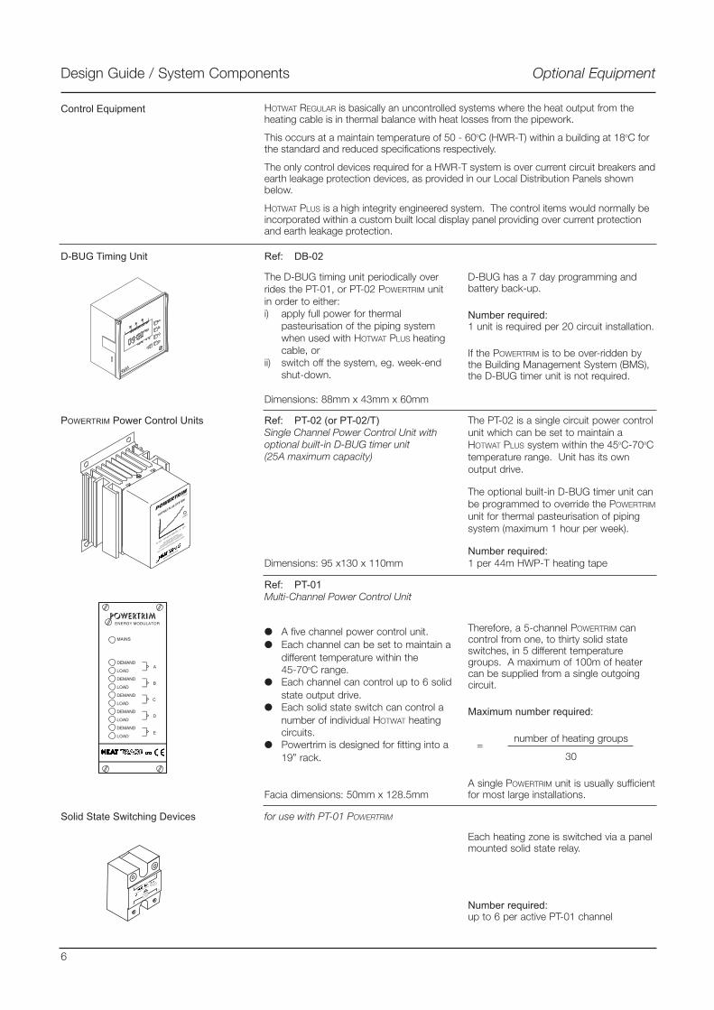
Design Guide / System Components Optional Equipment
Control Equipment HOTWAT REGULAR is basically an uncontrolled systems where the heat output from theheating cable is in thermal balance with heat losses from the pipework.
This occurs at a maintain temperature of 50 - 60oC (HWR-T) within a building at 18oC forthe standard and reduced specifications respectively.
The only control devices required for a HWR-T system is over current circuit breakers andearth leakage protection devices, as provided in our Local Distribution Panels shownbelow.
HOTWAT PLUS is a high integrity engineered system. The control items would normally beincorporated within a custom built local display panel providing over current protectionand earth leakage protection.
POWERTRIM
MAINS
DEMAND
LOAD
DEMAND
LOAD
DEMAND
LOAD
DEMAND
LOAD
DEMAND
LOAD
A
B
C
D
E
ENERGY MODULATOR
POWERTRIM Power Control Units
Ref: PT-01Multi-Channel Power Control Unit
A five channel power control unit. Each channel can be set to maintain a
different temperature within the45-70oC range.
Each channel can control up to 6 solidstate output drive.
Each solid state switch can control anumber of individual HOTWAT heatingcircuits.
Powertrim is designed for fitting into a19” rack.
Facia dimensions: 50mm x 128.5mm
Therefore, a 5-channel POWERTRIM cancontrol from one, to thirty solid stateswitches, in 5 different temperaturegroups. A maximum of 100m of heatercan be supplied from a single outgoingcircuit.
Maximum number required:
number of heating groups
30
A single POWERTRIM unit is usually sufficientfor most large installations.
=
The D-BUG timing unit periodically overrides the PT-01, or PT-02 POWERTRIM unitin order to either:i) apply full power for thermal
pasteurisation of the piping systemwhen used with HOTWAT PLUS heatingcable, or
ii) switch off the system, eg. week-endshut-down.
Dimensions: 88mm x 43mm x 60mm
D-BUG Timing Unit Ref: DB-02
D-BUG has a 7 day programming andbattery back-up.
Number required:1 unit is required per 20 circuit installation.
If the POWERTRIM is to be over-ridden bythe Building Management System (BMS),the D-BUG timer unit is not required.
Ref: PT-02 (or PT-02/T)Single Channel Power Control Unit withoptional built-in D-BUG timer unit(25A maximum capacity)
Dimensions: 95 x130 x 110mm
The PT-02 is a single circuit power controlunit which can be set to maintain aHOTWAT PLUS system within the 45oC-70oCtemperature range. Unit has its ownoutput drive.
The optional built-in D-BUG timer unit canbe programmed to override the POWERTRIM
unit for thermal pasteurisation of pipingsystem (maximum 1 hour per week).
Number required:1 per 44m HWP-T heating tape
Solid State Switching Devices for use with PT-01 POWERTRIM
Each heating zone is switched via a panelmounted solid state relay.
Number required:up to 6 per active PT-01 channel
6
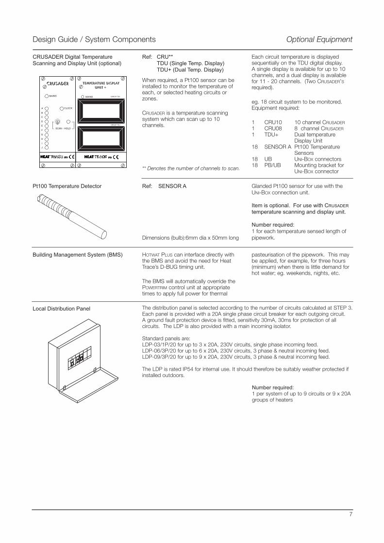
Design Guide / System Components Optional Equipment
Glanded Pt100 sensor for use with theUNI-BOX connection unit.
Item is optional. For use with CRUSADERtemperature scanning and display unit.
Number required:1 for each temperature sensed length ofpipework.
Ref: SENSOR A
Dimensions (bulb):6mm dia x 50mm long
Pt100 Temperature Detector
CRUSADER
MAINS
SCAN - HOLD
CLOCKA
B
C
D
E
F
G
H
I
J
TEMPERATURE DISPLAYUNIT +
MAINS GROUP TDU
GROUP TDU
The distribution panel is selected according to the number of circuits calculated at STEP 3.Each panel is provided with a 20A single phase circuit breaker for each outgoing circuit.A ground fault protection device is fitted, sensitivity 30mA, 30ms for protection of allcircuits. The LDP is also provided with a main incoming isolator.
Standard panels are:LDP-03/1P/20 for up to 3 x 20A, 230V circuits, single phase incoming feed.LDP-06/3P/20 for up to 6 x 20A, 230V circuits, 3 phase & neutral incoming feed.LDP-09/3P/20 for up to 9 x 20A, 230V circuits, 3 phase & neutral incoming feed.
The LDP is rated IP54 for internal use. It should therefore be suitably weather protected ifinstalled outdoors.
Number required:1 per system of up to 9 circuits or 9 x 20A groups of heaters
Local Distribution Panel
CRUSADER Digital TemperatureScanning and Display Unit (optional)
Ref: CRU**TDU (Single Temp. Display)TDU+ (Dual Temp. Display)
When required, a Pt100 sensor can beinstalled to monitor the temperature ofeach, or selected heating circuits orzones.
CRUSADER is a temperature scanningsystem which can scan up to 10channels.
** Denotes the number of channels to scan.
Each circuit temperature is displayedsequentially on the TDU digital display.A single display is available for up to 10channels, and a dual display is availablefor 11 - 20 channels. (Two CRUSADER’Srequired).
eg. 18 circuit system to be monitored.Equipment required:
1 CRU10 10 channel CRUSADER
1 CRU08 8 channel CRUSADER
1 TDU+ Dual temperature Display Unit
18 SENSOR A Pt100 Temperature Sensors
18 UB UNI-BOX connectors18 PB/UB Mounting bracket for
UNI-BOX connector
Building Management System (BMS) HOTWAT PLUS can interface directly withthe BMS and avoid the need for HeatTrace’s D-BUG timing unit.
The BMS will automatically override thePOWERTRIM control unit at appropriatetimes to apply full power for thermal
pasteurisation of the pipework. This maybe applied, for example, for three hours(minimum) when there is little demand forhot water; eg. weekends, nights, etc.
7
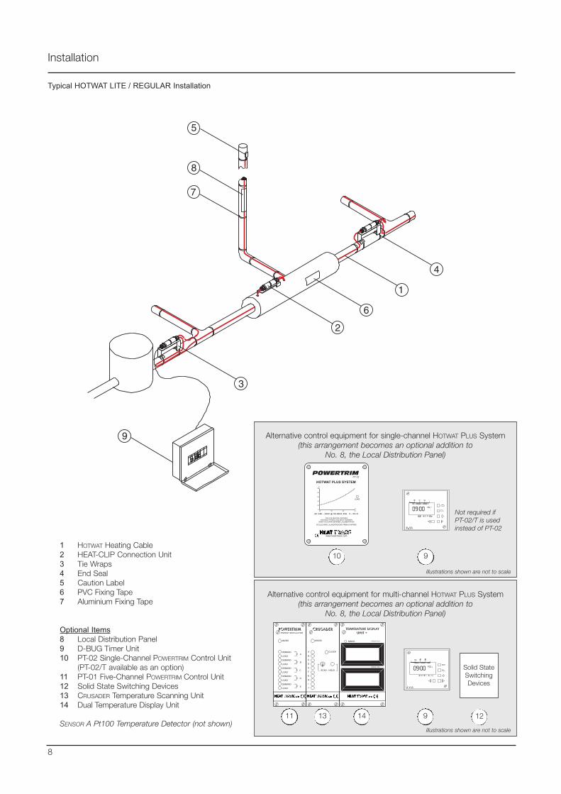
Alternative control equipment for multi-channel HOTWAT PLUS System(this arrangement becomes an optional addition to
No. 8, the Local Distribution Panel)
Typical HOTWAT LITE / REGULAR Installation
Installation
POWERTRIM
MAINS
DEMAND
LOAD
DEMAND
LOAD
DEMAND
LOAD
DEMAND
LOAD
DEMAND
LOAD
A
B
C
D
E
ENERGY MODULATOR
CRUSADER
MAINS
SCAN - HOLD
CLOCKA
B
C
D
E
F
G
H
I
J
TEMPERATURE DISPLAYUNIT +
MAINS GROUP TDU
GROUP TDU
1 HOTWAT Heating Cable2 HEAT-CLIP Connection Unit3 Tie Wraps4 End Seal5 Caution Label6 PVC Fixing Tape7 Aluminium Fixing Tape
Optional Items8 Local Distribution Panel9 D-BUG Timer Unit10 PT-02 Single-Channel POWERTRIM Control Unit
(PT-02/T available as an option)11 PT-01 Five-Channel POWERTRIM Control Unit12 Solid State Switching Devices13 CRUSADER Temperature Scanning Unit14 Dual Temperature Display Unit
SENSOR A Pt100 Temperature Detector (not shown)11 13 14 9
Alternative control equipment for single-channel HOTWAT PLUS System(this arrangement becomes an optional addition to
No. 8, the Local Distribution Panel)
POWERTRIMPT 02
HOTWAT PLUS SYSTEM
AC 220 - 240V @ 50-60Hz 25A 0 - 65∞C
ISOLATE BEFORE OPENINGVOR DEM ÷FFNEN VOM NETZ TRENNEN
AVANT D'OUVRIR SEPARER L'ALIMENTATION
SCOLLEGARE L'ALIMENTAZIONE PRIMA DI APRIRE
www.heat-trace.com
LOAD
0
20
40
60
80
100
40 50 60 70∞C
%
10 9
12
illustrations shown are not to scale
illustrations shown are not to scale
8
Solid StateSwitchingDevices
Not required ifPT-02/T is usedinstead of PT-02
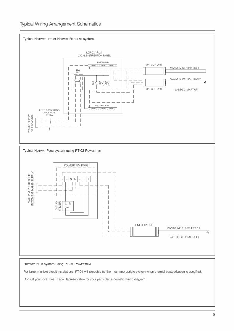
Typical Wiring Arrangement Schematics
9
Typical HOTWAT LITE or HOTWAT REGULAR system
UNI-CLIP UNIT
63A RCD
LDP-03/1P/20 LOCAL DISTRIBUTION PANEL
20A
20A
20A
NEUTRAL BAR
INTER-CONNECTING CABLE RATED
AT 63A
EARTH BAR
230V
AC
SU
PP
LY
FULL
LO
AD
63A
MAXIMUM OF 135m HWR-T
UNI-CLIP UNIT
MAXIMUM OF 135m HWR-T
(+20 DEG C START-UP)
Typical HOTWAT PLUS system using PT-02 POWERTRIM
POWERTRIM PT-02
E L N
L N
N L T T
UNI-CLIP UNITMAXIMUM OF 65m HWP-T
(+20 DEG C START-UP)
D-B
UG
(T
IME
R)MA
X. 2
5A P
RO
TEC
TED
IN
CO
MIN
G M
AIN
S S
UP
PLY
HOTWAT PLUS system using PT-01 POWERTRIM
For large, multiple circuit installations, PT-01 will probably be the most appropriate system when thermal pasteurisation is specified.
Consult your local Heat Trace Representative for your particular schematic wiring diagram
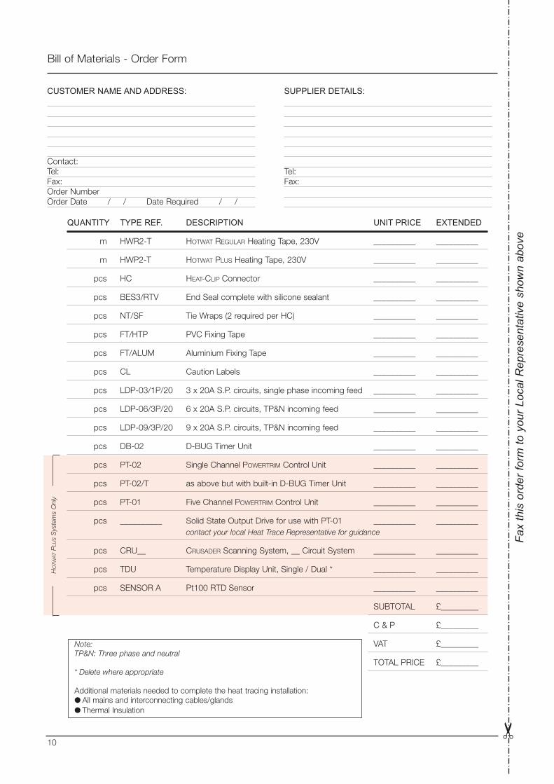
Bill of Materials - Order Form
Fa
x th
is o
rder
form
to y
our L
ocal
Rep
rese
ntat
ive
show
n ab
ove
QUANTITY TYPE REF. DESCRIPTION UNIT PRICE EXTENDED
m HWR2-T HOTWAT REGULAR Heating Tape, 230V __________ __________
m HWP2-T HOTWAT PLUS Heating Tape, 230V __________ __________
pcs HC HEAT-CLIP Connector __________ __________
pcs BES3/RTV End Seal complete with silicone sealant __________ __________
pcs NT/SF Tie Wraps (2 required per HC) __________ __________
pcs FT/HTP PVC Fixing Tape __________ __________
pcs FT/ALUM Aluminium Fixing Tape __________ __________
pcs CL Caution Labels __________ __________
pcs LDP-03/1P/20 3 x 20A S.P. circuits, single phase incoming feed __________ __________
pcs LDP-06/3P/20 6 x 20A S.P. circuits, TP&N incoming feed __________ __________
pcs LDP-09/3P/20 9 x 20A S.P. circuits, TP&N incoming feed __________ __________
pcs DB-02 D-BUG Timer Unit __________ __________
pcs PT-02 Single Channel POWERTRIM Control Unit __________ __________
pcs PT-02/T as above but with built-in D-BUG Timer Unit __________ __________
pcs PT-01 Five Channel POWERTRIM Control Unit __________ __________
pcs __________ Solid State Output Drive for use with PT-01 __________ __________contact your local Heat Trace Representative for guidance
pcs CRU__ CRUSADER Scanning System, __ Circuit System __________ __________
pcs TDU Temperature Display Unit, Single / Dual * __________ __________
pcs SENSOR A Pt100 RTD Sensor __________ __________
SUBTOTAL £_________
C & P £_________
VAT £_________
TOTAL PRICE £_________
CUSTOMER NAME AND ADDRESS:
Contact:Tel:Fax:Order NumberOrder Date / / Date Required / /
SUPPLIER DETAILS:
Tel:Fax:
HO
TWAT
PLU
SS
yste
ms
Onl
y
10
Note:TP&N: Three phase and neutral
* Delete where appropriate
Additional materials needed to complete the heat tracing installation: All mains and interconnecting cables/glands Thermal Insulation

Pipework Layout
PD
G01
0 08
/03
DR
AFT
Tracer House, Cromwell Road, Bredbury, Stockport, Cheshire, SK6 2RF, U.K.Tel: +44(0)161-430 8333 Fax: +44(0)161-430 8654 http://www.heat-trace.com
The information given herein, including drawings, illustrations and schematics (which are intended for illustration purposes only), is believed to be reliable. However, Heat Trace Ltd makes nowarranties as to its accuracy or completeness and disclaims any liability in connection with its use. Users of Heat Trace Ltd products should make their own evaluation to determine the suitabilityof each such product for specific applications. In no way will Heat Trace Ltd be liable for any damages arising out of the misuse, resale or use of the product.
Presented by:
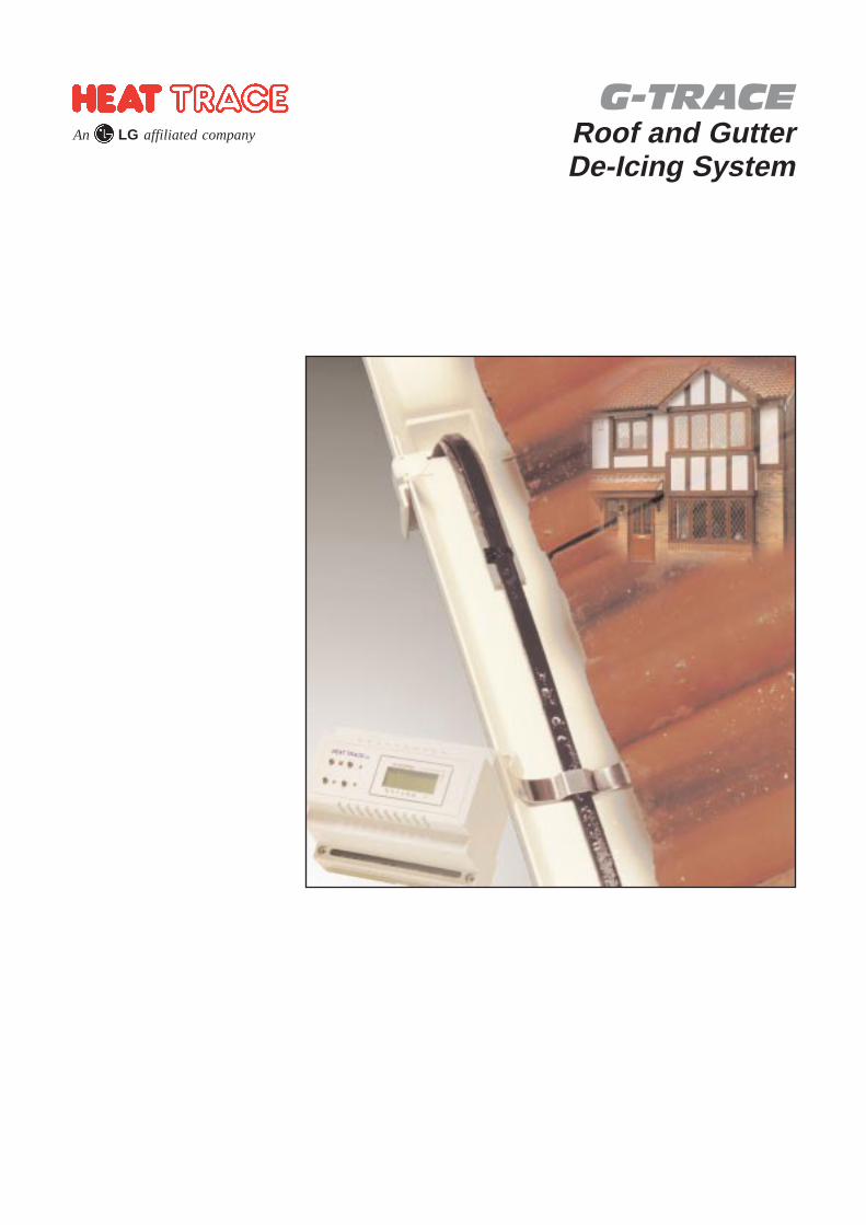
G-TRACERoof and GutterDe-Icing System
An LG affiliated company
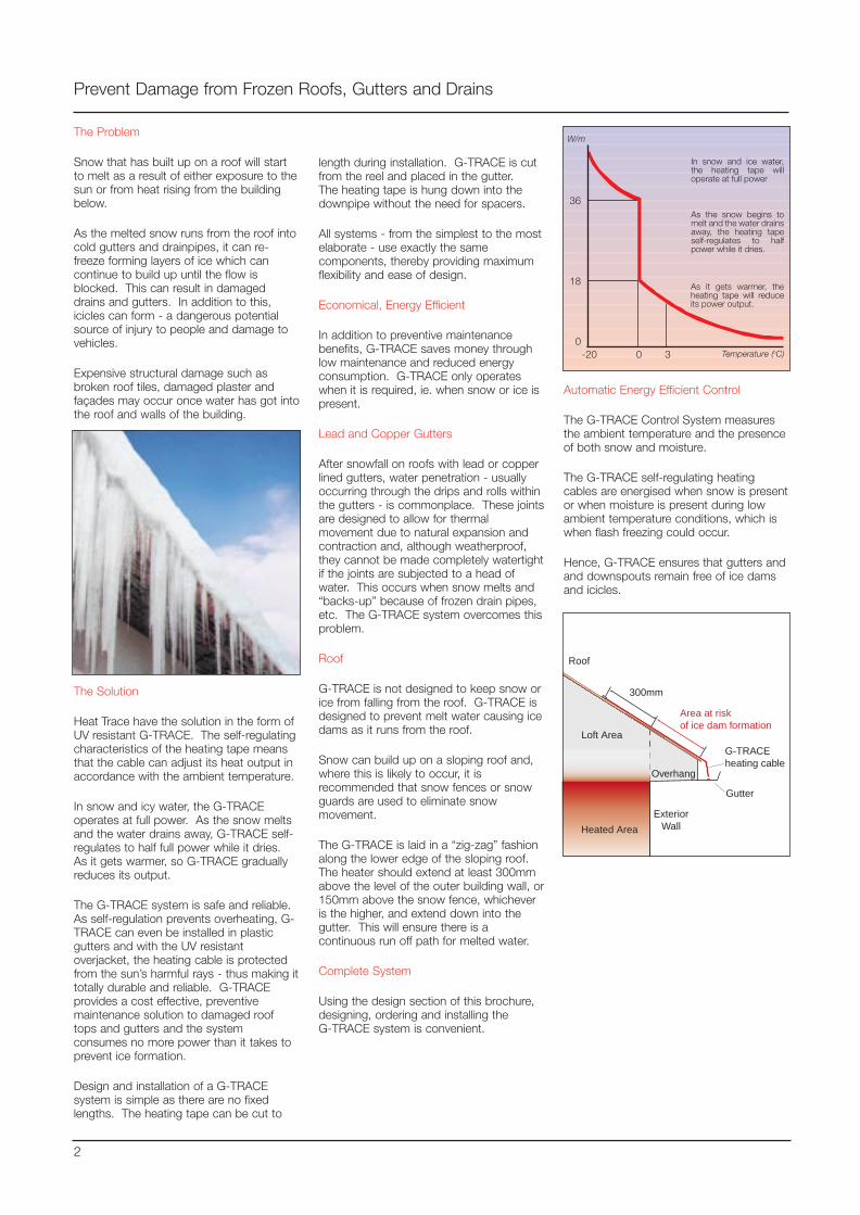
The Problem
Snow that has built up on a roof will startto melt as a result of either exposure to thesun or from heat rising from the buildingbelow.
As the melted snow runs from the roof intocold gutters and drainpipes, it can re-freeze forming layers of ice which cancontinue to build up until the flow isblocked. This can result in damageddrains and gutters. In addition to this,icicles can form - a dangerous potentialsource of injury to people and damage tovehicles.
Expensive structural damage such asbroken roof tiles, damaged plaster andfaçades may occur once water has got intothe roof and walls of the building.
The Solution
Heat Trace have the solution in the form ofUV resistant G-TRACE. The self-regulatingcharacteristics of the heating tape meansthat the cable can adjust its heat output inaccordance with the ambient temperature.
In snow and icy water, the G-TRACEoperates at full power. As the snow meltsand the water drains away, G-TRACE self-regulates to half full power while it dries.As it gets warmer, so G-TRACE graduallyreduces its output.
The G-TRACE system is safe and reliable.As self-regulation prevents overheating, G-TRACE can even be installed in plasticgutters and with the UV resistantoverjacket, the heating cable is protectedfrom the sun’s harmful rays - thus making ittotally durable and reliable. G-TRACEprovides a cost effective, preventivemaintenance solution to damaged rooftops and gutters and the systemconsumes no more power than it takes toprevent ice formation.
Design and installation of a G-TRACEsystem is simple as there are no fixedlengths. The heating tape can be cut to
Prevent Damage from Frozen Roofs, Gutters and Drains
length during installation. G-TRACE is cutfrom the reel and placed in the gutter.The heating tape is hung down into thedownpipe without the need for spacers.
All systems - from the simplest to the mostelaborate - use exactly the samecomponents, thereby providing maximumflexibility and ease of design.
Economical, Energy Efficient
In addition to preventive maintenancebenefits, G-TRACE saves money throughlow maintenance and reduced energyconsumption. G-TRACE only operateswhen it is required, ie. when snow or ice ispresent.
Lead and Copper Gutters
After snowfall on roofs with lead or copperlined gutters, water penetration - usuallyoccurring through the drips and rolls withinthe gutters - is commonplace. These jointsare designed to allow for thermalmovement due to natural expansion andcontraction and, although weatherproof,they cannot be made completely watertightif the joints are subjected to a head ofwater. This occurs when snow melts and“backs-up” because of frozen drain pipes,etc. The G-TRACE system overcomes thisproblem.
Roof
G-TRACE is not designed to keep snow orice from falling from the roof. G-TRACE isdesigned to prevent melt water causing icedams as it runs from the roof.
Snow can build up on a sloping roof and,where this is likely to occur, it isrecommended that snow fences or snowguards are used to eliminate snowmovement.
The G-TRACE is laid in a “zig-zag” fashionalong the lower edge of the sloping roof.The heater should extend at least 300mmabove the level of the outer building wall, or150mm above the snow fence, whicheveris the higher, and extend down into thegutter. This will ensure there is acontinuous run off path for melted water.
Complete System
Using the design section of this brochure,designing, ordering and installing the G-TRACE system is convenient.
As it gets warmer, theheating tape will reduceits power output.
In snow and ice water,the heating tape willoperate at full power
As the snow begins tomelt and the water drainsaway, the heating tapeself-regulates to halfpower while it dries.
36
18
0-20 0 3 Temperature (oC)
W/m
Automatic Energy Efficient Control
The G-TRACE Control System measuresthe ambient temperature and the presenceof both snow and moisture.
The G-TRACE self-regulating heatingcables are energised when snow is presentor when moisture is present during lowambient temperature conditions, which iswhen flash freezing could occur.
Hence, G-TRACE ensures that gutters andand downspouts remain free of ice damsand icicles.
Heated Area
Gutter
Loft Area
Overhang
ExteriorWall
G-TRACEheating cable
Roof
300mm
Area at riskof ice dam formation
2
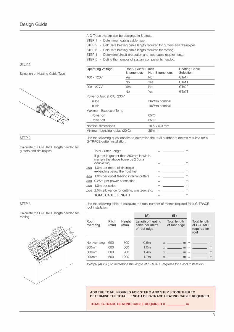
A G-Trace system can be designed in 5 steps.STEP 1 - Determine heating cable type.STEP 2 - Calculate heating cable length required for gutters and drainpipes.STEP 3 - Calculate heating cable length required for roofing.STEP 4 - Determine circuit protection and feed cable requirements.STEP 5 - Define the number of system components needed.
Operating Voltage Roof / Gutter Finish Heating CableBitumenous Non-Bitumenous Selection
100 - 120V Yes No GTe1FNo Yes GTe1T
208 - 277V Yes No GTe2FNo Yes GTe2T
Power output at 0oC, 230VIn Ice 36W/m nominalIn Air 18W/m nominal
Maximum Exposure TempPower on 65oCPower off 85oC
Nominal dimensions 10.5 x 5.9 mmMinimum bending radius (20oC) 35mm
Design Guide
STEP 1
Selection of Heating Cable Type
STEP 2
Calculate the G-TRACE length needed forgutters and drainpipes
Use the following questionnaire to determine the total number of metres required for a G-TRACE gutter installation.
Total Gutter Length = mIf gutter is greater than 300mm in width,multiply the above figure by 2 (for adouble run) = m
add 1.0m per metre of drainpipe (extending below the frost line) = m
add 1.0m per outlet feeding internal gutters = madd 0.25m per power connection = madd 1.0m per splice = mplus 2.5% allowance for cutting, wastage, etc. = m
TOTAL CABLE LENGTH = m
STEP 3
Calculate the G-TRACE length needed forroofing
Use the following table to calculate the total number of metres required for a G-TRACEroof installation.
(A) (B)
Roof Pitch Height Length of heating Total length Total lengthoverhang (mm) (mm) cable per metre of roof edge of G-TRACE
of roof edge required forroof
No overhang 600 300 0.6m x m = m300mm 600 600 1.0m x m = m600mm 600 900 1.4m x m = m900mm 600 1200 1.7m x m = m
Multiply (A) x (B) to determine the length of G-TRACE required for a roof installation.
ADD THE TOTAL FIGURES FOR STEP 2 AND STEP 3 TOGETHER TODETERMINE THE TOTAL LENGTH OF G-TRACE HEATING CABLE REQUIRED.
TOTAL G-TRACE HEATING CABLE REQUIRED = m
3
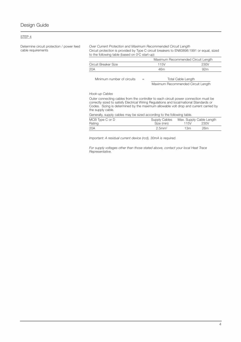
STEP 4
Determine circuit protection / power feedcable requirements
Over Current Protection and Maximum Recommended Circuit LengthCircuit protection is provided by Type C circuit breakers to EN60898:1991 or equal, sizedto the following table (based on 0oC start-up)
Maximum Recommended Circuit LengthCircuit Breaker Size 115V 230V20A 46m 92m
Minimum number of circuits = Total Cable LengthMaximum Recommended Circuit Length
Hook-up CablesOuter connecting cables from the controller to each circuit power connection must becorrectly sized to satisfy Electrical Wiring Regulations and local/national Standards orCodes. Sizing is determined by the maximum allowable volt drop and current carried bythe supply cable.Generally, supply cables may be sized according to the following table.MCB Type C or D Supply Cables Max. Supply Cable LengthRating Size (min) 115V 230V20A 2.5mm2 13m 26m
Important: A residual current device (rcd), 30mA is required.
For supply voltages other than those stated above, contact your local Heat TraceRepresentative.
Design Guide
4
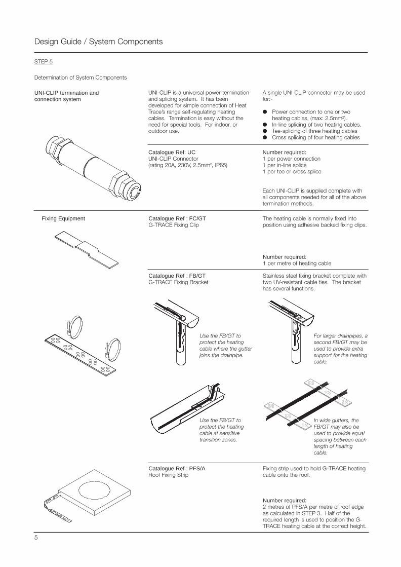
UNI-CLIP termination andconnection system
UNI-CLIP is a universal power terminationand splicing system. It has beendeveloped for simple connection of HeatTrace’s range self-regulating heatingcables. Termination is easy without theneed for special tools. For indoor, oroutdoor use.
A single UNI-CLIP connector may be usedfor:-
Power connection to one or twoheating cables, (max: 2.5mm²).
In-line splicing of two heating cables, Tee-splicing of three heating cables Cross splicing of four heating cables
Catalogue Ref: UCUNI-CLIP Connector(rating 20A, 230V, 2.5mm2, IP65)
Catalogue Ref : FC/GTG-TRACE Fixing Clip
Number required:1 per power connection1 per in-line splice1 per tee or cross splice
Each UNI-CLIP is supplied complete withall components needed for all of the abovetermination methods.
The heating cable is normally fixed intoposition using adhesive backed fixing clips.
Number required:1 per metre of heating cable
Design Guide / System Components
STEP 5
Determination of System Components
Catalogue Ref : FB/GTG-TRACE Fixing Bracket
Stainless steel fixing bracket complete withtwo UV-resistant cable ties. The brackethas several functions.
Use the FB/GT toprotect the heatingcable where the gutterjoins the drainpipe.
For larger drainpipes, asecond FB/GT may beused to provide extrasupport for the heatingcable.
Use the FB/GT toprotect the heatingcable at sensitivetransition zones.
In wide gutters, theFB/GT may also beused to provide equalspacing between eachlength of heatingcable.
Fixing Equipment
Catalogue Ref : PFS/ARoof Fixing Strip
Fixing strip used to hold G-TRACE heatingcable onto the roof.
Number required:2 metres of PFS/A per metre of roof edgeas calculated in STEP 3. Half of therequired length is used to position the G-TRACE heating cable at the correct height.
5
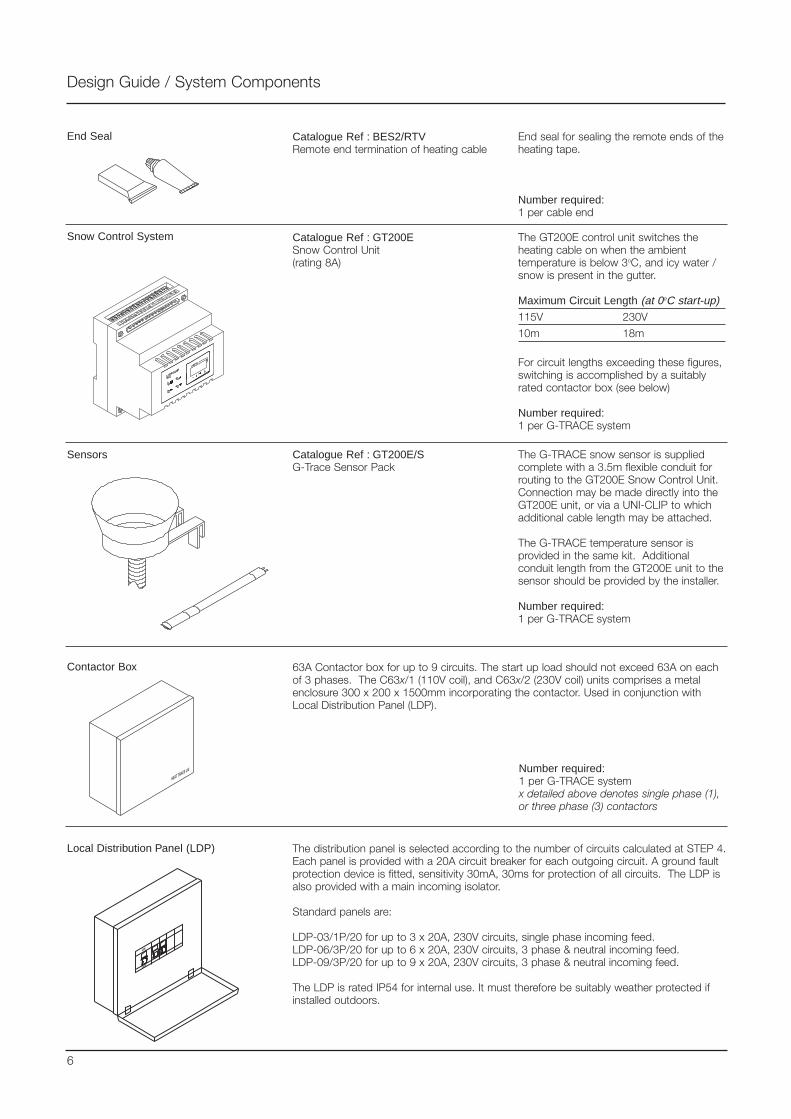
Design Guide / System Components
Catalogue Ref : BES2/RTVRemote end termination of heating cable
End seal for sealing the remote ends of theheating tape.
Number required:1 per cable end
Catalogue Ref : GT200ESnow Control Unit(rating 8A)
The GT200E control unit switches theheating cable on when the ambienttemperature is below 3oC, and icy water /snow is present in the gutter.
Maximum Circuit Length (at 0oC start-up)
115V 230V
10m 18m
For circuit lengths exceeding these figures,switching is accomplished by a suitablyrated contactor box (see below)
Number required:1 per G-TRACE system
The distribution panel is selected according to the number of circuits calculated at STEP 4.Each panel is provided with a 20A circuit breaker for each outgoing circuit. A ground faultprotection device is fitted, sensitivity 30mA, 30ms for protection of all circuits. The LDP isalso provided with a main incoming isolator.
Standard panels are:
LDP-03/1P/20 for up to 3 x 20A, 230V circuits, single phase incoming feed.LDP-06/3P/20 for up to 6 x 20A, 230V circuits, 3 phase & neutral incoming feed.LDP-09/3P/20 for up to 9 x 20A, 230V circuits, 3 phase & neutral incoming feed.
The LDP is rated IP54 for internal use. It must therefore be suitably weather protected ifinstalled outdoors.
63A Contactor box for up to 9 circuits. The start up load should not exceed 63A on eachof 3 phases. The C63x/1 (110V coil), and C63x/2 (230V coil) units comprises a metalenclosure 300 x 200 x 1500mm incorporating the contactor. Used in conjunction withLocal Distribution Panel (LDP).
Number required:1 per G-TRACE systemx detailed above denotes single phase (1), or three phase (3) contactors
End Seal
Snow Control System
Contactor Box
Local Distribution Panel (LDP)
Sensors Catalogue Ref : GT200E/SG-Trace Sensor Pack
The G-TRACE snow sensor is suppliedcomplete with a 3.5m flexible conduit forrouting to the GT200E Snow Control Unit.Connection may be made directly into theGT200E unit, or via a UNI-CLIP to whichadditional cable length may be attached.
The G-TRACE temperature sensor isprovided in the same kit. Additionalconduit length from the GT200E unit to thesensor should be provided by the installer.
Number required:1 per G-TRACE system
6
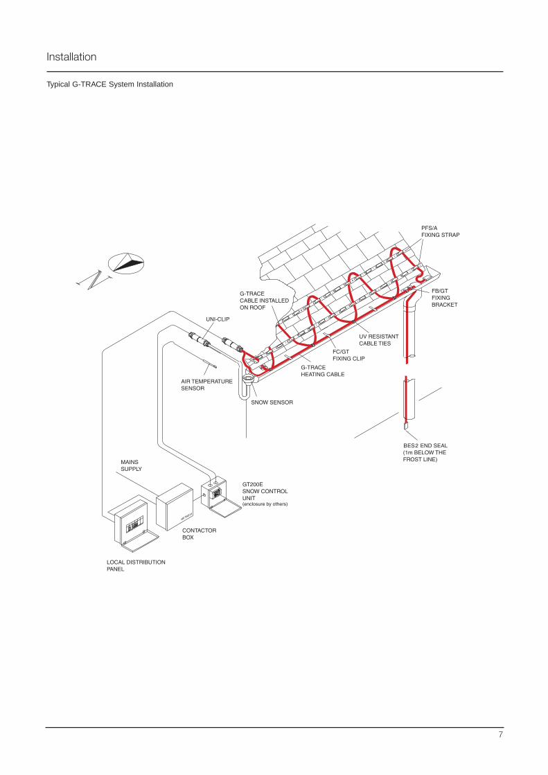
Typical G-TRACE System Installation
Installation
7
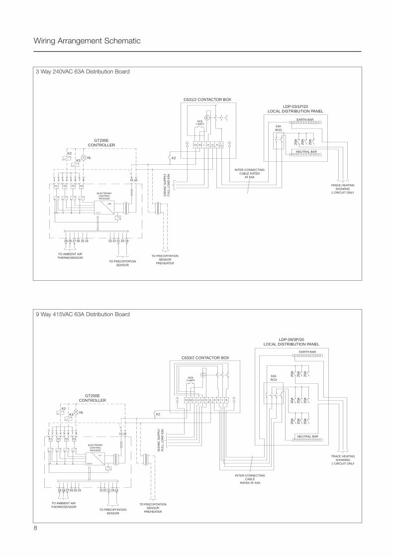
Wiring Arrangement Schematic
63ARCD
MCB2 AMPS
S1
1
K1 K2 K3 K4
15 162 3 4 5 6 7 8
29 28 27 26 25 24 23 22 21 20 19
S2 L N N N LOUT
C
K2K2
K3HL
230V
AC
SU
PP
LYF
ULL
LO
AD
63A
C631/2 CONTACTOR BOX
LDP-03/1P/20LOCAL DISTRIBUTION PANEL
20A
20A
20A
NEUTRAL BAR
TRACE HEATINGSHOWING
1 CIRCUIT ONLY
INTER-CONNECTINGCABLE RATED
AT 63A
GT200ECONTROLLER
ELECTRONICCONTROLPACKAGE
TO AMBIENT AIRTHERMOSENSOR
TO PRECIPITATIONSENSOR
TO PRECIPITATIONSENSOR
PREHEATER
EARTH BAR
C633/2 CONTACTOR BOX
TO PRECIPITATIONSENSOR
PREHEATERTO PRECIPITATION
SENSOR
TO AMBIENT AIRTHERMOSENSOR
GT200ECONTROLLER
ELECTRONICCONTROLPACKAGE
K1 K2 K3 K4
1 2 3 4 5 6 7 8
K2
K2K3HL
29 28 27 26 25 24 23 22 21 20 19
15 16
415V
AC
SU
PP
LYF
ULL
LO
AD
63A
INTER-CONNECTINGCABLE
RATED AT 63A
TRACE HEATINGSHOWING
1 CIRCUIT ONLY
63ARCD
NEUTRAL BAR
EARTH BAR
20A
20A
20A
20A
20A
20A
20A
20A
20A
MCB2 AMPS
S1 S2 L1 L2 L3 N N N R Y B
C
LDP-09/3P/20LOCAL DISTRIBUTION PANEL
3 Way 240VAC 63A Distribution Board
9 Way 415VAC 63A Distribution Board
8
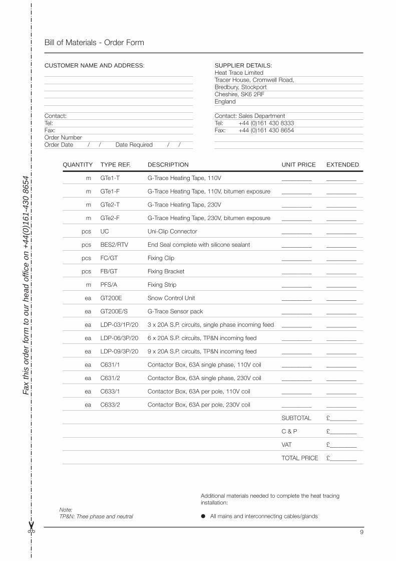
Bill of Materials - Order Form
Fax
this
ord
er fo
rm to
our
hea
d of
fice
on +
44(0
)161
-430
865
4
Additional materials needed to complete the heat tracinginstallation:
All mains and interconnecting cables/glands
QUANTITY TYPE REF. DESCRIPTION UNIT PRICE EXTENDED
m GTe1-T G-Trace Heating Tape, 110V __________ __________
m GTe1-F G-Trace Heating Tape, 110V, bitumen exposure __________ __________
m GTe2-T G-Trace Heating Tape, 230V __________ __________
m GTe2-F G-Trace Heating Tape, 230V, bitumen exposure __________ __________
pcs UC Uni-Clip Connector __________ __________
pcs BES2/RTV End Seal complete with silicone sealant __________ __________
pcs FC/GT Fixing Clip __________ __________
pcs FB/GT Fixing Bracket __________ __________
m PFS/A Fixing Strip __________ __________
ea GT200E Snow Control Unit __________ __________
ea GT200E/S G-Trace Sensor pack __________ __________
ea LDP-03/1P/20 3 x 20A S.P. circuits, single phase incoming feed __________ __________
ea LDP-06/3P/20 6 x 20A S.P. circuits, TP&N incoming feed __________ __________
ea LDP-09/3P/20 9 x 20A S.P. circuits, TP&N incoming feed __________ __________
ea C631/1 Contactor Box, 63A single phase, 110V coil __________ __________
ea C631/2 Contactor Box, 63A single phase, 230V coil __________ __________
ea C633/1 Contactor Box, 63A per pole, 110V coil __________ __________
ea C633/2 Contactor Box, 63A per pole, 230V coil __________ __________
SUBTOTAL £_________
C & P £_________
VAT £_________
TOTAL PRICE £_________
CUSTOMER NAME AND ADDRESS:
Contact:Tel:Fax:Order NumberOrder Date / / Date Required / /
SUPPLIER DETAILS:Heat Trace LimitedTracer House, Cromwell Road,Bredbury, StockportCheshire, SK6 2RFEngland
Contact: Sales DepartmentTel: +44 (0)161 430 8333Fax: +44 (0)161 430 8654
9
Note:TP&N: Thee phase and neutral

Tracer House, Cromwell Road, Bredbury, Stockport, Cheshire, SK6 2RF, U.K.Tel: +44(0)161-430 8333 Fax: +44(0)161-430 8654 http://www.heat-trace.com
The information given herein, including drawings, illustrations and schematics (which are intended for illustration purposes only), is believed to be reliable. However, Heat Trace Ltd makes nowarranties as to its accuracy or completeness and disclaims any liability in connection with its use. Users of Heat Trace Ltd products should make their own evaluation to determine the suitabilityof each such product for specific applications. In no way will Heat Trace Ltd be liable for any damages arising out of the misuse, resale or use of the product.
PD
G02
0 03
/00
Presented by:
BS EN ISO 9001 Certificate No. 0160
FFLLOOOORRWWAARRMMSelf-Regulating Electric
Underfloor Heating SystemAn LG affiliated company
Comfort Heating
New and Retrofit Applications
Concrete and Timber Floors

The Applications
Floor warming is generally provided assupplementary heating to an existing heatsource in order to keep floor surfaces at acomfortable temperature.
FLOORWARM is suitable for domestic,commercial and industrial buildings. It maybe incorporated into new buildings andextensions, or retro-fitted to existing floors.FLOORWARM can be safely used withwooden and concrete floors
How it Works
FLOORWARM self-regulating heating cable isinstalled beneath the floor, often embeddedin the concrete, or in a screed, although itcan also be safely used with woodenfloors.
The principle of FLOORWARM, when usedwith a concrete floor, is to utilise the highthermal capacity of the floor slab as a heatreservoir which stores and emits heat on acontinuous basis.
When initially energised the heater works toits maximum output, reducing as the slabtemperature rises, until the requiredoptimum heat output is achieved.
By installing a self-regulating heating cable,that varies its output relative to the floortemperature, it is possible to achieve aneven heat distribution without localisedoverheating.
Electric Self-Regulating Underfloor Heating System
Floor Warming Principles
A comfortable room temperature largelydepends on the mean effectivetemperature, which is a function of theambient air temperature and the averageradiant surface temperature. Where largewarm surfaces such as the floor exist, it ispossible to achieve comfortable conditionswith a cooler air temperature. This resultsin a "fresher" environment and will meanreduced heat losses from the building withsubsequent savings in energy costs.
It is more comfortable and far safer to havean evenly distributed lower temperature ofbetween 20 - 30°C, than it is to have asingle high temperature heat source ofaround 100°C, or more, in one area of theroom, distributing heat by radiation andconvection. It is also more efficient andsafer to generate heat at the required floortemperature, rather than to generateexcessive temperatures and allowdistribution to reduce the temperature tothe required comfort level.
Ideal living room temperature gradients areconsidered to be about 24°C at floor leveland around 18-20°C at head level.FLOORWARM allows the latent heat stored inthe floor to be released in such a way as toachieve these conditions more effectively.The self-regulating characteristic ofFLOORWARM ensures that, as the roomreaches the desired temperature, thecapability of the floor to emit heatdiminishes. Furthermore, lying on the floorwill not result in over heating - making itperfectly safe for children and pets.
Efficiency
For greater efficiency, heat input to the floormay be provided via off peak, low tariffelectricity if, and when, it is available.Additional thermostat and timer controlsmay also be utilised for additional energysavings. An insulated floor isrecommended where possible.
Flexibility
FLOORWARM’S self-regulating capability alsoensures that the system responds tolocalised additional heat losses that mayoccur at open windows, doors, etc., byautomatically increasing the heat outputfrom the floor in that area. This self-regulating capability also ensures that thefloor cannot overheat, thus protectingagainst discomfort and inefficient use ofenergy.
The installed heating load determines theability of the system to achieve the requiredfloor operating temperature.
Bathroom Floors
Conservatory Floor
Room heating using traditional methods
Room heating using FLOORWARM system
The heat output from FLOORWARM issufficiently low to enable the heater to beused with a waterproof membrane in floorssubject to moisture, for example inbathrooms, shower rooms, etc.
Other Uses
In addition to domestic applications suchas conservatories, bathrooms, living rooms,bedrooms, loft areas, etc., FLOORWARM
offers equal benefits for commercialpremises such as offices, atria, receptionareas, rest rooms, etc.
Traditional Heating vs. FLOORWARM
With traditional central heating, the airimmediately around the radiator is heatedand, as the warm air rises, the heat isconcentrated high in the room whilst thefloor area remains colder.
FLOORWARM, however, radiates heatupwards from the floor - resulting in amuch more comfortable and even heatdistribution throughout the whole room.
2
“Self-regulating heaters cannot overheat or burn out”
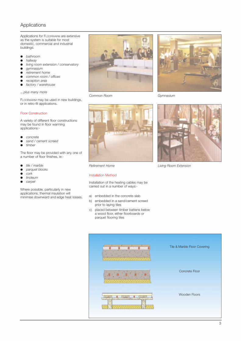
Applications
Applications for FLOORWARM are extensiveas the system is suitable for mostdomestic, commercial and industrialbuildings.
bathroom hallway living room extension / conservatory gymnasium retirement home common room / offices reception area factory / warehouse
...... plus many more
FLOORWARM may be used in new buildings,or in retro-fit applications.
Floor Construction
A variety of different floor constructionsmay be found in floor warmingapplications:-
concrete sand / cement screed timber
The floor may be provided with any one ofa number of floor finishes, ie:-
tile / marble parquet blocks cork linoleum carpet
Where possible, particularly in newapplications, thermal insulation willminimise downward and edge heat losses.
Common Room Gymnasium
Retirement Home Living Room Extension
Tile & Marble Floor Covering
Concrete Floor
Wooden Floors
3
Installation Method
Installation of the heating cables may becarried out in a number of ways:-
a) embedded in the concrete slab
b) embedded in a sand/cement screedprior to laying tiles
c) placed between timber battens belowa wood floor, either floorboards orparquet flooring tiles
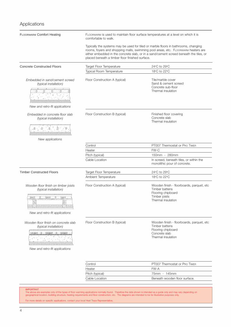
Applications
FLOORWARM Comfort Heating
Target Floor Temperature 24oC to 29oC
Typical Room Temperature 18oC to 22oC
Floor Construction A (typical) Tile/marble coverSand & cement screedConcrete sub-floorThermal insulation
Floor Construction B (typical) Finished floor coveringConcrete slabThermal insulation
Control PT007 Thermostat or PRO TIMER
Heater FW-C
Pitch (typical) 150mm - 280mm
Cable Location In screed, beneath tiles, or within themonolithic pour of concrete.
Embedded in sand/cement screed(typical installation)
Embedded in concrete floor slab(typical installation)
Wooden floor finish on timber joists(typical installation)
Target Floor Temperature 24oC to 29oC
Ambient Temperature 18oC to 22oC
Floor Construction A (typical) Wooden finish - floorboards, parquet, etcTimber battensFlooring chipboardTimber joistsThermal insulation
Floor Construction B (typical) Wooden finish - floorboards, parquet, etcTimber battensFlooring chipboardConcrete slabThermal insulation
Control PT007 Thermostat or PRO TIMER
Heater FW-A
Pitch (typical) 75mm - 145mm
Cable Location Beneath wooden floor surface.
Wooden floor finish on concrete slab(typical installation)
New and retro-fit applications
New and retro-fit applications
New applications
4
IMPORTANTThe above are examples only of the types of floor warming applications normally found. Therefore the data shown is intended as a guide only and may vary depending ongeographical location, building structure, heating requirements and floor construction, etc. The diagrams are intended to be for illustrative purposes only.
For more details on specific applications, contact your local Heat Trace Representative.
FLOORWARM is used to maintain floor surface temperatures at a level on which it iscomfortable to walk.
Typically the systems may be used for tiled or marble floors in bathrooms, changingrooms, foyers and shopping malls, swimming pool areas, etc. FLOORWARM heaters areeither embedded in the concrete slab, or in a sand/cement screed beneath the tiles, orplaced beneath a timber floor finished surface.
New and retro-fit applications
Concrete Constructed Floors
Timber Constructed Floors
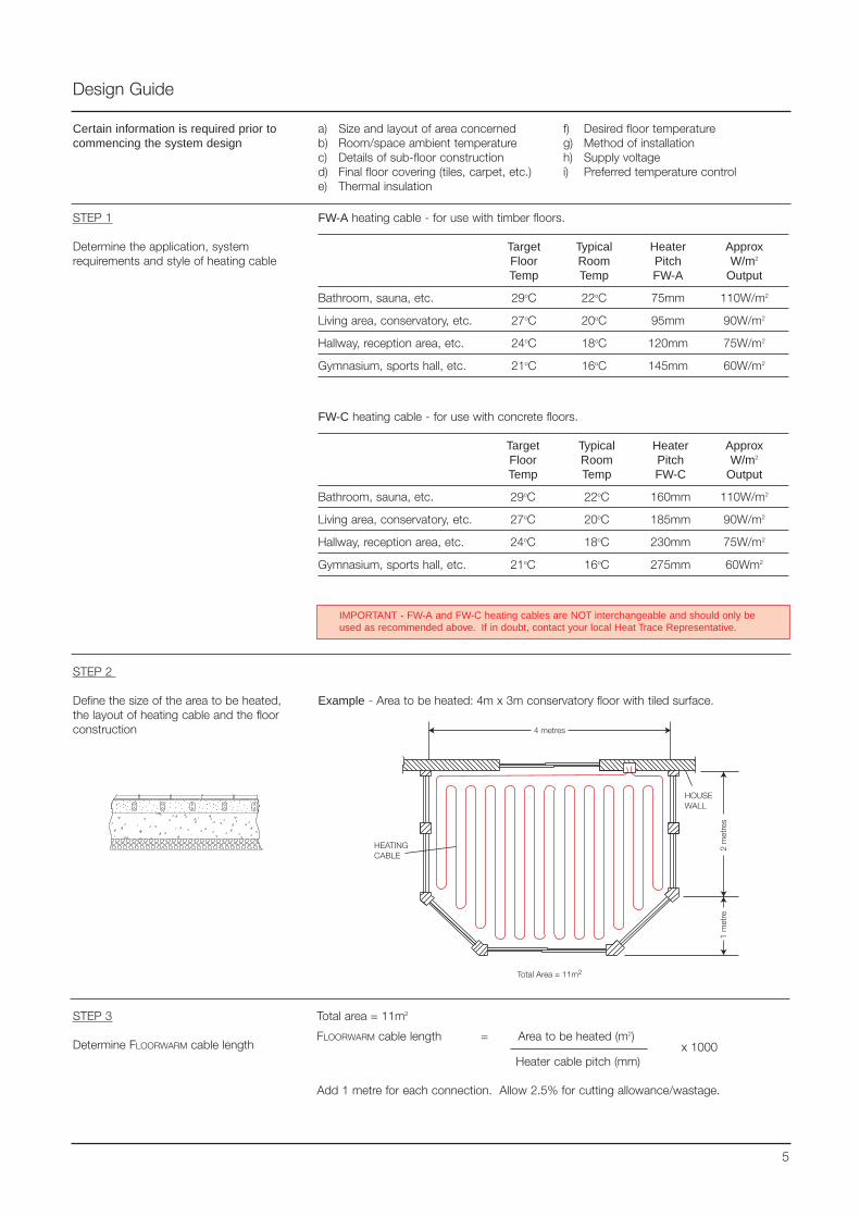
Design Guide
STEP 1
Determine the application, systemrequirements and style of heating cable
FW-A heating cable - for use with timber floors.
Target Typical Heater ApproxFloor Room Pitch W/m2
Temp Temp FW-A Output
Bathroom, sauna, etc. 29oC 22oC 75mm 110W/m2
Living area, conservatory, etc. 27oC 20oC 95mm 90W/m2
Hallway, reception area, etc. 24oC 18oC 120mm 75W/m2
Gymnasium, sports hall, etc. 21oC 16oC 145mm 60W/m2
Certain information is required prior tocommencing the system design
a) Size and layout of area concernedb) Room/space ambient temperaturec) Details of sub-floor constructiond) Final floor covering (tiles, carpet, etc.)e) Thermal insulation
f) Desired floor temperatureg) Method of installationh) Supply voltagei) Preferred temperature control
STEP 2
Define the size of the area to be heated,the layout of heating cable and the floorconstruction
Example - Area to be heated: 4m x 3m conservatory floor with tiled surface.
5
STEP 3
Determine FLOORWARM cable length
Total area = 11m2
FLOORWARM cable length = Area to be heated (m2)x 1000
Heater cable pitch (mm)
Add 1 metre for each connection. Allow 2.5% for cutting allowance/wastage.
IMPORTANT - FW-A and FW-C heating cables are NOT interchangeable and should only beused as recommended above. If in doubt, contact your local Heat Trace Representative.
FW-C heating cable - for use with concrete floors.
Target Typical Heater ApproxFloor Room Pitch W/m2
Temp Temp FW-C Output
Bathroom, sauna, etc. 29oC 22oC 160mm 110W/m2
Living area, conservatory, etc. 27oC 20oC 185mm 90W/m2
Hallway, reception area, etc. 24oC 18oC 230mm 75W/m2
Gymnasium, sports hall, etc. 21oC 16oC 275mm 60Wm2
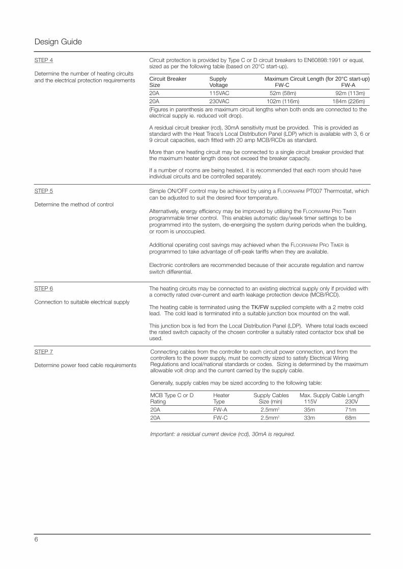
STEP 6
Connection to suitable electrical supply
The heating circuits may be connected to an existing electrical supply only if provided witha correctly rated over-current and earth leakage protection device (MCB/RCD).
The heating cable is terminated using the TK/FW supplied complete with a 2 metre coldlead. The cold lead is terminated into a suitable junction box mounted on the wall.
This junction box is fed from the Local Distribution Panel (LDP). Where total loads exceedthe rated switch capacity of the chosen controller a suitably rated contactor box shall beused.
STEP 7
Determine power feed cable requirements
Connecting cables from the controller to each circuit power connection, and from thecontrollers to the power supply, must be correctly sized to satisfy Electrical WiringRegulations and local/national standards or codes. Sizing is determined by the maximumallowable volt drop and the current carried by the supply cable.
Generally, supply cables may be sized according to the following table:
MCB Type C or D Heater Supply Cables Max. Supply Cable LengthRating Type Size (min) 115V 230V20A FW-A 2.5mm2 35m 71m20A FW-C 2.5mm2 33m 68m
Important: a residual current device (rcd), 30mA is required.
Design Guide
STEP 5
Determine the method of control
Simple ON/OFF control may be achieved by using a FLOORWARM PT007 Thermostat, whichcan be adjusted to suit the desired floor temperature.
Alternatively, energy efficiency may be improved by utilising the FLOORWARM PRO TIMER
programmable timer control. This enables automatic day/week timer settings to beprogrammed into the system, de-energising the system during periods when the building,or room is unoccupied.
Additional operating cost savings may achieved when the FLOORWARM PRO TIMER isprogrammed to take advantage of off-peak tariffs when they are available.
Electronic controllers are recommended because of their accurate regulation and narrowswitch differential.
6
STEP 4
Determine the number of heating circuitsand the electrical protection requirements
Circuit protection is provided by Type C or D circuit breakers to EN60898:1991 or equal,sized as per the following table (based on 20°C start-up).
Circuit Breaker Supply Maximum Circuit Length (for 20°C start-up)Size Voltage FW-C FW-A
20A 115VAC 52m (58m) 92m (113m)20A 230VAC 102m (116m) 184m (226m)(Figures in parenthesis are maximum circuit lengths when both ends are connected to theelectrical supply ie. reduced volt drop).
A residual circuit breaker (rcd), 30mA sensitivity must be provided. This is provided asstandard with the Heat Trace’s Local Distribution Panel (LDP) which is available with 3, 6 or9 circuit capacities, each fitted with 20 amp MCB/RCDs as standard.
More than one heating circuit may be connected to a single circuit breaker provided thatthe maximum heater length does not exceed the breaker capacity.
If a number of rooms are being heated, it is recommended that each room should haveindividual circuits and be controlled separately.
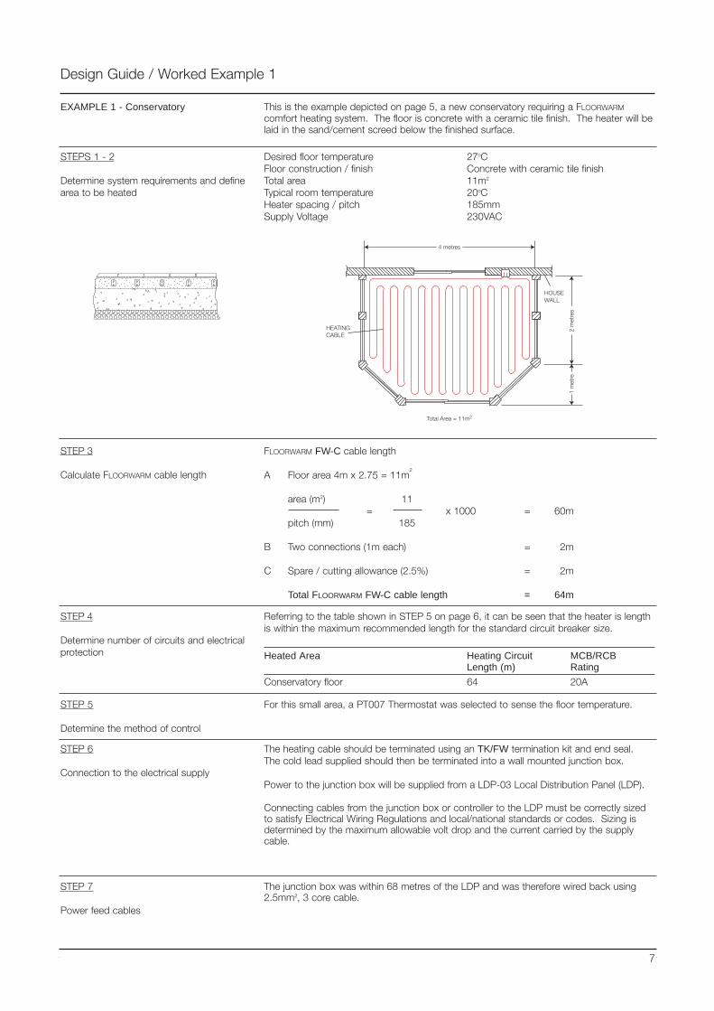
Design Guide / Worked Example 1
This is the example depicted on page 5, a new conservatory requiring a FLOORWARM
comfort heating system. The floor is concrete with a ceramic tile finish. The heater will belaid in the sand/cement screed below the finished surface.
EXAMPLE 1 - Conservatory
Desired floor temperature 27oCFloor construction / finish Concrete with ceramic tile finishTotal area 11m2
Typical room temperature 20oCHeater spacing / pitch 185mmSupply Voltage 230VAC
STEP 3
Calculate FLOORWARM cable length
FLOORWARM FW-C cable length
A Floor area 4m x 2.75 = 11m2
area (m2) 11= x 1000 = 60m
pitch (mm) 185
B Two connections (1m each) = 2m
C Spare / cutting allowance (2.5%) = 2m
Total FLOORWARM FW-C cable length = 64m
STEP 4
Determine number of circuits and electricalprotection
Referring to the table shown in STEP 5 on page 6, it can be seen that the heater is lengthis within the maximum recommended length for the standard circuit breaker size.
Heated Area Heating Circuit MCB/RCBLength (m) Rating
Conservatory floor 64 20A
STEP 5
Determine the method of control
For this small area, a PT007 Thermostat was selected to sense the floor temperature.
STEP 6
Connection to the electrical supply
The heating cable should be terminated using an TK/FW termination kit and end seal.The cold lead supplied should then be terminated into a wall mounted junction box.
Power to the junction box will be supplied from a LDP-03 Local Distribution Panel (LDP).
Connecting cables from the junction box or controller to the LDP must be correctly sizedto satisfy Electrical Wiring Regulations and local/national standards or codes. Sizing isdetermined by the maximum allowable volt drop and the current carried by the supplycable.
STEPS 1 - 2
Determine system requirements and definearea to be heated
7
STEP 7
Power feed cables
The junction box was within 68 metres of the LDP and was therefore wired back using2.5mm2, 3 core cable.
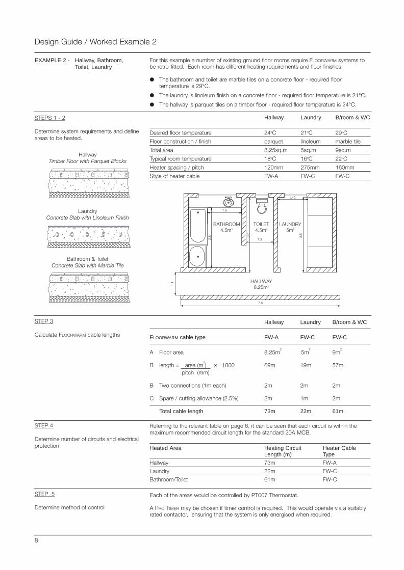
For this example a number of existing ground floor rooms require FLOORWARM systems tobe retro-fitted. Each room has different heating requirements and floor finishes.
The bathroom and toilet are marble tiles on a concrete floor - required floortemperature is 29°C.
The laundry is linoleum finish on a concrete floor - required floor temperature is 21°C.
The hallway is parquet tiles on a timber floor - required floor temperature is 24°C.
Design Guide / Worked Example 2
EXAMPLE 2 - Hallway, Bathroom,Toilet, Laundry
STEPS 1 - 2
Determine system requirements and defineareas to be heated.
Hallway Laundry B/room & WC
Desired floor temperature 24oC 21oC 29oC
Floor construction / finish parquet linoleum marble tile
Total area 8.25sq.m 5sq.m 9sq.m
Typical room temperature 18oC 16oC 22oC
Heater spacing / pitch 120mm 275mm 160mm
Style of heater cable FW-A FW-C FW-C
STEP 3
Calculate FLOORWARM cable lengths
Hallway Laundry B/room & WC
FLOORWARM cable type FW-A FW-C FW-C
A Floor area 8.25m2
5m2
9m2
B length = area (m2) x 1000 69m 19m 57m
pitch (mm)
B Two connections (1m each) 2m 2m 2m
C Spare / cutting allowance (2.5%) 2m 1m 2m
Total cable length 73m 22m 61m
STEP 4
Determine number of circuits and electricalprotection
Referring to the relevant table on page 6, it can be seen that each circuit is within themaximum recommended circuit length for the standard 20A MCB.
Heated Area Heating Circuit Heater CableLength (m) Type
Hallway 73m FW-A
Laundry 22m FW-C
Bathroom/Toilet 61m FW-C
Each of the areas would be controlled by PT007 Thermostat.
A PRO TIMER may be chosen if timer control is required. This would operate via a suitablyrated contactor, ensuring that the system is only energised when required.
STEP 5
Determine method of control
8
Bathroom & ToiletConcrete Slab with Marble Tile
LaundryConcrete Slab with Linoleum Finish
HallwayTimber Floor with Parquet Blocks

Design Guide / Worked Example 2
STEP 6
Connection to electrical supply
The heating cables are terminated using TK/FW termination kits, complete with cold leads.Each cold lead is terminated into the wall mounted junction box using the plastic conduitordered separately.
Circuits may be connected to an electrical supply only if provided with a correctly ratedover-current and earth leakage protection device (MCB / RCD).
In this instance, a Heat Trace 3 way Local Distribution Panel (LDP03) is selected.
9
STEP 7
Determine power feed cable requirements
Determine power feed cables using the table provided in STEP 7 on page 6.
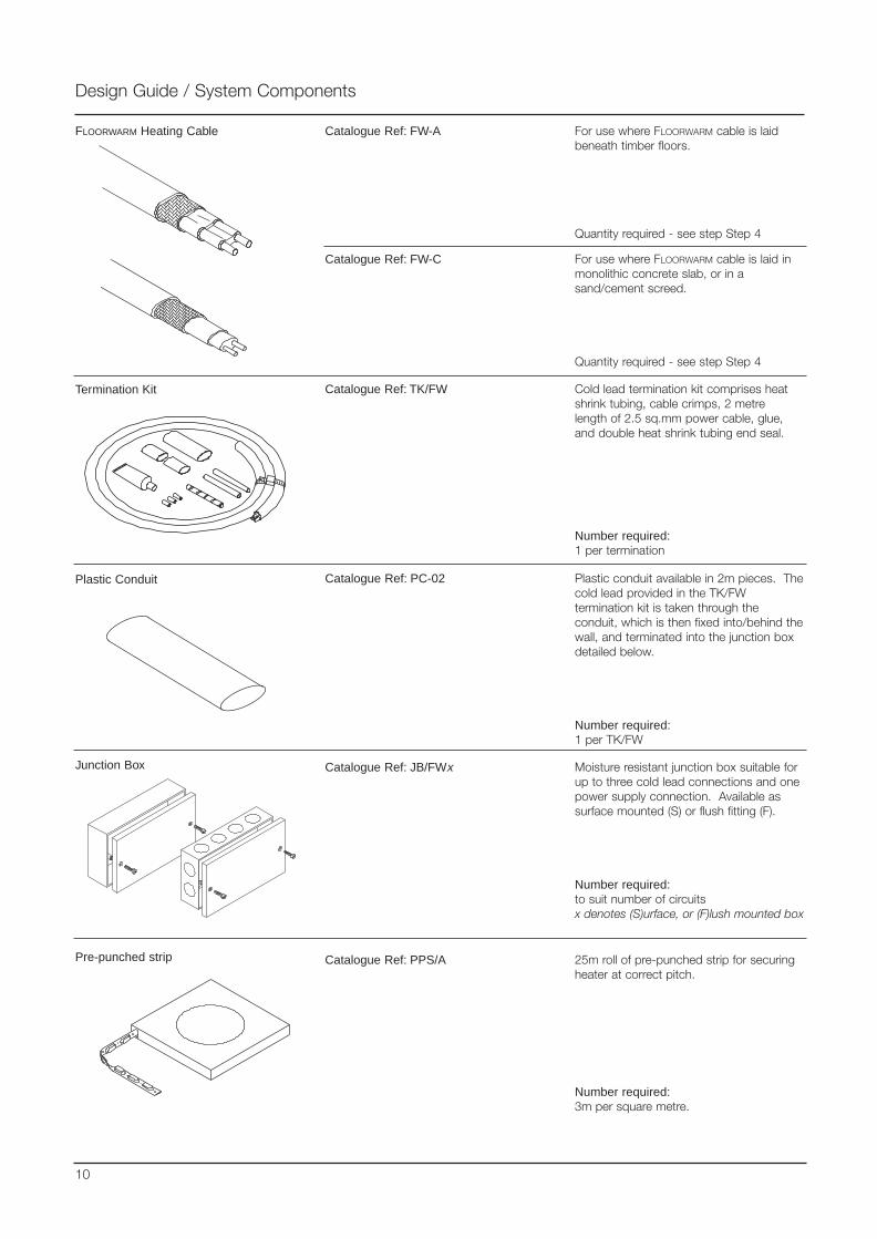
Design Guide / System Components
FLOORWARM Heating Cable
Termination Kit
Junction Box Moisture resistant junction box suitable forup to three cold lead connections and onepower supply connection. Available assurface mounted (S) or flush fitting (F).
Number required:to suit number of circuitsx denotes (S)urface, or (F)lush mounted box
Cold lead termination kit comprises heatshrink tubing, cable crimps, 2 metrelength of 2.5 sq.mm power cable, glue,and double heat shrink tubing end seal.
Number required:1 per termination
For use where FLOORWARM cable is laidbeneath timber floors.
Quantity required - see step Step 4
25m roll of pre-punched strip for securingheater at correct pitch.
Number required:3m per square metre.
Pre-punched strip
Catalogue Ref: FW-A
Catalogue Ref: TK/FW
Catalogue Ref: PPS/A
Catalogue Ref: JB/FWx
10
Catalogue Ref: FW-C For use where FLOORWARM cable is laid inmonolithic concrete slab, or in asand/cement screed.
Quantity required - see step Step 4
Plastic Conduit Plastic conduit available in 2m pieces. Thecold lead provided in the TK/FWtermination kit is taken through theconduit, which is then fixed into/behind thewall, and terminated into the junction boxdetailed below.
Number required:1 per TK/FW
Catalogue Ref: PC-02
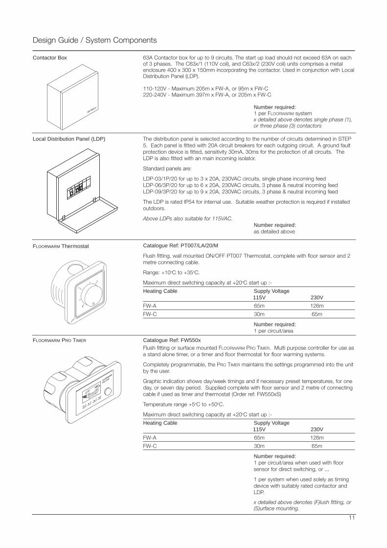
Contactor Box
Local Distribution Panel (LDP) The distribution panel is selected according to the number of circuits determined in STEP5. Each panel is fitted with 20A circuit breakers for each outgoing circuit. A ground faultprotection device is fitted, sensitivity 30mA, 30ms for the protection of all circuits. TheLDP is also fitted with an main incoming isolator.
Standard panels are:
LDP-03/1P/20 for up to 3 x 20A, 230VAC circuits, single phase incoming feedLDP-06/3P/20 for up to 6 x 20A, 230VAC circuits, 3 phase & neutral incoming feedLDP-09/3P/20 for up to 9 x 20A, 230VAC circuits, 3 phase & neutral incoming feed
The LDP is rated IP54 for internal use. Suitable weather protection is required if installedoutdoors.
Above LDPs also suitable for 115VAC.Number required:as detailed above
FLOORWARM Thermostat
11
Flush fitting, wall mounted ON/OFF PT007 Thermostat, complete with floor sensor and 2metre connecting cable.
Range: +10oC to +35oC.
Maximum direct switching capacity at +20oC start up :-
Heating Cable Supply Voltage115V 230V
FW-A 65m 126m
FW-C 30m 65m
Number required:1 per circuit/area
Flush fitting or surface mounted FLOORWARM PRO TIMER. Multi purpose controller for use asa stand alone timer, or a timer and floor thermostat for floor warming systems.
Completely programmable, the PRO TIMER maintains the settings programmed into the unitby the user.
Graphic indication shows day/week timings and if necessary preset temperatures, for oneday, or seven day period. Supplied complete with floor sensor and 2 metre of connectingcable if used as timer and thermostat (Order ref: FW550xS)
Temperature range +5oC to +50oC.
Maximum direct switching capacity at +20oC start up :-
Heating Cable Supply Voltage115V 230V
FW-A 65m 126m
FW-C 30m 65m
Number required:1 per circuit/area when used with floorsensor for direct switching, or ...
1 per system when used solely as timingdevice with suitably rated contactor andLDP.
x detailed above denotes (F)lush fitting, or(S)urface mounting.
Design Guide / System Components
FLOORWARM PRO TIMER
Catalogue Ref: PT007/LA/20/M
Catalogue Ref: FW550x
63A Contactor box for up to 9 circuits. The start up load should not exceed 63A on eachof 3 phases. The C63x/1 (110V coil), and C63x/2 (230V coil) units comprises a metalenclosure 400 x 300 x 150mm incorporating the contactor. Used in conjunction with LocalDistribution Panel (LDP).
110-120V - Maximum 205m x FW-A, or 95m x FW-C220-240V - Maximum 397m x FW-A, or 205m x FW-C
Number required:1 per FLOORWARM systemx detailed above denotes single phase (1), or three phase (3) contactors
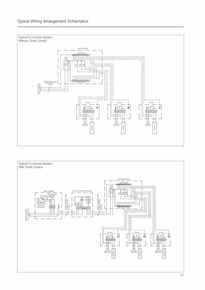
Typical Wiring Arrangement Schematics
Typical FLOORWARM SystemWithout Timer Control
Typical FLOORWARM SystemWith Timer Control
12
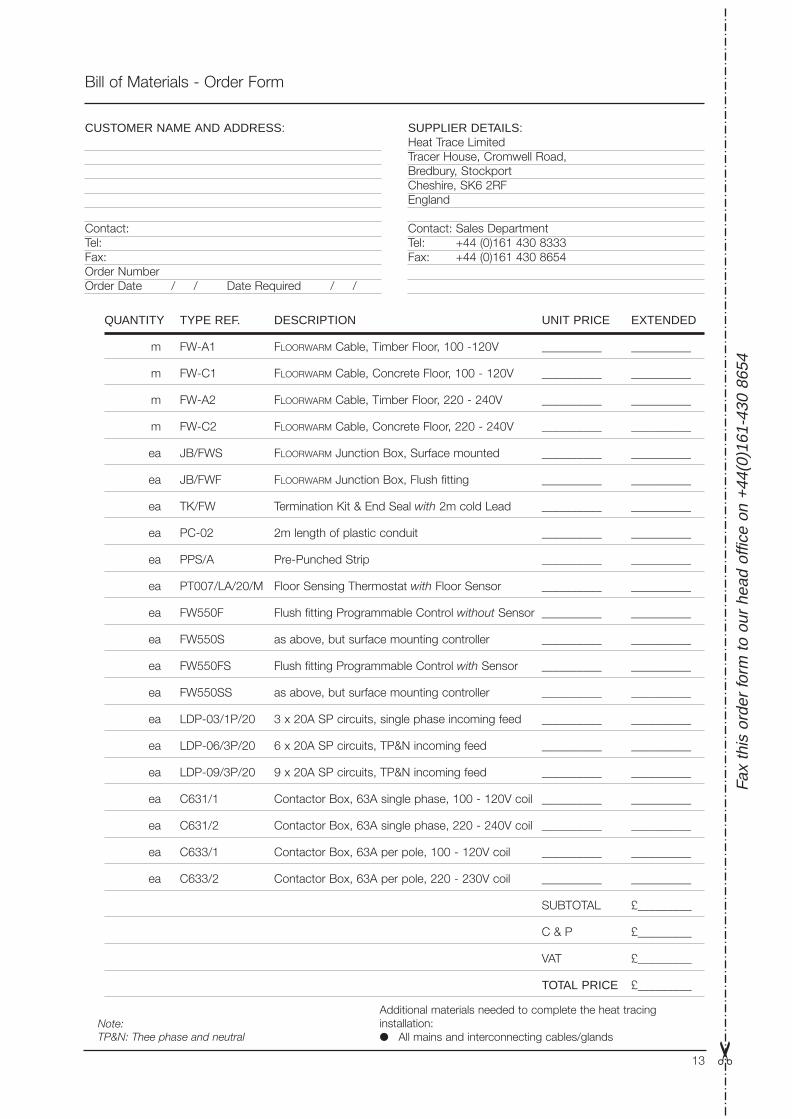
Bill of Materials - Order Form
Fax
this
ord
er fo
rm to
our
hea
d of
fice
on +
44(0
)161
-430
865
4
Additional materials needed to complete the heat tracinginstallation: All mains and interconnecting cables/glands
QUANTITY TYPE REF. DESCRIPTION UNIT PRICE EXTENDED
m FW-A1 FLOORWARM Cable, Timber Floor, 100 -120V __________ __________
m FW-C1 FLOORWARM Cable, Concrete Floor, 100 - 120V __________ __________
m FW-A2 FLOORWARM Cable, Timber Floor, 220 - 240V __________ __________
m FW-C2 FLOORWARM Cable, Concrete Floor, 220 - 240V __________ __________
ea JB/FWS FLOORWARM Junction Box, Surface mounted __________ __________
ea JB/FWF FLOORWARM Junction Box, Flush fitting __________ __________
ea TK/FW Termination Kit & End Seal with 2m cold Lead __________ __________
ea PC-02 2m length of plastic conduit __________ __________
ea PPS/A Pre-Punched Strip __________ __________
ea PT007/LA/20/M Floor Sensing Thermostat with Floor Sensor __________ __________
ea FW550F Flush fitting Programmable Control without Sensor __________ __________
ea FW550S as above, but surface mounting controller __________ __________
ea FW550FS Flush fitting Programmable Control with Sensor __________ __________
ea FW550SS as above, but surface mounting controller __________ __________
ea LDP-03/1P/20 3 x 20A SP circuits, single phase incoming feed __________ __________
ea LDP-06/3P/20 6 x 20A SP circuits, TP&N incoming feed __________ __________
ea LDP-09/3P/20 9 x 20A SP circuits, TP&N incoming feed __________ __________
ea C631/1 Contactor Box, 63A single phase, 100 - 120V coil __________ __________
ea C631/2 Contactor Box, 63A single phase, 220 - 240V coil __________ __________
ea C633/1 Contactor Box, 63A per pole, 100 - 120V coil __________ __________
ea C633/2 Contactor Box, 63A per pole, 220 - 230V coil __________ __________
SUBTOTAL £_________
C & P £_________
VAT £_________
TOTAL PRICE £_________
CUSTOMER NAME AND ADDRESS:
Contact:Tel:Fax:Order NumberOrder Date / / Date Required / /
SUPPLIER DETAILS:Heat Trace LimitedTracer House, Cromwell Road,Bredbury, StockportCheshire, SK6 2RFEngland
Contact: Sales DepartmentTel: +44 (0)161 430 8333Fax: +44 (0)161 430 8654
13
Note:TP&N: Thee phase and neutral

Tracer House, Cromwell Road, Bredbury, Stockport, Cheshire, SK6 2RF, U.K.Tel: +44(0)161-430 8333 Fax: +44(0)161-430 8654 http://www.heat-trace.com
The information given herein, including drawings, illustrations and schematics (which are intended for illustration purposes only), is believed to be reliable. However, Heat Trace Ltd makes nowarranties as to its accuracy or completeness and disclaims any liability in connection with its use. Users of Heat Trace Ltd products should make their own evaluation to determine the suitabilityof each such product for specific applications. In no way will Heat Trace Ltd be liable for any damages arising out of the misuse, resale or use of the product.
PD
G06
0 06
/00
Presented by:
BS EN ISO 9001 Certificate No. 0160
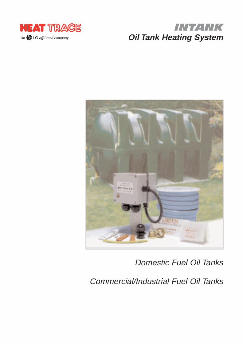
INTANKOil Tank Heating SystemAn LG affiliated company
Domestic Fuel Oil Tanks
Commercial/Industrial Fuel Oil Tanks
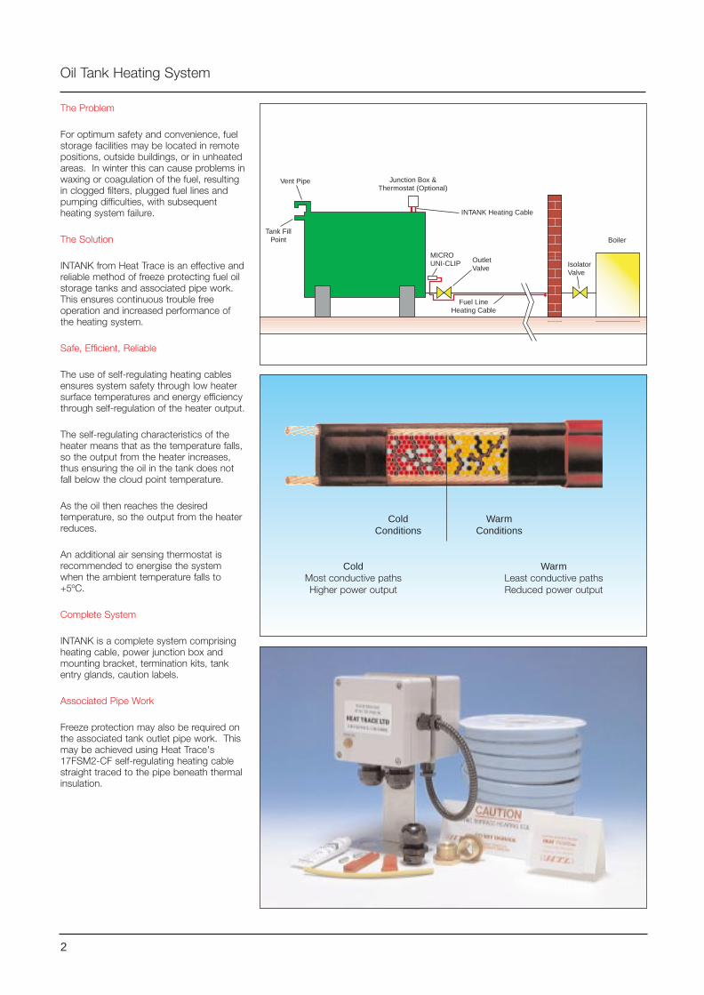
The Problem
For optimum safety and convenience, fuelstorage facilities may be located in remotepositions, outside buildings, or in unheatedareas. In winter this can cause problems inwaxing or coagulation of the fuel, resultingin clogged filters, plugged fuel lines andpumping difficulties, with subsequentheating system failure.
The Solution
INTANK from Heat Trace is an effective andreliable method of freeze protecting fuel oilstorage tanks and associated pipe work.This ensures continuous trouble freeoperation and increased performance ofthe heating system.
Safe, Efficient, Reliable
The use of self-regulating heating cablesensures system safety through low heatersurface temperatures and energy efficiencythrough self-regulation of the heater output.
The self-regulating characteristics of theheater means that as the temperature falls,so the output from the heater increases,thus ensuring the oil in the tank does notfall below the cloud point temperature.
As the oil then reaches the desiredtemperature, so the output from the heaterreduces.
An additional air sensing thermostat isrecommended to energise the systemwhen the ambient temperature falls to+5ºC.
Complete System
INTANK is a complete system comprisingheating cable, power junction box andmounting bracket, termination kits, tankentry glands, caution labels.
Associated Pipe Work
Freeze protection may also be required onthe associated tank outlet pipe work. Thismay be achieved using Heat Trace's17FSM2-CF self-regulating heating cablestraight traced to the pipe beneath thermalinsulation.
Oil Tank Heating System
Junction Box &Thermostat (Optional)
Vent Pipe
Tank FillPoint
MICROUNI-CLIP Outlet
Valve IsolatorValve
Boiler
Fuel LineHeating Cable
INTANK Heating Cable
2
ColdConditions
WarmConditions
ColdMost conductive pathsHigher power output
WarmLeast conductive pathsReduced power output
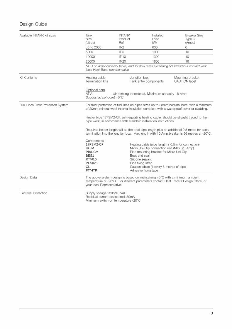
Design Guide
Tank INTANK Installed Breaker SizeSize Product Load Type C(Litres) Ref (W) (Amps)up to 2000 IT-2 600 65000 IT-5 1000 1010000 IT-10 1300 1020000 IT-20 1800 16NB. For larger capacity tanks, and for flow rates exceeding 500litres/hour contact yourlocal Heat Trace representative
Available INTANK kit sizes
Kit Contents
Fuel Lines Frost Protection System For frost protection of fuel lines on pipes sizes up to 38mm nominal bore, with a minimumof 20mm mineral wool thermal insulation complete with a waterproof cover or cladding.
Heater type 17FSM2-CF, self-regulating heating cable, should be straight traced to thepipe work, in accordance with standard installation instructions.
Required heater length will be the total pipe length plus an additional 0.5 metre for eachtermination into the junction box. Max length with 10 Amp breaker is 56 metres at -20°C.
Components17FSM2-CF Heating cable (pipe length + 0.5m for connection)UC/M Micro Uni-Clip connection unit (Max. 20 Amp)PB/UCM Pipe mounting bracket for Micro Uni-ClipBES1 Boot end seal RTV0.5 Silicone sealantPFS025 Pipe fixing strap CL Caution labels (1 every 6 metres of pipe)FT/HTP Adhesive fixing tape
Heating cable Junction box Mounting bracketTermination kits Tank entry components CAUTION label
Optional ItemAT-A air sensing thermostat. Maximum capacity 16 Amp.Suggested set-point +5°C
Design Data The above system design is based on maintaining +5°C with a minimum ambienttemperature of -20°C. For different parameters contact Heat Trace's Design Office, oryour local Representative.
Electrical Protection Supply voltage 220/240 VACResidual current device (rcd) 30mAMinimum switch-on temperature -20°C
3
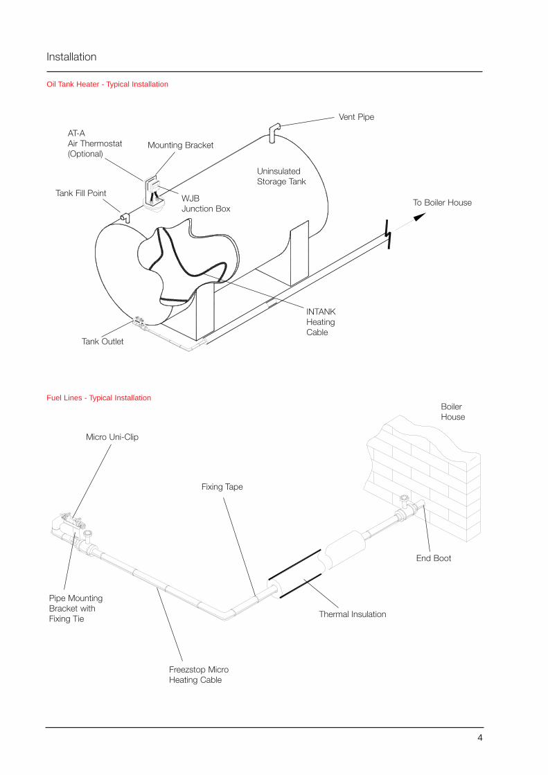
Oil Tank Heater - Typical Installation
Installation
Fuel Lines - Typical Installation
Vent Pipe
To Boiler House
UninsulatedStorage Tank
Mounting Bracket
Tank Fill Point
Tank Outlet
WJBJunction Box
AT-AAir Thermostat(Optional)
INTANKHeatingCable
Micro Uni-Clip
BoilerHouse
Freezstop MicroHeating Cable
Fixing Tape
Thermal Insulation
Pipe MountingBracket withFixing Tie
End Boot
4
Bill of Materials - Order Form
Additional materials needed to complete the heat tracinginstallation:
All mains and interconnecting cables/glands Thermal Insulation
QUANTITY TYPE REF. DESCRIPTION UNIT PRICE EXTENDED
OIL TANK HEATER
pcs IT-2 600W kit for up to 2000 litre tank __________ __________
pcs IT-5 1000W kit 5000 litre tank __________ __________
pcs IT-10 1300W kit 10000 litre tank __________ __________
pcs IT-20 1800W kit 20000 litre tank __________ __________
FUEL LINE HEATER
m 17FSM2-CF Heating tape (pipe length + 0.5m per termination) __________ __________
pcs UC/M Micro Uni-Clip Connector __________ __________
pcs PB/UCM Micro Uni-Clip Pipe Mounting Bracket __________ __________
pcs BES1 End Seal __________ __________
pcs RTV0.5 End Seal Adhesive __________ __________
pcs NT/SF Fixing tie (1 per PB/UCM) __________ __________
pcs CL Caution Labels (1 per 6m of heat traced pipework) __________ __________
pcs FT/HTP Adhesive PVC fixing tape, 12mm x 33m __________ __________
THERMOSTAT CONTROL (Optional)
ea AT-A Air sensing thermostat, 16A single phase max __________ __________
SUBTOTAL £_________
C & P £_________
VAT £_________
TOTAL PRICE £_________
CUSTOMER NAME AND ADDRESS:
Contact:Tel:Fax:Order NumberOrder Date / / Date Required / /
SUPPLIER DETAILS:Heat Trace LimitedTracer House, Cromwell Road,Bredbury, StockportCheshire, SK6 2RFEngland
Contact: Sales DepartmentTel: +44 (0)161 430 8333Fax: +44 (0)161 430 8654
5

Tracer House, Cromwell Road, Bredbury, Stockport, Cheshire, SK6 2RF, U.K.Tel: +44(0)161-430 8333 Fax: +44(0)161-430 8654 http://www.heat-trace.com
The information given herein, including drawings, illustrations and schematics (which are intended for illustration purposes only), is believed to be reliable. However, Heat Trace Ltd makes nowarranties as to its accuracy or completeness and disclaims any liability in connection with its use. Users of Heat Trace Ltd products should make their own evaluation to determine the suitabilityof each such product for specific applications. In no way will Heat Trace Ltd be liable for any damages arising out of the misuse, resale or use of the product.
PD
G07
0 12
/99
Presented by:
BS EN ISO 9001 Certificate No. 0160
RHT RAIL HEATERRail & Switch Point
Heating System
Pre-Terminated Lengthsor Cut-to-Length from the Reel
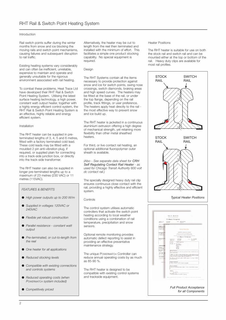
Introduction
Rail switch points suffer during the wintermonths from snow and ice blocking themoving rails and switch point mechanisms,causing failures and subsequent disruptionto rail traffic.
Existing heating systems vary considerablyand can often be inefficient, unreliable,expensive to maintain and operate andgenerally unsuitable for the rigorousenvironment associated with rail heating.
To combat these problems, Heat Trace Ltdhave developed their RHT Rail & SwitchPoint Heating System. Utilising the latestsurface heating technology, a high power,constant watt output heater, together witha highly energy efficient control system, theRHT Rail & Switch Point Heating System isan effective, highly reliable and energyefficient system.
Installation
The RHT heater can be supplied in pre-terminated lengths of 3, 4, 5 and 6 metres,fitted with a factory terminated cold lead.These cold leads may be fitted with amoulded 2 pin anti-vibration plug, ifrequired, or supplied plain for connectinginto a track-side junction box, or directlyinto the track-side transformer.
The RHT heater can also be supplied inlonger pre-terminated lengths up to amaximum of 23 metres (230 VAC) or 11metres (115VAC).
RHT Rail & Switch Point Heating System
2
FEATURES & BENEFITS
High power outputs up to 200 W/m
Supplied in voltages 120VAC or240VAC
Flexible yet robust construction
Parallel resistance - constant wattoutput
Pre-terminated, or cut-to-length fromthe reel
One heater for all applications
Reduced stocking levels
Compatible with existing connectionsand controls systems
Reduced operating costs (whenPOWERMATCH system included)
Competitively priced
STOCKRAIL
SWITCHRAIL
STOCKRAIL
SWITCHRAIL
Typical Heater Positions
Heater Positions
The RHT heater is suitable for use on boththe stock rail and switch rail and can bemounted either at the top or bottom of therail. Heavy duty clips are available formost rail profiles.
Full Product Acceptancefor all Components
Alternatively, the heater may be cut tolength from the reel then terminated andinstalled with the minimum of effort. Thisfacilitates a simple one product stockingcapability. No special equipment isrequired.
Design
The RHT Systems contain all the itemsnecessary to provide protection againstsnow and ice for switch points, swing nosecrossings, switch diamonds, braking areasand high speed curves. The heaters maybe fitted at the base of the rail, or underthe top flange, depending on the railprofile, track fittings, or user preference.The heaters apply heat directly to the rail -the most effective way to prevent snowand ice build up.
The RHT heater is jacketed in a continuousaluminium extrusion offering a high degreeof mechanical strength, yet retaining moreflexibility than other metal sheathedheaters.
For third, or live contact rail heating, anoptional additional fluoropolymer outersheath is available.
(Also - See separate data sheet for CRHSelf Regulating Contact Rail Heater - asused for Chicago Transit Authority 600 voltdc contact rail.)
The specially designed heavy duty rail clipensures continuous close contact with therail, providing a highly effective and efficientsystem.
Controls
The control system utilises automaticcontrollers that activate the switch pointheating according to local weatherconditions using a combination of railtemperature, precipitation and snowsensors.
Optional remote monitoring providesautomatic defect reporting to assist inproviding an effective preventativemaintenance strategy.
The unique POWERMATCH Controller canreduce annual operating costs by as muchas 85-90 %.
The RHT heater is designed to becompatible with existing control systemsand trackside equipment.
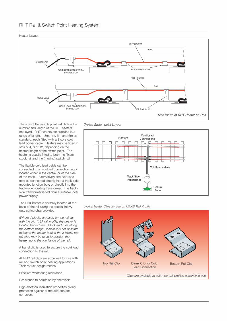
RHT HEATER
RAIL
TOP RAIL CLIP
COLD LEAD CONNECTIONBARREL CLIP
COLD LEAD
RHT Rail & Switch Point Heating System
3
Side Views of RHT Heater on Rail
RHT HEATER
RAIL
BOTTOM RAIL CLIPCOLD LEAD CONNECTIONBARREL CLIP
COLD LEAD
The size of the switch point will dictate thenumber and length of the RHT heatersdeployed. RHT heaters are supplied in arange of lengths - 3m, 4m, 5m and 6m asstandard, each fitted with a 2 core coldlead power cable. Heaters may be fitted insets of 4, 8 or 12, depending on theheated length of the switch point. Theheater is usually fitted to both the (fixed)stock rail and the (moving) switch rail.
The flexible cold lead cable can beconnected to a moulded connection blocklocated either in the centre, or at the sideof the track. Alternatively, the cold leadmay be connected directly into a track-sidemounted junction box, or directly into thetrack-side isolating transformer. The track-side transformer is fed from a suitable localpower supply.
The RHT heater is normally located at thebase of the rail using the special heavyduty spring clips provided.
(Where J blocks are used on the rail, aswith the old 113A rail profile, the heater islocated behind the J block and runs alongthe bottom flange. Where it is not possibleto locate the heater behind the J block, toprail clips may be used to position theheater along the top flange of the rail.)
A barrel clip is used to secure the cold leadconnection to the rail.
All RHC rail clips are approved for use withrail and switch point heating applications.Their robust design means:
Excellent weathering resistance.
Resistance to corrosion by chemicals.
High electrical insulation properties givingprotection against bi-metallic contactcorrosion.
Heater Layout
Heaters
Cold lead cables
Cold LeadConnections
Track Side Transformer
ControlPanel
Typical heater Clips for use on UIC60 Rail Profile
Top Rail Clip Bottom Rail ClipBarrel Clip for ColdLead Connection
Typical Switch point Layout
Clips are available to suit most rail profiles currently in use
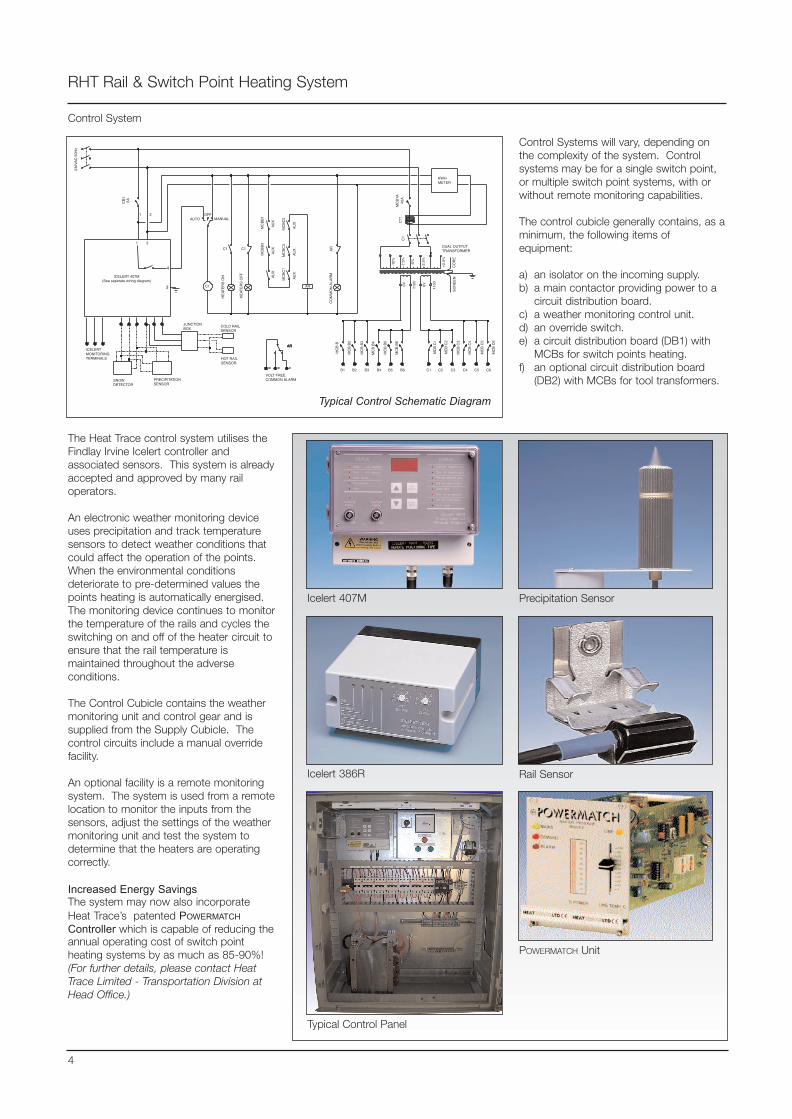
RHT Rail & Switch Point Heating System
4
Control System
The Heat Trace control system utilises theFindlay Irvine Icelert controller andassociated sensors. This system is alreadyaccepted and approved by many railoperators.
An electronic weather monitoring deviceuses precipitation and track temperaturesensors to detect weather conditions thatcould affect the operation of the points.When the environmental conditionsdeteriorate to pre-determined values thepoints heating is automatically energised.The monitoring device continues to monitorthe temperature of the rails and cycles theswitching on and off of the heater circuit toensure that the rail temperature ismaintained throughout the adverseconditions.
The Control Cubicle contains the weathermonitoring unit and control gear and issupplied from the Supply Cubicle. Thecontrol circuits include a manual overridefacility.
An optional facility is a remote monitoringsystem. The system is used from a remotelocation to monitor the inputs from thesensors, adjust the settings of the weathermonitoring unit and test the system todetermine that the heaters are operatingcorrectly.
Increased Energy SavingsThe system may now also incorporateHeat Trace’s patented POWERMATCHController which is capable of reducing theannual operating cost of switch pointheating systems by as much as 85-90%!(For further details, please contact HeatTrace Limited - Transportation Division atHead Office.)
Control Systems will vary, depending onthe complexity of the system. Controlsystems may be for a single switch point,or multiple switch point systems, with orwithout remote monitoring capabilities.
The control cubicle generally contains, as aminimum, the following items ofequipment:
a) an isolator on the incoming supply.b) a main contactor providing power to a
circuit distribution board.c) a weather monitoring control unit.d) an override switch.e) a circuit distribution board (DB1) with
MCBs for switch points heating. f) an optional circuit distribution board
(DB2) with MCBs for tool transformers.
230V
AC
50H
z
CB
16A
1 2
1 2
3
4
AUTO MANUALOFF
C1
C1 C1
MC
BB
1M
CB
B3
AU
XA
UX
AU
X
MC
BC
5M
CB
C3
MC
BC
1
AU
XA
UX
AU
X
AR
CO
MM
ON
ALA
RMICELERT 407M
(See seperate wiring diagram)
CT
1M
CB
1A40
A
AR
C1
VOLT FREECOMMON ALARM
COLD RAILSENSOR
AR
HOT RAILSENSOR
AR
JUNCTIONBOX
PRECIPITATIONSENSOR
SNOWDETECTOR
ICELERTMONITORINGTERMINALS
HE
ATE
RS
ON
HE
ATE
RS
OF
F
KWHMETER
CO
RE
SC
RE
EN
-10%
-7.5
%
-5%
-2.5
%
+2.
5%
MC
B B
MC
B B
2
MC
B B
3
MC
B B
4
MC
B B
5
MC
B B
6
MC
B C
1
MC
B C
2
MC
B C
3
MC
B C
4
MC
B C
5
MC
B C
6
B1 B5B4B3B2 B6 C1 C5C4C3C2 C6
DUAL OUTPUTTRANSFORMERA
R
0V
110V 0V
110V
Typical Control Schematic Diagram
Icelert 407M
Typical Control Panel
Icelert 386R
Precipitation Sensor
Rail Sensor
POWERMATCH Unit
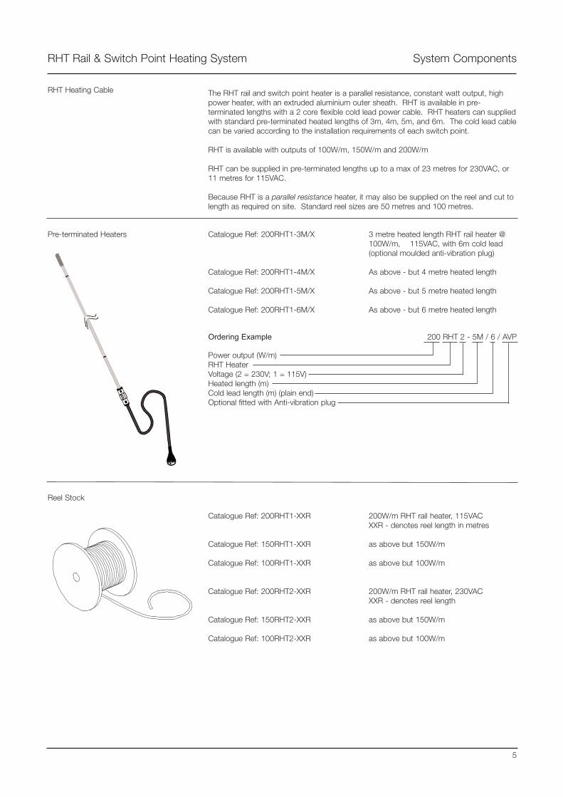
RHT Rail & Switch Point Heating System System Components
RHT Heating Cable
3 metre heated length RHT rail heater @100W/m, 115VAC, with 6m cold lead(optional moulded anti-vibration plug)
As above - but 4 metre heated length
As above - but 5 metre heated length
As above - but 6 metre heated length
Catalogue Ref: 200RHT1-3M/X
Catalogue Ref: 200RHT1-4M/X
Catalogue Ref: 200RHT1-5M/X
Catalogue Ref: 200RHT1-6M/X
The RHT rail and switch point heater is a parallel resistance, constant watt output, highpower heater, with an extruded aluminium outer sheath. RHT is available in pre-terminated lengths with a 2 core flexible cold lead power cable. RHT heaters can suppliedwith standard pre-terminated heated lengths of 3m, 4m, 5m, and 6m. The cold lead cablecan be varied according to the installation requirements of each switch point.
RHT is available with outputs of 100W/m, 150W/m and 200W/m
RHT can be supplied in pre-terminated lengths up to a max of 23 metres for 230VAC, or11 metres for 115VAC.
Because RHT is a parallel resistance heater, it may also be supplied on the reel and cut tolength as required on site. Standard reel sizes are 50 metres and 100 metres.
Pre-terminated Heaters
Reel Stock
Catalogue Ref: 200RHT1-XXR
Catalogue Ref: 150RHT1-XXR
Catalogue Ref: 100RHT1-XXR
Catalogue Ref: 200RHT2-XXR
Catalogue Ref: 150RHT2-XXR
Catalogue Ref: 100RHT2-XXR
200W/m RHT rail heater, 115VACXXR - denotes reel length in metres
as above but 150W/m
as above but 100W/m
200W/m RHT rail heater, 230VACXXR - denotes reel length
as above but 150W/m
as above but 100W/m
5
Ordering Example 200 RHT 2 - 5M / 6 / AVP
Power output (W/m)RHT HeaterVoltage (2 = 230V; 1 = 115V)Heated length (m)Cold lead length (m) (plain end)Optional fitted with Anti-vibration plug
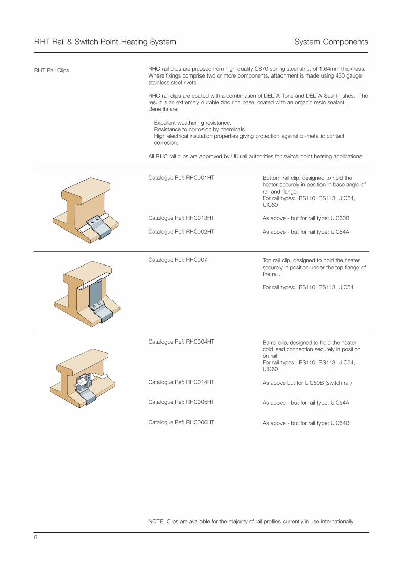
RHT Rail & Switch Point Heating System System Components
6
Catalogue Ref: RHC001HT
Catalogue Ref: RHC013HT
Catalogue Ref: RHC002HT
Bottom rail clip, designed to hold theheater securely in position in base angle ofrail and flange.For rail types: BS110, BS113, UIC54,UIC60
As above - but for rail type: UIC60B
As above - but for rail type: UIC54A
Catalogue Ref: RHC007 Top rail clip, designed to hold the heatersecurely in position under the top flange ofthe rail.
For rail types: BS110, BS113, UIC54
Barrel clip, designed to hold the heatercold lead connection securely in positionon railFor rail types: BS110, BS113, UIC54,UIC60
As above but for UIC60B (switch rail)
As above - but for rail type: UIC54A
As above - but for rail type: UIC54B
Catalogue Ref: RHC004HT
Catalogue Ref: RHC014HT
Catalogue Ref: RHC005HT
Catalogue Ref: RHC006HT
RHT Rail Clips RHC rail clips are pressed from high quality CS70 spring steel strip, of 1.64mm thickness.Where fixings comprise two or more components, attachment is made using 430 gaugestainless steel rivets.
RHC rail clips are coated with a combination of DELTA-Tone and DELTA-Seal finishes. Theresult is an extremely durable zinc rich base, coated with an organic resin sealant.Benefits are:
Excellent weathering resistance.Resistance to corrosion by chemicals.High electrical insulation properties giving protection against bi-metallic contactcorrosion.
All RHC rail clips are approved by UK rail authorities for switch point heating applications.
NOTE Clips are available for the majority of rail profiles currently in use internationally

RHT Rail & Switch Point Heating System System Components
RHT Connecting Blocks
Catalogue Ref: 4WAY/8C-1.5
Catalogue Ref: 4WAY/8C-4.0
4 way connector block for 8 core1.5sq.mm cable
4 way connector block for 8 core4.0sq.mm cable
Catalogue Ref: 8WAY/8C-1.5
Catalogue Ref: 8WAY/8C-4.0
8 way connector block for 8 core1.5sq.mm cable
8 way connector block for 8 core 4sq.mm cable
7
Anti-vibration, plug-in moulded socket block system for RHT rail heater complete withgalvanised steel plate protection covers.
Totally waterproof offering long term reliability.
Quick installation facility reduces connection time.
A system approved by UK rail authorities for switch point heating systems.
Connector blocks can be supplied in kit form for localised assembly, or with pre-moulded8 core cables with lengths of 7 metres to 60 metres
RHT Control Systems Control Systems will vary, depending on the complexity of the system. Controls systemsmay be single switch point, or multi-switch point systems, with or without remotemonitoring capabilities.
A typical control cubicle contains the following items of equipment:
a) an isolator on the incoming supplyb) a main contactor - which is energised by the weather monitoring control unit
and provides power to a circuit distribution boardc) a weather monitoring control unitd) an override switche) a circuit distribution board with MCBs for switch points heating (DB1)f) an optional circuit distribution board with MCBs for tool transformers (DB2)
FULL DETAILS OF CONTROL SYSTEMS ARE AVAILABLE ON REQUEST
NoteAll blocks, both 4 way and 8 way, are generally supplied with moulded in cables, asshown here and fitted with 7 metres of cable.
PD
G09
0 05
/03
DR
AFT
Tracer House, Cromwell Road, Bredbury, Stockport, Cheshire, SK6 2RF, U.K.Tel: +44(0)161-430 8333 Fax: +44(0)161-430 8654 http://www.heat-trace.com
The information given herein, including drawings, illustrations and schematics (which are intended for illustration purposes only), is believed to be reliable. However, Heat Trace Ltd makes nowarranties as to its accuracy or completeness and disclaims any liability in connection with its use. Users of Heat Trace Ltd products should make their own evaluation to determine the suitabilityof each such product for specific applications. In no way will Heat Trace Ltd be liable for any damages arising out of the misuse, resale or use of the product.
Presented by:
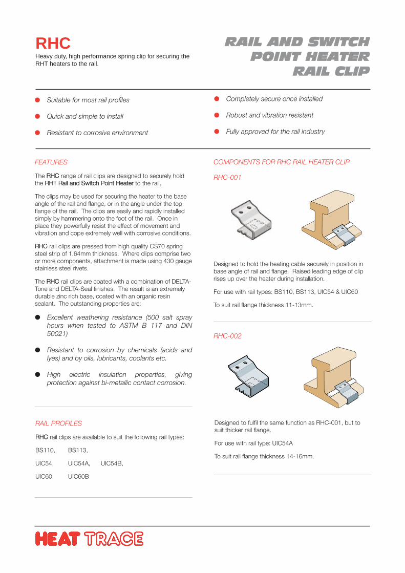
RRAAIILL AANNDD SSWWIITTCCHHPPOOIINNTT HHEEAATTEERR
RRAAIILL CCLLIIPP
RHCHeavy duty, high performance spring clip for securing theRHT heaters to the rail.
FEATURES
The RRHHCC range of rail clips are designed to securely holdthe RRHHTT RRaaiill aanndd SSwwiittcchh PPooiinntt HHeeaatteerr to the rail.
The clips may be used for securing the heater to the baseangle of the rail and flange, or in the angle under the topflange of the rail. The clips are easily and rapidly installedsimply by hammering onto the foot of the rail. Once inplace they powerfully resist the effect of movement andvibration and cope extremely well with corrosive conditions.
RRHHCC rail clips are pressed from high quality CS70 springsteel strip of 1.64mm thickness. Where clips comprise twoor more components, attachment is made using 430 gaugestainless steel rivets.
The RRHHCC rail clips are coated with a combination of DELTA-Tone and DELTA-Seal finishes. The result is an extremelydurable zinc rich base, coated with an organic resinsealant. The outstanding properties are:
Excellent weathering resistance (500 salt sprayhours when tested to ASTM B 117 and DIN50021)
Resistant to corrosion by chemicals (acids andlyes) and by oils, lubricants, coolants etc.
High electric insulation properties, givingprotection against bi-metallic contact corrosion.
Suitable for most rail profiles
Quick and simple to install
Resistant to corrosive environment
Completely secure once installed
Robust and vibration resistant
Fully approved for the rail industry
RAIL PROFILES
RRHHCC rail clips are available to suit the following rail types:
BS110, BS113,
UIC54, UIC54A, UIC54B,
UIC60, UIC60B
RHC-002
Designed to fulfil the same function as RHC-001, but tosuit thicker rail flange.
For use with rail type: UIC54A
To suit rail flange thickness 14-16mm.
RHC-001
Designed to hold the heating cable securely in position inbase angle of rail and flange. Raised leading edge of cliprises up over the heater during installation.
For use with rail types: BS110, BS113, UIC54 & UIC60
To suit rail flange thickness 11-13mm.
COMPONENTS FOR RHC RAIL HEATER CLIP
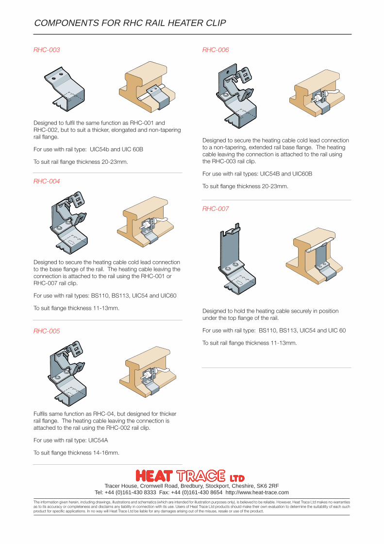
Tracer House, Cromwell Road, Bredbury, Stockport, Cheshire, SK6 2RFTel: +44 (0)161-430 8333 Fax: +44 (0)161-430 8654 http://www.heat-trace.com
The information given herein, including drawings, illustrations and schematics (which are intended for illustration purposes only), is believed to be reliable. However, Heat Trace Ltd makes no warrantiesas to its accuracy or completeness and disclaims any liability in connection with its use. Users of Heat Trace Ltd products should make their own evaluation to determine the suitability of each suchproduct for specific applications. In no way will Heat Trace Ltd be liable for any damages arising out of the misuse, resale or use of the product.
RHC-004
Designed to secure the heating cable cold lead connectionto the base flange of the rail. The heating cable leaving theconnection is attached to the rail using the RHC-001 orRHC-007 rail clip.
For use with rail types: BS110, BS113, UIC54 and UIC60
To suit flange thickness 11-13mm.
RHC-003
Designed to fulfil the same function as RHC-001 andRHC-002, but to suit a thicker, elongated and non-taperingrail flange.
For use with rail type: UIC54b and UIC 60B
To suit rail flange thickness 20-23mm.
RHC-005
RHC-006
Designed to secure the heating cable cold lead connectionto a non-tapering, extended rail base flange. The heatingcable leaving the connection is attached to the rail usingthe RHC-003 rail clip.
For use with rail types: UIC54B and UIC60B
To suit flange thickness 20-23mm.
Fulfils same function as RHC-04, but designed for thickerrail flange. The heating cable leaving the connection isattached to the rail using the RHC-002 rail clip.
For use with rail type: UIC54A
To suit flange thickness 14-16mm.
RHC-007
Designed to hold the heating cable securely in positionunder the top flange of the rail.
For use with rail type: BS110, BS113, UIC54 and UIC 60
To suit rail flange thickness 11-13mm.
COMPONENTS FOR RHC RAIL HEATER CLIP
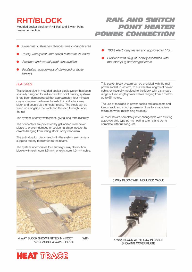
RRAAIILL AANNDD SSWWIITTCCHHPPOOIINNTT HHEEAATTEERR
PPOOWWEERR CCOONNNNEECCTTIIOONN
RHT/BLOCKMoulded socket block for RHT Rail and Switch Pointheater connection
FEATURES
This unique plug-in moulded socket block system has beenspecially designed for rail and switch point heating systems.It has been demonstrated that approximately four minutesonly are required between the rails to install a four wayblock and couple up the heater plugs. The block can bewired up alongside the track and then fed through underthe rail.
The system is totally waterproof, giving long term reliability.
The connectors are protected by galvanised steel coverplates to prevent damage or accidental disconnection byobjects hanging from rolling stock, or by vandalism.
The anti-vibration plugs used with the system are normallysupplied factory terminated to the heater.
The system incorporates four and eight way distributionblocks with eight core 1.5mm², or eight core 4.0mm² cable.
Super fast installation reduces time in danger area
Totally waterproof, immersion tested for 24 hours
Accident and vandal proof construction
Facilitates replacement of damaged or faultyheaters
100% electrically tested and approved to IP68
Supplied with plug kit, or fully asembled withmoulded plug and integral cable
44 WWAAYY BBLLOOCCKK SSHHOOWWNN FFIITTTTEEDD IINN 44 FFOOOOTT WWIITTHH““ZZ”” BBRRAACCKKEETT && CCOOVVEERR PPLLAATTEE
This socket block system can be provided with the mainpower socket in kit form, to suit variable lengths of powercable, or integrally moulded to the block with a standardrange of fixed length power cables ranging from 7 metresup to 65 metres.
The use of moulded-in power cables reduces costs andkeeps track and 4 foot possession time to an absoluteminimum whilst maximising reliability.
All modules are completely inter-changeable with existingapproved strip type points heating sytems and comecomplete with full fixing kits.
44 WWAAYY BBLLOOCCKK WWIITTHH PPLLUUGG--IINN CCAABBLLEESSHHOOWWIINNGG CCOOVVEERR PPLLAATTEE
88 WWAAYY BBLLOOCCKK WWIITTHH MMOOUULLDDEEDD CCAABBLLEE
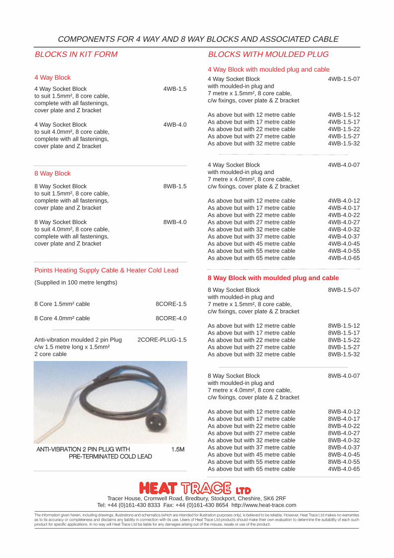
Tracer House, Cromwell Road, Bredbury, Stockport, Cheshire, SK6 2RFTel: +44 (0)161-430 8333 Fax: +44 (0)161-430 8654 http://www.heat-trace.com
The information given herein, including drawings, illustrations and schematics (which are intended for illustration purposes only), is believed to be reliable. However, Heat Trace Ltd makes no warrantiesas to its accuracy or completeness and disclaims any liability in connection with its use. Users of Heat Trace Ltd products should make their own evaluation to determine the suitability of each suchproduct for specific applications. In no way will Heat Trace Ltd be liable for any damages arising out of the misuse, resale or use of the product.
COMPONENTS FOR 4 WAY AND 8 WAY BLOCKS AND ASSOCIATED CABLE
BLOCKS IN KIT FORM BLOCKS WITH MOULDED PLUG
4 Way Socket Block 4WB-1.5to suit 1.5mm², 8 core cable, complete with all fastenings, cover plate and Z bracket
4 Way Socket Block 4WB-4.0to suit 4.0mm², 8 core cable, complete with all fastenings, cover plate and Z bracket
4 Way Block
Points Heating Supply Cable & Heater Cold Lead
(Supplied in 100 metre lengths)
8 Core 1.5mm² cable 8CORE-1.5
8 Core 4.0mm² cable 8CORE-4.0
Anti-vibration moulded 2 pin Plug 2CORE-PLUG-1.5c/w 1.5 metre long x 1.5mm²2 core cable
4 Way Socket Block 4WB-1.5-07with moulded-in plug and 7 metre x 1.5mm², 8 core cable, c/w fixings, cover plate & Z bracket
As above but with 12 metre cable 4WB-1.5-12As above but with 17 metre cable 4WB-1.5-17As above but with 22 metre cable 4WB-1.5-22As above but with 27 metre cable 4WB-1.5-27As above but with 32 metre cable 4WB-1.5-32
4 Way Socket Block 4WB-4.0-07with moulded-in plug and 7 metre x 4.0mm², 8 core cable, c/w fixings, cover plate & Z bracket
As above but with 12 metre cable 4WB-4.0-12As above but with 17 metre cable 4WB-4.0-17As above but with 22 metre cable 4WB-4.0-22As above but with 27 metre cable 4WB-4.0-27As above but with 32 metre cable 4WB-4.0-32As above but with 37 metre cable 4WB-4.0-37As above but with 45 metre cable 4WB-4.0-45As above but with 55 metre cable 4WB-4.0-55As above but with 65 metre cable 4WB-4.0-65
4 Way Block with moulded plug and cable
8 Way Block with moulded plug and cable
8 Way Socket Block 8WB-1.5to suit 1.5mm², 8 core cable, complete with all fastenings, cover plate and Z bracket
8 Way Socket Block 8WB-4.0to suit 4.0mm², 8 core cable, complete with all fastenings, cover plate and Z bracket
8 Way Block
8 Way Socket Block 8WB-1.5-07with moulded-in plug and 7 metre x 1.5mm², 8 core cable, c/w fixings, cover plate & Z bracket
As above but with 12 metre cable 8WB-1.5-12As above but with 17 metre cable 8WB-1.5-17As above but with 22 metre cable 8WB-1.5-22As above but with 27 metre cable 8WB-1.5-27As above but with 32 metre cable 8WB-1.5-32
8 Way Socket Block 8WB-4.0-07with moulded-in plug and 7 metre x 4.0mm², 8 core cable, c/w fixings, cover plate & Z bracket
As above but with 12 metre cable 8WB-4.0-12As above but with 17 metre cable 8WB-4.0-17As above but with 22 metre cable 8WB-4.0-22As above but with 27 metre cable 8WB-4.0-27As above but with 32 metre cable 8WB-4.0-32As above but with 37 metre cable 8WB-4.0-37As above but with 45 metre cable 8WB-4.0-45As above but with 55 metre cable 8WB-4.0-55As above but with 65 metre cable 4WB-4.0-65
AANNTTII--VVIIBBRRAATTIIOONN 22 PPIINN PPLLUUGG WWIITTHH 11..55MMPPRREE--TTEERRMMIINNAATTEEDD CCOOLLDD LLEEAADD
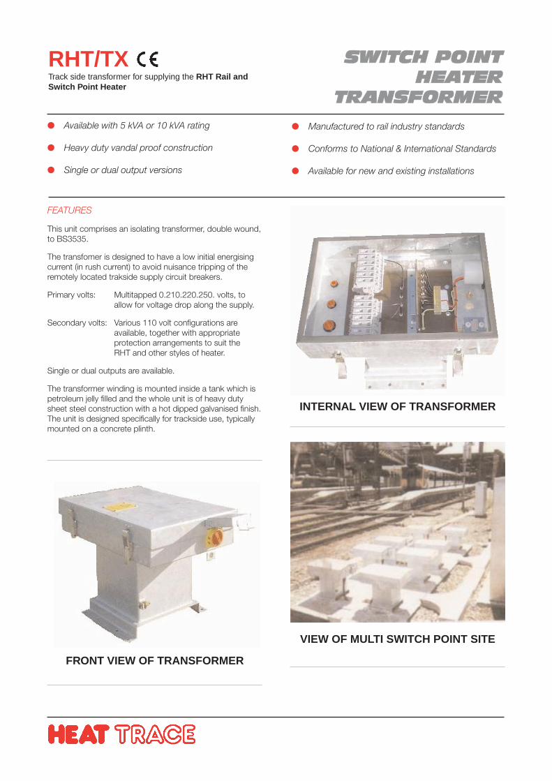
SSWWIITTCCHH PPOOIINNTTHHEEAATTEERR
TTRRAANNSSFFOORRMMEERR
RHT/TXTrack side transformer for supplying the RHT Rail andSwitch Point Heater
FEATURES
This unit comprises an isolating transformer, double wound,to BS3535.
The transfomer is designed to have a low initial energisingcurrent (in rush current) to avoid nuisance tripping of theremotely located trakside supply circuit breakers.
Primary volts: Multitapped 0.210.220.250. volts, to allow for voltage drop along the supply.
Secondary volts: Various 110 volt configurations are available, together with appropriate protection arrangements to suit the RHT and other styles of heater.
Single or dual outputs are available.
The transformer winding is mounted inside a tank which ispetroleum jelly filled and the whole unit is of heavy dutysheet steel construction with a hot dipped galvanised finish.The unit is designed specifically for trackside use, typicallymounted on a concrete plinth.
Available with 5 kVA or 10 kVA rating
Heavy duty vandal proof construction
Single or dual output versions
Manufactured to rail industry standards
Conforms to National & International Standards
Available for new and existing installations
FRONT VIEW OF TRANSFORMER
INTERNAL VIEW OF TRANSFORMER
VIEW OF MULTI SWITCH POINT SITE
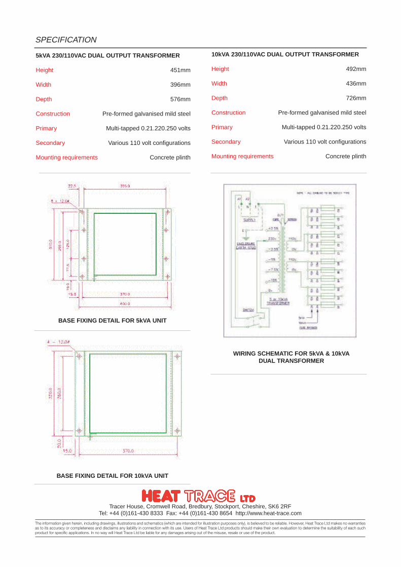
Tracer House, Cromwell Road, Bredbury, Stockport, Cheshire, SK6 2RFTel: +44 (0)161-430 8333 Fax: +44 (0)161-430 8654 http://www.heat-trace.com
The information given herein, including drawings, illustrations and schematics (which are intended for illustration purposes only), is believed to be reliable. However, Heat Trace Ltd makes no warrantiesas to its accuracy or completeness and disclaims any liability in connection with its use. Users of Heat Trace Ltd products should make their own evaluation to determine the suitability of each suchproduct for specific applications. In no way will Heat Trace Ltd be liable for any damages arising out of the misuse, resale or use of the product.
SPECIFICATION
5kVA 230/110VAC DUAL OUTPUT TRANSFORMER
Height 451mm
Width 396mm
Depth 576mm
Construction Pre-formed galvanised mild steel
Primary Multi-tapped 0.21.220.250 volts
Secondary Various 110 volt configurations
Mounting requirements Concrete plinth
10kVA 230/110VAC DUAL OUTPUT TRANSFORMER
Height 492mm
Width 436mm
Depth 726mm
Construction Pre-formed galvanised mild steel
Primary Multi-tapped 0.21.220.250 volts
Secondary Various 110 volt configurations
Mounting requirements Concrete plinth
BASE FIXING DETAIL FOR 5kVA UNIT
WIRING SCHEMATIC FOR 5kVA & 10kVADUAL TRANSFORMER
BASE FIXING DETAIL FOR 10kVA UNIT
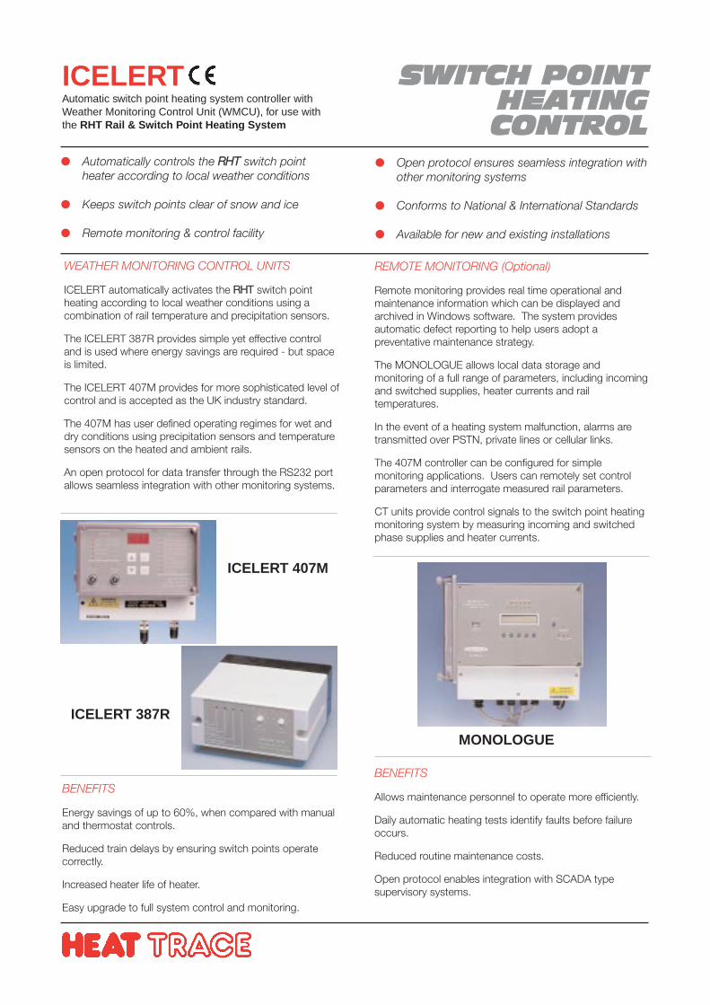
SSWWIITTCCHH PPOOIINNTT HHEEAATTIINNGGCCOONNTTRROOLL
ICELERTAutomatic switch point heating system controller withWeather Monitoring Control Unit (WMCU), for use withthe RHT Rail & Switch Point Heating System
WEATHER MONITORING CONTROL UNITS
ICELERT automatically activates the RRHHTT switch pointheating according to local weather conditions using acombination of rail temperature and precipitation sensors.
The ICELERT 387R provides simple yet effective controland is used where energy savings are required - but spaceis limited.
The ICELERT 407M provides for more sophisticated level ofcontrol and is accepted as the UK industry standard.
The 407M has user defined operating regimes for wet anddry conditions using precipitation sensors and temperaturesensors on the heated and ambient rails.
An open protocol for data transfer through the RS232 portallows seamless integration with other monitoring systems.
Automatically controls the RRHHTT switch pointheater according to local weather conditions
Keeps switch points clear of snow and ice
Remote monitoring & control facility
Open protocol ensures seamless integration withother monitoring systems
Conforms to National & International Standards
Available for new and existing installations
REMOTE MONITORING (Optional)
Remote monitoring provides real time operational andmaintenance information which can be displayed andarchived in Windows software. The system providesautomatic defect reporting to help users adopt apreventative maintenance strategy.
The MONOLOGUE allows local data storage andmonitoring of a full range of parameters, including incomingand switched supplies, heater currents and railtemperatures.
In the event of a heating system malfunction, alarms aretransmitted over PSTN, private lines or cellular links.
The 407M controller can be configured for simplemonitoring applications. Users can remotely set controlparameters and interrogate measured rail parameters.
CT units provide control signals to the switch point heatingmonitoring system by measuring incoming and switchedphase supplies and heater currents.
ICELERT 387R
ICELERT 407M
MONOLOGUE
BENEFITS
Allows maintenance personnel to operate more efficiently.
Daily automatic heating tests identify faults before failureoccurs.
Reduced routine maintenance costs.
Open protocol enables integration with SCADA typesupervisory systems.
BENEFITS
Energy savings of up to 60%, when compared with manualand thermostat controls.
Reduced train delays by ensuring switch points operatecorrectly.
Increased heater life of heater.
Easy upgrade to full system control and monitoring.
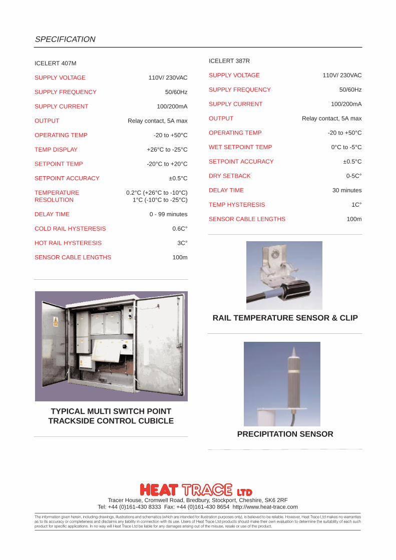
Tracer House, Cromwell Road, Bredbury, Stockport, Cheshire, SK6 2RFTel: +44 (0)161-430 8333 Fax: +44 (0)161-430 8654 http://www.heat-trace.com
The information given herein, including drawings, illustrations and schematics (which are intended for illustration purposes only), is believed to be reliable. However, Heat Trace Ltd makes no warrantiesas to its accuracy or completeness and disclaims any liability in connection with its use. Users of Heat Trace Ltd products should make their own evaluation to determine the suitability of each suchproduct for specific applications. In no way will Heat Trace Ltd be liable for any damages arising out of the misuse, resale or use of the product.
SPECIFICATION
ICELERT 407M
SUPPLY VOLTAGE 110V/ 230VAC
SUPPLY FREQUENCY 50/60Hz
SUPPLY CURRENT 100/200mA
OUTPUT Relay contact, 5A max
OPERATING TEMP -20 to +50°C
TEMP DISPLAY +26°C to -25°C
SETPOINT TEMP -20°C to +20°C
SETPOINT ACCURACY ±0.5°C
TEMPERATURE 0.2°C (+26°C to -10°C)RESOLUTION 1°C (-10°C to -25°C)
DELAY TIME 0 - 99 minutes
COLD RAIL HYSTERESIS 0.6C°
HOT RAIL HYSTERESIS 3C°
SENSOR CABLE LENGTHS 100m
ICELERT 387R
SUPPLY VOLTAGE 110V/ 230VAC
SUPPLY FREQUENCY 50/60Hz
SUPPLY CURRENT 100/200mA
OUTPUT Relay contact, 5A max
OPERATING TEMP -20 to +50°C
WET SETPOINT TEMP 0°C to -5°C
SETPOINT ACCURACY ±0.5°C
DRY SETBACK 0-5C°
DELAY TIME 30 minutes
TEMP HYSTERESIS 1C°
SENSOR CABLE LENGTHS 100m
PRECIPITATION SENSOR
RAIL TEMPERATURE SENSOR & CLIP
TYPICAL MULTI SWITCH POINTTRACKSIDE CONTROL CUBICLE
HOTLINEPreinsulated Tube Bundles
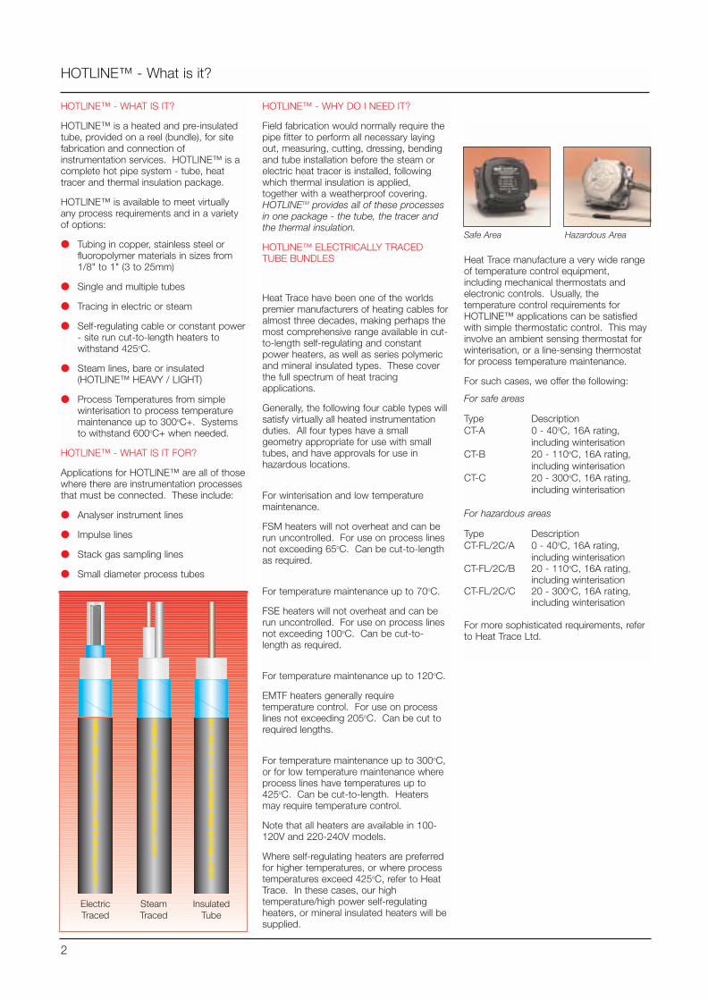
HOTLINE™ - WHAT IS IT?
HOTLINE™ is a heated and pre-insulatedtube, provided on a reel (bundle), for sitefabrication and connection ofinstrumentation services. HOTLINE™ is acomplete hot pipe system - tube, heattracer and thermal insulation package.
HOTLINE™ is available to meet virtuallyany process requirements and in a varietyof options:
Tubing in copper, stainless steel orfluoropolymer materials in sizes from1/8" to 1" (3 to 25mm)
Single and multiple tubes
Tracing in electric or steam
Self-regulating cable or constant power- site run cut-to-length heaters towithstand 425oC.
Steam lines, bare or insulated(HOTLINE™ HEAVY / LIGHT)
Process Temperatures from simplewinterisation to process temperaturemaintenance up to 300oC+. Systemsto withstand 600oC+ when needed.
HOTLINE™ - WHAT IS IT FOR?
Applications for HOTLINE™ are all of thosewhere there are instrumentation processesthat must be connected. These include:
Analyser instrument lines
Impulse lines
Stack gas sampling lines
Small diameter process tubes
HOTLINE™ - What is it?
2
HOTLINE™ - WHY DO I NEED IT?
Field fabrication would normally require thepipe fitter to perform all necessary layingout, measuring, cutting, dressing, bendingand tube installation before the steam orelectric heat tracer is installed, followingwhich thermal insulation is applied,together with a weatherproof covering.HOTLINETM provides all of these processesin one package - the tube, the tracer andthe thermal insulation.
HOTLINE™ ELECTRICALLY TRACEDTUBE BUNDLES
Electric Heating Cables
Heat Trace have been one of the worldspremier manufacturers of heating cables foralmost three decades, making perhaps themost comprehensive range available in cut-to-length self-regulating and constantpower heaters, as well as series polymericand mineral insulated types. These coverthe full spectrum of heat tracingapplications.
Generally, the following four cable types willsatisfy virtually all heated instrumentationduties. All four types have a smallgeometry appropriate for use with smalltubes, and have approvals for use inhazardous locations.
FSM Self-Regulating CablesFor winterisation and low temperaturemaintenance.
FSM heaters will not overheat and can berun uncontrolled. For use on process linesnot exceeding 65oC. Can be cut-to-lengthas required.
FSE Self-Regulating CablesFor temperature maintenance up to 70oC.
FSE heaters will not overheat and can berun uncontrolled. For use on process linesnot exceeding 100oC. Can be cut-to-length as required.
EMTF Constant Power CablesFor temperature maintenance up to 120oC.
EMTF heaters generally requiretemperature control. For use on processlines not exceeding 205oC. Can be cut torequired lengths.
AHT Constant Power CablesFor temperature maintenance up to 300oC,or for low temperature maintenance whereprocess lines have temperatures up to425oC. Can be cut-to-length. Heatersmay require temperature control.
Note that all heaters are available in 100-120V and 220-240V models.
Where self-regulating heaters are preferredfor higher temperatures, or where processtemperatures exceed 425oC, refer to HeatTrace. In these cases, our hightemperature/high power self-regulatingheaters, or mineral insulated heaters will besupplied.
Temperature Control
Heat Trace manufacture a very wide rangeof temperature control equipment,including mechanical thermostats andelectronic controls. Usually, thetemperature control requirements forHOTLINE™ applications can be satisfiedwith simple thermostatic control. This mayinvolve an ambient sensing thermostat forwinterisation, or a line-sensing thermostatfor process temperature maintenance.
For such cases, we offer the following:
For safe areas
Type DescriptionCT-A 0 - 40oC, 16A rating,
including winterisationCT-B 20 - 110oC, 16A rating,
including winterisationCT-C 20 - 300oC, 16A rating,
including winterisation
For hazardous areas
Type DescriptionCT-FL/2C/A 0 - 40oC, 16A rating,
including winterisationCT-FL/2C/B 20 - 110oC, 16A rating,
including winterisationCT-FL/2C/C 20 - 300oC, 16A rating,
including winterisation
For more sophisticated requirements, referto Heat Trace Ltd.
Safe Area Hazardous Area
HE
AT
TR
AC
E S
TE
AM
TR
AC
ED
TU
BIN
G
HE
AH
EAT
T
TR
AT
RA
CE
EL
EC
TR
IC H
EA
CE
EL
EC
TR
IC H
EAT
T
TR
AT
RA
CE
D
CE
D T
UB
ING
TU
BIN
G
HE
AH
EAT
T
TR
AT
RA
CE
ST
EA
M
CE
ST
EA
M T
RA
TR
AC
ED
C
ED
TU
BIN
GT
UB
ING
HE
AT
TR
AC
E S
TE
AM
TR
AC
ED
TU
BIN
G
HE
AH
EAT
T
TR
AT
RA
CE
PR
E-I
NS
UL
AC
E P
RE
-IN
SU
LAT
ED
T
ED
TU
BIN
G C
OP
PE
RT
UB
ING
CO
PP
ER
ElectricTraced
InsulatedTube
SteamTraced
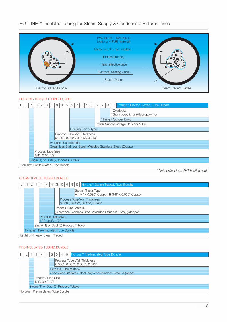
HOTLINE™ Insulated Tubing for Steam Supply & Condensate Returns Lines
3
PVC jacket - 105 Deg C(optionally PUR material)
Glass fibre thermal insulation
Process tube(s)
Heat reflective tape
Electrical heating cable
Steam Tracer
1 3 / 8 0 3 5 1 7 F S E 2 - C T
* Not applicable to AHT heating cable
H L C
1 1 / 4 0 4 9 BH L SL
HOTLINETM Electric Traced, Tube Bundle
HOTLINETM Steam Traced, Tube Bundle
Steam Traced BundleElectric Traced Bundle
1 1 / 4 S 0 4H L 9 HOTLINETM Pre-Insulated Tube Bundle
* Overjacket(T)hermoplastic or (F)luoropolymer
* Tinned Copper Braid
Power Supply Voltage, 115V or 230V
Heating Cable Type
Process Tube Wall Thickness0.030”, 0.032”, 0.035”, 0.049”
Process Tube Material(S)eamless Stainless Steel, (W)elded Stainless Steel, (C)opper
Process Tube Size1/4”, 3/8”, 1/2”
Single (1) or Dual (2) Process Tube(s)
HOTLINETM Pre-Insulated Tube Bundle
Steam Tracer TypeA 1/4” x 0.030” Copper, B 3/8” x 0.032” Copper
Process Tube Wall Thickness0.030”, 0.032”, 0.035”, 0.049”
Process Tube Material(S)eamless Stainless Steel, (W)elded Stainless Steel, (C)opper
Process Tube Size1/4”, 3/8”, 1/2”
Single (1) or Dual (2) Process Tube(s)
HOTLINETM Pre-Insulated Tube Bundle
(L)ight or (H)eavy Steam Traced
Process Tube Wall Thickness0.030”, 0.032”, 0.035”, 0.049”
Process Tube Material(S)eamless Stainless Steel, (W)elded Stainless Steel, (C)opper
Process Tube Size1/4”, 3/8”, 1/2”
Single (1) or Dual (2) Process Tube(s)
HOTLINETM Pre-Insulated Tube Bundle
ELECTRIC TRACED TUBING BUNDLE
STEAM TRACED TUBING BUNDLE
PRE-INSULATED TUBING BUNDLE
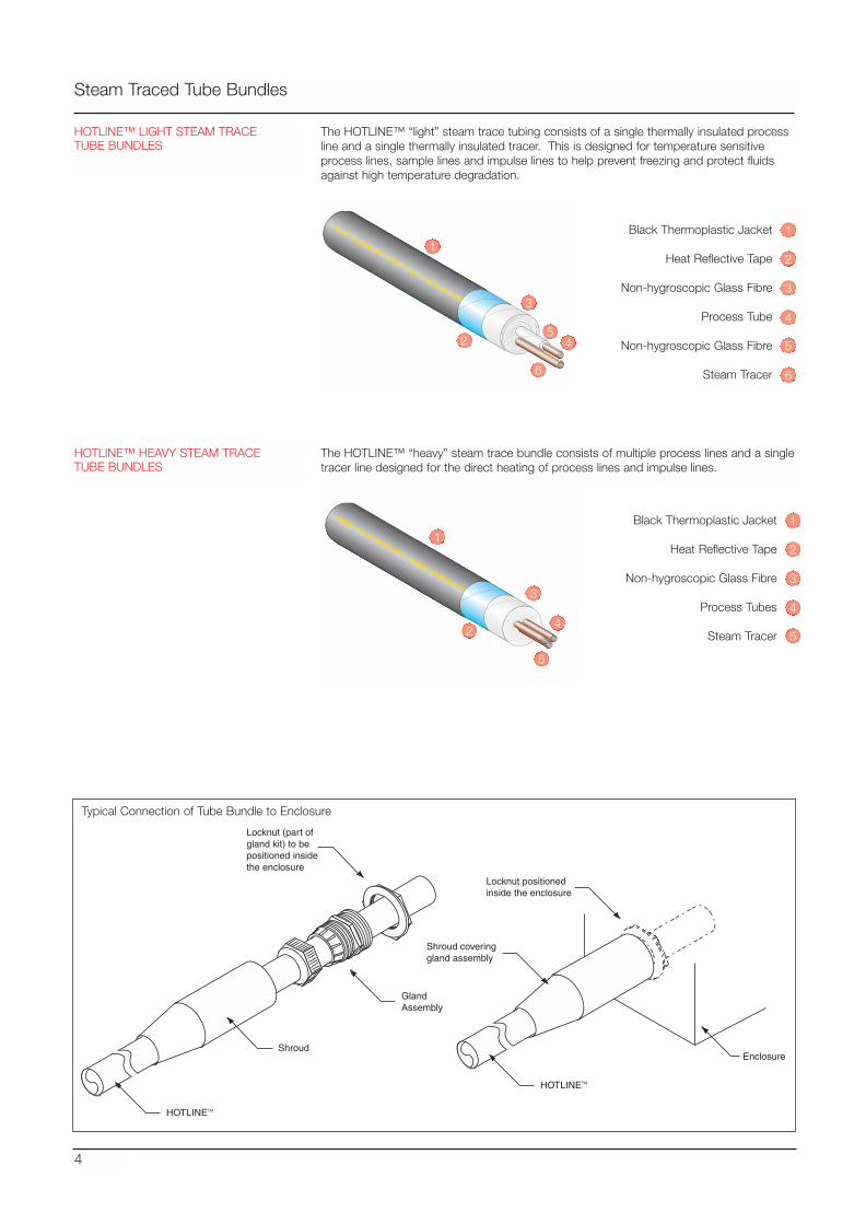
HOTLINE™ HEAVY STEAM TRACETUBE BUNDLES
The HOTLINE™ “heavy” steam trace bundle consists of multiple process lines and a singletracer line designed for the direct heating of process lines and impulse lines.
4
Steam Traced Tube Bundles
HOTLINE™ LIGHT STEAM TRACETUBE BUNDLES
Black Thermoplastic Jacket
Heat Reflective Tape
Non-hygroscopic Glass Fibre
Process Tube
Non-hygroscopic Glass Fibre
Steam Tracer
4
1
2
3
5
6
1
3
4
5
6
2
Black Thermoplastic Jacket
Heat Reflective Tape
Non-hygroscopic Glass Fibre
Process Tubes
Steam Tracer4
1
2
3
1
3
4
5
2
The HOTLINE™ “light” steam trace tubing consists of a single thermally insulated processline and a single thermally insulated tracer. This is designed for temperature sensitiveprocess lines, sample lines and impulse lines to help prevent freezing and protect fluidsagainst high temperature degradation.
5
HOTLINETM
Shroud
GlandAssembly
Locknut (part ofgland kit) to bepositioned insidethe enclosure
Typical Connection of Tube Bundle to Enclosure
HOTLINETM
Shroud coveringgland assembly
Locknut positioned inside the enclosure
Enclosure
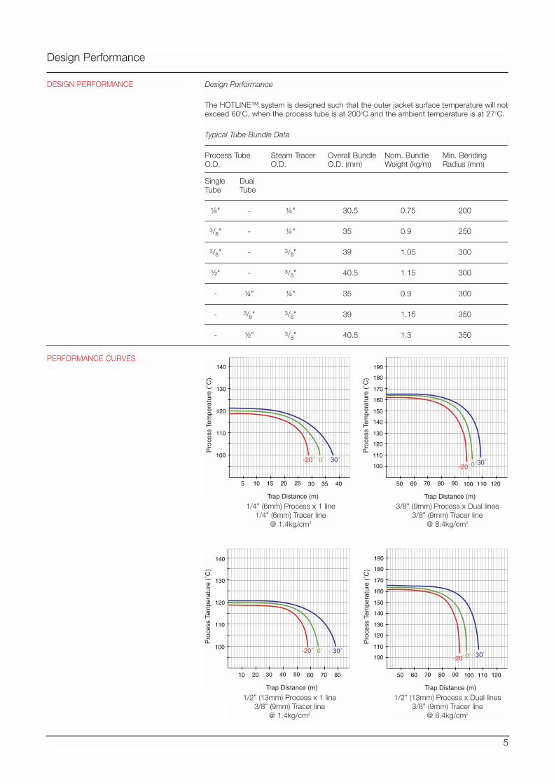
Design Performance
5
Design Performance
The HOTLINE™ system is designed such that the outer jacket surface temperature will notexceed 60oC, when the process tube is at 200oC and the ambient temperature is at 27oC.
Typical Tube Bundle Data
Process Tube Steam Tracer Overall Bundle Nom. Bundle Min. BendingO.D. O.D. O.D. (mm) Weight (kg/m) Radius (mm)
Single DualTube Tube
¼" - ¼" 30.5 0.75 200
3/8" - ¼" 35 0.9 250
3/8" - 3/8" 39 1.05 300
½" - 3/8" 40.5 1.15 300
- ¼" ¼" 35 0.9 300
- 3/8" 3/8" 39 1.15 350
- ½" 3/8" 40.5 1.3 350
140
130
120
110
100
5 10 15 20 25 30 35 40
Pro
cess
Tem
pera
ture
(˚C
)
Trap Distance (m)
30˚-20˚ 0˚
190
180
160
140
120
100
170
150
130
110
50 60 70 80 90 100 110 120
Pro
cess
Tem
pera
ture
(˚C
)
Trap Distance (m)
30˚-20˚0˚
1/4” (6mm) Process x 1 line1/4” (6mm) Tracer line
@ 1.4kg/cm2
3/8” (9mm) Process x Dual lines3/8” (9mm) Tracer line
@ 8.4kg/cm2
140
130
120
110
100
10 20 30 40 50 60 70 80
Pro
cess
Tem
pera
ture
(˚C
)
Trap Distance (m)
30˚-20˚ 0˚
190
180
160
140
120
100
170
150
130
110
50 60 70 80 90 100 110 120
Pro
cess
Tem
pera
ture
(˚C
)
Trap Distance (m)
30˚-20˚0˚
1/2” (13mm) Process x 1 line3/8” (9mm) Tracer line
@ 1.4kg/cm2
1/2” (13mm) Process x Dual lines3/8” (9mm) Tracer line
@ 8.4kg/cm2
PERFORMANCE CURVES
DESIGN PERFORMANCE
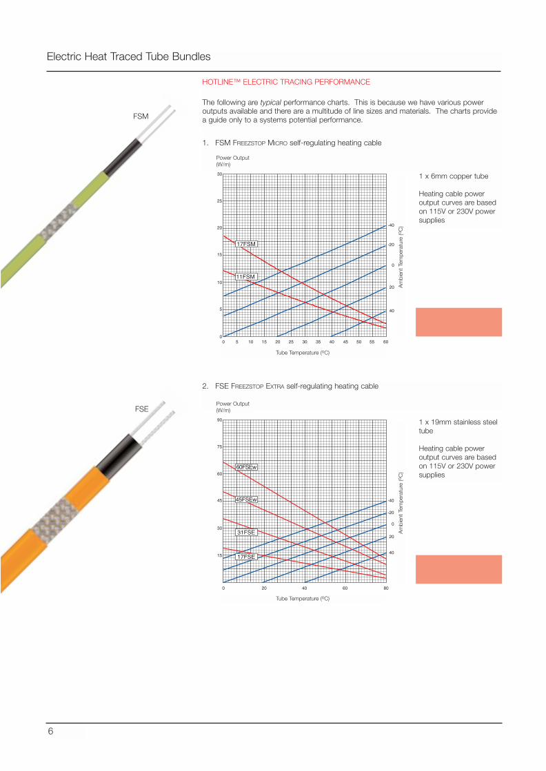
Electric Heat Traced Tube Bundles
HOTLINE™ ELECTRIC TRACING PERFORMANCE
The following are typical performance charts. This is because we have various poweroutputs available and there are a multitude of line sizes and materials. The charts providea guide only to a systems potential performance.
6
1. FSM FREEZSTOP MICRO self-regulating heating cable
FSM
FSE
-40
-20
0
20
40
0 5
5
0
15
10
25
30
20
10 15 20 25 30 35 40 45 6050 55
17FSM
11FSM
-40
-20
0
20
40
0
15
30
45
75
90
60
40 6020 80
45FSEw
60FSEw
31FSE
17FSE
2. FSE FREEZSTOP EXTRA self-regulating heating cable
Am
bien
t Te
mpe
ratu
re (o
C)
1 x 6mm copper tube
Heating cable poweroutput curves are basedon 115V or 230V powersupplies
Tube Temperature (oC)
Power Output(W/m)
Am
bien
t Te
mpe
ratu
re (o
C)
1 x 19mm stainless steeltube
Heating cable poweroutput curves are basedon 115V or 230V powersupplies
Tube Temperature (oC)
Power Output(W/m)
Winterisation and lowtemperaturemaintenance
Process temperaturemaintenance to 70oC
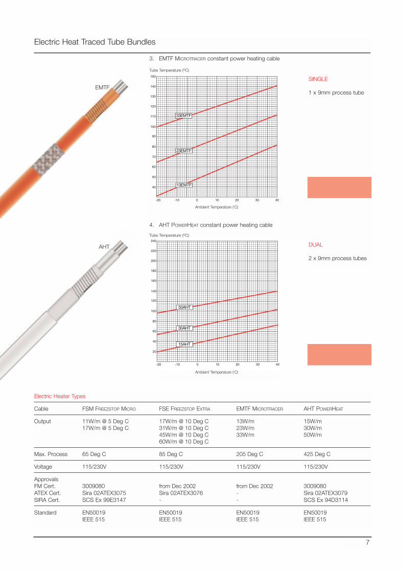
Electric Heat Traced Tube Bundles
7
3. EMTF MICROTRACER constant power heating cable
4. AHT POWERHEAT constant power heating cable
-20
40
50
60
70
80
90
100
120
130
140
150
110
-10 0 10 20 4030
13EMTF
33EMTF
23EMTF
-20
20
40
60
80
100
120
140
180
200
220
240
160
-10 0 10 20 4030
15AHT
50AHT
30AHT
SINGLE
1 x 9mm process tube
Ambient Temperature (oC)
Tube Temperature (oC)
DUAL
2 x 9mm process tubes
Ambient Temperature (oC)
Tube Temperature (oC)
Electric Heater Types
Cable FSM FREEZSTOP MICRO FSE FREEZSTOP EXTRA EMTF MICROTRACER AHT POWERHEAT
Output 11W/m @ 5 Deg C 17W/m @ 10 Deg C 13W/m 15W/m17W/m @ 5 Deg C 31W/m @ 10 Deg C 23W/m 30W/m
45W/m @ 10 Deg C 33W/m 50W/m 60W/m @ 10 Deg C
Max. Process 65 Deg C 85 Deg C 205 Deg C 425 Deg C
Voltage 115/230V 115/230V 115/230V 115/230V
ApprovalsFM Cert. 3009080 from Dec 2002 from Dec 2002 3009080ATEX Cert. Sira 02ATEX3075 Sira 02ATEX3076 - Sira 02ATEX3079SIRA Cert. SCS Ex 99E3147 - - SCS Ex 94D3114
Standard EN50019 EN50019 EN50019 EN50019IEEE 515 IEEE 515 IEEE 515 IEEE 515
EMTF
AHT
Process temperaturemaintenance to 120oC
Process temperaturemaintenance to 300oC
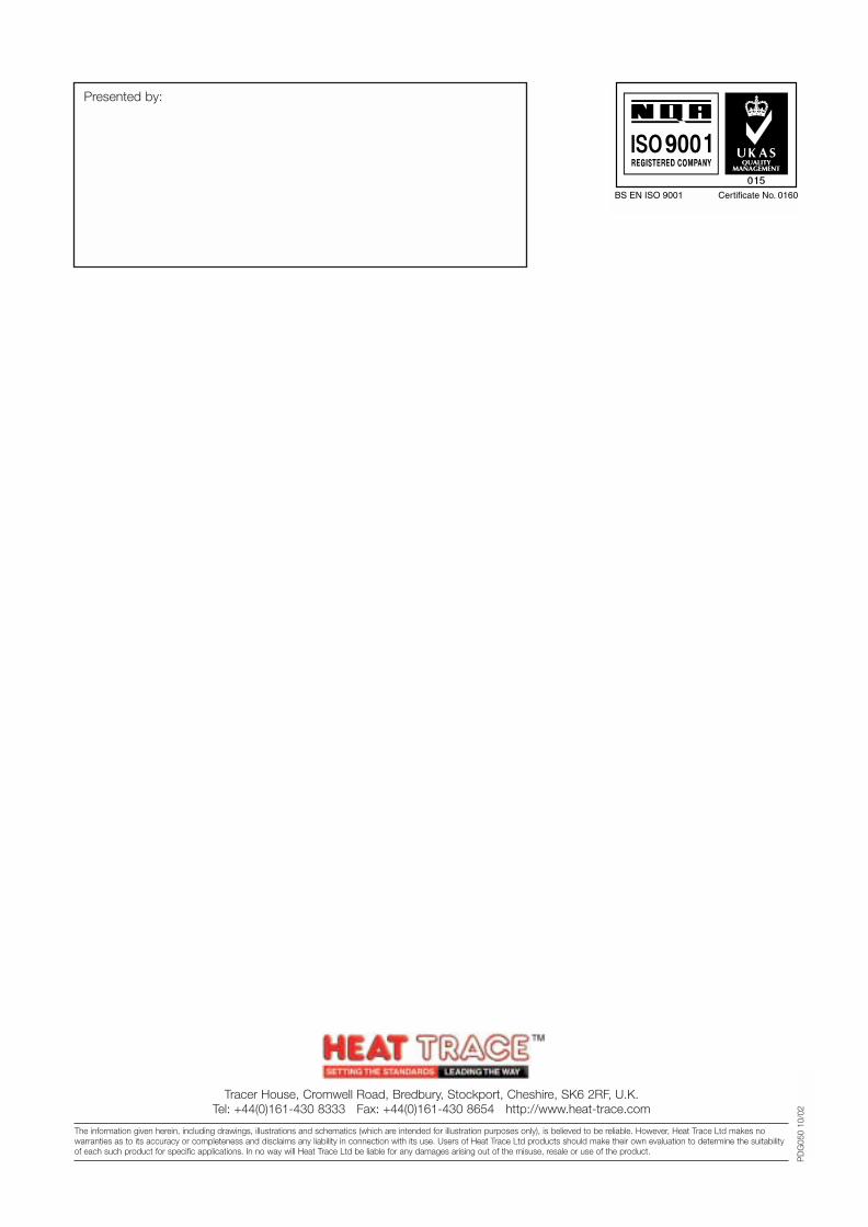
Tracer House, Cromwell Road, Bredbury, Stockport, Cheshire, SK6 2RF, U.K.Tel: +44(0)161-430 8333 Fax: +44(0)161-430 8654 http://www.heat-trace.com
The information given herein, including drawings, illustrations and schematics (which are intended for illustration purposes only), is believed to be reliable. However, Heat Trace Ltd makes nowarranties as to its accuracy or completeness and disclaims any liability in connection with its use. Users of Heat Trace Ltd products should make their own evaluation to determine the suitabilityof each such product for specific applications. In no way will Heat Trace Ltd be liable for any damages arising out of the misuse, resale or use of the product.
PD
G05
0 10
/02
Presented by:
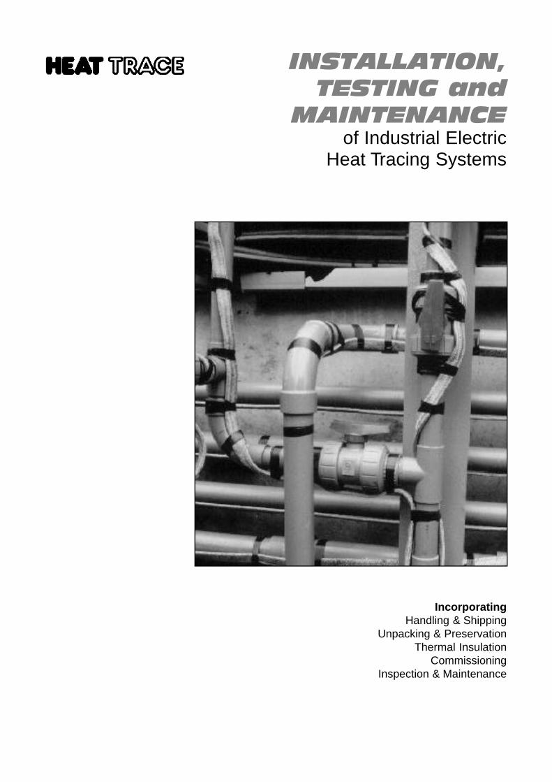
INSTALLATION,TESTING and
MAINTENANCEof Industrial Electric
Heat Tracing Systems
IncorporatingHandling & Shipping
Unpacking & PreservationThermal Insulation
CommissioningInspection & Maintenance
Section Page
Handling & Shipping G:4ESH Ancillaries, Field Mounted Controllers,Control and Distribution Panels,Hook-up Cabling, Cabling Ancillaries,Reception & Storage, COSHH Requirements
Unpacking & Preservation G:5Transit to Job Site, Preservation, Storage
Installation G:5 - 9Hazardous Areas, Tips for the installer, Pre-Installation,Installation, Site specific, Installation Procedure,Electrical Supply Points, Spiral Pitch, Cable Installtion,Cable Fixings, Flanges, Valves, Cable Terminations,Tee Branches, Plastic Pipework, Sensor Location,Electrical Connections, Earthing / Bonding,Distribution, control and monitoring panels
Testing G:11Special Tools
Thermal Insulation G:12Purpose, System, Properties, Selection of Material, Installation
Commissioning G:13
Inspection & Maintenance Testing G:14-15Operating conditions,Tests on local distribution and control panels,Field mounted components, Heater tests,Insulation resistance testing (all heater styles),Load resistance (constant wattage heaters),Single phase, Three phase,Load resistance (self-regulating heaters),Completion, Repair & Replacement
Installation Test Certificate (QC48) G:16
Other forms and documents that might be more relevant to a specificapplication are available from Heat Trace Ltd Head Office.
Examples of alternative forms and documents are shown in StandardsBS6361 and IEEE Std.515
S E C T I O N GI N S T A L L A T I O N , T E S T I N G & M A I N T E N A N C E
G:3
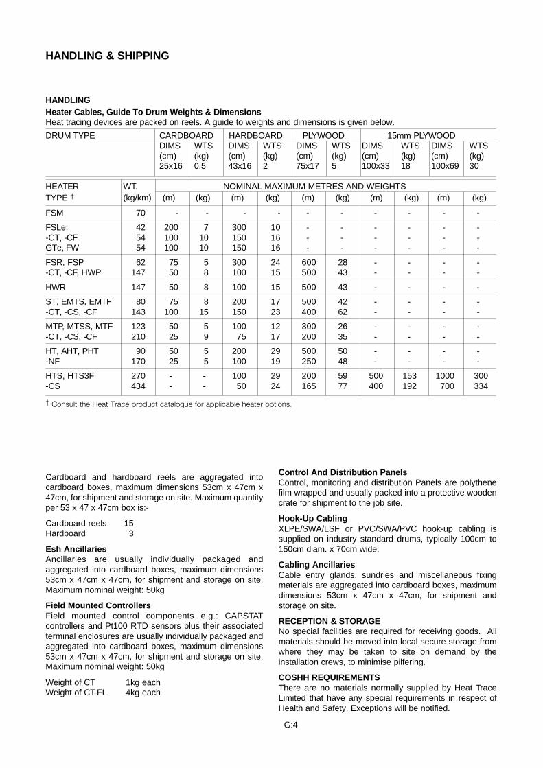
HANDLING & SHIPPING
HANDLING
Cardboard and hardboard reels are aggregated intocardboard boxes, maximum dimensions 53cm x 47cm x47cm, for shipment and storage on site. Maximum quantityper 53 x 47 x 47cm box is:-
Cardboard reels 15Hardboard 3
Esh AncillariesAncillaries are usually individually packaged andaggregated into cardboard boxes, maximum dimensions53cm x 47cm x 47cm, for shipment and storage on site.Maximum nominal weight: 50kg
Field Mounted ControllersField mounted control components e.g.: CAPSTATcontrollers and Pt100 RTD sensors plus their associatedterminal enclosures are usually individually packaged andaggregated into cardboard boxes, maximum dimensions53cm x 47cm x 47cm, for shipment and storage on site.Maximum nominal weight: 50kg
Weight of CT 1kg eachWeight of CT-FL 4kg each
Heater Cables, Guide To Drum Weights & DimensionsHeat tracing devices are packed on reels. A guide to weights and dimensions is given below.
DRUM TYPE CARDBOARD HARDBOARD PLYWOOD 15mm PLYWOODDIMS WTS DIMS WTS DIMS WTS DIMS WTS DIMS WTS(cm) (kg) (cm) (kg) (cm) (kg) (cm) (kg) (cm) (kg)25x16 0.5 43x16 2 75x17 5 100x33 18 100x69 30
HEATER WT. NOMINAL MAXIMUM METRES AND WEIGHTSTYPE † (kg/km) (m) (kg) (m) (kg) (m) (kg) (m) (kg) (m) (kg)
FSM 70 - - - - - - - - - -
FSLe, 42 200 7 300 10 - - - - - --CT, -CF 54 100 10 150 16 - - - - - -GTe, FW 54 100 10 150 16 - - - - - -
FSR, FSP 62 75 5 300 24 600 28 - - - --CT, -CF, HWP 147 50 8 100 15 500 43 - - - -
HWR 147 50 8 100 15 500 43 - - - -
ST, EMTS, EMTF 80 75 8 200 17 500 42 - - - --CT, -CS, -CF 143 100 15 150 23 400 62 - - - -
MTP, MTSS, MTF 123 50 5 100 12 300 26 - - - --CT, -CS, -CF 210 25 9 75 17 200 35 - - - -
HT, AHT, PHT 90 50 5 200 29 500 50 - - - --NF 170 25 5 100 19 250 48 - - - -
HTS, HTS3F 270 - - 100 29 200 59 500 153 1000 300-CS 434 - - 50 24 165 77 400 192 700 334
† Consult the Heat Trace product catalogue for applicable heater options.
Control And Distribution PanelsControl, monitoring and distribution Panels are polythenefilm wrapped and usually packed into a protective woodencrate for shipment to the job site.
Hook-Up CablingXLPE/SWA/LSF or PVC/SWA/PVC hook-up cabling issupplied on industry standard drums, typically 100cm to150cm diam. x 70cm wide.
Cabling AncillariesCable entry glands, sundries and miscellaneous fixingmaterials are aggregated into cardboard boxes, maximumdimensions 53cm x 47cm x 47cm, for shipment andstorage on site.
RECEPTION & STORAGENo special facilities are required for receiving goods. Allmaterials should be moved into local secure storage fromwhere they may be taken to site on demand by theinstallation crews, to minimise pilfering.
COSHH REQUIREMENTSThere are no materials normally supplied by Heat TraceLimited that have any special requirements in respect ofHealth and Safety. Exceptions will be notified.
G:4
UNPACKING & PRESERVATION
UNPACKING
We recommend that users keep materials in localsecure storage within the original packaging untilneeded at the jobsite. Materials may then be unpackedimmediately prior to use. Packaging materials shouldbe taken to the designated disposal point and not beleft lying around the site.
TRANSIT TO JOBSITE
No special equipment will normally be required. Heattracing devices and ancillaries are usually carried byhand to the point of usage. Local control anddistribution panels will be moved and handleddepending upon their weight, like any other controlpanel or distribution board.
Heat tracing units should be kept wrapped on theirdelivery drums or reels until needed at the work site.They should not be stacked more than 3 high. Keepclear of sharp objects, welding operations, or any otheractivity which puts the outer jacket of a flexible heaterat risk from mechanical damage.
Manoeuvre control and distribution panels carefully intotheir final position taking great care not to scratch orotherwise damage the paint finish, viewing windows,handles or other exposed parts.
PRESERVATION
No special preservation regime need be imposed. Theoriginal packaging if kept dry and intact will provesufficient.
STORAGE
Store in clean and dry conditions unless the equipmentclearly has been packed for sea freight as deck cargoe.g.: polythene wrapped with desiccant and containedwithin a solid wooden case when it may be stored inopen sided but covered areas. Termination kitscontaining silicone rubber sealant (RTV) should bestored at temperatures below 25°C (77°F) or consumedwithin 6 months of shipment.
INSTALLATION
GENERAL
Installation of electric surface heating devices shouldbe in accordance with BS7671 (IEE WiringRegulations), BS6351:Part 3: Code of Practice for theInstallation, Testing and Maintenance of ElectricSurface Heating systems, or American StandardsANSI:IEEE515 and 515.1: Testing, Design, Installationand Maintenance of electrical resistance Heat Tracing,whichever is the most convenient to local practice,supplemented by any site specific instructions).
Only suitably trained personnel should be employed inthe installation and testing of electric heat tracingsystems. A trained supervisor should be in attendanceat all stages of the work, particularly for installation inhazardous areas.
Refer to the appropriate product data sheet andtermination instructions for additional information.
HAZARDOUS AREA
Special considerations pertain to installations inpotentially explosive atmospheres, eg. In addition tothe requirements of the DIN VDE 0100 series, DINVDE 0721 Part 1 and DIN VDE 0721 Part 2A3 shallalso be complied with where used in industry. Furtherdetail may be found in the referenced Standards orfrom the Heat Trace Contracts Department.
TIPS FOR THE INSTALLER
A. Pre-Installation
Before starting the installation phase:
Check that you have adequate sketches or drawings todefine the scope of the heat tracing work and thecorrect type, style and voltage of the heaters.
Walk the system and plan your routes.
Measure out the lengths of pipework to be tracedand/or check the dimensions of tanks and vessels toensure that they are those as shown on the drawings.If not, then contact the supplier or design office forfurther instructions before proceeding.
Ensure that the surfaces to be heated are fully tested,free for use and free from any sharp edges, weldsplatter, cement splashes or other substances whichcould damage the sheath of the heaters.
Check with the client to confirm the arrangementsmade for applying the thermal insulation. This workmust be co-ordinated to minimise the risks ofmechanical damage to the heaters whilst the surfacesare open and unprotected by lagging.
Fix and mark the position of all circuit supply pointsand thermostat sensor locations, paying particularattention to the location of any over-temperaturedevices in the system.
G:5
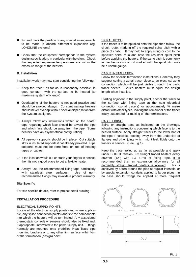
SPIRAL PITCHIf the tracer is to be spiralled onto the pipe then follow thecircuit route, marking off the required spiral pitch with apiece of chalk. It may help to apply string or cord to thespecified spiral ratio and note the resultant spiral pitchbefore applying the heaters. If the same pitch is commonlyin use then a stick or rod marked with the spiral pitch maybe a useful gauge.
CABLE INSTALLATIONFollow the specific termination instructions. Generally theysuggest cutting a zonal tracer close to an electrical zoneconnection which will be just visible through the basictracer sheath. Series heaters must equal the designlength when installed.
Starting adjacent to the supply point, anchor the tracer tothe surface with fixing tape at the next electricalconnection (zonal tracers) or approximately ¾ metredistant with other types, leaving the remainder of the tracerfreely suspended for making off the terminations.
CABLE FIXINGSpiral or straight trace as indicated on the drawings,following any instructions concerning which face is to theheated surface. Apply straight tracers to the lower half ofthe pipe if possible, keeping away from the underside offlanges and other joints which might leak fluids onto thetracers in service. (See Fig 1).
Keep the tracer rolled up as far as possible and applyunder SLIGHT tension. Fix straight traced heaters every300mm (12”) with 1½ turns of fixing tape. It isrecommended that an expansion allowance for allnominally straight traced heaters is allowed. This isachieved by a turn around the pipe at regular intervals, orby special expansion conduits applied to larger pipes. Inno case should fixings be applied at more frequent
Fig 1
Fix and mark the position of any special arrangementsto be made to absorb differential expansion (eg.LONGLINE systems)
Check that the equipment corresponds to the systemdesign specification, in particular with the client. Checkthat expected exposure temperatures are within theexposure range of the heaters.
B. Installation
Installation work may now start considering the following:-
Keep the tracer, as far as is reasonably possible, ingood contact with the surface to be heated (tomaximise system efficiency.)
Overlapping of the heaters is not good practice andshould be avoided always. Constant wattage heatersshould never overlap without special dispensation fromthe System Designer.
Always follow any instructions written on the heatertape regarding which face should be toward the pipeand which face should be away from the pipe. (Someheaters have an asymmetrical configuration).
All pipework supports should be in place. Cut suitableslots in insulated supports if not already provided. Pipesupports must not be retro-fitted on top of heatingtapes or cables.
If the location would cut or crush your fingers in servicethen its not a good place to put a flexible heater.
Always use the recommended fixing tape particularlywith stainless steel surfaces. Use of non-recommended fixings may invalidate product warranty.
Site Specific
For site specific details, refer to project detail drawing.
INSTALLATION PROCEDURE
ELECTRICAL SUPPLY POINTSLocate all the electrical supply points (and where applica-ble, any splice connection points) and site the componentsinto which the heaters will be terminated. Any associatedthermostatic controls or sensors should also be fixed and,if appropriate, interwired to the power supply unit. Fittingsnormally are mounted onto predrilled Heat Trace pipemounting brackets or to any other firm surface within ½mof the termination (design) point.
G:6
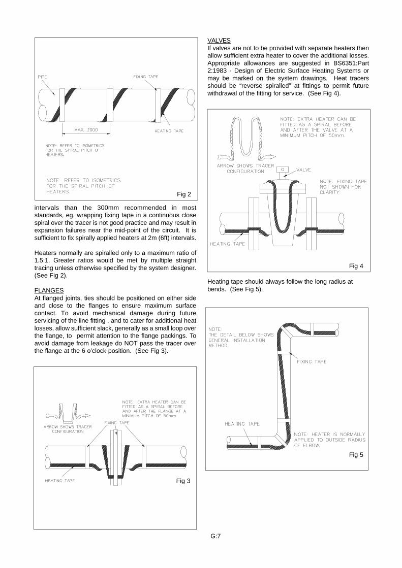
intervals than the 300mm recommended in moststandards, eg. wrapping fixing tape in a continuous closespiral over the tracer is not good practice and may result inexpansion failures near the mid-point of the circuit. It issufficient to fix spirally applied heaters at 2m (6ft) intervals.
Heaters normally are spiralled only to a maximum ratio of1.5:1. Greater ratios would be met by multiple straighttracing unless otherwise specified by the system designer.(See Fig 2).
FLANGESAt flanged joints, ties should be positioned on either sideand close to the flanges to ensure maximum surfacecontact. To avoid mechanical damage during futureservicing of the line fitting , and to cater for additional heatlosses, allow sufficient slack, generally as a small loop overthe flange, to permit attention to the flange packings. Toavoid damage from leakage do NOT pass the tracer overthe flange at the 6 o’clock position. (See Fig 3).
VALVESIf valves are not to be provided with separate heaters thenallow sufficient extra heater to cover the additional losses.Appropriate allowances are suggested in BS6351:Part2:1983 - Design of Electric Surface Heating Systems ormay be marked on the system drawings. Heat tracersshould be “reverse spiralled” at fittings to permit futurewithdrawal of the fitting for service. (See Fig 4).
Heating tape should always follow the long radius atbends. (See Fig 5).
Fig 2
Fig 3
Fig 4
Fig 5
G:7
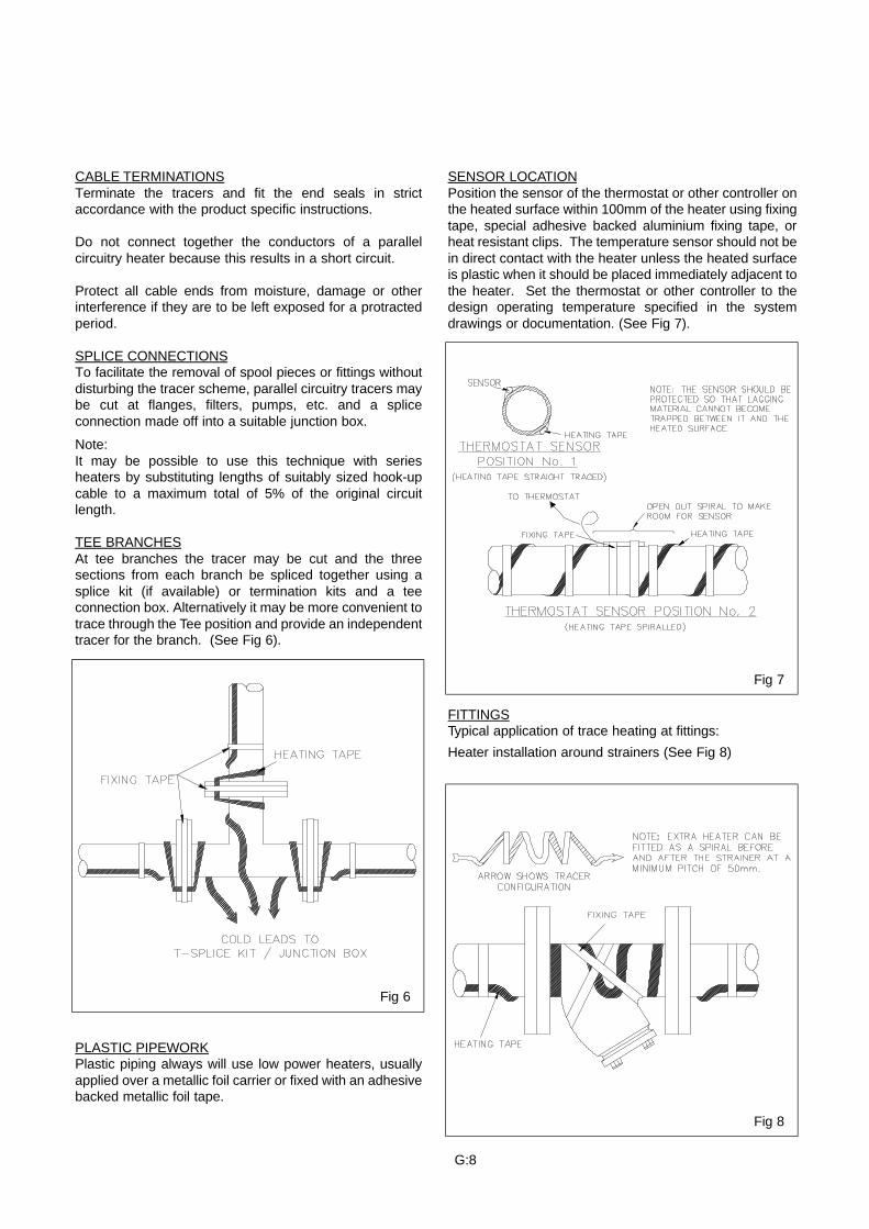
CABLE TERMINATIONSTerminate the tracers and fit the end seals in strictaccordance with the product specific instructions.
Do not connect together the conductors of a parallelcircuitry heater because this results in a short circuit.
Protect all cable ends from moisture, damage or otherinterference if they are to be left exposed for a protractedperiod.
SPLICE CONNECTIONSTo facilitate the removal of spool pieces or fittings withoutdisturbing the tracer scheme, parallel circuitry tracers maybe cut at flanges, filters, pumps, etc. and a spliceconnection made off into a suitable junction box.
Note:It may be possible to use this technique with seriesheaters by substituting lengths of suitably sized hook-upcable to a maximum total of 5% of the original circuitlength.
TEE BRANCHESAt tee branches the tracer may be cut and the threesections from each branch be spliced together using asplice kit (if available) or termination kits and a teeconnection box. Alternatively it may be more convenient totrace through the Tee position and provide an independenttracer for the branch. (See Fig 6).
PLASTIC PIPEWORKPlastic piping always will use low power heaters, usuallyapplied over a metallic foil carrier or fixed with an adhesivebacked metallic foil tape.
SENSOR LOCATIONPosition the sensor of the thermostat or other controller onthe heated surface within 100mm of the heater using fixingtape, special adhesive backed aluminium fixing tape, orheat resistant clips. The temperature sensor should not bein direct contact with the heater unless the heated surfaceis plastic when it should be placed immediately adjacent tothe heater. Set the thermostat or other controller to thedesign operating temperature specified in the systemdrawings or documentation. (See Fig 7).
FITTINGSTypical application of trace heating at fittings:
Heater installation around strainers (See Fig 8)
Fig 6
Fig 7
Fig 8
G:8
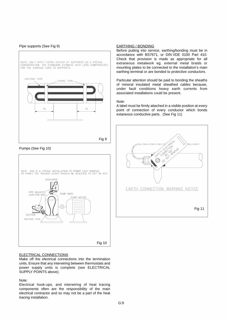
Pipe supports (See Fig 9)
Pumps (See Fig 10)
ELECTRICAL CONNECTIONSMake off the electrical connections into the terminationunits. Ensure that any interwiring between thermostats andpower supply units is complete (see ELECTRICALSUPPLY POINTS above).
Note: Electrical hook-ups, and interwiring of heat tracingcomponents often are the responsibility of the mainelectrical contractor and so may not be a part of the heattracing installation.
EARTHING / BONDINGBefore putting into service, earthing/bonding must be inaccordance with BS7671, or DIN VDE 0100 Part 410.Check that provision is made as appropriate for allextraneous metalwork eg. external metal braids ormounting plates to be connected to the installation’s mainearthing terminal or are bonded to protective conductors.
Particular attention should be paid to bonding the sheathsof mineral insulated metal sheathed cables because,under fault conditions heavy earth currents fromassociated installations could be present.
Note:A label must be firmly attached in a visible position at everypoint of connection of every conductor which bondsextaneous conductive parts. (See Fig 11)
Fig 9
Fig 10
Fig 11
G:9
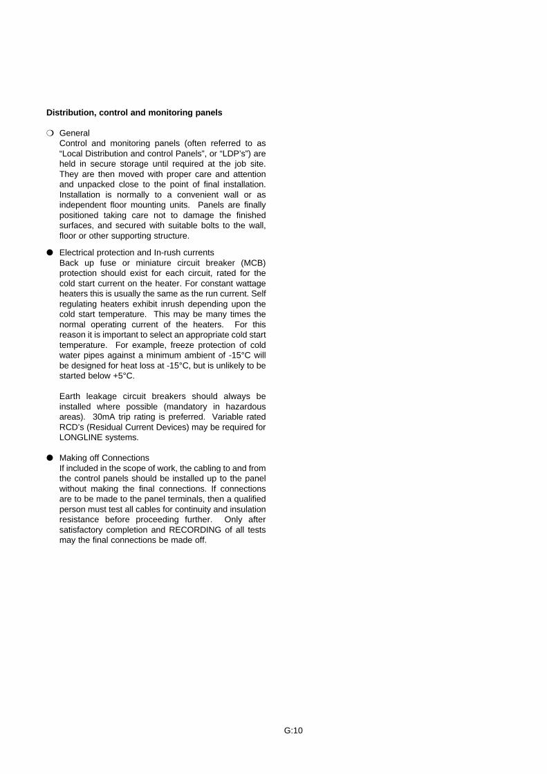
Distribution, control and monitoring panels
GeneralControl and monitoring panels (often referred to as“Local Distribution and control Panels”, or “LDP’s”) areheld in secure storage until required at the job site.They are then moved with proper care and attentionand unpacked close to the point of final installation.Installation is normally to a convenient wall or asindependent floor mounting units. Panels are finallypositioned taking care not to damage the finishedsurfaces, and secured with suitable bolts to the wall,floor or other supporting structure.
Electrical protection and In-rush currentsBack up fuse or miniature circuit breaker (MCB)protection should exist for each circuit, rated for thecold start current on the heater. For constant wattageheaters this is usually the same as the run current. Selfregulating heaters exhibit inrush depending upon thecold start temperature. This may be many times thenormal operating current of the heaters. For thisreason it is important to select an appropriate cold starttemperature. For example, freeze protection of coldwater pipes against a minimum ambient of -15°C willbe designed for heat loss at -15°C, but is unlikely to bestarted below +5°C.
Earth leakage circuit breakers should always beinstalled where possible (mandatory in hazardousareas). 30mA trip rating is preferred. Variable ratedRCD’s (Residual Current Devices) may be required forLONGLINE systems.
Making off ConnectionsIf included in the scope of work, the cabling to and fromthe control panels should be installed up to the panelwithout making the final connections. If connectionsare to be made to the panel terminals, then a qualifiedperson must test all cables for continuity and insulationresistance before proceeding further. Only aftersatisfactory completion and RECORDING of all testsmay the final connections be made off.
G:10
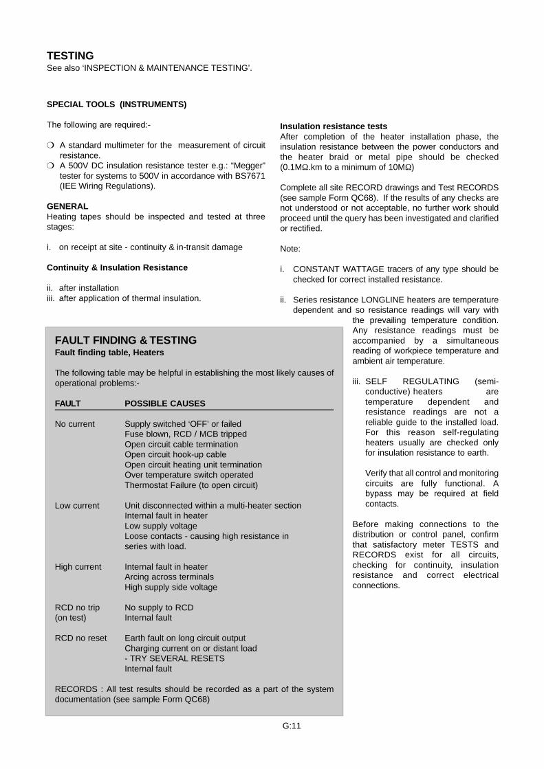
Insulation resistance testsAfter completion of the heater installation phase, theinsulation resistance between the power conductors andthe heater braid or metal pipe should be checked(0.1MΩ.km to a minimum of 10MΩ)
Complete all site RECORD drawings and Test RECORDS(see sample Form QC68). If the results of any checks arenot understood or not acceptable, no further work shouldproceed until the query has been investigated and clarifiedor rectified.
Note:
i. CONSTANT WATTAGE tracers of any type should bechecked for correct installed resistance.
ii. Series resistance LONGLINE heaters are temperaturedependent and so resistance readings will vary with
the prevailing temperature condition.Any resistance readings must beaccompanied by a simultaneousreading of workpiece temperature andambient air temperature.
iii. SELF REGULATING (semi-conductive) heaters aretemperature dependent andresistance readings are not areliable guide to the installed load.For this reason self-regulatingheaters usually are checked onlyfor insulation resistance to earth.
Verify that all control and monitoringcircuits are fully functional. Abypass may be required at fieldcontacts.
Before making connections to thedistribution or control panel, confirmthat satisfactory meter TESTS andRECORDS exist for all circuits,checking for continuity, insulationresistance and correct electricalconnections.
TESTINGSee also ‘INSPECTION & MAINTENANCE TESTING’.
SPECIAL TOOLS (INSTRUMENTS)
The following are required:-
A standard multimeter for the measurement of circuitresistance.
A 500V DC insulation resistance tester e.g.: “Megger”tester for systems to 500V in accordance with BS7671(IEE Wiring Regulations).
GENERALHeating tapes should be inspected and tested at threestages:
i. on receipt at site - continuity & in-transit damage
Continuity & Insulation Resistance
ii. after installationiii. after application of thermal insulation.
FAULT FINDING & TESTINGFault finding table, Heaters
The following table may be helpful in establishing the most likely causes ofoperational problems:-
FAULT POSSIBLE CAUSES
No current Supply switched ‘OFF’ or failedFuse blown, RCD / MCB trippedOpen circuit cable terminationOpen circuit hook-up cableOpen circuit heating unit terminationOver temperature switch operatedThermostat Failure (to open circuit)
Low current Unit disconnected within a multi-heater sectionInternal fault in heaterLow supply voltageLoose contacts - causing high resistance inseries with load.
High current Internal fault in heaterArcing across terminalsHigh supply side voltage
RCD no trip No supply to RCD(on test) Internal fault
RCD no reset Earth fault on long circuit outputCharging current on or distant load- TRY SEVERAL RESETSInternal fault
RECORDS : All test results should be recorded as a part of the systemdocumentation (see sample Form QC68)
G:11
THERMAL INSULATION
PURPOSE:Dry and efficient thermal insulation is fundamental to anyheat tracing scheme. Heat tracing only makes good thelosses from the thermal insulation i.e: it makes the lagging100% efficient.
The thermal insulation system has a quadruple function:-
1) reduction of heat loss to an acceptable economic level2) reducing “touch” temperatures to a safe level3) providing a stable and predictable rate of heat loss that
can be calculated and replaced by electric heat tracing.4) providing mechanical protection for the heating
devices.
SYSTEM:The thermal insulation system comprises two or morelayers:-
1) the thermally insulating material over the heaters2) a vapour barrier over the lagging material3) an outer weatherproofing or abrasion resistant layer
Layers 2) and 3) may be combined.
PROPERTIES:The use of thermally insulating materials on above groundpipes and vessels is embraced by British StandardBS5422:1990 with underground systems being covered byBS4508:1977. The content of these Standards is appliedto Heat Trace Ltd software used in the design of ElectricSurface Heating Systems to BS6351:1983:Part 2,ANSI:IEEE515 and other National or internationalStandards.
SELECTION OF MATERIALThermal insulation must be selected to withstand themaximum surface temperature of the heater which often ishigher than the maximum process temperature. Particularcare is needed in the use of foamed plastic insultants.
INSTALLATION
General
To minimise the risks of damage to heaters, suitablethermal insulation should be fitted as quickly aspossible after completion and testing of each electricalheat tracing circuit. If the thermal insulation workcannot be completed within the working day then wellfixed temporary cover and protection should be appliedto the heating components
Before installation of the thermal insulation materialrestarts, electrical checks should confirm that nodamage has occurred.
Code of PracticeThe installation of the thermal insulation will be inaccordance with Code of Practice BS5970:1982 or otherrelevant Standards.
MARKING BS6351:Part 3 requires “Caution - Electric Traced”
labels to be fitted at a maximum of 6m intervals.
The location of any components concealed beneaththe insulation should be marked on the outer cladding.
Site RECORDS Check and RECORD that the thermal insulation
material is suitable for the hot face temperaturesconcerned and is to the designed thickness.
Recheck and RECORD the heater circuits forcontinuity and insulation resistance after the thermalinsulation has been completed and confirm that thetemperature sensors are still firm, in the right place andthat electrical connections are still valid.
CAUTION: IF ANY WORK IS UNDERTAKEN WHICHINVOLVES THE REMOVAL OF THERMAL INSULATION -ESPECIALLY REMOVABLE FLANGE AND VALVEBOXES - THE GREATEST POSSIBLE CARE MUST BEEXERCISED. METALLIC CLADDING CAN VERY EASILYCUT OR TEAR THE OUTER INSULATION OF ANYFLEXIBLE HEATING TAPE OR CABLE. NO SHARPMETALLIC EDGE SHOULD BE ALLOWED TO COMEINTO CONTACT WITH THE HEATERS AT ANY TIME.
Protecting Cable EntriesHeat Trace Ltd provide a number of accessories tominimise the possibility of damage to heating tapes andcables when passing through the thickness of thermalinsulation. These range from DESTU mountings forFREEZSTOP products, to LEK/U universal lagging entrykits - see product data sheets.
G:12
COMMISSIONING
Commissioning usually is limited to ensuring the accuracyof site records, the electrical safety of the heatinginstallation and any control or distribution package.Provision of a mains supply, energisation and neat provingruns usually lie outside the scope of the heat tracingcontract.
For site specific details refer to the project detaildrawings.
Ensure that all drawings and test certificates (see HTLsample Form QC68) are to hand.
Ensure that the heated surface, pipe, tank or vessel, isproperly connected to the installation’s main earthingterminal or is bonded to protective conductors whichwill be at or near earth potential under fault conditions,using a conductor sized as the main earth conductor toa minimum of 4mm² cross sectional area.
If not already completed or if several days haveelapsed since the RECORDS were entered, recheckand RECORD the heater circuits at the point ofelectrical supply for continuity and insulation resistancefollowing installation of thermal insulation. Check thatjunction boxes are free of water and lids secured.
Confirm that the temperature sensors are still firm, inthe right place and that electrical connections are stillvalid.
Check and RECORD that temperature control(thermostat) units are fully functional and that settingsare correct and accord with the design drawings. Forfrost protection duties it is usual to control several or allcircuits from an air temperature sensing thermostat setat +6°C (43°F).
Check and RECORD that the thermal insulationmaterial is suitable for the hot face temperaturesconcerned and is to the designed thickness.
Fit warning labels in prominent positions to the outsideof the thermal insulation covering at intervals notexceeding 6 metres (20 feet) to indicate the presenceof HEAT TRACE flexible electrical heaters beneath thesurface.
Check the correct operation of any circuit healthmonitoring devices.
Check that all lamps and indicators are functioning andassociated with the correct heater circuit.
Check and RECORD that the back up fuse or MCBprotection is correctly rated and the lowest possiblesize consistent with the circuit characteristics. Whereresidual current devices (RCD’s) are employed, test forcorrect operation and that Warning Notices are inplace.
If part of the heat tracing contract, check that all powerand control cabling is correctly sized, in the rightsequence and in good order.
Complete all permanent tagging, labelling andidentification e.g. heater power connection labels,thermostat number and set point, caution and warninglabels.
ALL RESULTS SHOULD BE RECORDED TO FORMPART OF THE SYSTEM DOCUMENTATION.
A CERTIFICATE OF COMPLETION should beissued upon satisfactory completion of thecommissioning procedure.
G:13
INSPECTION & MAINTENANCE TESTING
GENERALRoutine visual inspection for damage or defects in thethermal insulation system or its weather barrier inspectionis recommended. If damage or defects are found, remedialwork should be put in hand after inspection of theassociated electrical circuit.
Periodic checks should be carried out at least once a year.For frost protection systems this work is convenientlyscheduled in the late summer. More frequent and/or moredetailed inspection may be necessary, depending on thecriticality of the heating system to successful plantoperations, in corrosive or other hostile environments orwhere there is a high risk of mechanical damage.
“As Installed” drawings and test certificates should be tohand during the following checks:-
OPERATING CONDITIONS Ensure that the maximum service temperature is within
that permitted for the heater tape or cable and anyassociated controllers. EXCEEDING THIS LIMIT MAYRESULT IN PERMANENT DAMAGE.
The thermal insulation must be complete and dry if thecorrect temperature is to be maintained.
TESTS ON LOCAL DISTRIBUTION AND CONTROLPANELS
Isolate the incoming supply. Check and RECORD thefollowing:-
Correct operation of RCD’s and the presence ofstatutory Warning Notices.
Correct operation of MCB’s
Correct settings and operation of all temperatureresponsive controllers.
Correct operation of any Circuit health monitoringdevices.
All lamps and indicators in working order.
The correct operation of individual HTL control andmonitoring devices may be assured by following specificSite Setting Up Procedures.
FIELD MOUNTED COMPONENTS...
Temperature sensors are securely affixed.
Junction boxes are free from ingress of water and withterminals secure and in good condition.
Power and control cabling is in good order.
Thermal insulation is clean, sound and dry.
HEATER TESTSDisconnect heater circuits in the distribution board orpanel.
Refer to the TEST SHEETS (see HTL sample FormQC68). See also ‘TESTING’.
Test 1 - Earth Faults at the distribution or control panel
Insulation Resistance Testing, all Heater Styles
Use a 500V DC insulation resistance tester (“Megger”)between live and/or neutral connection and earth for eachheat tracing sector. A steady reading of 0.1MΩ.km(typically around 200 Megohms should be attained. Eachsection of heating tape should be tested individually.
Typical causes of low insulation resistance readingsinclude ...
Cold lead-ins to heaters damaged in the junction box orwhere the heater passes through metallic cladding tothe thermal insulation.
Water inside a terminal box.
Test 2 - Load Current Faults
A. Load Resistance, Constant Wattage Heaters
Use a multimeter or similar digital ohmmeter and crossrefer to Test Sheet Data.
A.1 Single Phase System, Parallel Circuitry
Test between live and neutral connections of the heatercircuit. Compare this reading of total load resistancewith that obtained at commissioning and shown on theTest Certificate. If there is more than 10% difference inthe figures, suspect a fault in the heater sectorcomponents. Subdivide each heating sector into itscomponent parts i.e.: individual heaters. Repeat bytesting each one in turn, comparing the individual loadresistance to the value shown on the Test Certificateand/or heater label and/or drawings.
G:14
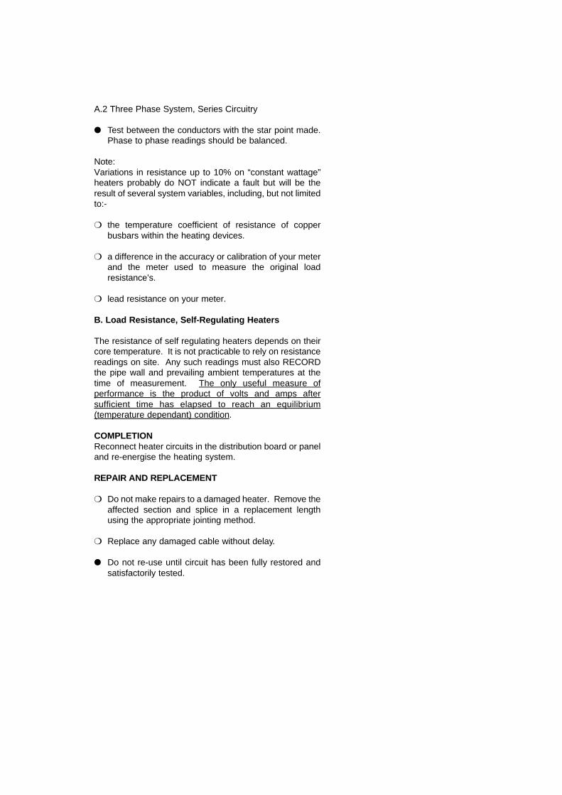
A.2 Three Phase System, Series Circuitry
Test between the conductors with the star point made.Phase to phase readings should be balanced.
Note:Variations in resistance up to 10% on “constant wattage”heaters probably do NOT indicate a fault but will be theresult of several system variables, including, but not limitedto:-
the temperature coefficient of resistance of copperbusbars within the heating devices.
a difference in the accuracy or calibration of your meterand the meter used to measure the original loadresistance’s.
lead resistance on your meter.
B. Load Resistance, Self-Regulating Heaters
The resistance of self regulating heaters depends on theircore temperature. It is not practicable to rely on resistancereadings on site. Any such readings must also RECORDthe pipe wall and prevailing ambient temperatures at thetime of measurement. The only useful measure ofperformance is the product of volts and amps aftersufficient time has elapsed to reach an equilibrium(temperature dependant) condition.
COMPLETIONReconnect heater circuits in the distribution board or paneland re-energise the heating system.
REPAIR AND REPLACEMENT
Do not make repairs to a damaged heater. Remove theaffected section and splice in a replacement lengthusing the appropriate jointing method.
Replace any damaged cable without delay.
Do not re-use until circuit has been fully restored andsatisfactorily tested.
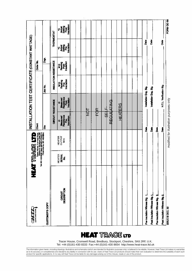
Tracer House, Cromwell Road, Bredbury, Stockport, Cheshire, SK6 2RF, U.K.Tel: +44 (0)161-430 8333 Fax:+44 (0)161-430 8654 http://www.heat-trace.ltd.uk
The information given herein, including drawings, illustrations and schematics (which are intended for illustration purposes only), is believed to be reliable. However, Heat Trace Ltd makes no warrantiesas to its accuracy or completeness and disclaims any liability in connection with its use. Users of Heat Trace Ltd products should make their own evaluation to determine the suitability of each suchproduct for specific applications. In no way will Heat Trace Ltd be liable for any damages arising out of the misuse, resale or use of the product.
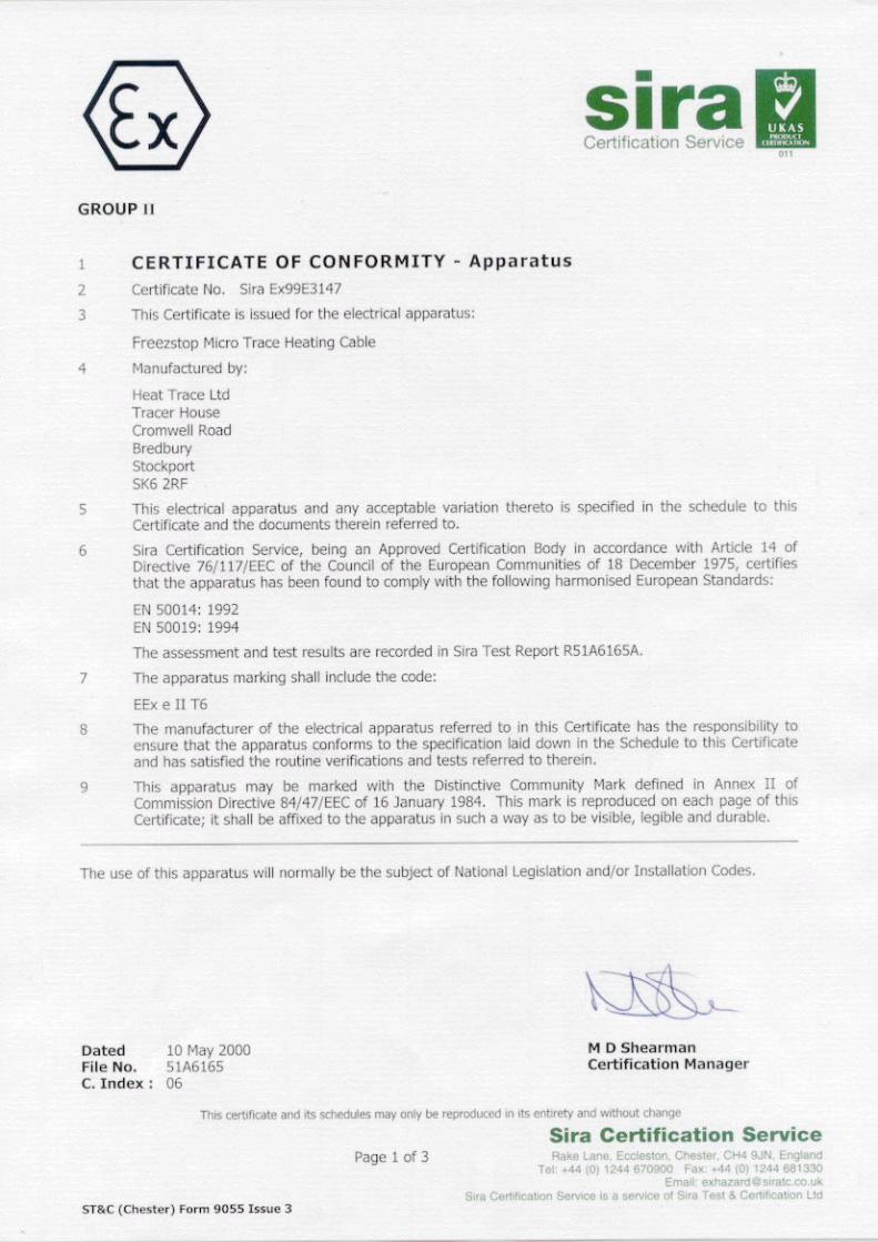
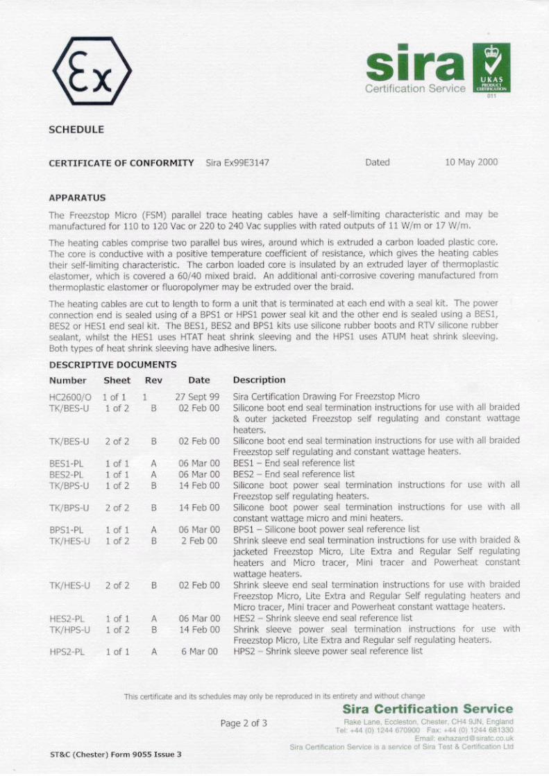
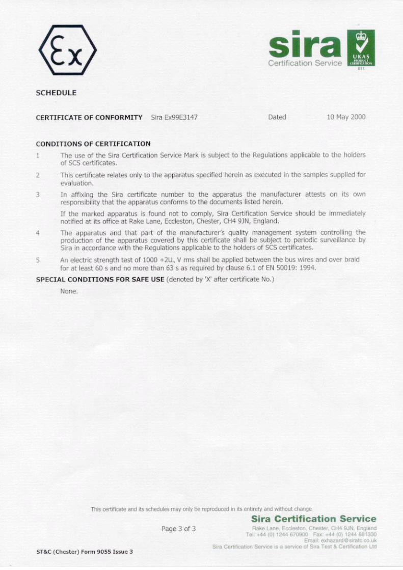
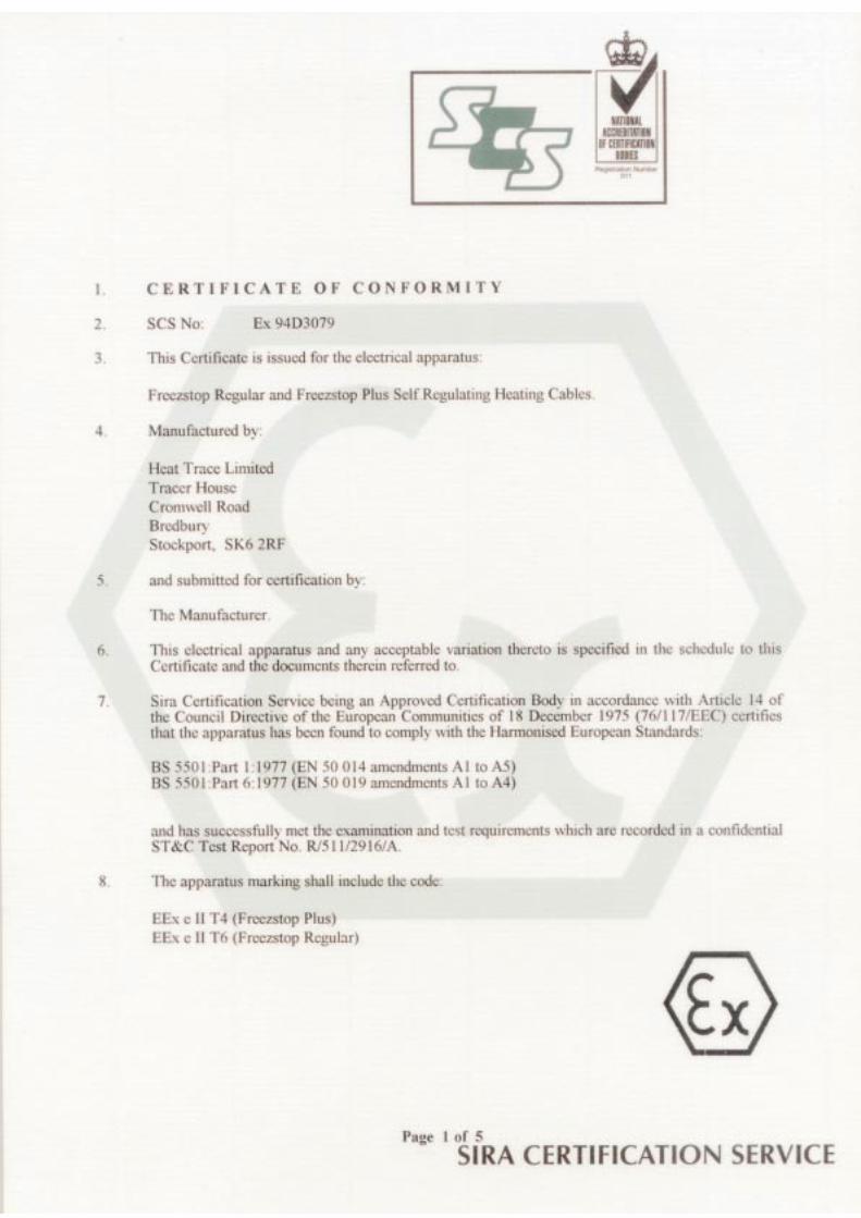
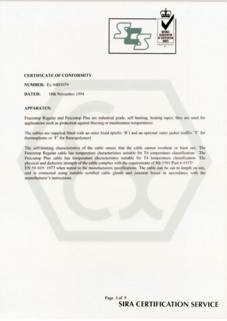
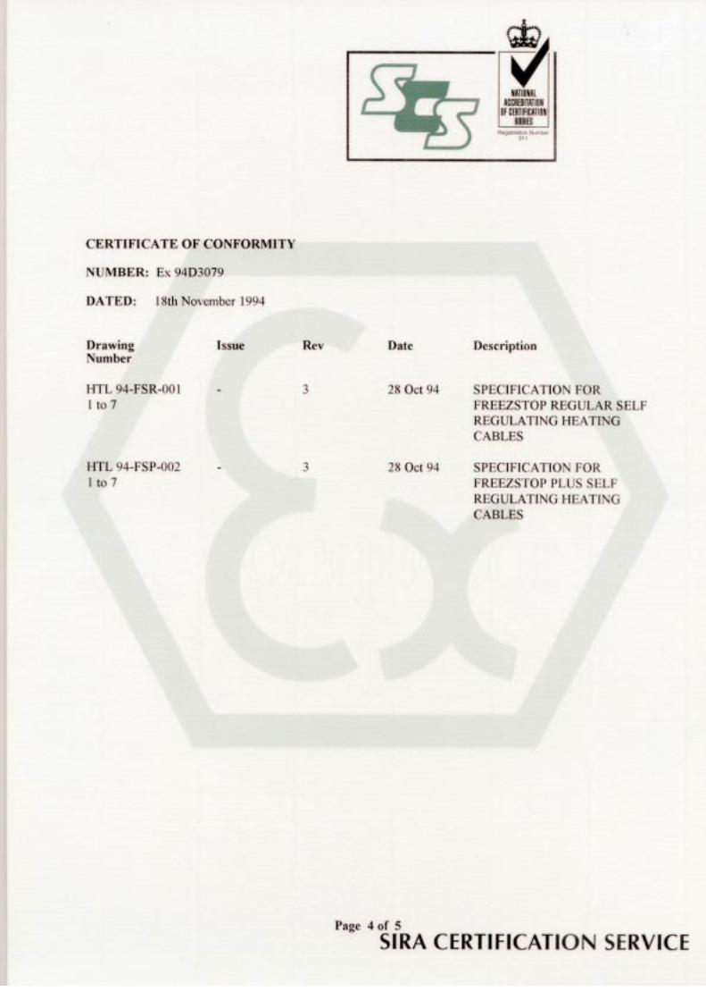
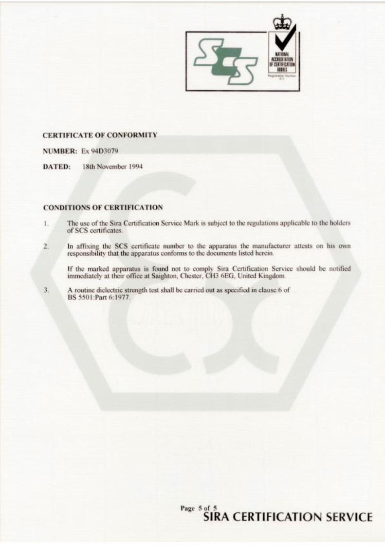
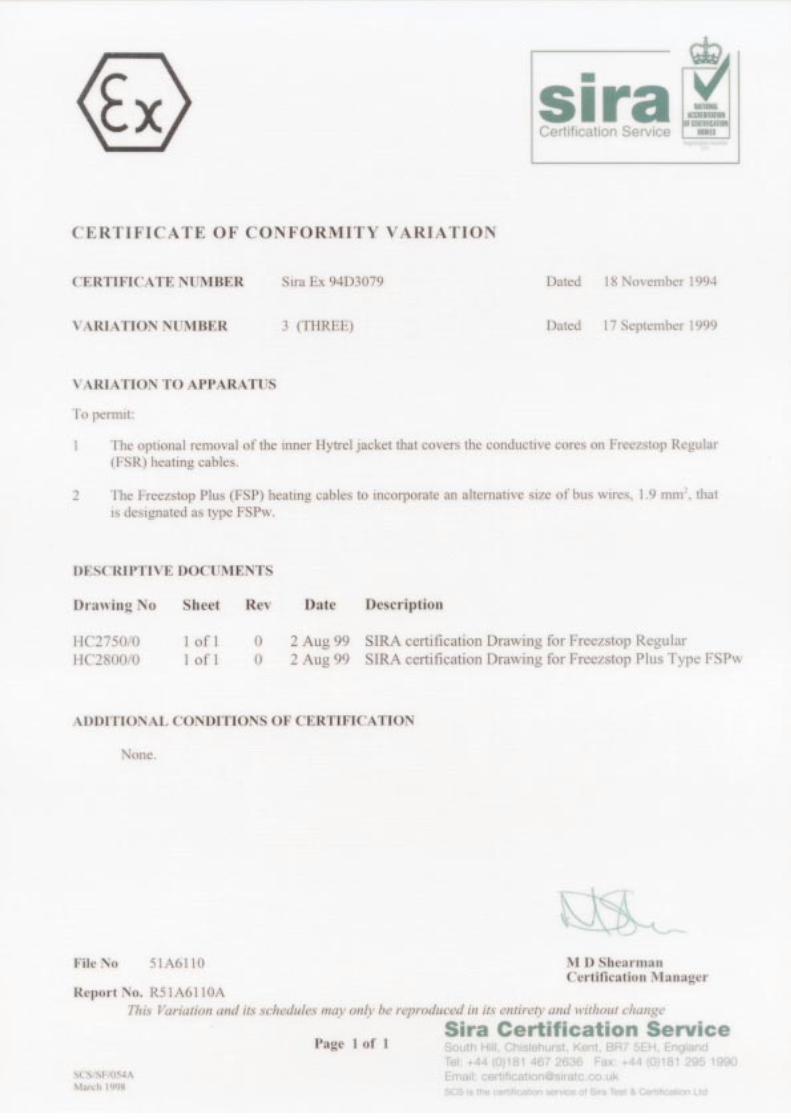
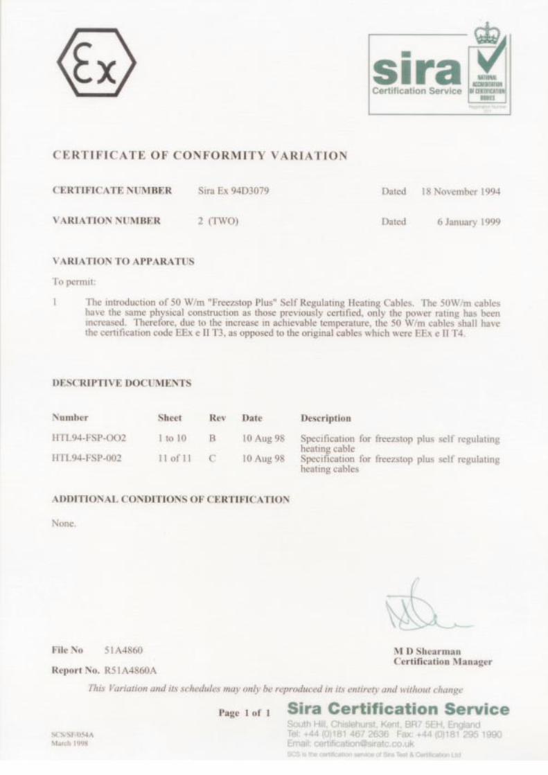

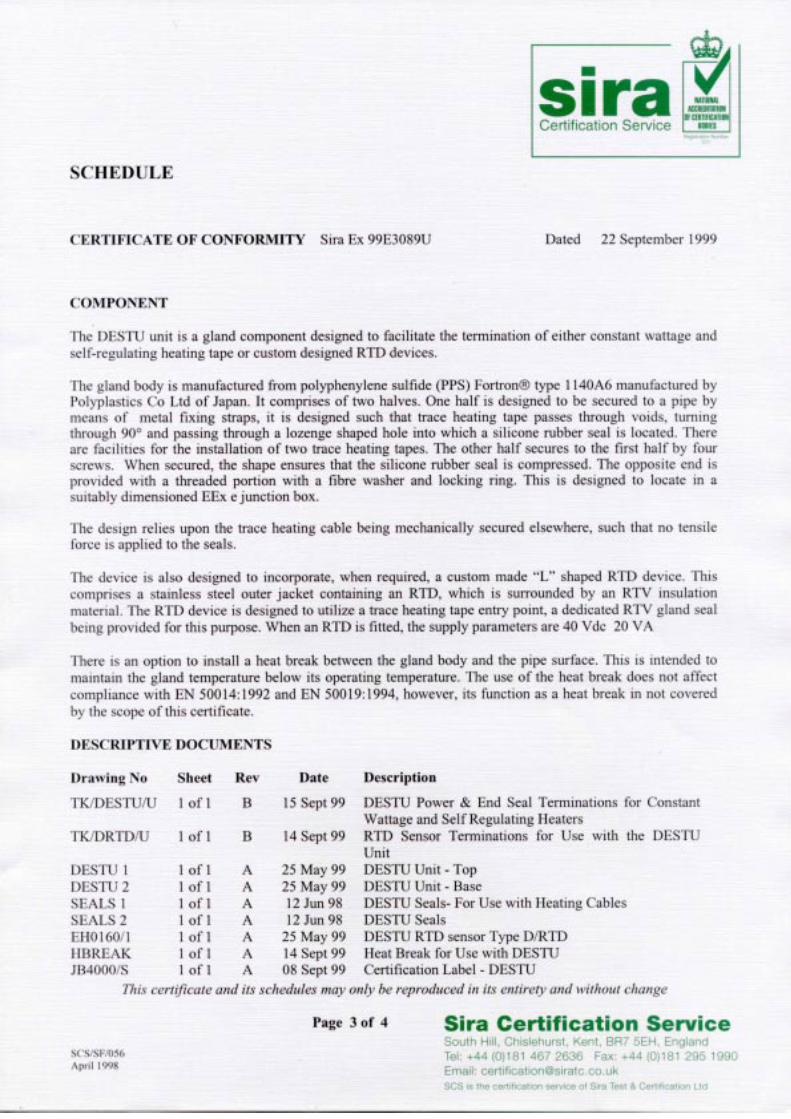
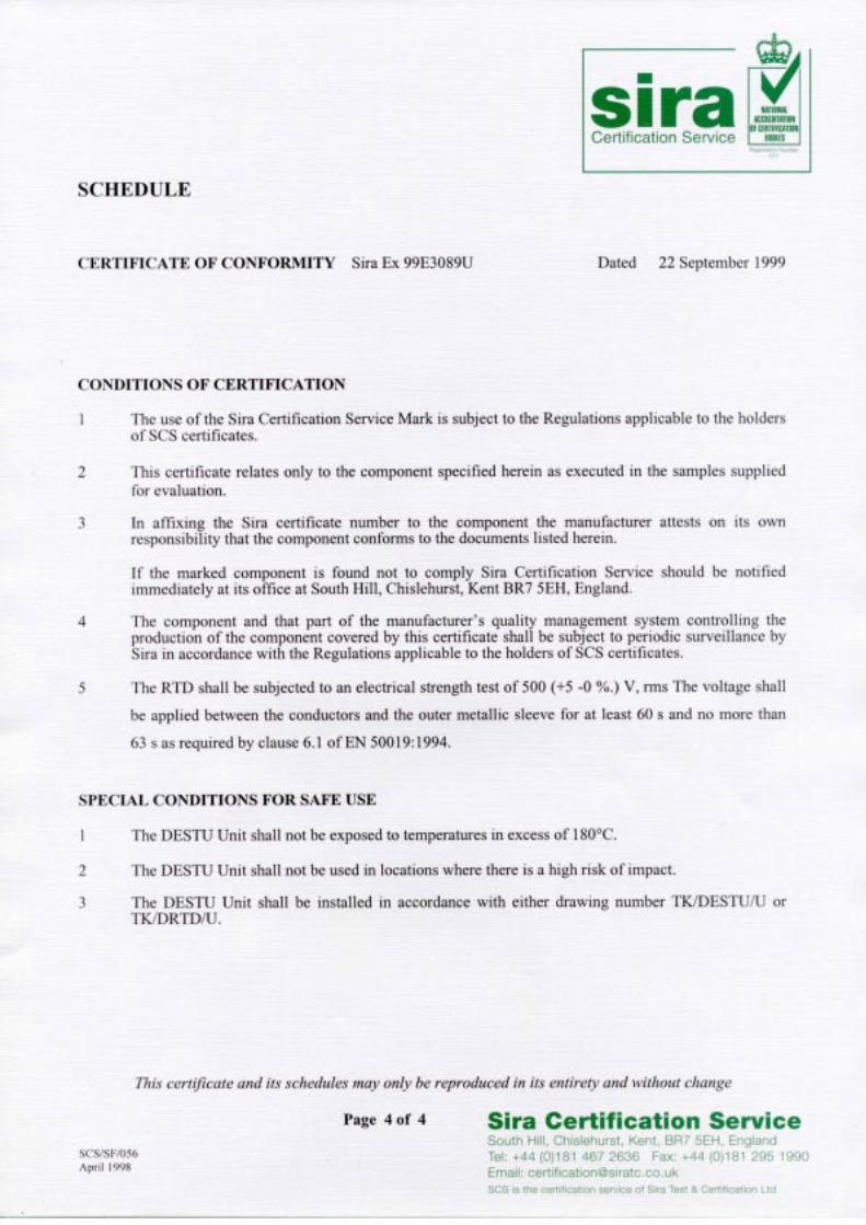
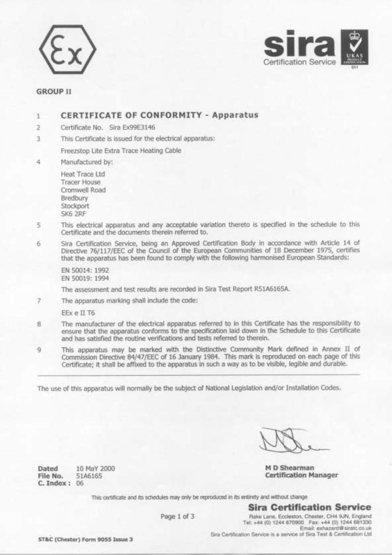
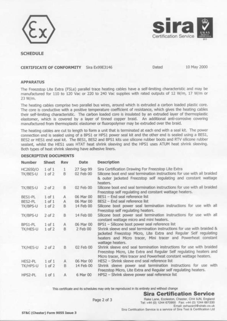
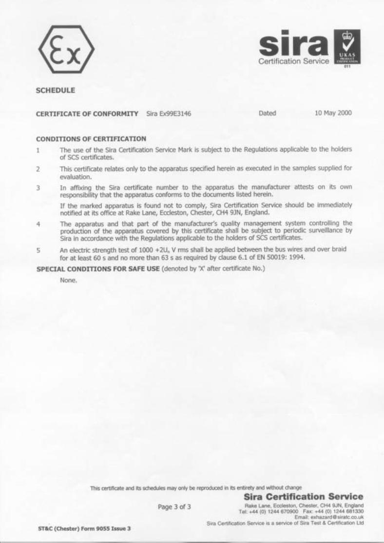
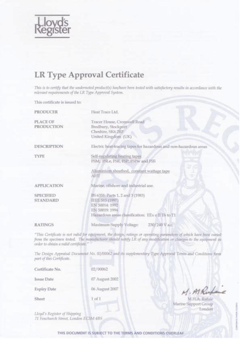
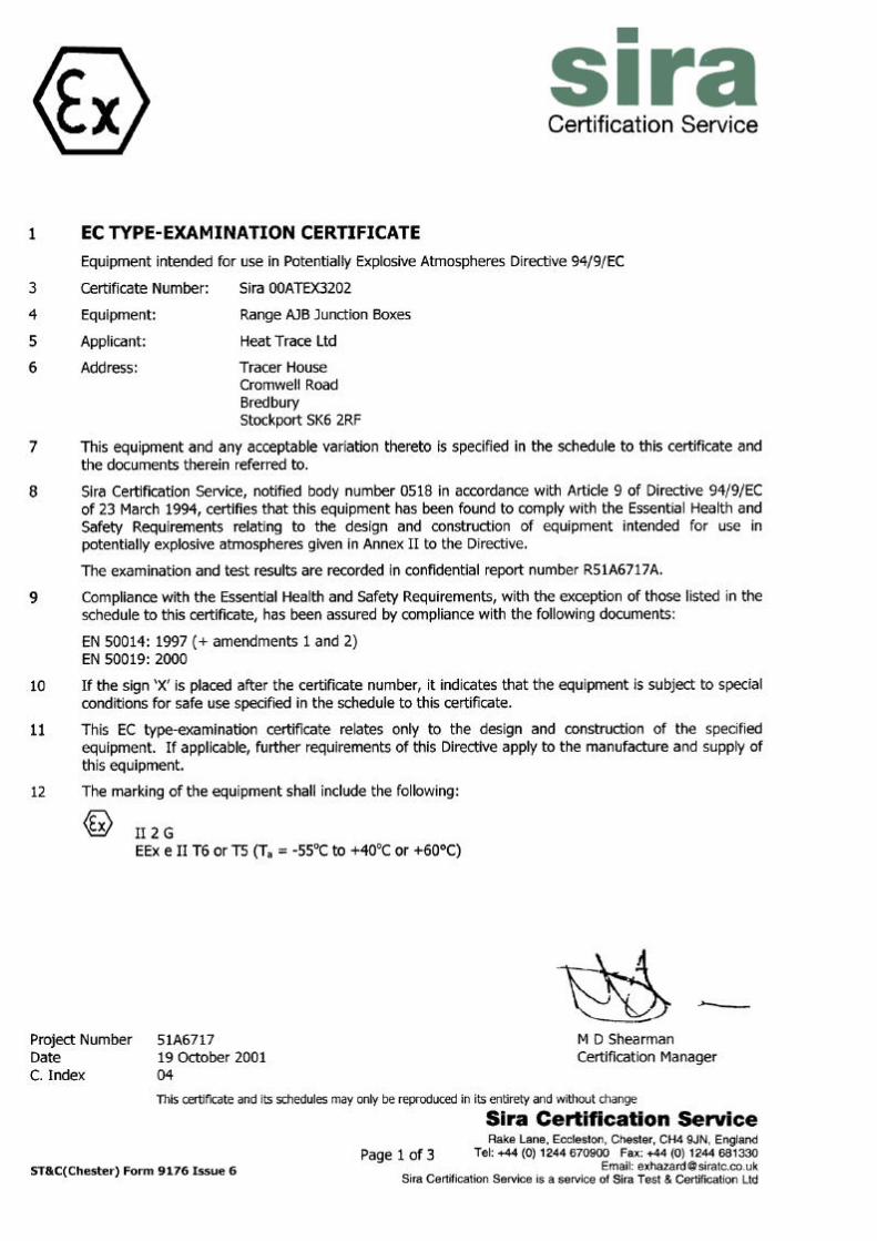
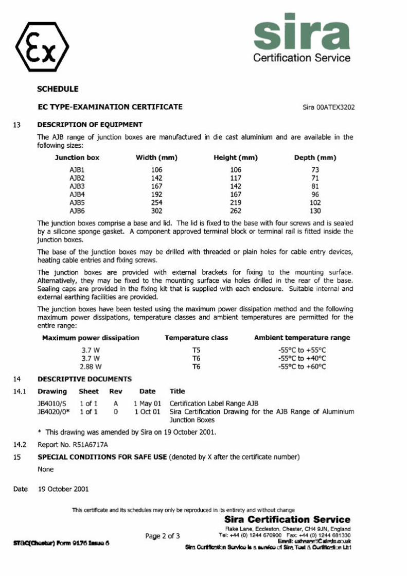
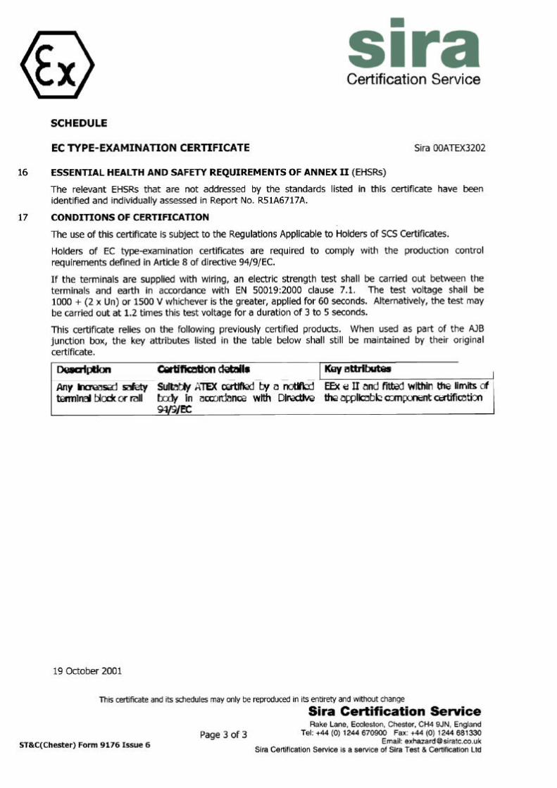
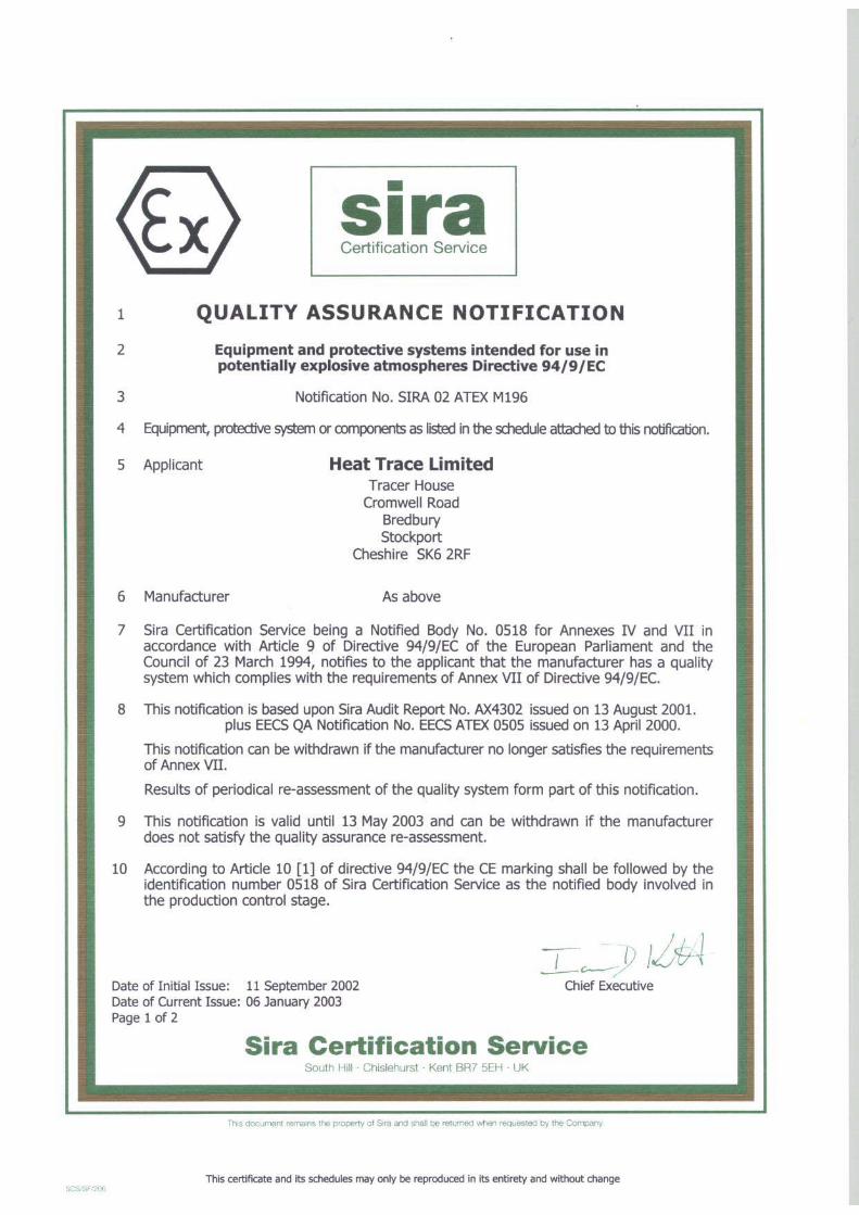
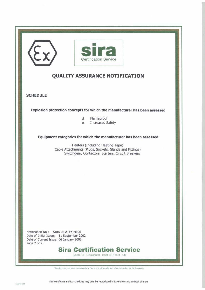
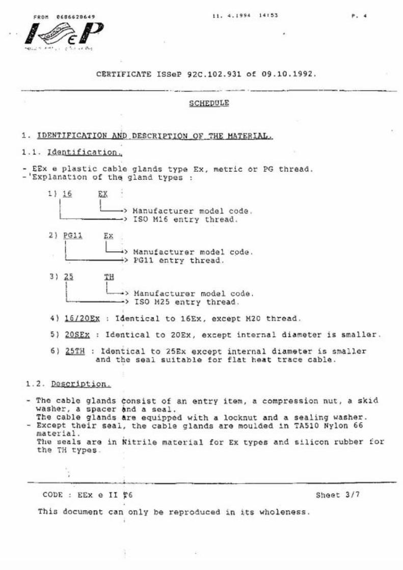
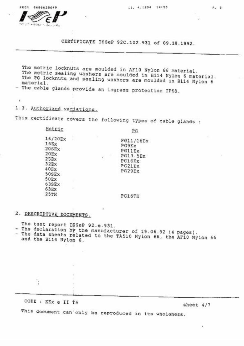
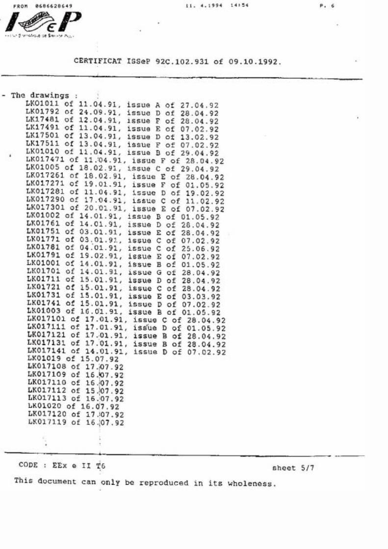
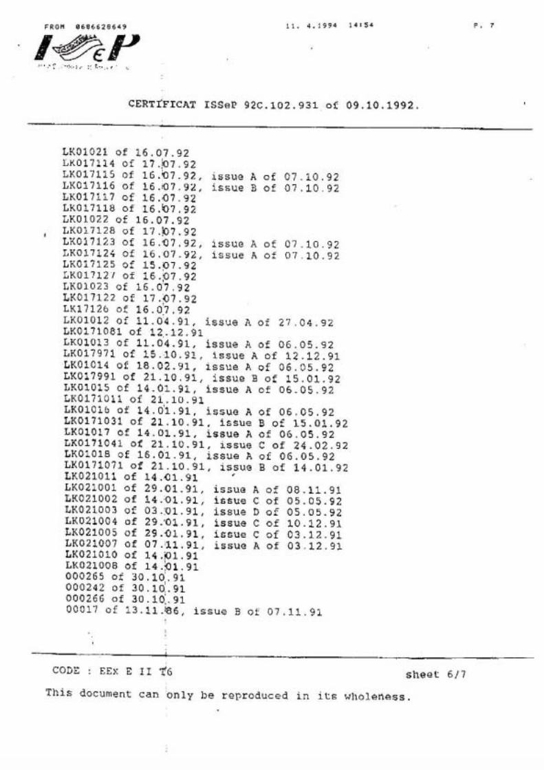
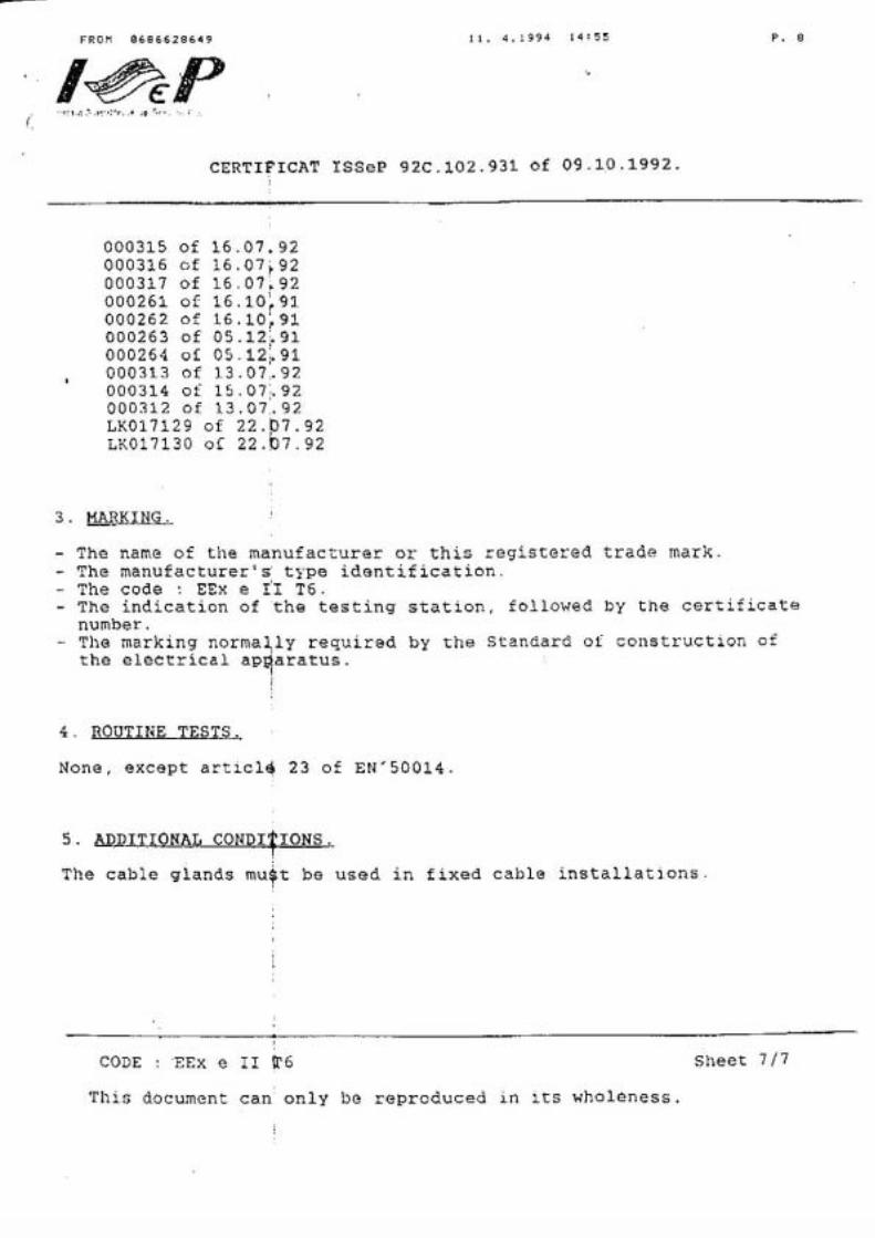
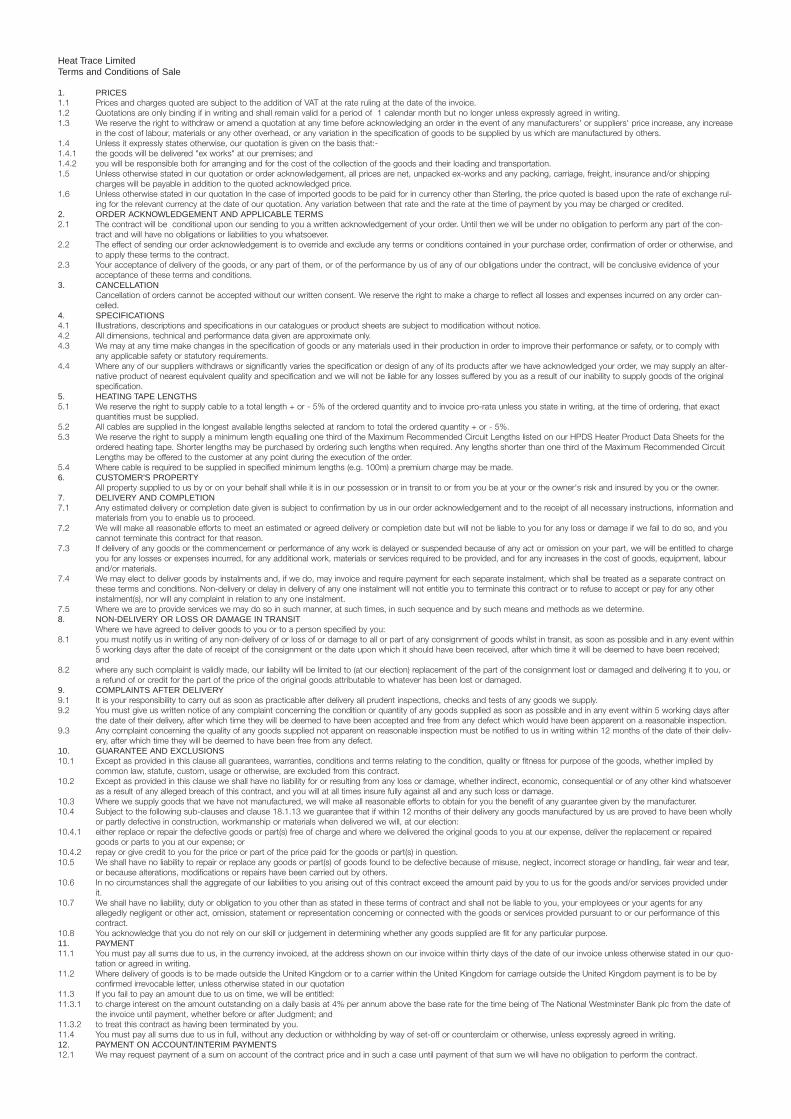
Heat Trace LimitedTerms and Conditions of Sale
1. PRICES1.1 Prices and charges quoted are subject to the addition of VAT at the rate ruling at the date of the invoice.1.2 Quotations are only binding if in writing and shall remain valid for a period of 1 calendar month but no longer unless expressly agreed in writing.1.3 We reserve the right to withdraw or amend a quotation at any time before acknowledging an order in the event of any manufacturers' or suppliers' price increase, any increase
in the cost of labour, materials or any other overhead, or any variation in the specification of goods to be supplied by us which are manufactured by others.1.4 Unless it expressly states otherwise, our quotation is given on the basis that:-1.4.1 the goods will be delivered "ex works" at our premises; and 1.4.2 you will be responsible both for arranging and for the cost of the collection of the goods and their loading and transportation.1.5 Unless otherwise stated in our quotation or order acknowledgement, all prices are net, unpacked ex-works and any packing, carriage, freight, insurance and/or shipping
charges will be payable in addition to the quoted acknowledged price.1.6 Unless otherwise stated in our quotation In the case of imported goods to be paid for in currency other than Sterling, the price quoted is based upon the rate of exchange rul-
ing for the relevant currency at the date of our quotation. Any variation between that rate and the rate at the time of payment by you may be charged or credited.2. ORDER ACKNOWLEDGEMENT AND APPLICABLE TERMS2.1 The contract will be conditional upon our sending to you a written acknowledgement of your order. Until then we will be under no obligation to perform any part of the con-
tract and will have no obligations or liabilities to you whatsoever.2.2 The effect of sending our order acknowledgement is to override and exclude any terms or conditions contained in your purchase order, confirmation of order or otherwise, and
to apply these terms to the contract.2.3 Your acceptance of delivery of the goods, or any part of them, or of the performance by us of any of our obligations under the contract, will be conclusive evidence of your
acceptance of these terms and conditions.3. CANCELLATION
Cancellation of orders cannot be accepted without our written consent. We reserve the right to make a charge to reflect all losses and expenses incurred on any order can-celled.
4. SPECIFICATIONS 4.1 Illustrations, descriptions and specifications in our catalogues or product sheets are subject to modification without notice.4.2 All dimensions, technical and performance data given are approximate only.4.3 We may at any time make changes in the specification of goods or any materials used in their production in order to improve their performance or safety, or to comply with
any applicable safety or statutory requirements.4.4 Where any of our suppliers withdraws or significantly varies the specification or design of any of its products after we have acknowledged your order, we may supply an alter-
native product of nearest equivalent quality and specification and we will not be liable for any losses suffered by you as a result of our inability to supply goods of the originalspecification.
5. HEATING TAPE LENGTHS5.1 We reserve the right to supply cable to a total length + or - 5% of the ordered quantity and to invoice pro-rata unless you state in writing, at the time of ordering, that exact
quantities must be supplied.5.2 All cables are supplied in the longest available lengths selected at random to total the ordered quantity + or - 5%. 5.3 We reserve the right to supply a minimum length equalling one third of the Maximum Recommended Circuit Lengths listed on our HPDS Heater Product Data Sheets for the
ordered heating tape. Shorter lengths may be purchased by ordering such lengths when required. Any lengths shorter than one third of the Maximum Recommended CircuitLengths may be offered to the customer at any point during the execution of the order.
5.4 Where cable is required to be supplied in specified minimum lengths (e.g. 100m) a premium charge may be made.6. CUSTOMER'S PROPERTY
All property supplied to us by or on your behalf shall while it is in our possession or in transit to or from you be at your or the owner's risk and insured by you or the owner.7. DELIVERY AND COMPLETION 7.1 Any estimated delivery or completion date given is subject to confirmation by us in our order acknowledgement and to the receipt of all necessary instructions, information and
materials from you to enable us to proceed.7.2 We will make all reasonable efforts to meet an estimated or agreed delivery or completion date but will not be liable to you for any loss or damage if we fail to do so, and you
cannot terminate this contract for that reason.7.3 If delivery of any goods or the commencement or performance of any work is delayed or suspended because of any act or omission on your part, we will be entitled to charge
you for any losses or expenses incurred, for any additional work, materials or services required to be provided, and for any increases in the cost of goods, equipment, labourand/or materials.
7.4 We may elect to deliver goods by instalments and, if we do, may invoice and require payment for each separate instalment, which shall be treated as a separate contract onthese terms and conditions. Non-delivery or delay in delivery of any one instalment will not entitle you to terminate this contract or to refuse to accept or pay for any otherinstalment(s), nor will any complaint in relation to any one instalment.
7.5 Where we are to provide services we may do so in such manner, at such times, in such sequence and by such means and methods as we determine.8. NON-DELIVERY OR LOSS OR DAMAGE IN TRANSIT
Where we have agreed to deliver goods to you or to a person specified by you:8.1 you must notify us in writing of any non-delivery of or loss of or damage to all or part of any consignment of goods whilst in transit, as soon as possible and in any event within
5 working days after the date of receipt of the consignment or the date upon which it should have been received, after which time it will be deemed to have been received;and
8.2 where any such complaint is validly made, our liability will be limited to (at our election) replacement of the part of the consignment lost or damaged and delivering it to you, ora refund of or credit for the part of the price of the original goods attributable to whatever has been lost or damaged.
9. COMPLAINTS AFTER DELIVERY9.1 It is your responsibility to carry out as soon as practicable after delivery all prudent inspections, checks and tests of any goods we supply.9.2 You must give us written notice of any complaint concerning the condition or quantity of any goods supplied as soon as possible and in any event within 5 working days after
the date of their delivery, after which time they will be deemed to have been accepted and free from any defect which would have been apparent on a reasonable inspection.9.3 Any complaint concerning the quality of any goods supplied not apparent on reasonable inspection must be notified to us in writing within 12 months of the date of their deliv-
ery, after which time they will be deemed to have been free from any defect.10. GUARANTEE AND EXCLUSIONS10.1 Except as provided in this clause all guarantees, warranties, conditions and terms relating to the condition, quality or fitness for purpose of the goods, whether implied by
common law, statute, custom, usage or otherwise, are excluded from this contract.10.2 Except as provided in this clause we shall have no liability for or resulting from any loss or damage, whether indirect, economic, consequential or of any other kind whatsoever
as a result of any alleged breach of this contract, and you will at all times insure fully against all and any such loss or damage.10.3 Where we supply goods that we have not manufactured, we will make all reasonable efforts to obtain for you the benefit of any guarantee given by the manufacturer.10.4 Subject to the following sub-clauses and clause 18.1.13 we guarantee that if within 12 months of their delivery any goods manufactured by us are proved to have been wholly
or partly defective in construction, workmanship or materials when delivered we will, at our election:10.4.1 either replace or repair the defective goods or part(s) free of charge and where we delivered the original goods to you at our expense, deliver the replacement or repaired
goods or parts to you at our expense; or10.4.2 repay or give credit to you for the price or part of the price paid for the goods or part(s) in question.10.5 We shall have no liability to repair or replace any goods or part(s) of goods found to be defective because of misuse, neglect, incorrect storage or handling, fair wear and tear,
or because alterations, modifications or repairs have been carried out by others.10.6 In no circumstances shall the aggregate of our liabilities to you arising out of this contract exceed the amount paid by you to us for the goods and/or services provided under
it.10.7 We shall have no liability, duty or obligation to you other than as stated in these terms of contract and shall not be liable to you, your employees or your agents for any
allegedly negligent or other act, omission, statement or representation concerning or connected with the goods or services provided pursuant to or our performance of thiscontract.
10.8 You acknowledge that you do not rely on our skill or judgement in determining whether any goods supplied are fit for any particular purpose.11. PAYMENT11.1 You must pay all sums due to us, in the currency invoiced, at the address shown on our invoice within thirty days of the date of our invoice unless otherwise stated in our quo-
tation or agreed in writing.11.2 Where delivery of goods is to be made outside the United Kingdom or to a carrier within the United Kingdom for carriage outside the United Kingdom payment is to be by
confirmed irrevocable letter, unless otherwise stated in our quotation11.3 If you fail to pay an amount due to us on time, we will be entitled:11.3.1 to charge interest on the amount outstanding on a daily basis at 4% per annum above the base rate for the time being of The National Westminster Bank plc from the date of
the invoice until payment, whether before or after Judgment; and11.3.2 to treat this contract as having been terminated by you. 11.4 You must pay all sums due to us in full, without any deduction or withholding by way of set-off or counterclaim or otherwise, unless expressly agreed in writing.12. PAYMENT ON ACCOUNT/INTERIM PAYMENTS12.1 We may request payment of a sum on account of the contract price and in such a case until payment of that sum we will have no obligation to perform the contract.
12.2 We may at any stage request in writing an interim payment or interim payments on account of the contract price. If you fail to make any such payment within the time speci-fied by us, we may elect to treat the contract as having been terminated by you.
13. RISKOnce we have delivered goods to you, your employee or agent, they shall be at your risk and you will be responsible for insuring them.
14. RETENTION OF TITLE TO GOODS14.1 Notwithstanding delivery of goods and the passing of risk to you, we will retain legal and equitable ownership of goods supplied to you ("the Goods") until you have paid:-14.1.1 all sums due to us under this contract, and 14.1.2 all other sums owed by you to us under any contract or otherwise.14.2 While we retain legal and equitable ownership of the Goods you will:14.2.1 retain possession of them as bailee and fiduciary agent for us; 14.2.2 keep them separate from other goods, at a location and in conditions acceptable to us and clearly identified as our property;14.2.3 if so requested by us, at your own expense immediately re-deliver them to us or to our order;14.2.4 at any time permit us, our employees, agents, or assignees to enter any land, building or premises to examine and/or recover possession of the Goods or any part of them (by
separating them from other goods or equipment if need be).14.3 While we retain legal and equitable ownership of the Goods, you will:-14.3.1 have or effect suitable insurance covering their full value;14.3.2 in the event of any loss of or damage to them or any part of them, make a claim under the policy of insurance and hold any proceeds of that claim on trust for us and in a
separate and clearly identifiable fund, and immediately account for such proceeds to us on request;14.3.3 have no power or right to use, sell, charge or dispose of them or any interest in any part of them whether in the ordinary course of your business or otherwise.14.4 For the avoidance of any doubt it is agreed and declared that it is not intended that the above provisions should operate to create a charge of any kind in our favour over any
property of yours.15. FORCE MAJEURE15.1 We will have no liability to you if we are prevented from or delayed in carrying out any part of this contract by any event beyond our control including (without limitation) any act
of God, legislation, war, fire, flood, drought, failure of power supply, lock-out, strike or trade dispute, or inability to obtain materials required for the performance of the contract.15.2 If in any such case we decide that it will be impossible or uneconomic to complete the contract, we shall be entitled to treat it as having been terminated.16. INTELLECTUAL PROPERTY 16.1 All copyrights, design rights and intellectual property rights of any kind whatsoever in respect of any object or thing created or made by us for the purposes of or in connection
with this contract will remain our property.16.2 Where goods are supplied with our badge attached, you will not in any way deface, obliterate or remove that badge, nor cause or permit any other badge to be attached to
the goods without our prior consent in writing.17. CUSTOMERS DESIGN OR SPECIFICATION
Where goods are made or adapted by us to or in accordance with your design, specification or requirements, you will indemnify us fully in respect of any injury, loss, expense,or damage caused to any third party for which we may be held liable as a result of our having carried out your requirement(s).
18. CUSTOMER'S OTHER OBLIGATIONS18.1 You will:18.1.1 ensure that a clear, suitable and readily accessible site is available and ready for the installation of equipment;18.1.2 permit us (and our employees or agents) to enter your land or premises and, where alternative routes or means of access are available, to make use of the route or means of
access which we consider to be the most practicable for the proper performance of the work;18.1.3 ensure that you or your authorised representative are or is present at the required place and time to take delivery of any goods to be delivered by us under this contract, and
that you or your representative signs a delivery note when requested to do so.18.1.4 upon delivery or completion of the contract programme sign, either personally or by an authorised representative, a note confirming satisfactory delivery or completion (as the
case may be) and where appropriate pay the balance of all monies then due under the contract.18.1.5 at your own expense provide satisfactory sources and unrestricted use of electricity, gas and water during the continuance of the work.18.1.6 on request, provide us with evidence of insurance cover of the type(s) and amount(s) specified by us; 18.1.7 comply with any applicable statutory or other regulations, byelaws or requirements, and obtain any licences or permissions, which may be necessary for the performance of
the work and/or likely to affect the health and/or safety of our employees or agents.18.1.8 ensure that all internal and external structures on or over which our employees or agents must work or pass, and all electrical, gas, water and other systems are in safe and
sound condition;18.1.9 promptly provide all materials and instructions we require in order to perform the contract;18.1.10 ensure that all goods or equipment supplied or installed by us is or are operated at all times in accordance with any applicable operating instructions and all applicable laws
and regulations, and that all necessary safety equipment, permissions and/or consents are obtained;18.1.11 indemnify us in respect of any loss, expense, damage, penalty or legal liability suffered by us [or any servant or agent of ours] as a result of anything done by us on your
instructions or at your request;18.1.12 request a reasonable time before delivery any test certificates that may be required, and pay our reasonable charges for supplying the same;18.1.13 if you contend that any goods supplied by us are defective or damaged or otherwise not in accordance with the contract, allow us the opportunity to inspect the goods in
question as soon as is practicable and permit us to carry out any repair or replacement work for which we are liable under this contract.18.2 We may decline to carry out your instructions if, in our opinion, compliance would involve a contravention of the law or be likely to prejudice the health and/or safety of any of
our employees or agents.18.3 Where for the purposes of this contract (whether at our request or not) you provide or procure the provision by a third person of any sample of material to enable us to deter-
mine how to produce or design goods, or provide services, you warrant that the sample supplied conforms exactly to your requirements.18.4 Where to enable us to perform the contract you are to provide or procure the provision by some third person of any material, it must be supplied to us in exactly the quantity
and form we specify.18.5 If you breach any of the above obligations or any other obligation imposed upon you by the contract, we will be entitled to treat it as having been terminated by you.19. TERMINATION 19.1 In addition to any other specific rights we may have under this contract or the law either to terminate it or treat it as having been terminated, we may so treat it if you commit
any substantial breach of the contract, become bankrupt or are dissolved, or (if you are a corporate body) you go into liquidation, administration or receivership or make anarrangement or composition with your creditors, or have any Judgment entered against you or have distress or execution levied against your goods.
19.2 Where this contract is terminated or we are entitled to treat it as having been terminated:-19.2.1 we will not be obliged to perform the remainder of this contract or any other contract with you; 19.2.2 we will be entitled to immediate payment of the total outstanding in respect of all invoices rendered to you;19.3 we will be entitled to render an invoice to you for immediate payment in respect of any goods, materials, work or services supplied or performed under the contract and any
other contract with you.20. INDEMNITY 20.1 Without prejudice to any right we may have to terminate this agreement, you will on demand indemnify us in respect of all losses, expenses, damages, penalties or costs
incurred by us:-20.1.1 as a result of any breach or in order to secure proper performance by you of any provision of this contract; and20.1.2 in respect of any claim(s) or proceedings brought against us or any servant or agent of ours by any other person as a result of our performance of any obligation to you under
this contract,including in the latter case any amount paid by us on legal advice in settlement of any claim.
20.2 You will in addition on demand indemnify us in respect of all costs, expenses, charges, fees or expenses incurred by us in connection with any proceedings or disputebetween us arising out of or in connection with this contract or the recovery by us of any property or money.
21. SUB-CONTRACTING We may sub-contract any part of the contract and in such a case your obligations to us will extend to our sub-contractor(s).
22. ASSIGNMENT You may not assign any right or benefit under this contract to any other person without our prior written consent.
23. THIRD PARTY RIGHTSA person who is not a party to the contract between us shall have no right under the Contracts (Rights of Third Parties) Act 1999 to enforce or enjoy the benefit of any term ofthe contract.
24. LAW AND JURISDICTION 24.1 This contract and any dispute arising in connection with it shall be in all respects subject to and determined in accordance with English Law.24.2 In the event of any dispute:24.2.1 the civil courts within whose district our principal place of business is situated shall have exclusive jurisdiction according to their respective competences; and24.2.2 you will not apply for or concur in the transfer of any proceedings between us to any other court.25. ENTIRE AGREEMENT
Our quotation and these Terms constitute the entire agreement between the two of us, and no representation or warranty made orally by any person on our behalf shall haveany legal effect.
26. VARIATIONNo variation of these terms of contract shall be binding unless it is confirmed in writing and signed by a Director on our behalf.
STC2 August 2001
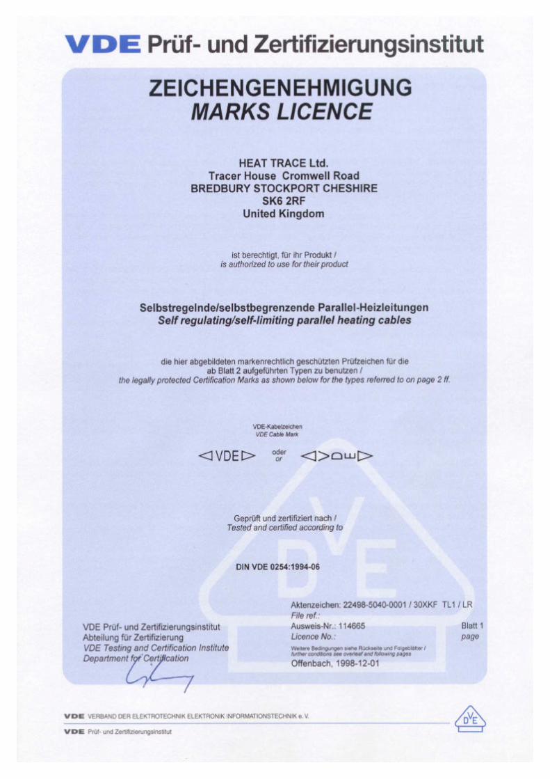
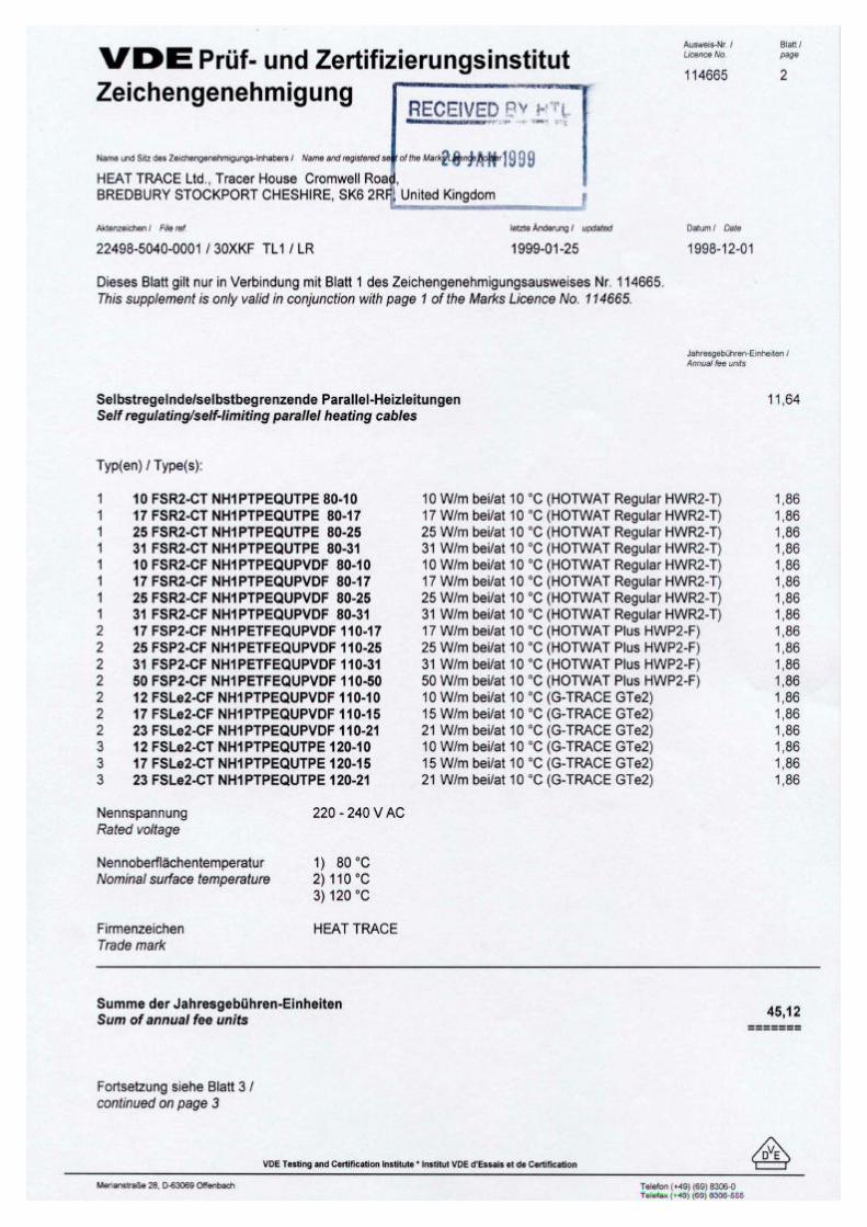
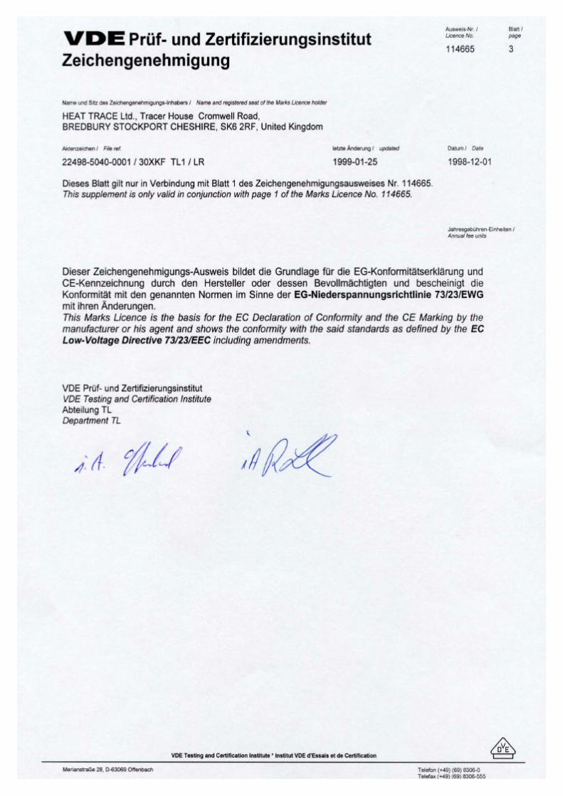
LG Cable
An LG Aff i l iated Company
Heat Trace Ltd, Cromwell Road, Bredbury, Stockport, SK6 2RF, Cheshire, England, U.K.
Telephone: +44 (0)161-430 8333 Facsimile: +44 (0)161-430 8654
http://www.heat-trace.com
Directors : N S Malone L Smith S Rothwell J W Young J F P Parsons M S Seo E T Chung P de Soet Registered in England No. 1573447
October 2000 To Whom It May Concern: Subject: HTL Type B RTD sensor We understand that you have asked us for a Certificate for our Type B, RTD Pt100 sensors as supplied to your site. We do not have a certificate for these devices, which are constructed along lines suggested many years ago by our friends at BASEEFA. At that time we were advised to ensure a minimum of 3mm thickness of electrical insulation between the Pt100 sensor and the surrounding metal wall. Accordingly we increased the diameter of the encapsulation tube from 6mm o.d. to 12mm o.d. This change is reflected in the attached copy of a later HTL Internal Drawing ID-91-009 that shows the safe area Type A and hazardous area Type B sensors. Please ignore the reference to thermowells. These sensors are used as pipe wall surface mount, air temperature sensing and thermowell sited units. At the time of the discussions with BASEEFA, the only relevant “Type of Protection” was Ex’s’, which was a catch-all concept but did not suggest a satisfactory “test” against which something could be certified. The idea of protection by encapsulation was germinating, but again there was no Standard in existence against which to test. We made the “beefed-up” version of our standard sensor and checked to ensure no transmission of energy even with 415 volts applied to the sensor. Of course we now have the encapsulation Standard, Type of Protection Ex’m’ to BS 5501: Part 8: 1988, but Heat Trace Ltd have never felt the need to follow-up with an approval for the Type B sensor, which has enjoyed unchallenged and successful operation in a great many installations for the last 25 years. A very few customers have asked for a pipe mounted sensor unit capable of formal Approval in a hazardous area, when we have recommended that a suitable Zener diode barrier be placed between the (safe area) Control and Distribution Panel and the field mounted sensor. More lately we have addressed the need for a simple Pt100 sensor having a reasonably fast response and a formal Approval. The unit is a specially formed tube otherwise similar to the smaller Type A sensor. This is our DESTU/RTD sensor which is used with a DESTU transition piece on pipes up to 240°C and any suitable Ex’e’ enclosure. The power handling limit is 40V DC, 20VA. Certificate No. SIRA 99 E3089U. With an Approval on a protected Type A construction when used in an electric heat tracing application, we are quite certain that you will have no problems with a massively reinforced Type B construction used underneath a thickness of thermal insulation. Yours sincerely, J W Young Engineering Director
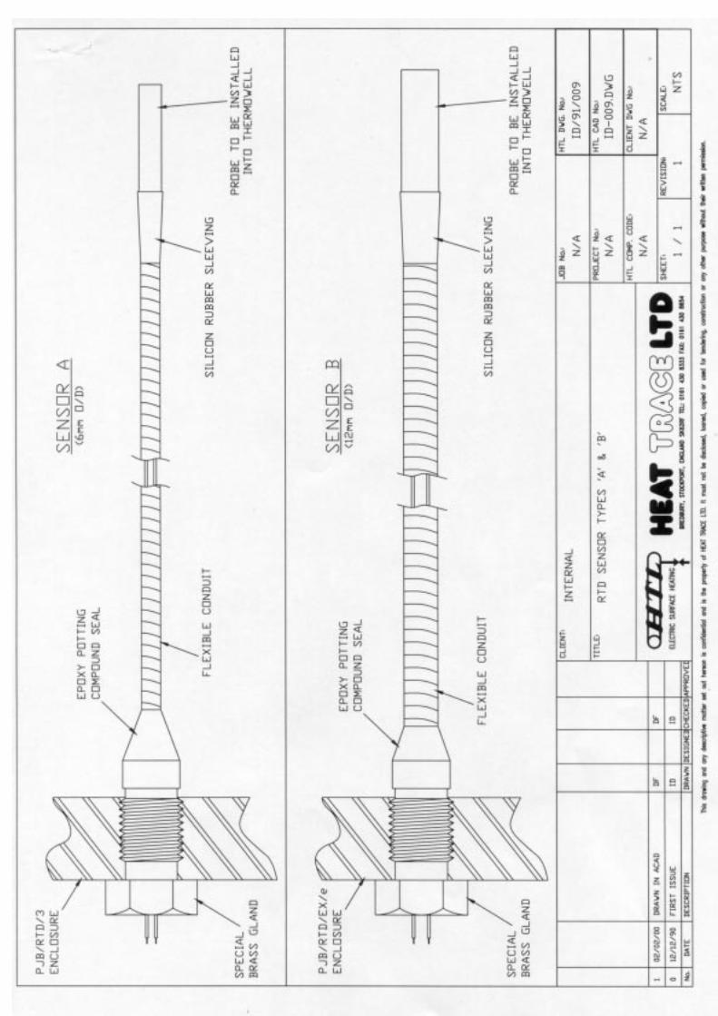
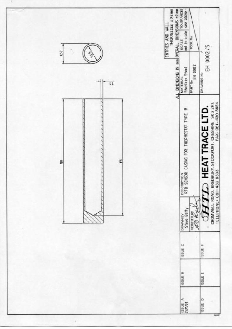
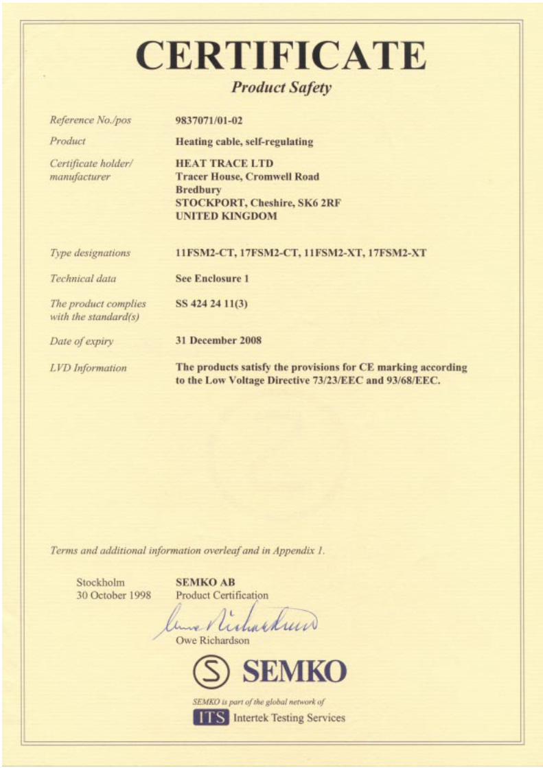
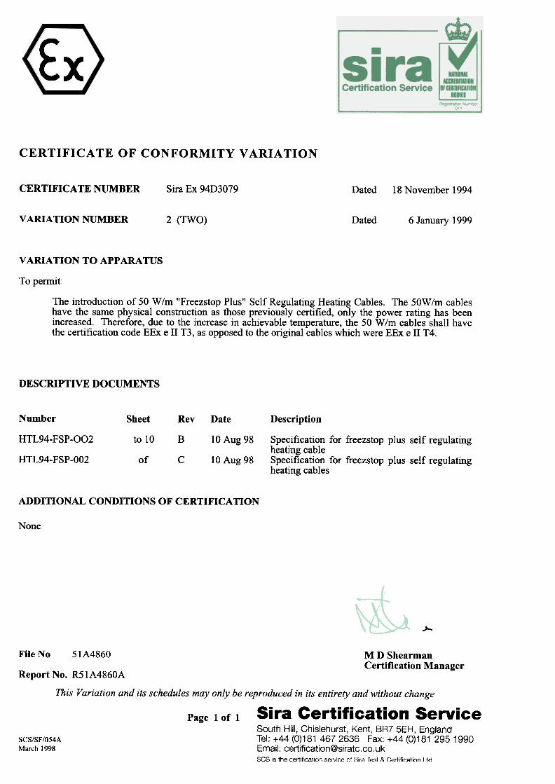
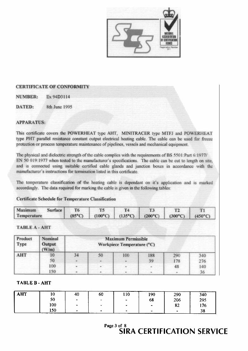
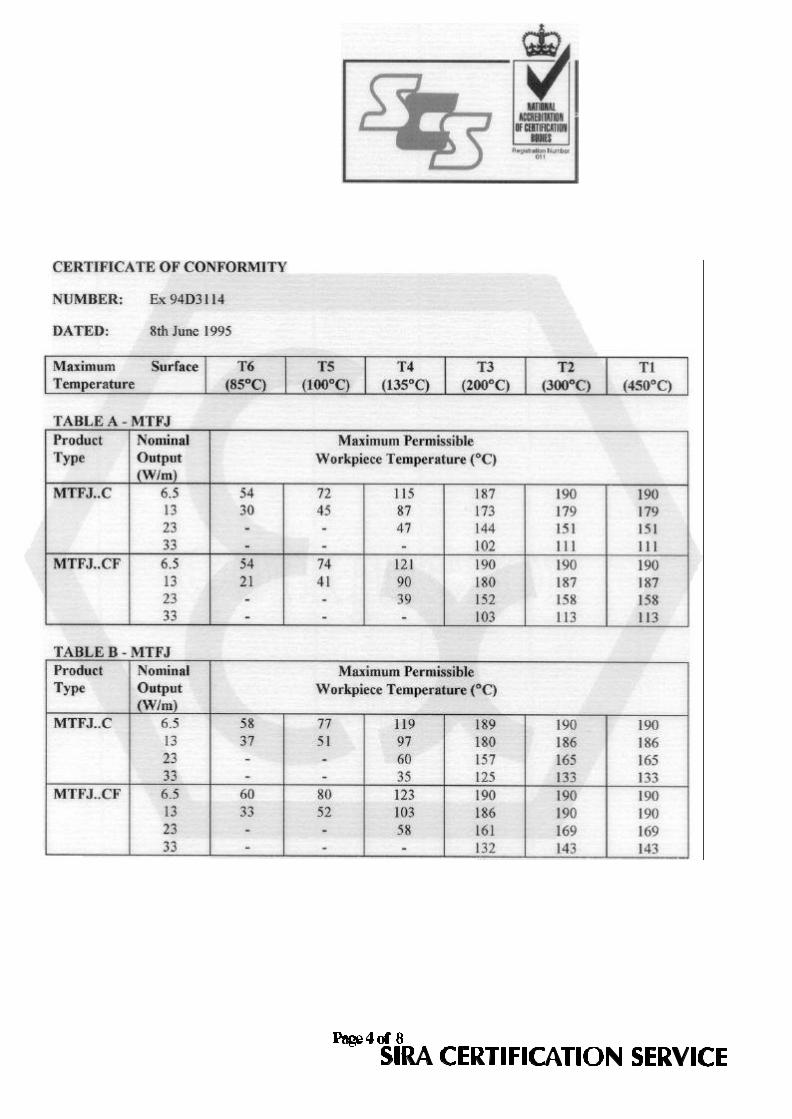
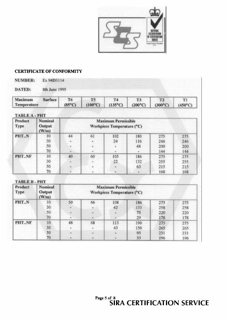
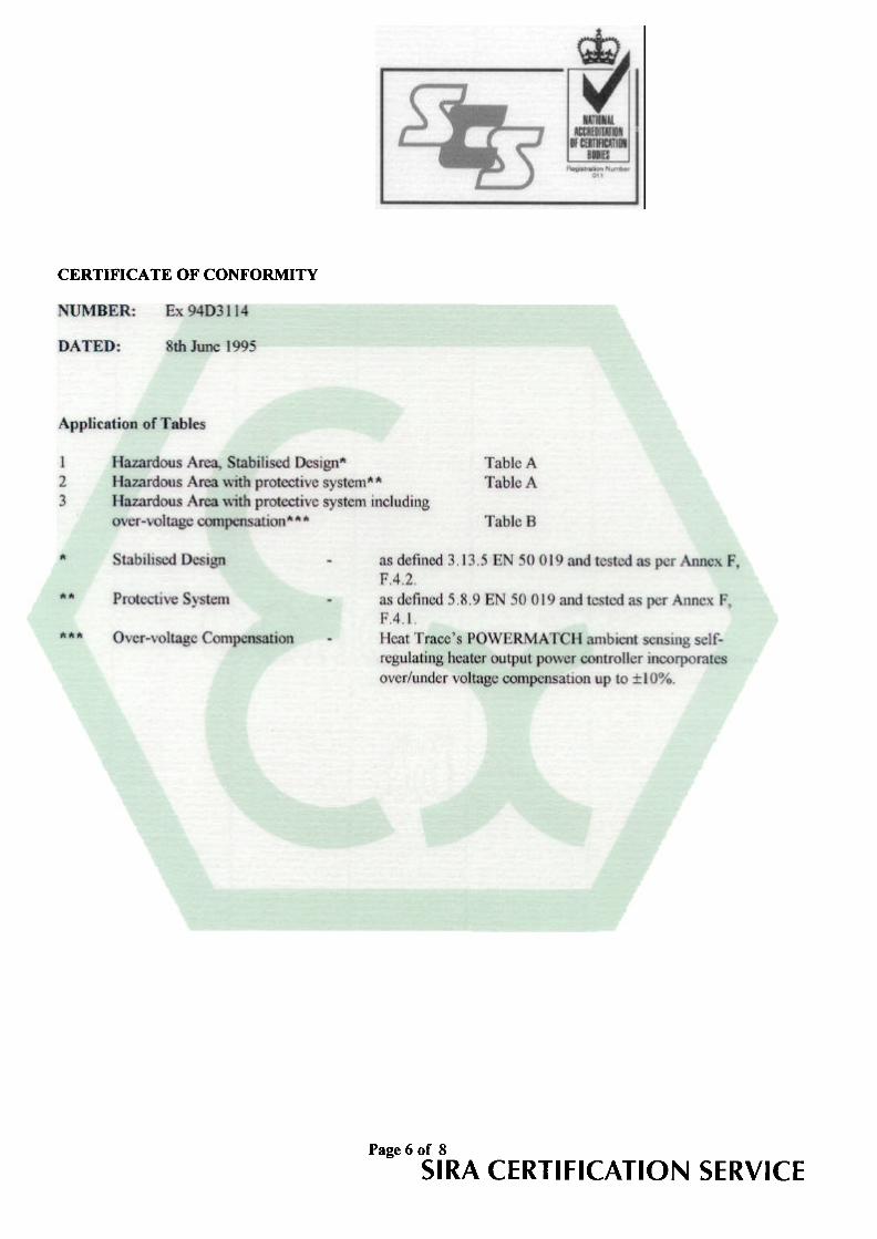
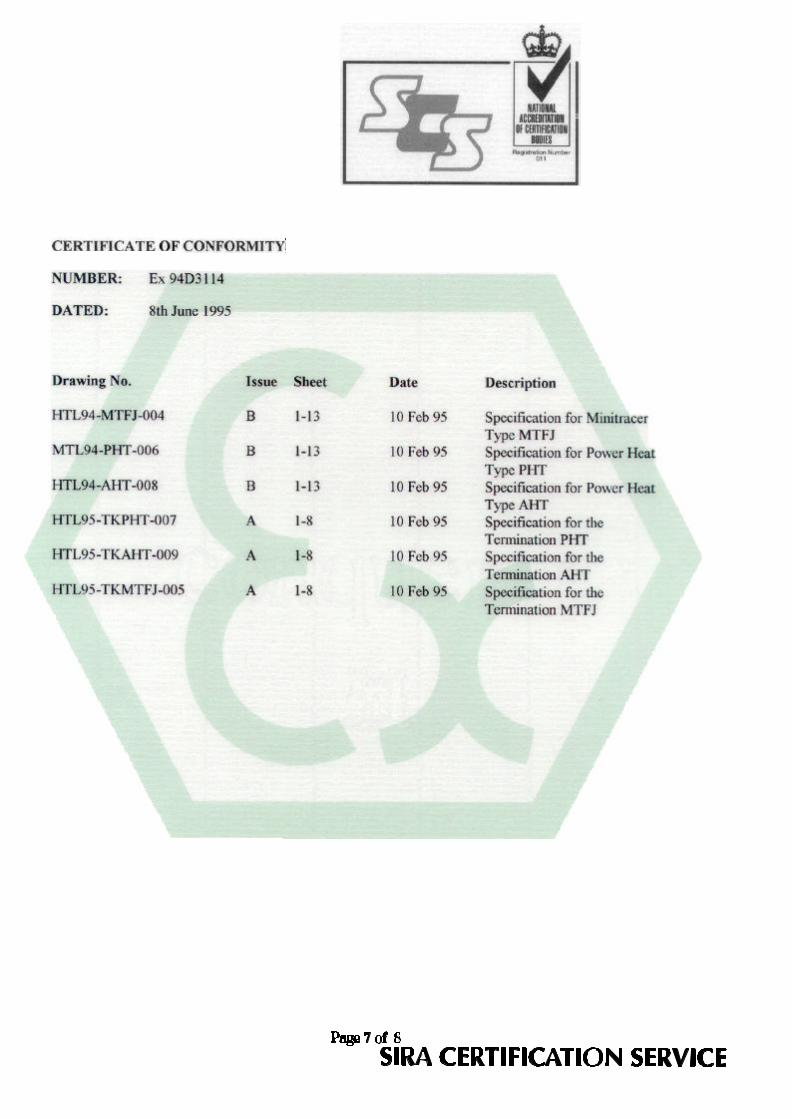
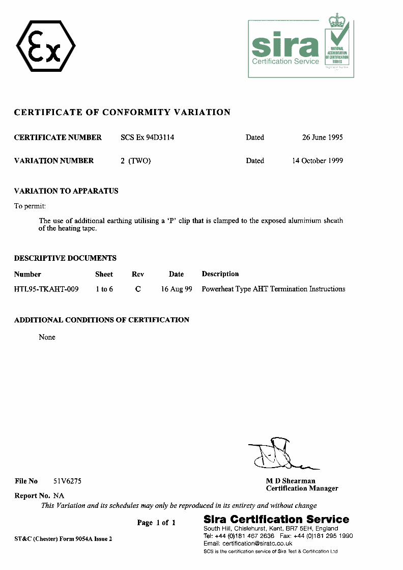
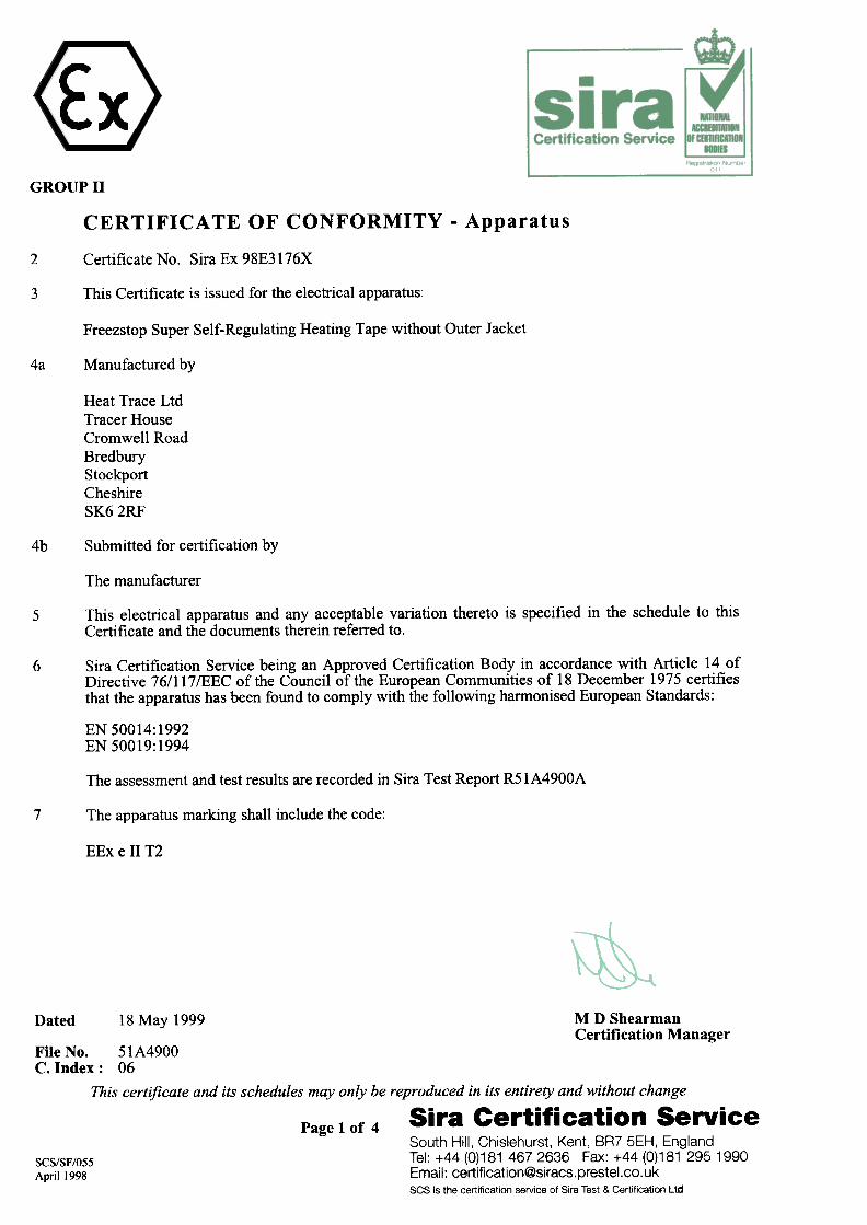
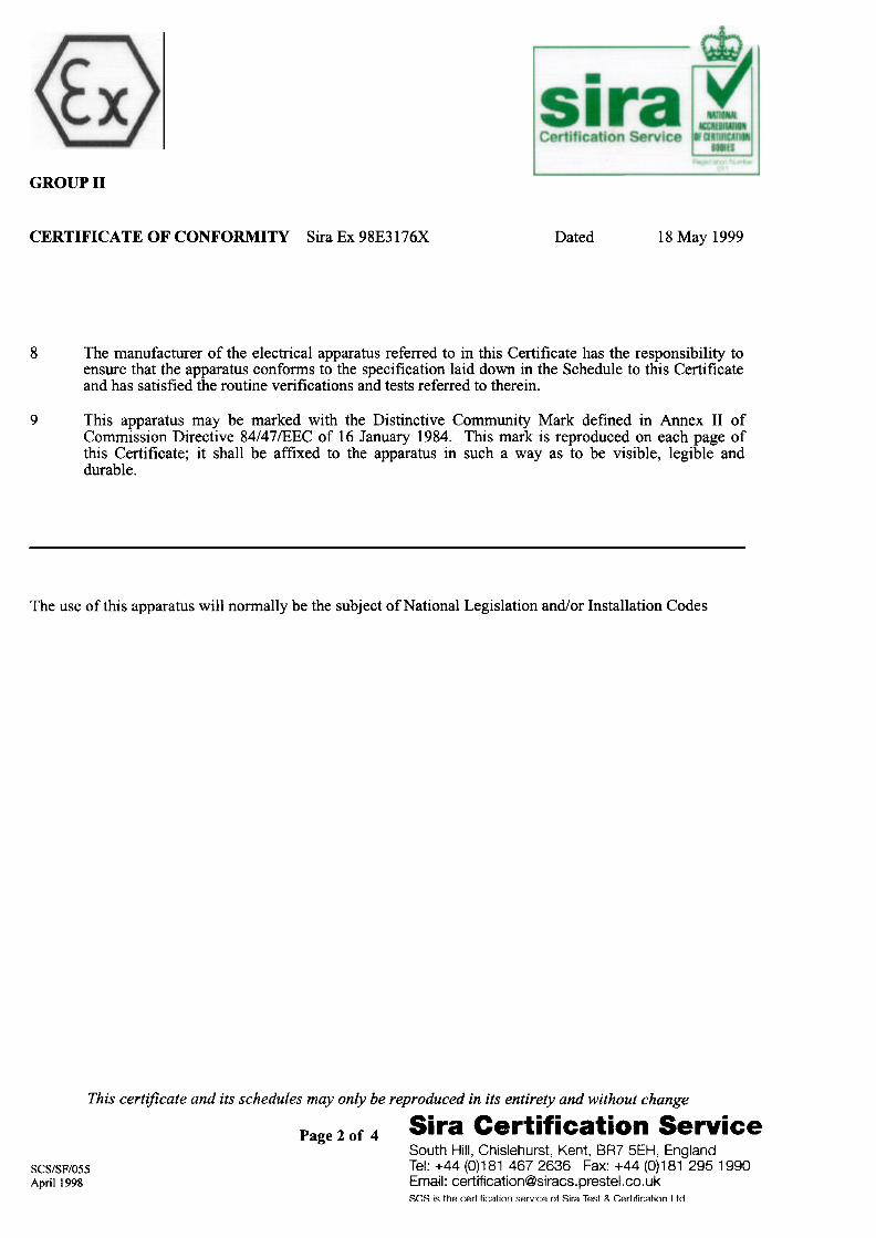
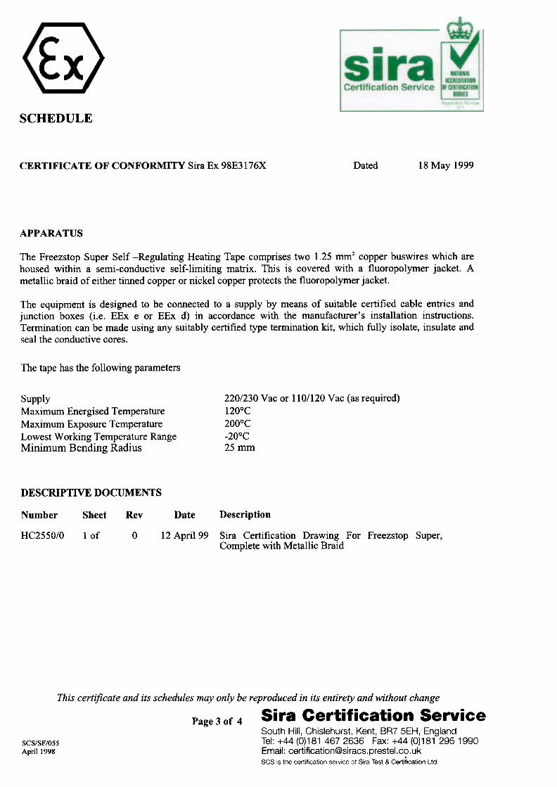
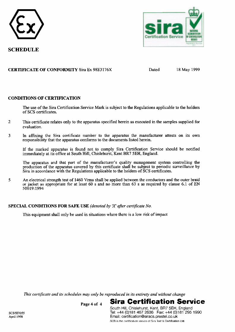
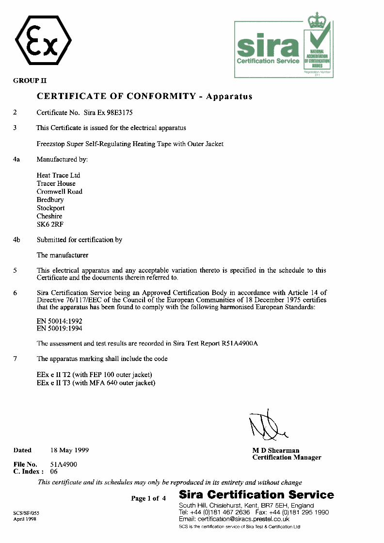
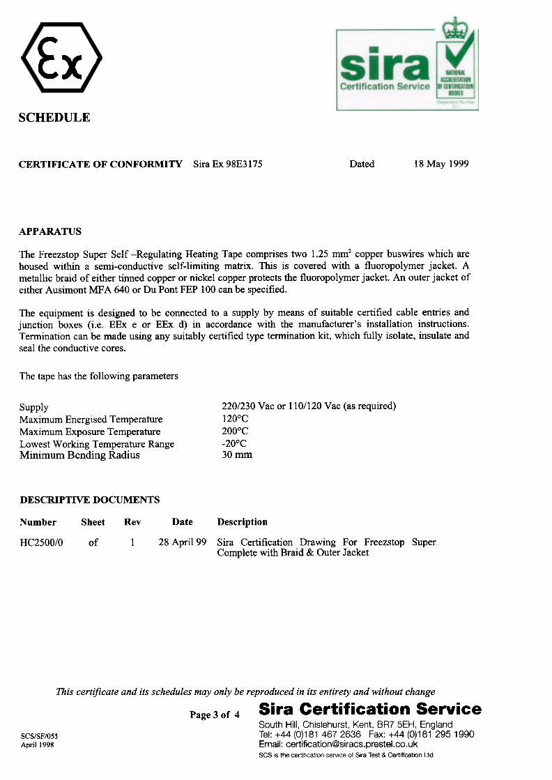
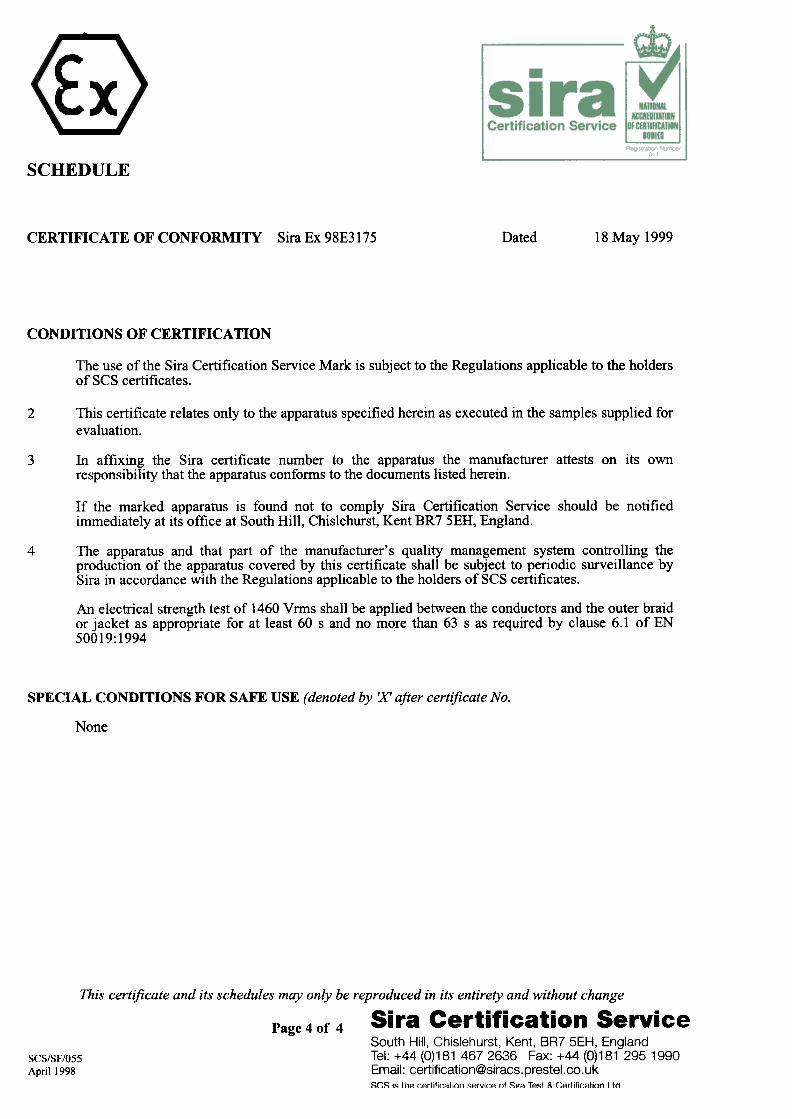
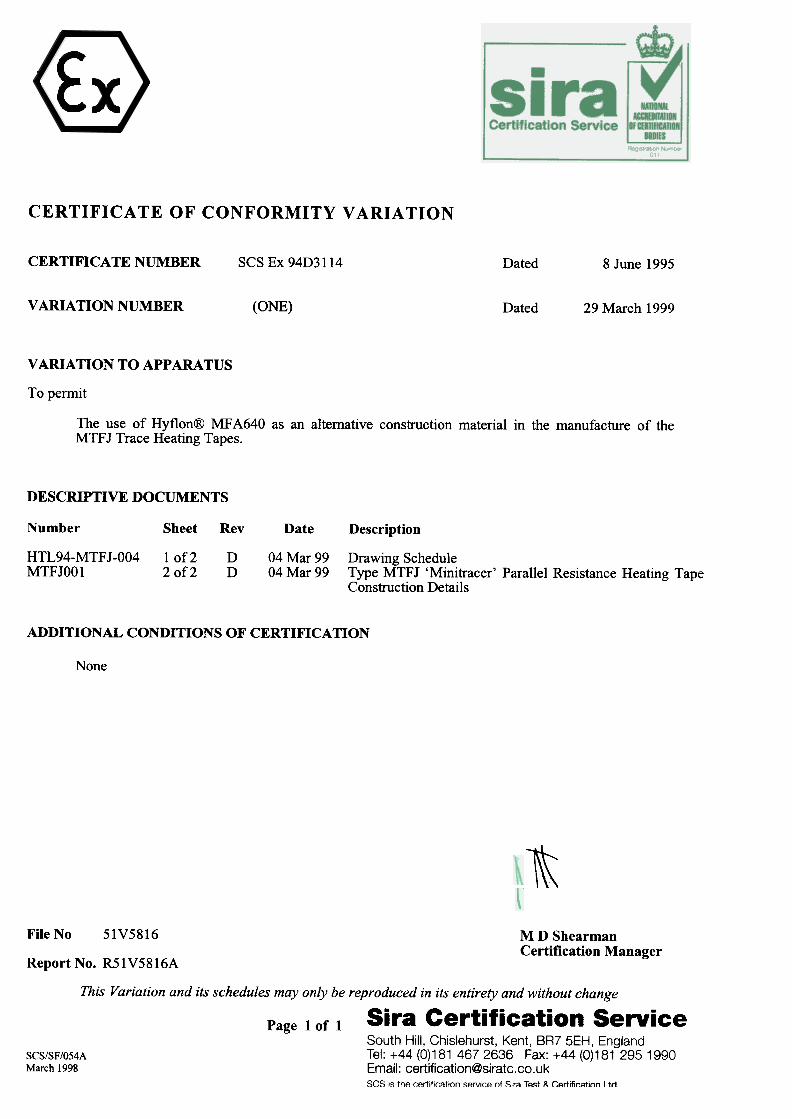
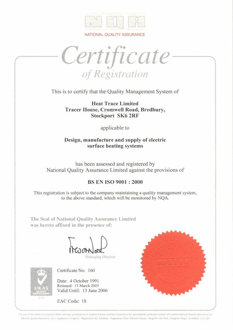
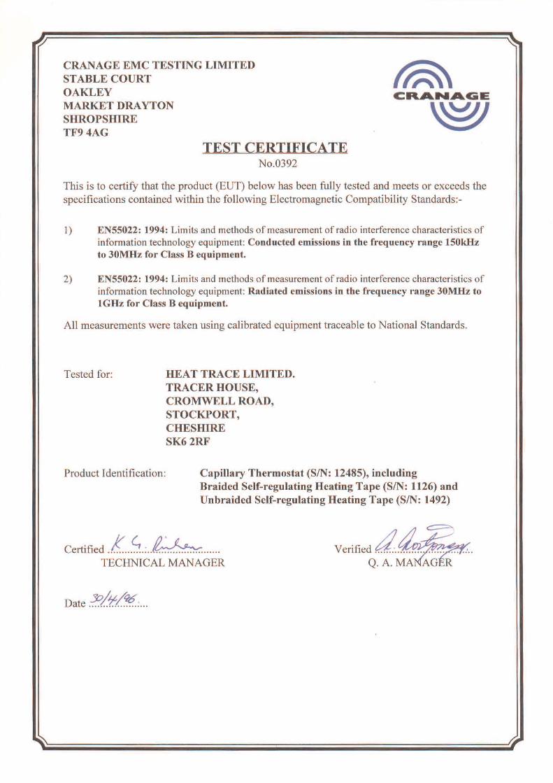
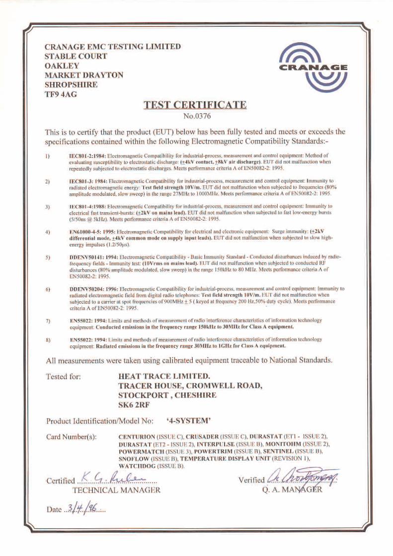
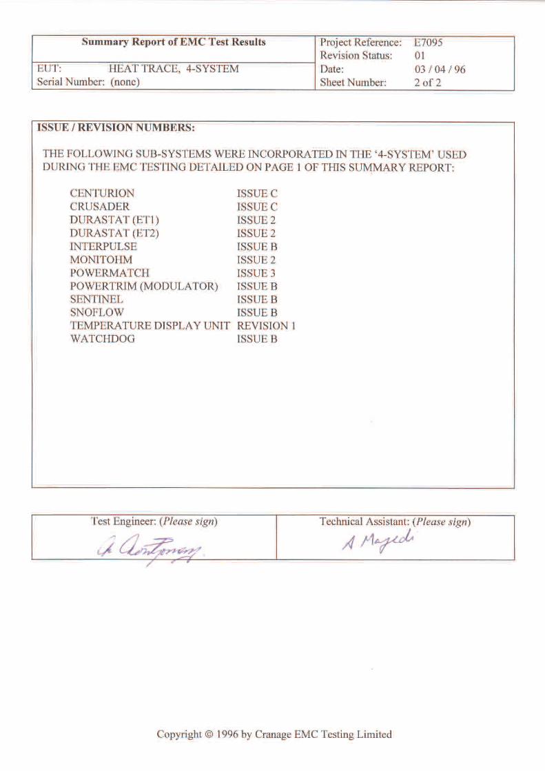

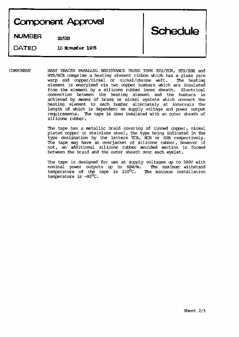
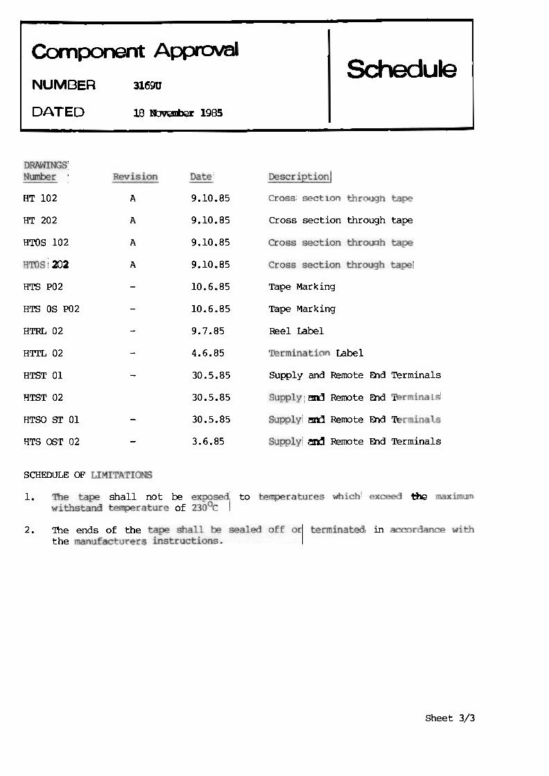
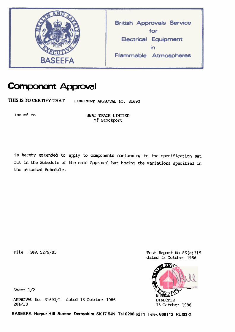
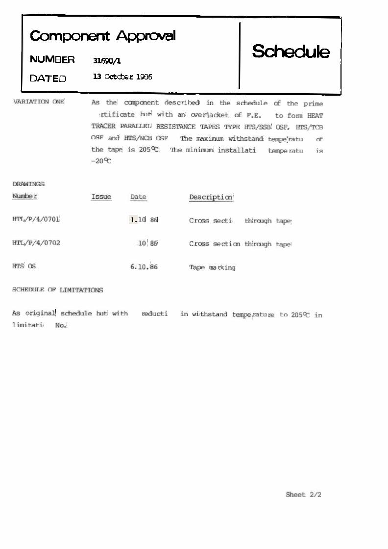
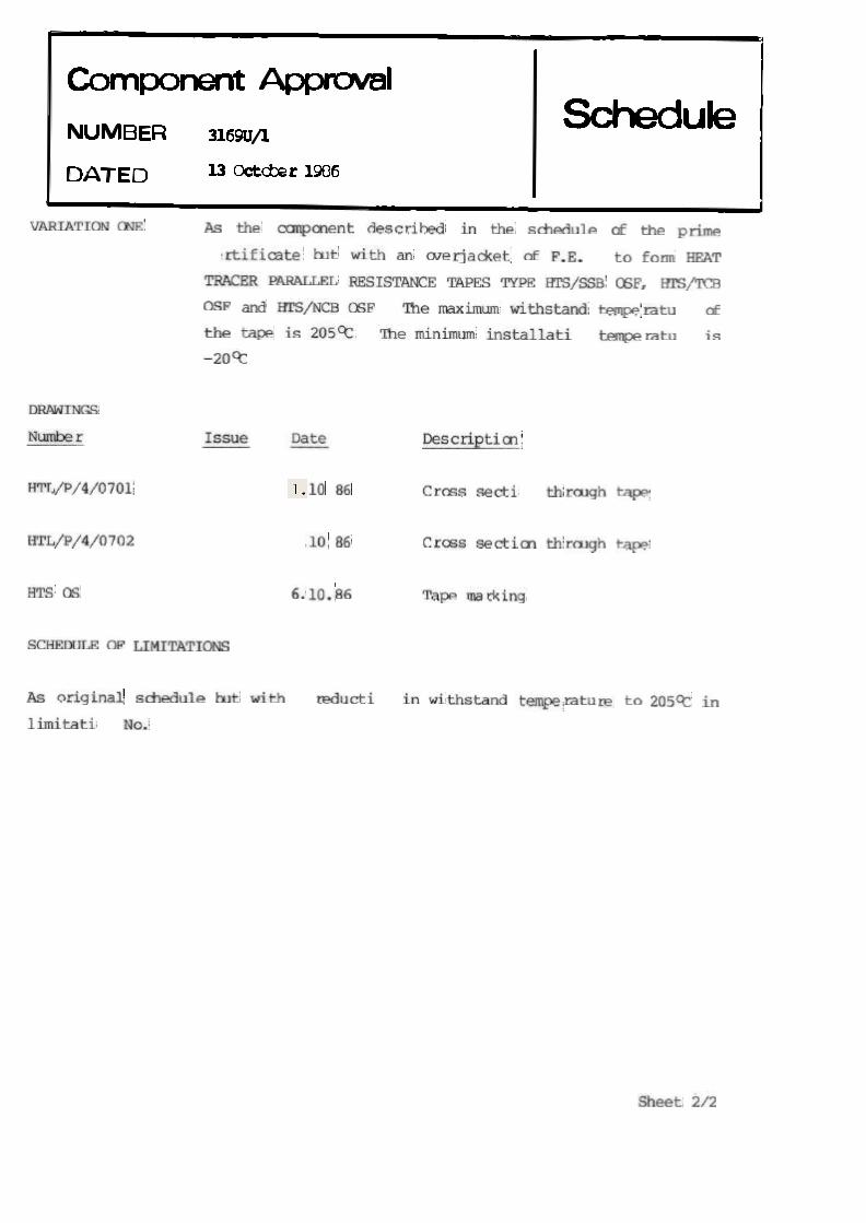
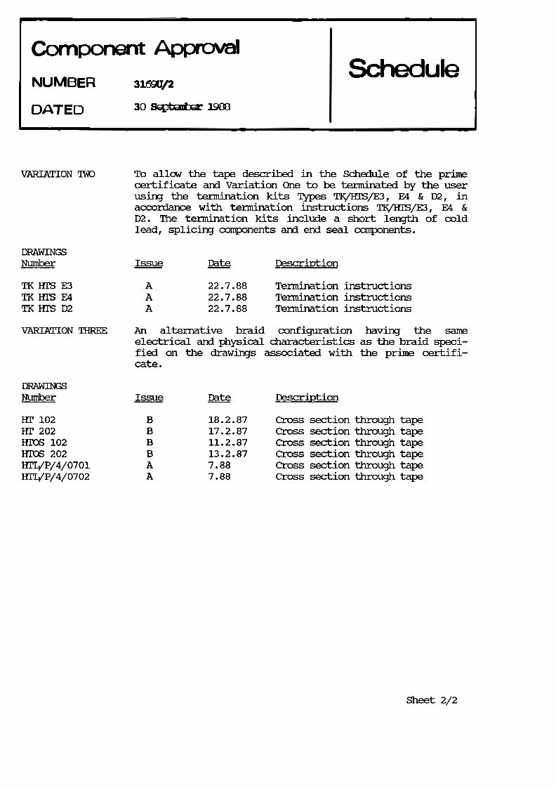
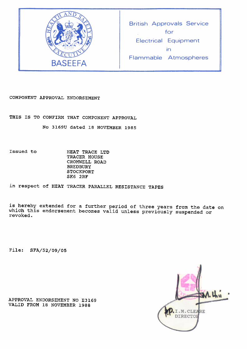
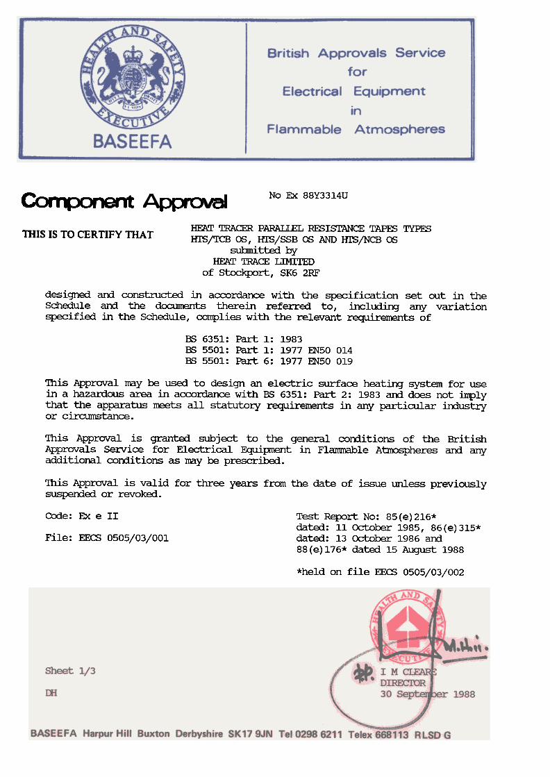
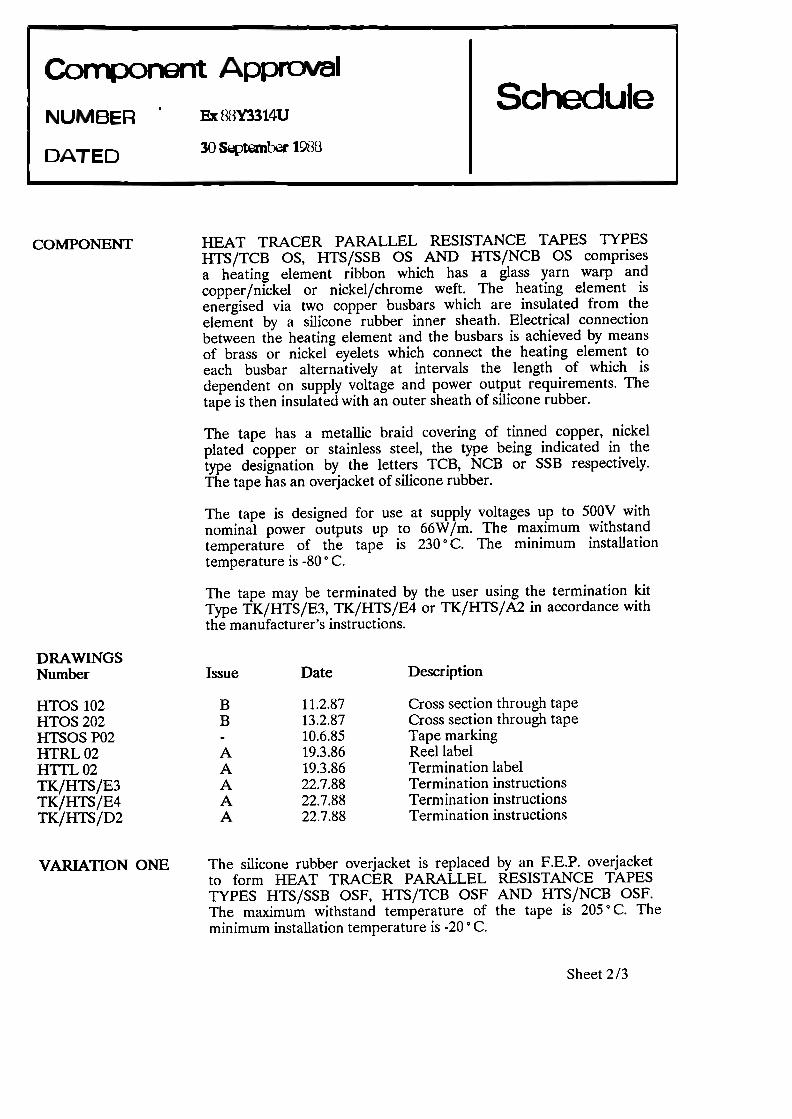
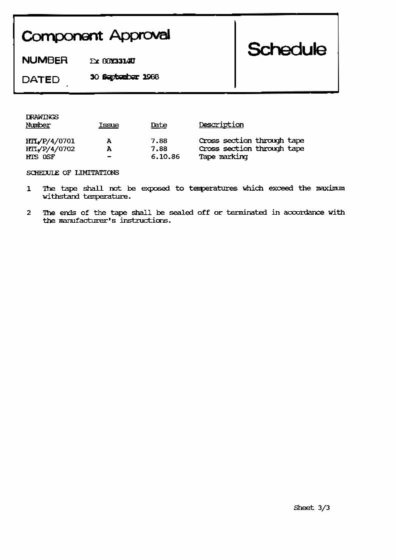
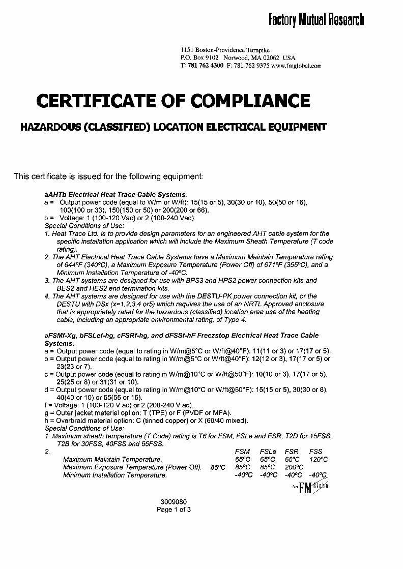
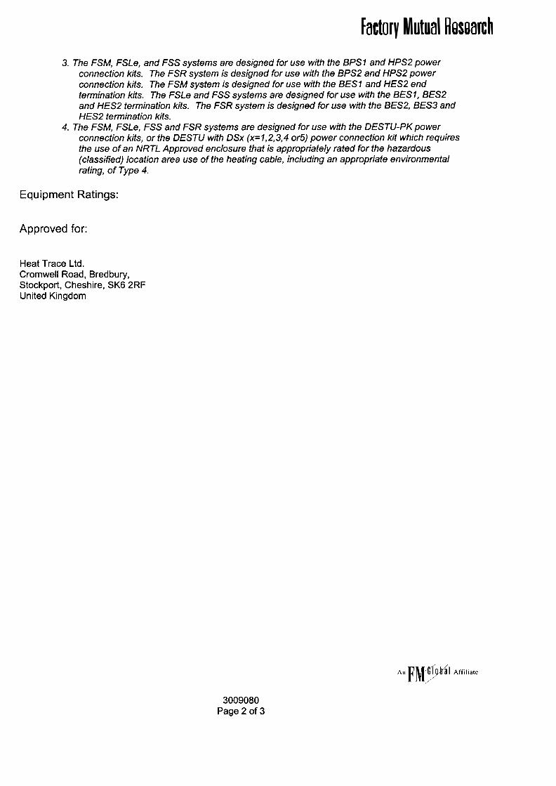
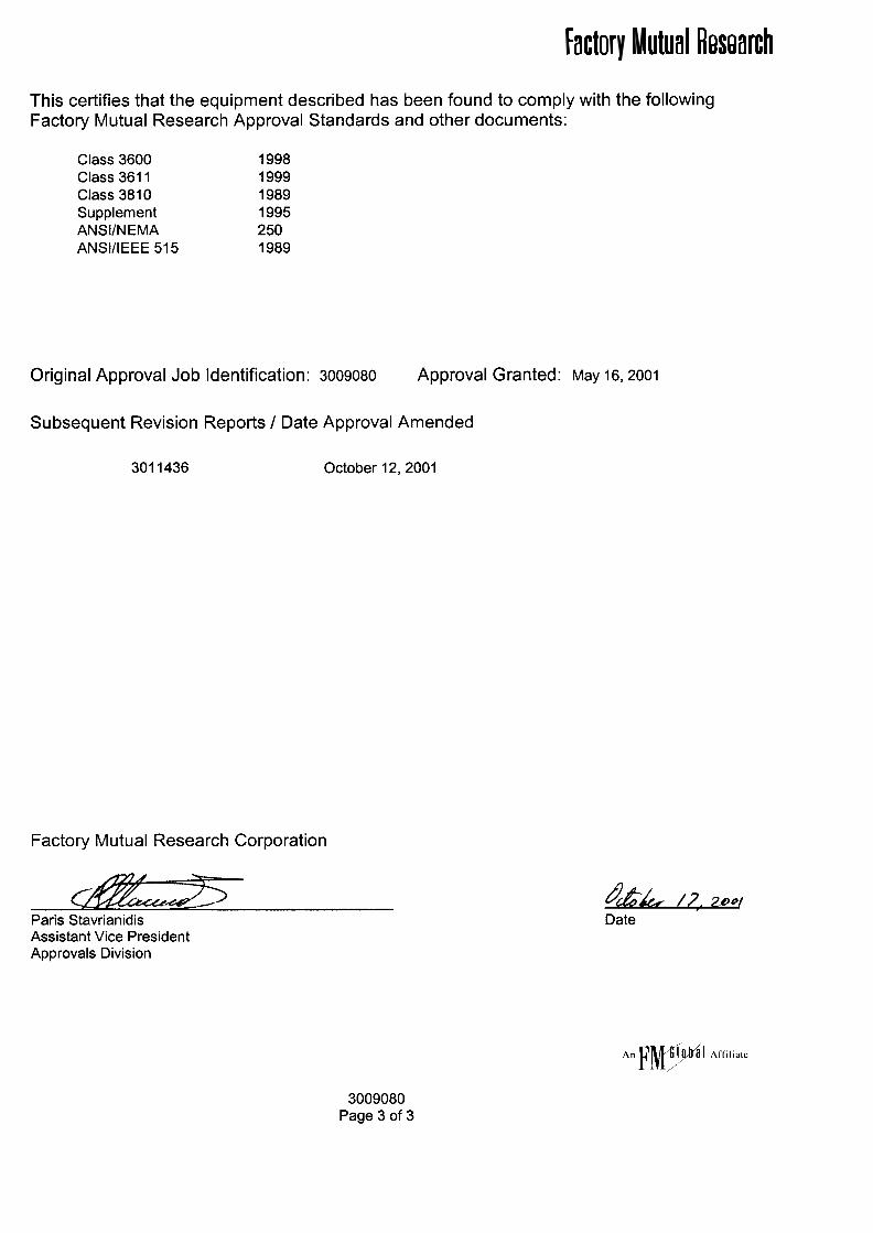
SNOMELTSelf-Regulating Snow and Ice
Prevention SystemAn LG affiliated company
SNOMELT For residential and light commercial applications
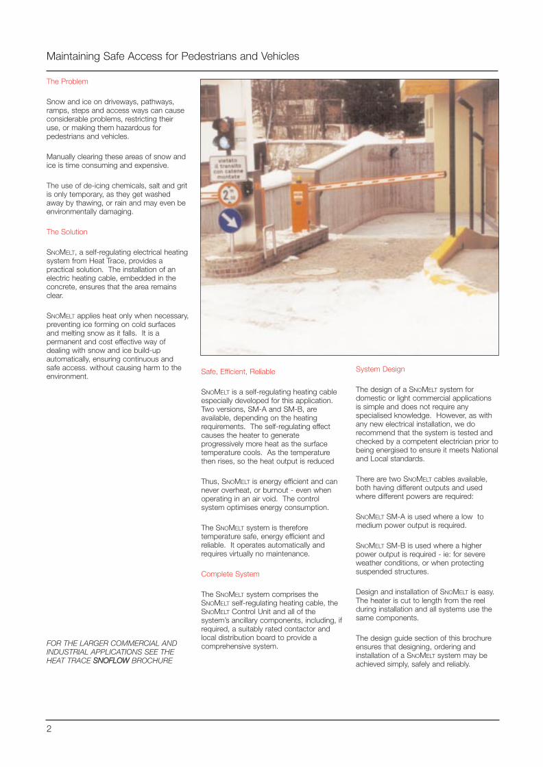
The Problem
Snow and ice on driveways, pathways,ramps, steps and access ways can causeconsiderable problems, restricting theiruse, or making them hazardous forpedestrians and vehicles.
Manually clearing these areas of snow andice is time consuming and expensive.
The use of de-icing chemicals, salt and gritis only temporary, as they get washedaway by thawing, or rain and may even beenvironmentally damaging.
The Solution
SNOMELT, a self-regulating electrical heatingsystem from Heat Trace, provides apractical solution. The installation of anelectric heating cable, embedded in theconcrete, ensures that the area remainsclear.
SNOMELT applies heat only when necessary,preventing ice forming on cold surfacesand melting snow as it falls. It is apermanent and cost effective way ofdealing with snow and ice build-upautomatically, ensuring continuous andsafe access. without causing harm to theenvironment.
Maintaining Safe Access for Pedestrians and Vehicles
FOR THE LARGER COMMERCIAL ANDINDUSTRIAL APPLICATIONS SEE THEHEAT TRACE SSNNOOFFLLOOWW BROCHURE
2
Safe, Efficient, Reliable
SNOMELT is a self-regulating heating cableespecially developed for this application.Two versions, SM-A and SM-B, areavailable, depending on the heatingrequirements. The self-regulating effectcauses the heater to generateprogressively more heat as the surfacetemperature cools. As the temperaturethen rises, so the heat output is reduced
Thus, SNOMELT is energy efficient and cannever overheat, or burnout - even whenoperating in an air void. The controlsystem optimises energy consumption.
The SNOMELT system is thereforetemperature safe, energy efficient andreliable. It operates automatically andrequires virtually no maintenance.
Complete System
The SNOMELT system comprises theSNOMELT self-regulating heating cable, theSNOMELT Control Unit and all of thesystem’s ancillary components, including, ifrequired, a suitably rated contactor andlocal distribution board to provide acomprehensive system.
System Design
The design of a SNOMELT system fordomestic or light commercial applicationsis simple and does not require anyspecialised knowledge. However, as withany new electrical installation, we dorecommend that the system is tested andchecked by a competent electrician prior tobeing energised to ensure it meets Nationaland Local standards.
There are two SNOMELT cables available,both having different outputs and usedwhere different powers are required:
SNOMELT SM-A is used where a low tomedium power output is required.
SNOMELT SM-B is used where a higherpower output is required - ie: for severeweather conditions, or when protectingsuspended structures.
Design and installation of SNOMELT is easy.The heater is cut to length from the reelduring installation and all systems use thesame components.
The design guide section of this brochureensures that designing, ordering andinstallation of a SNOMELT system may beachieved simply, safely and reliably.
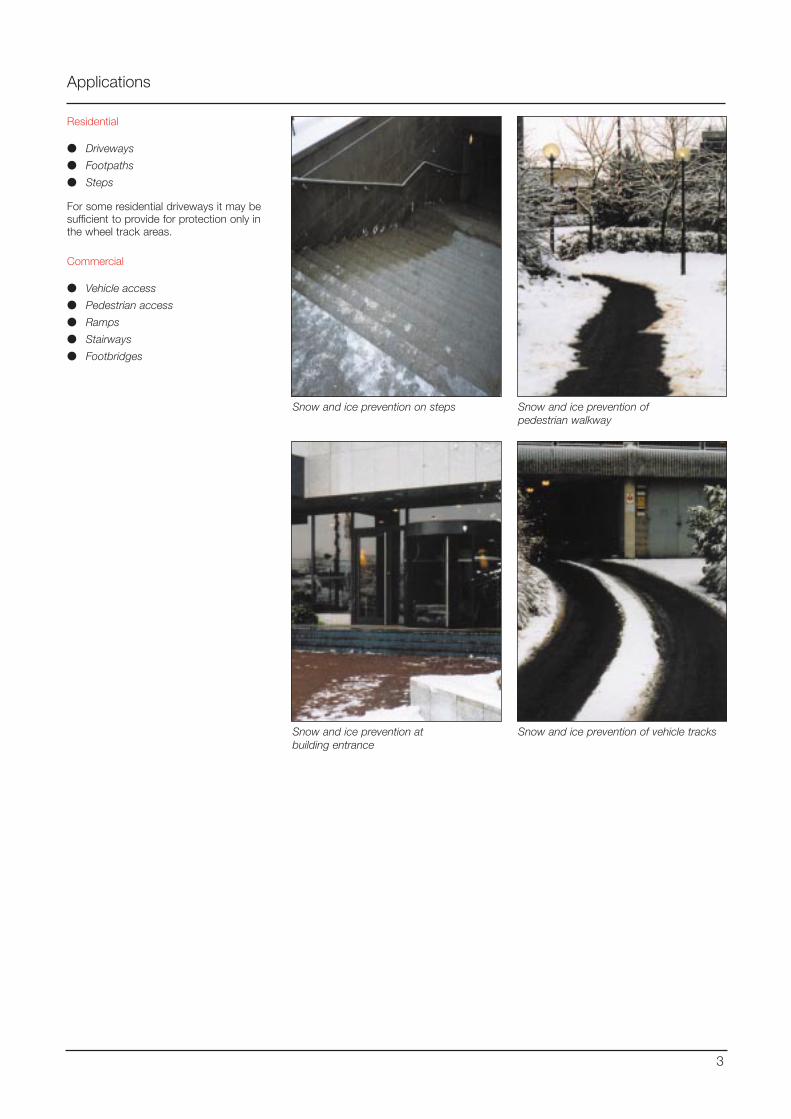
Applications
Residential
Driveways
Footpaths
Steps
For some residential driveways it may besufficient to provide for protection only inthe wheel track areas.
Commercial
Vehicle access
Pedestrian access
Ramps
Stairways
Footbridges
3
Snow and ice prevention on steps Snow and ice prevention ofpedestrian walkway
Snow and ice prevention atbuilding entrance
Snow and ice prevention of vehicle tracks
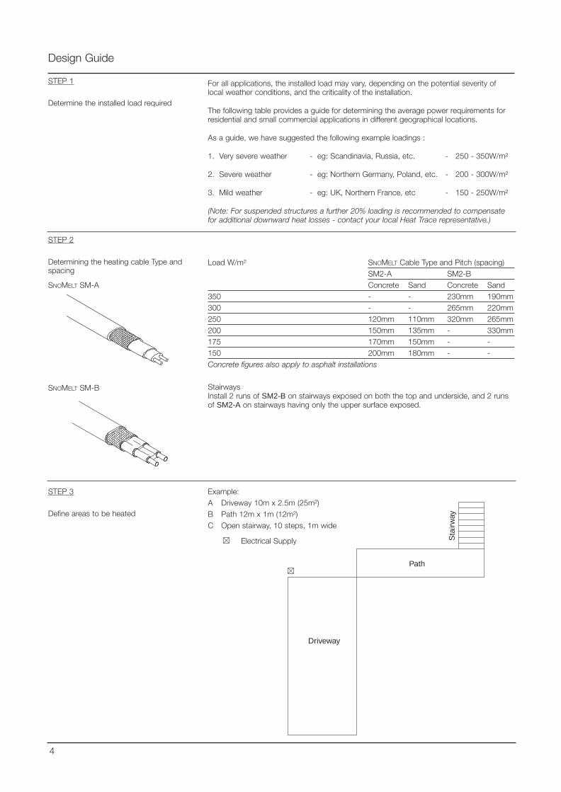
Design Guide
For all applications, the installed load may vary, depending on the potential severity oflocal weather conditions, and the criticality of the installation.
The following table provides a guide for determining the average power requirements forresidential and small commercial applications in different geographical locations.
As a guide, we have suggested the following example loadings :
1. Very severe weather - eg: Scandinavia, Russia, etc. - 250 - 350W/m²
2. Severe weather - eg: Northern Germany, Poland, etc. - 200 - 300W/m²
3. Mild weather - eg: UK, Northern France, etc - 150 - 250W/m²
(Note: For suspended structures a further 20% loading is recommended to compensatefor additional downward heat losses - contact your local Heat Trace representative.)
STEP 1
Determine the installed load required
Load W/m² SNOMELT Cable Type and Pitch (spacing)SM2-A SM2-BConcrete Sand Concrete Sand
350 - - 230mm 190mm300 - - 265mm 220mm250 120mm 110mm 320mm 265mm200 150mm 135mm - 330mm175 170mm 150mm - -150 200mm 180mm - -Concrete figures also apply to asphalt installations
STEP 2
Determining the heating cable Type andspacing
STEP 3
Define areas to be heated
Driveway
Path
Sta
irway
Electrical Supply
SNOMELT SM-A
SNOMELT SM-B
4
Example:A Driveway 10m x 2.5m (25m²)B Path 12m x 1m (12m²)C Open stairway, 10 steps, 1m wide
StairwaysInstall 2 runs of SM2-B on stairways exposed on both the top and underside, and 2 runsof SM2-A on stairways having only the upper surface exposed.
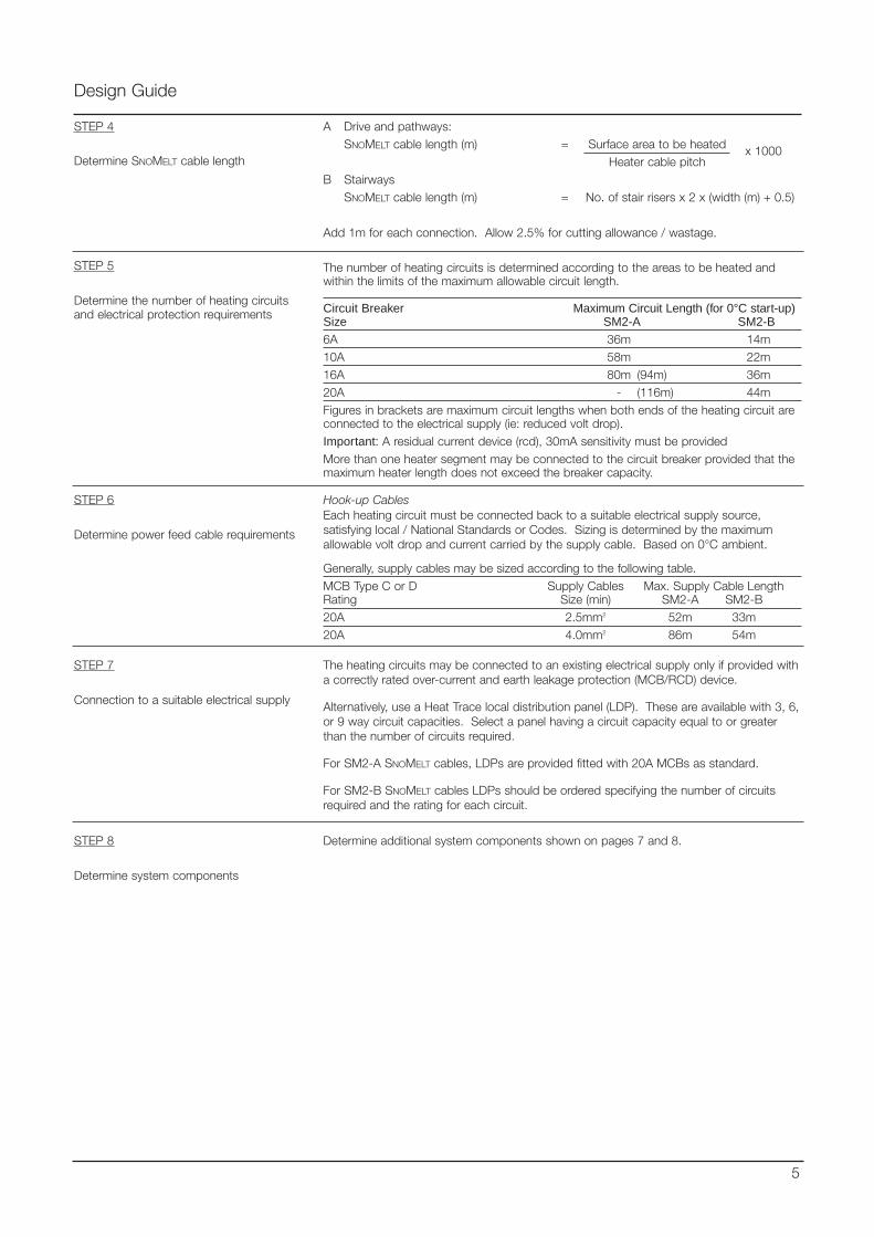
The number of heating circuits is determined according to the areas to be heated andwithin the limits of the maximum allowable circuit length.
Circuit Breaker Maximum Circuit Length (for 0°C start-up)Size SM2-A SM2-B
6A 36m 14m10A 58m 22m16A 80m (94m) 36m20A - (116m) 44mFigures in brackets are maximum circuit lengths when both ends of the heating circuit areconnected to the electrical supply (ie: reduced volt drop).Important: A residual current device (rcd), 30mA sensitivity must be providedMore than one heater segment may be connected to the circuit breaker provided that themaximum heater length does not exceed the breaker capacity.
Design Guide
STEP 5
Determine the number of heating circuitsand electrical protection requirements
STEP 6
Determine power feed cable requirements
Hook-up CablesEach heating circuit must be connected back to a suitable electrical supply source,satisfying local / National Standards or Codes. Sizing is determined by the maximumallowable volt drop and current carried by the supply cable. Based on 0°C ambient.
Generally, supply cables may be sized according to the following table.MCB Type C or D Supply Cables Max. Supply Cable LengthRating Size (min) SM2-A SM2-B20A 2.5mm2 52m 33m20A 4.0mm2 86m 54m
STEP 4
Determine SNOMELT cable length
A Drive and pathways:SNOMELT cable length (m) = Surface area to be heated
Heater cable pitchB Stairways
SNOMELT cable length (m) = No. of stair risers x 2 x (width (m) + 0.5)
Add 1m for each connection. Allow 2.5% for cutting allowance / wastage.
STEP 7
Connection to a suitable electrical supply
5
The heating circuits may be connected to an existing electrical supply only if provided witha correctly rated over-current and earth leakage protection (MCB/RCD) device.
Alternatively, use a Heat Trace local distribution panel (LDP). These are available with 3, 6,or 9 way circuit capacities. Select a panel having a circuit capacity equal to or greaterthan the number of circuits required.
For SM2-A SNOMELT cables, LDPs are provided fitted with 20A MCBs as standard.
For SM2-B SNOMELT cables LDPs should be ordered specifying the number of circuitsrequired and the rating for each circuit.
x 1000
STEP 8
Determine system components
Determine additional system components shown on pages 7 and 8.
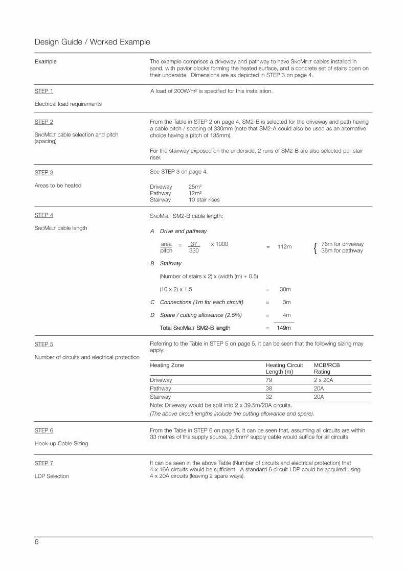
The example comprises a driveway and pathway to have SNOMELT cables installed insand, with pavior blocks forming the heated surface, and a concrete set of stairs open ontheir underside. Dimensions are as depicted in STEP 3 on page 4.
Design Guide / Worked Example
Example
STEP 1
Electrical load requirements
A load of 200W/m² is specified for this installation.
STEP 2
SNOMELT cable selection and pitch(spacing)
From the Table in STEP 2 on page 4, SM2-B is selected for the driveway and path havinga cable pitch / spacing of 330mm (note that SM2-A could also be used as an alternativechoice having a pitch of 135mm).
For the stairway exposed on the underside, 2 runs of SM2-B are also selected per stairriser.
STEP 3
Areas to be heated
See STEP 3 on page 4.
Driveway 25m²Pathway 12m²Stairway 10 stair rises
STEP 4
SNOMELT cable length
SNOMELT SM2-B cable length:
A Drive and pathway
area 37 x 1000 76m for drivewaypitch 330 36m for pathway
B Stairway
(Number of stairs x 2) x (width (m) + 0.5)
(10 x 2) x 1.5 = 30m
C Connections (1m for each circuit) = 3m
D Spare / cutting allowance (2.5%) = 4m
TToottaall SSNNOOMMEELLTT SSMM22--BB lleennggtthh == 114499mm
= = 112m
STEP 5
Number of circuits and electrical protection
Referring to the Table in STEP 5 on page 5, it can be seen that the following sizing mayapply:
Heating Zone Heating Circuit MCB/RCBLength (m) Rating
Driveway 79 2 x 20A
Pathway 38 20A
Stairway 32 20A
Note: Driveway would be split into 2 x 39.5m/20A circuits.
(The above circuit lengths include the cutting allowance and spare).
STEP 6
Hook-up Cable Sizing
From the Table in STEP 6 on page 5, it can be seen that, assuming all circuits are within33 metres of the supply source, 2.5mm² supply cable would suffice for all circuits
STEP 7
LDP Selection
It can be seen in the above Table (Number of circuits and electrical protection) that4 x 16A circuits would be sufficient. A standard 6 circuit LDP could be acquired using4 x 20A circuits (leaving 2 spare ways).
6
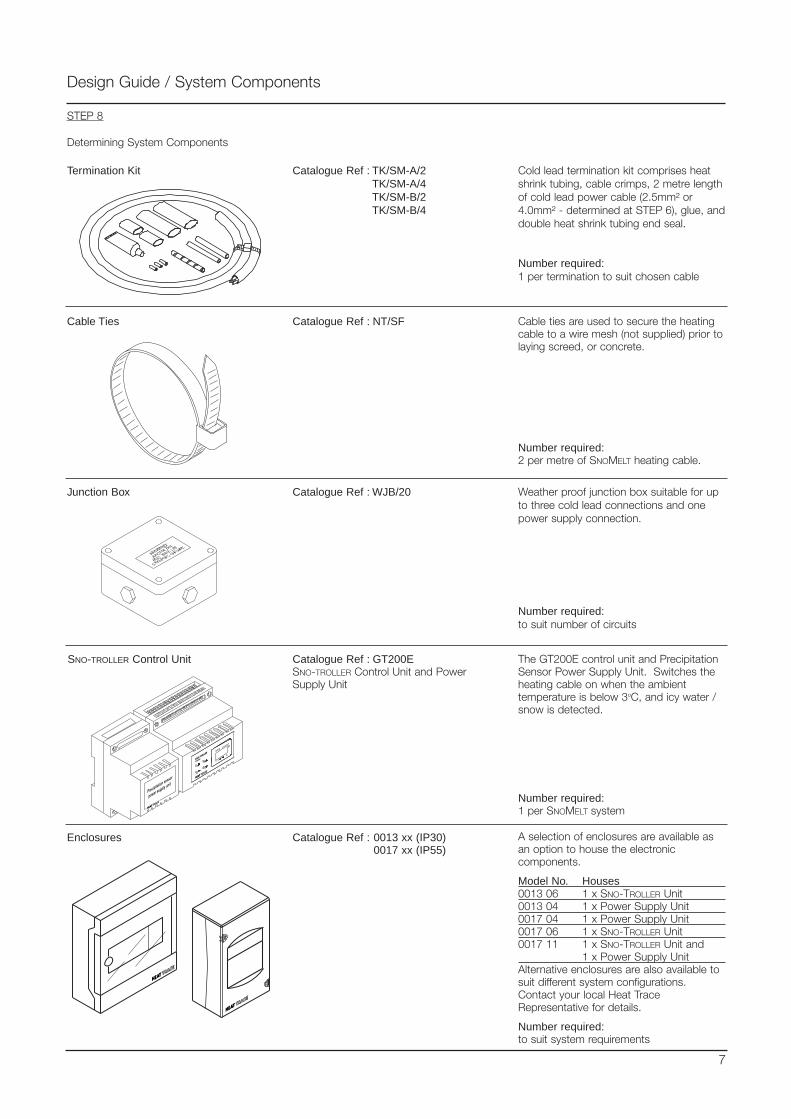
Design Guide / System Components
Catalogue Ref : GT200ESNO-TROLLER Control Unit and PowerSupply Unit
The GT200E control unit and PrecipitationSensor Power Supply Unit. Switches theheating cable on when the ambienttemperature is below 3oC, and icy water /snow is detected.
Number required:1 per SNOMELT system
SNO-TROLLER Control Unit
Termination Kit Cold lead termination kit comprises heatshrink tubing, cable crimps, 2 metre lengthof cold lead power cable (2.5mm² or4.0mm² - determined at STEP 6), glue, anddouble heat shrink tubing end seal.
Number required:1 per termination to suit chosen cable
Catalogue Ref : TK/SM-A/2 TK/SM-A/4TK/SM-B/2TK/SM-B/4
Catalogue Ref : WJB/20 Weather proof junction box suitable for upto three cold lead connections and onepower supply connection.
Number required:to suit number of circuits
Junction Box
7
Enclosures Catalogue Ref : 0013 xx (IP30)0017 xx (IP55)
A selection of enclosures are available asan option to house the electroniccomponents.
Model No. Houses0013 06 1 x SNO-TROLLER Unit0013 04 1 x Power Supply Unit0017 04 1 x Power Supply Unit0017 06 1 x SNO-TROLLER Unit0017 11 1 x SNO-TROLLER Unit and
1 x Power Supply UnitAlternative enclosures are also available tosuit different system configurations.Contact your local Heat TraceRepresentative for details.
Number required:to suit system requirements
Cable Ties Catalogue Ref : NT/SF Cable ties are used to secure the heatingcable to a wire mesh (not supplied) prior tolaying screed, or concrete.
Number required:2 per metre of SNOMELT heating cable.
STEP 8
Determining System Components

Design Guide / System Components
The distribution panel is selected according to the number of circuits calculated at STEP 5.Each panel is provided with a 20A circuit breaker for each outgoing circuit. A ground faultprotection device is fitted, sensitivity 30mA, 30ms for protection of all circuits. The LDP isalso provided with a main incoming isolator.Standard panels are:
LDP-03/20 for up to 3 x 20A, 230V circuits, single phase incoming feed.LDP-06/20 for up to 6 x 20A, 230V circuits, 3 phase & neutral incoming feed.LDP-09/20 for up to 9 x 20A, 230V circuits, 3 phase & neutral incoming feed.
The LDP is rated IP54 for internal use. It should therefore be suitably weather protected ifinstalled outdoors.
Above LDPs are suitable for use with 115 VAC or 230 VAC supplies.
32A Contactor box for up to 6 circuits (or more if the start up load does not exceed 32Aon each of 3 phases. The C32/1 (110V), and C32/2 (230V) units comprise a plasticenclosure 190 x 150 x 85mm incorporating the contactor. Used in conjunction with LDP.
63A Contactor box for up to 12 circuits. The start up load should not exceed 63A on eachof 3 phases. The C63/1 (110V), and C63/2 (230V) units comprise a plastic enclosure190 x 150 x 85mm incorporating the contactor. Used in conjunction with LDP.
Number required:1 per SNOMELT system
Contactor Box
Local Distribution Panel (LDP)
8
Sensors Catalogue Ref : GT200E/SSNOMELT Sensor Pack
The SNOMELT snow sensor is suppliedcomplete with a 3.5m flexible conduit forrouting to the GT200E Snow Control Unit.Connection may be made directly into theGT200E unit, or remotely via a suitablecable and conduit provided by the installer.
The SNOMELT temperature sensor isprovided in the same kit. Additionalconduit length from the GT200E unit to thesensor should be provided by the installer.
Number required:1 per SNOMELT system
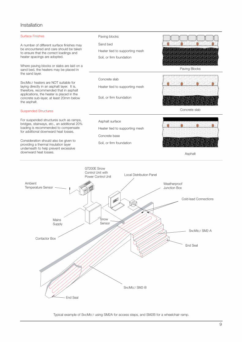
Installation
9
WEATHERPROOF
JUNCTION BOX
HEAT TRACE LTD
STOCKPORT, CHESHIRE
Typical example of SNOMELT using SM2A for access steps, and SM2B for a wheelchair ramp.
Surface Finishes
A number of different surface finishes maybe encountered and care should be takento ensure that the correct loadings andheater spacings are adopted.
Where paving blocks or slabs are laid on asand bed, the heaters may be placed inthe sand layer.
SNOMELT heaters are NOT suitable forlaying directly in an asphalt layer. It is,therefore, recommended that in asphaltapplications, the heater is placed in theconcrete sub-layer, at least 20mm belowthe asphalt.
Suspended Structures
For suspended structures such as ramps,bridges, stairways, etc., an additional 20%loading is recommended to compensatefor additional downward heat losses.
Consideration should also be given toproviding a thermal insulation layerunderneath to help prevent excessivedownward heat losses.
Paving Blocks
Concrete slab
Asphalt
Paving blocks
Sand bed
Heater tied to supporting mesh
Soil, or firm foundation
Concrete slab
Heater tied to supporting mesh
Soil, or firm foundation
Asphalt surface
Heater tied to supporting mesh
Concrete base
Soil, or firm foundation
Contactor Box
Local Distribution Panel
WeatherproofJunction Box
GT200E SnowControl Unit withPower Control Unit
AmbientTemperature Sensor
SnowSensor
End Seal
End Seal
SNOMELT SM2-B
SNOMELT SM2-A
Cold-lead Connections
MainsSupply
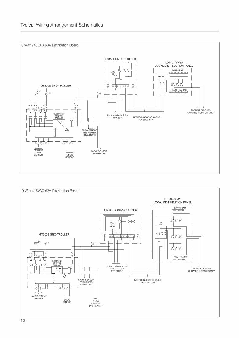
Typical Wiring Arrangement Schematics
3 Way 240VAC 63A Distribution Board
9 Way 415VAC 63A Distribution Board
10
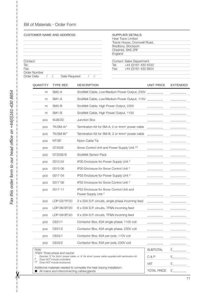
Bill of Materials - Order Form
Fa
x th
is o
rder
form
to o
ur h
ead
offic
e on
+44
(0)1
61-4
30 8
654
QUANTITY TYPE REF. DESCRIPTION UNIT PRICE EXTENDED
m SM2-A SnoMelt Cable, Low/Medium Power Output, 230V __________ __________
m SM1-A SnoMelt Cable, Low/Medium Power Output, 115V __________ __________
m SM2-B SnoMelt Cable, High Power Output, 230V __________ __________
m SM1-B SnoMelt Cable, High Power Output, 115V __________ __________
pcs WJB/20 Junction Box __________ __________
pcs TK/SM-A/* Termination Kit for SM-A, 2 or 4mm2 power cable __________ __________
pcs TK/SM-B/* Termination Kit for SM-B, 2 or 4mm2 power cable __________ __________
pcs NT/SF Nylon Cable Tie __________ __________
pcs GT200E Snow Control Unit and Power Supply Unit †† __________ __________
pcs GT200E/S SnoMelt Sensor Pack __________ __________
pcs 0013 04 IP30 Enclosure for Power Supply Unit † __________ __________
pcs 0013 06 IP30 Enclosure for Snow Control Unit † __________ __________
pcs 0017 04 IP55 Enclosure for Power Supply Unit † __________ __________
pcs 0017 06 IP55 Enclosure for Snow Control Unit † __________ __________
pcs 0017 11 IP55 Enclosure for Snow Control Unit andPower Supply Unit † __________ __________
pcs LDP-03/1P/20 3 x 20A S.P. circuits, single phase incoming feed __________ __________
pcs LDP-06/3P/20 6 x 20A S.P. circuits, TP&N incoming feed __________ __________
pcs LDP-09/3P/20 9 x 20A S.P. circuits, TP&N incoming feed __________ __________
pcs C631/1 Contactor Box, 63A single phase, 110V coil __________ __________
pcs C631/2 Contactor Box, 63A single phase, 230V coil __________ __________
pcs C633/1 Contactor Box, 63A per pole, 110V coil __________ __________
pcs C633/2 Contactor Box, 63A per pole, 230V coil __________ __________
SUBTOTAL £_________
C & P £_________
VAT £_________
TOTAL PRICE £_________
CUSTOMER NAME AND ADDRESS:
Contact:Tel:Fax:Order NumberOrder Date / / Date Required / /
SUPPLIER DETAILS:Heat Trace LimitedTracer House, Cromwell Road,Bredbury, StockportCheshire, SK6 2RFEngland
Contact: Sales DepartmentTel: +44 (0)161 430 8333Fax: +44 (0)161 430 8654
11
Note:TP&N: Three phase and neutral* Denotes ‘2’ for 2mm2 power cable, or ‘4’ for 4mm2 power cable supplied with termination kit† Does NOT include controllers†† Does NOT include enclosures
Additional materials needed to complete the heat tracing installation: All mains and interconnecting cables/glands

Tracer House, Cromwell Road, Bredbury, Stockport, Cheshire, SK6 2RF, U.K.Tel: +44(0)161-430 8333 Fax: +44(0)161-430 8654 http://www.heat-trace.com
The information given herein, including drawings, illustrations and schematics (which are intended for illustration purposes only), is believed to be reliable. However, Heat Trace Ltd makes nowarranties as to its accuracy or completeness and disclaims any liability in connection with its use. Users of Heat Trace Ltd products should make their own evaluation to determine the suitabilityof each such product for specific applications. In no way will Heat Trace Ltd be liable for any damages arising out of the misuse, resale or use of the product.
PD
G05
0 04
/01
Presented by:

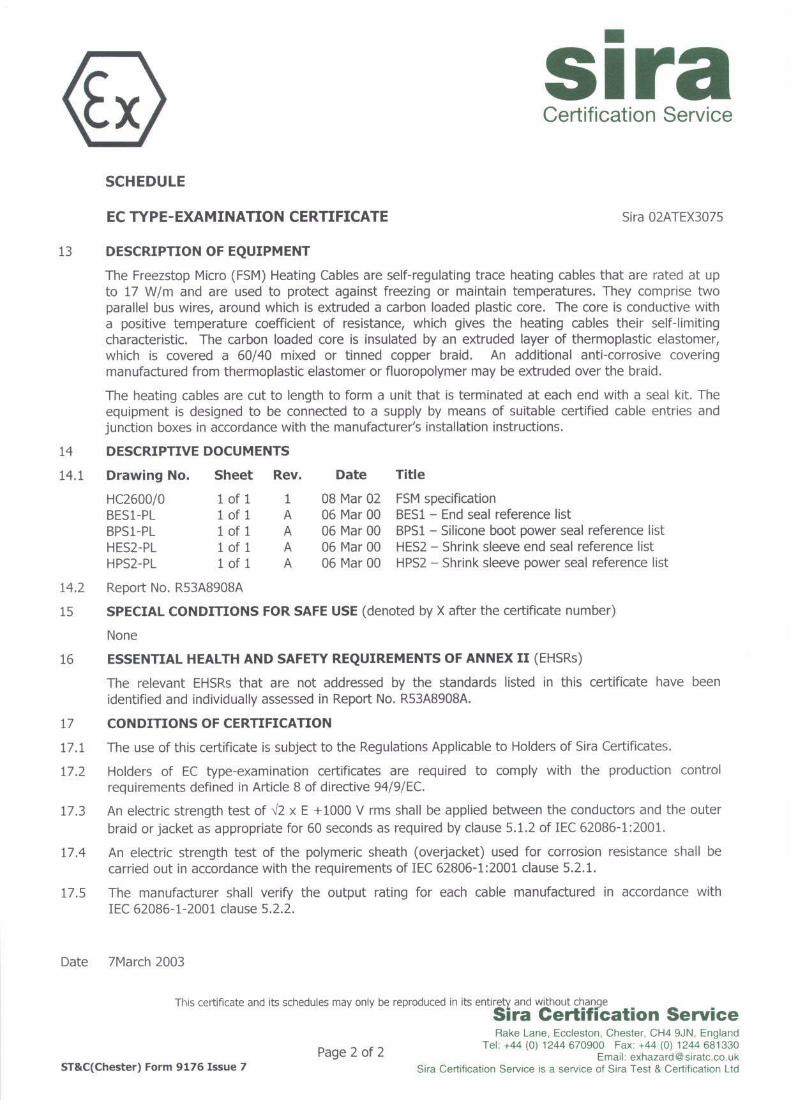
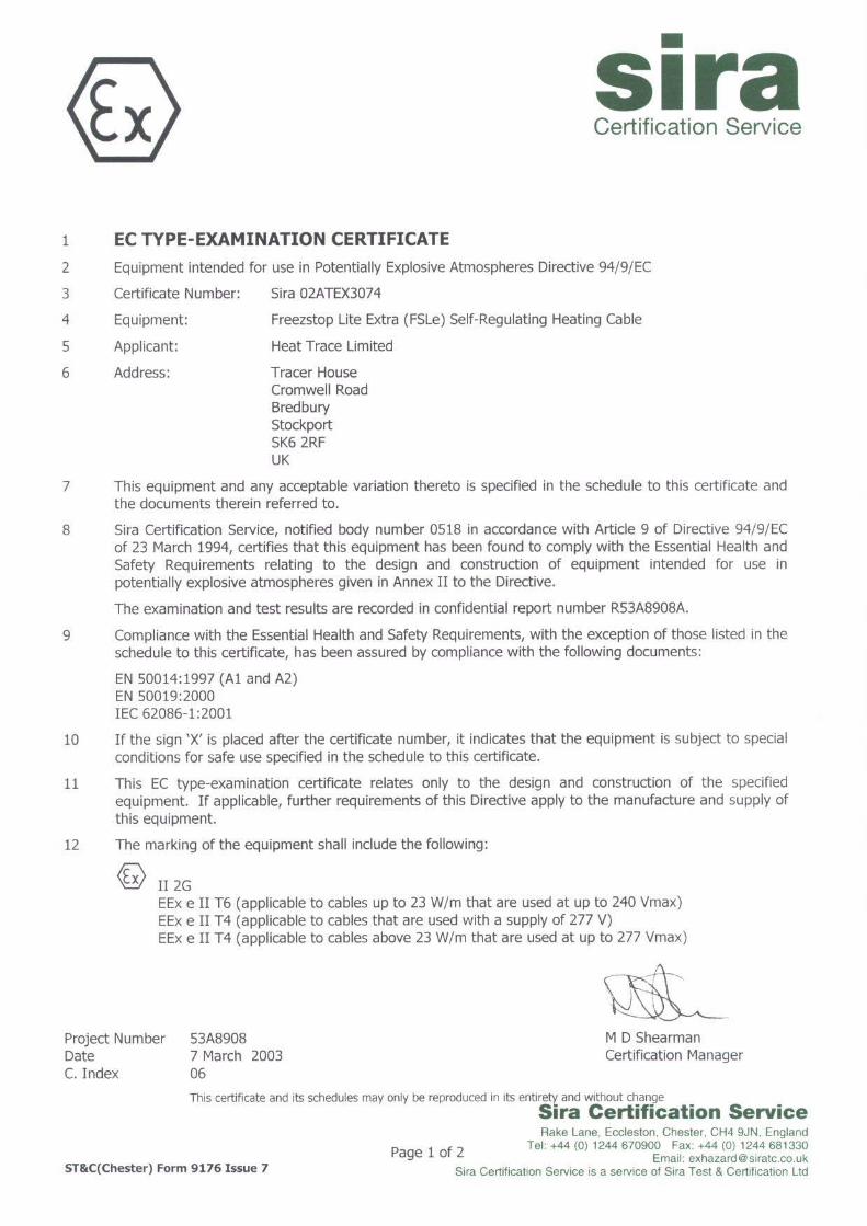
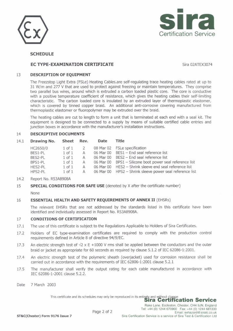
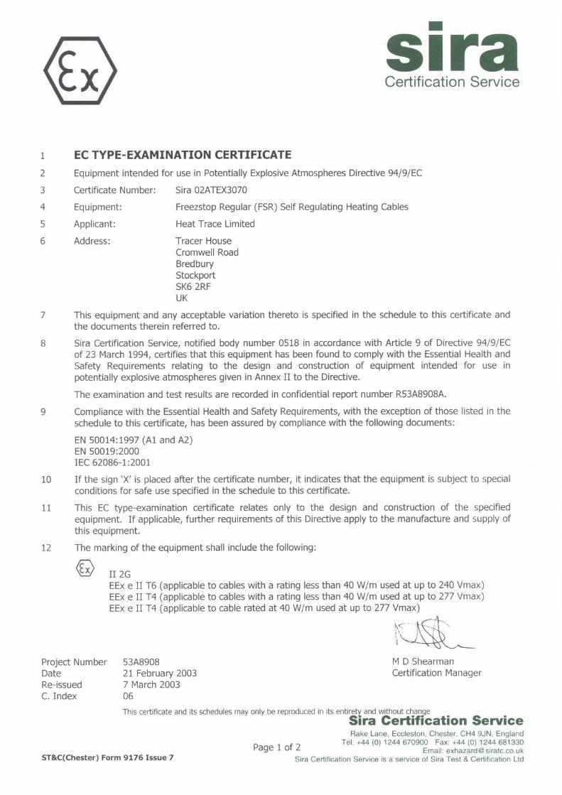
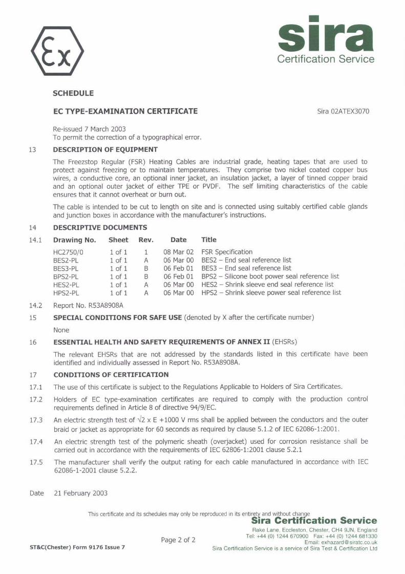

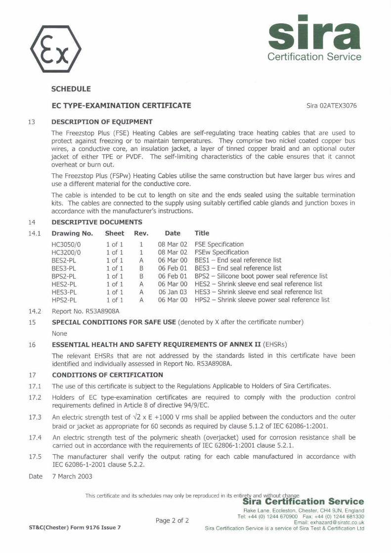
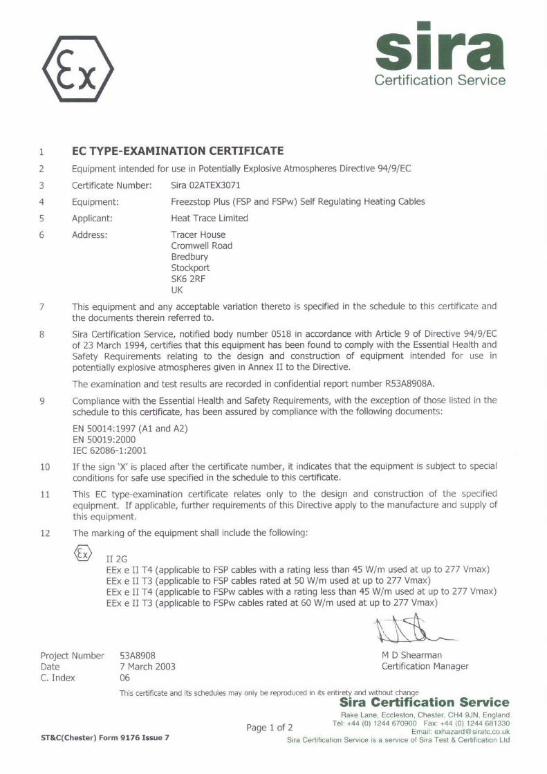
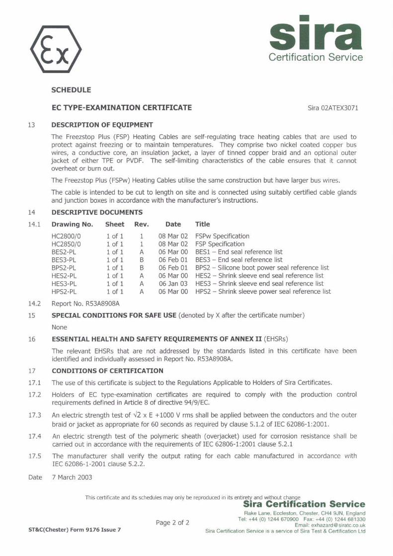
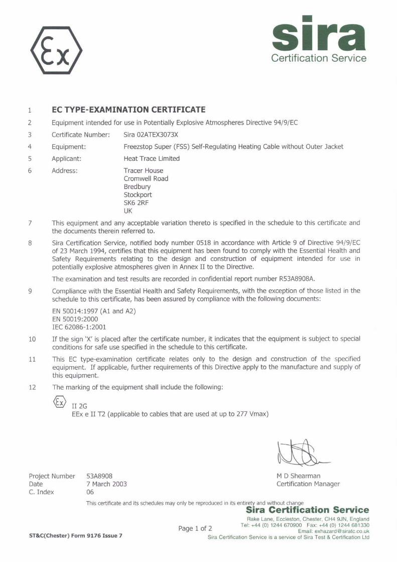
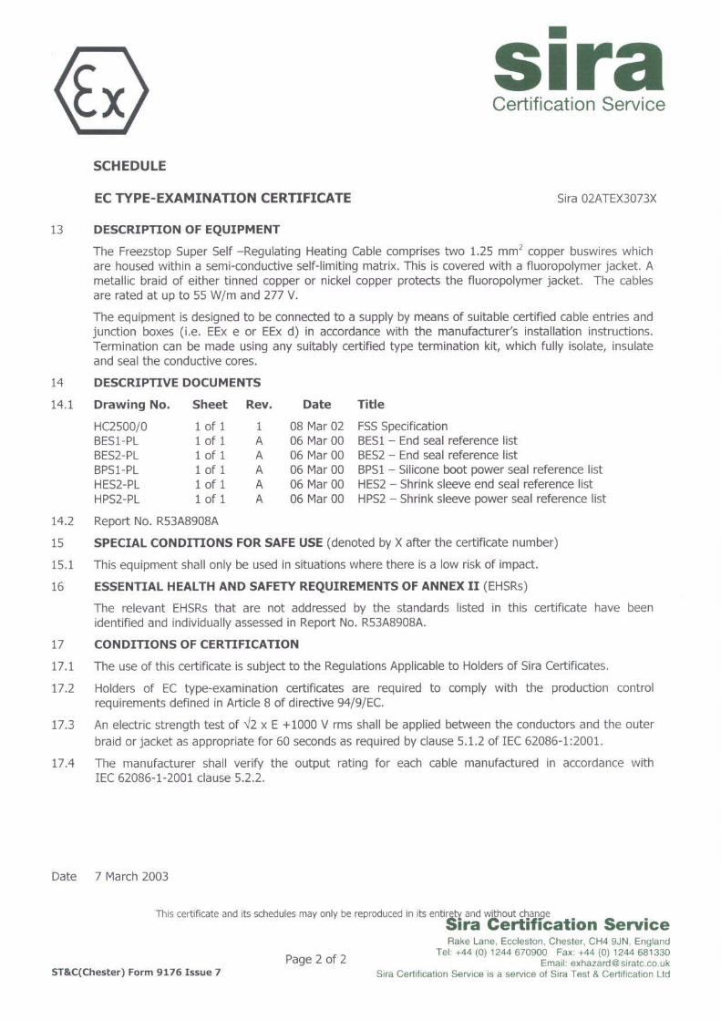

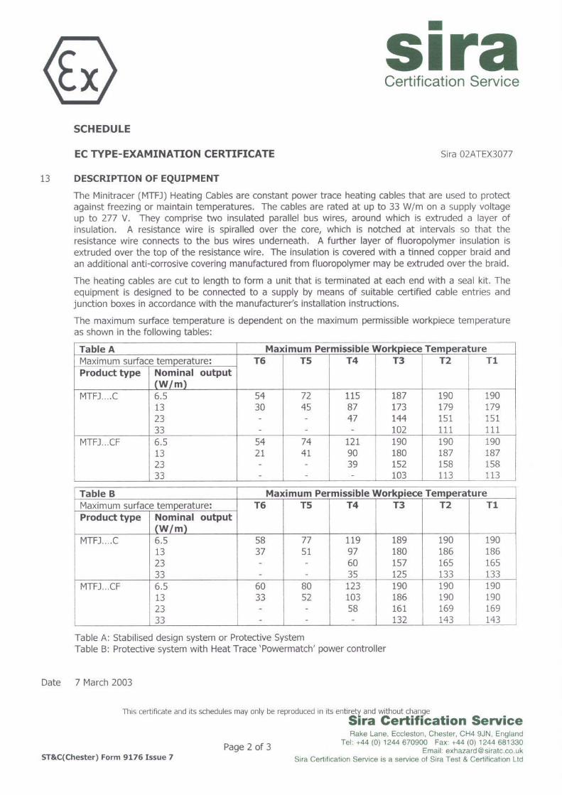
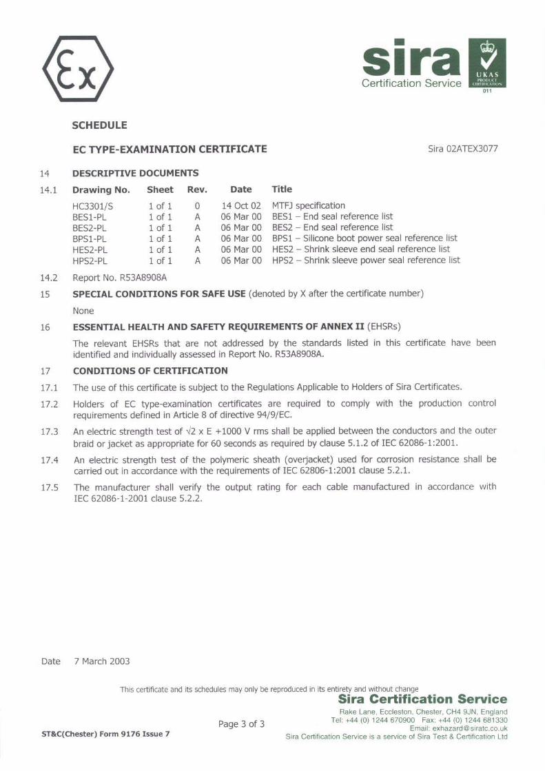

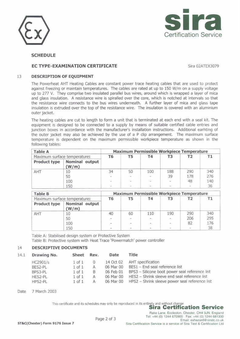
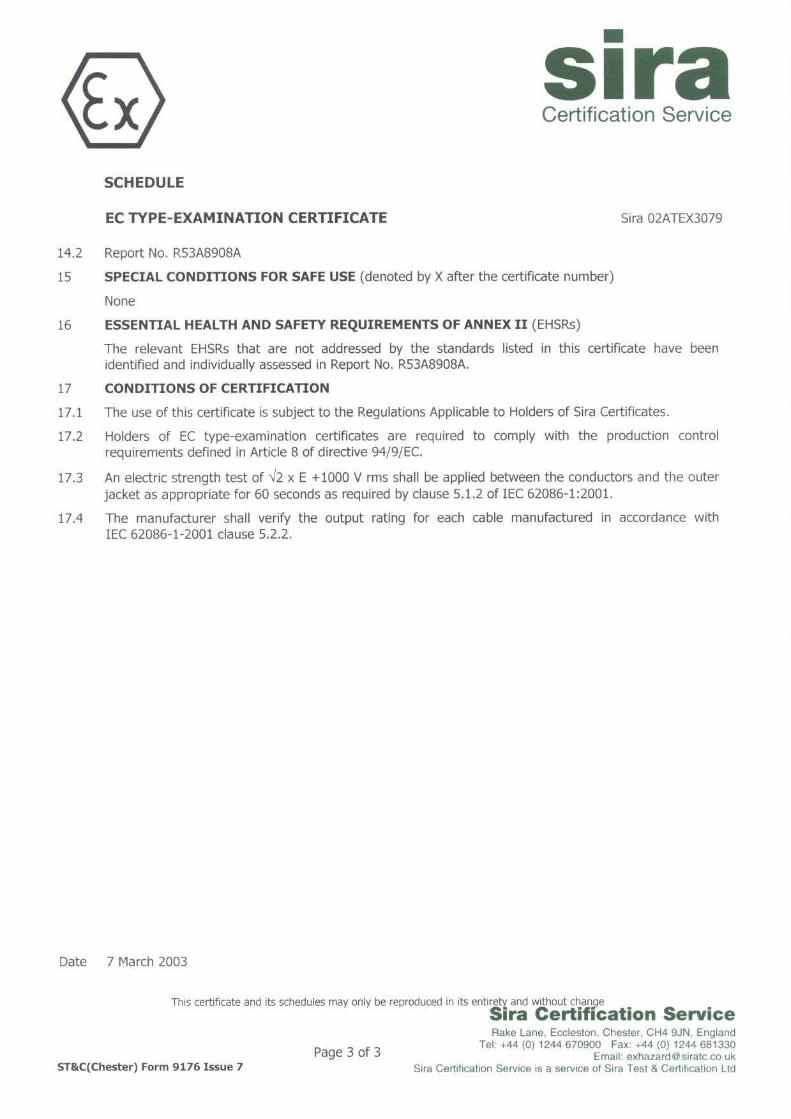
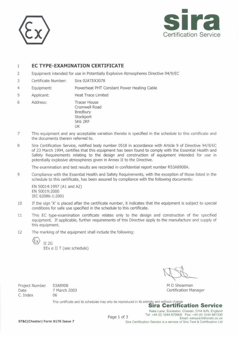
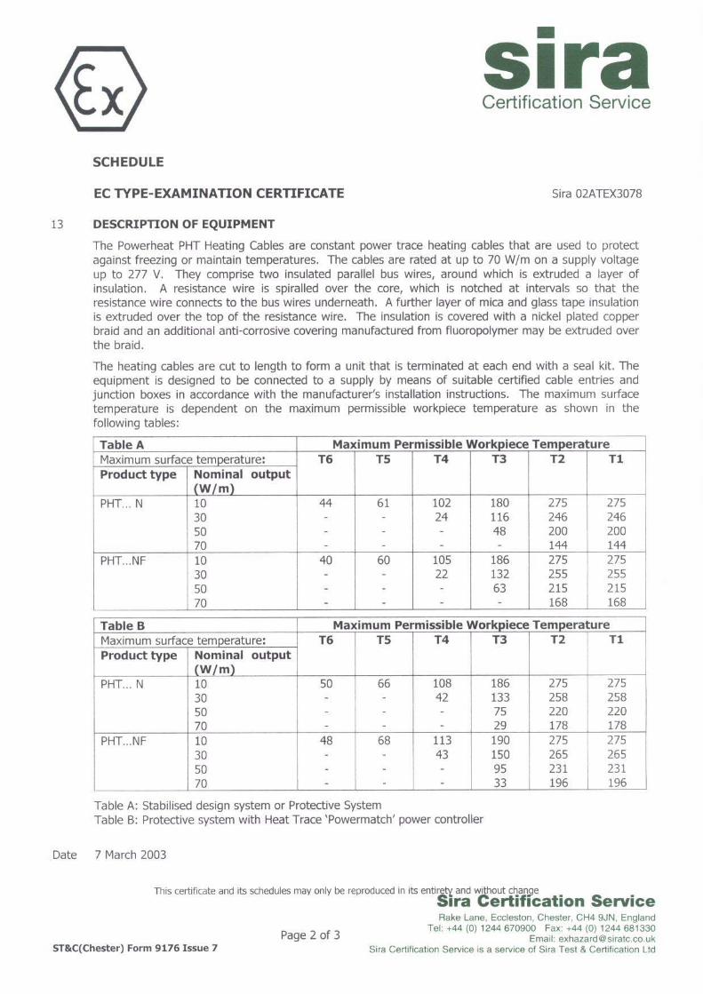
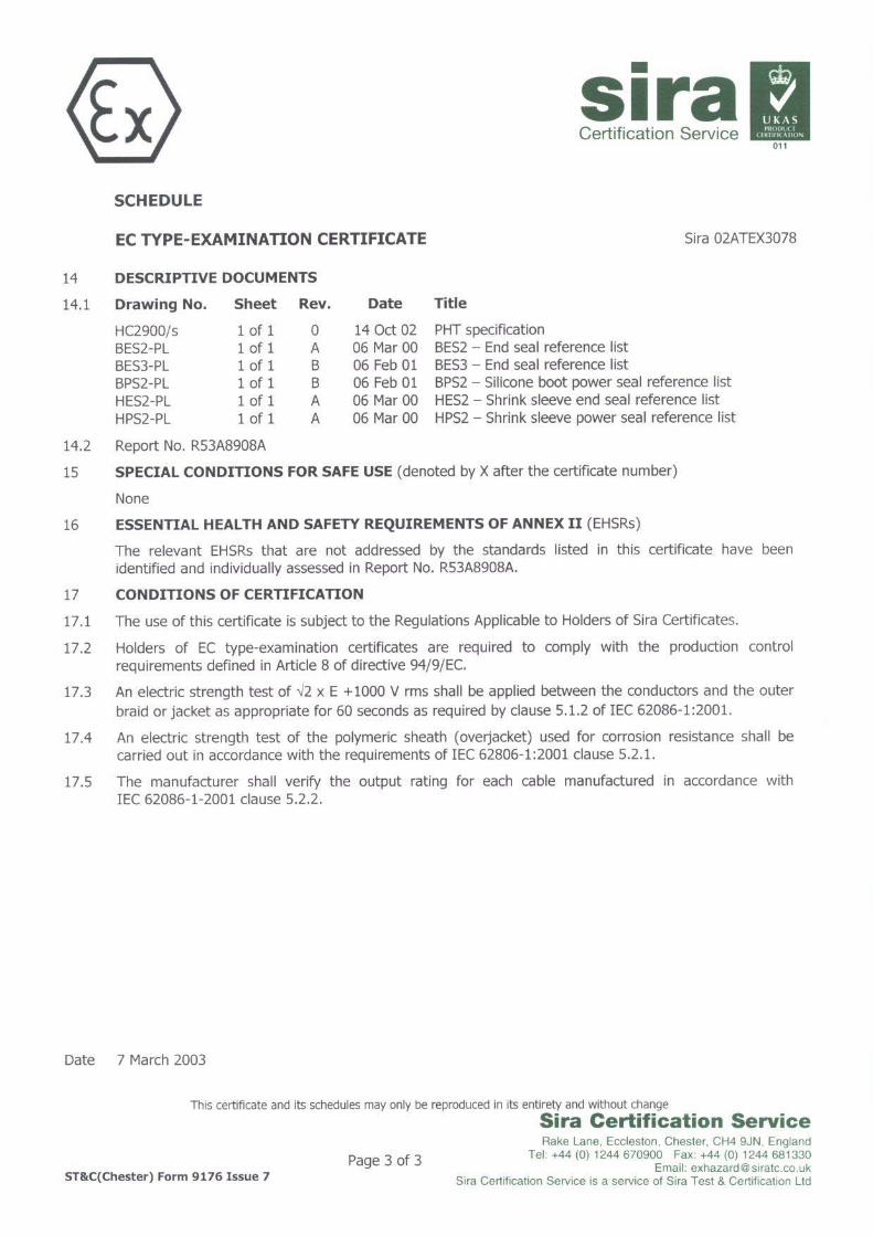
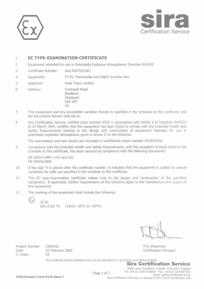
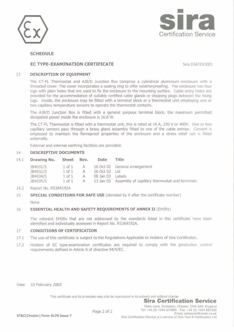
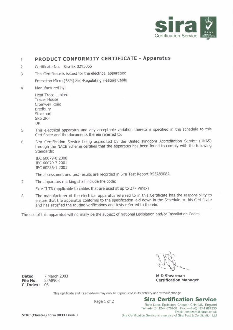
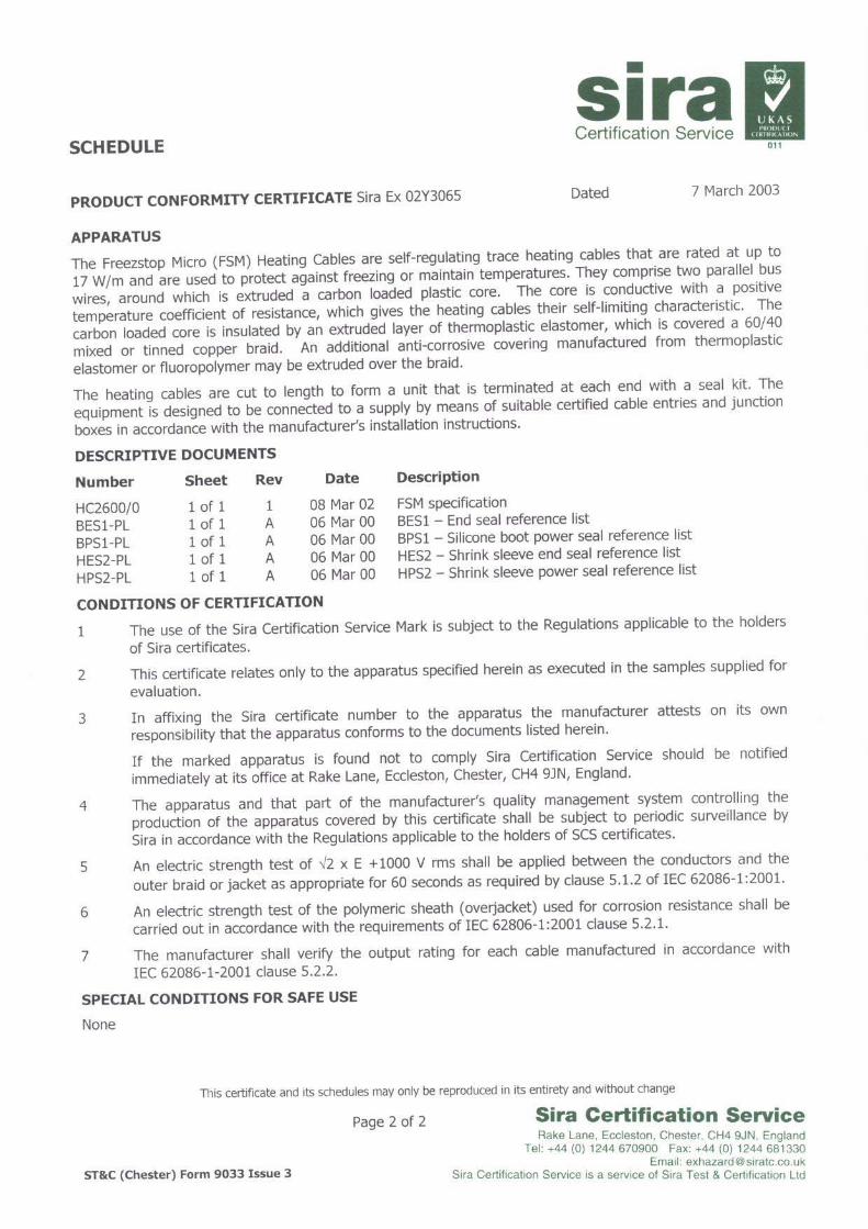
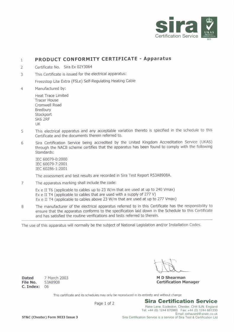
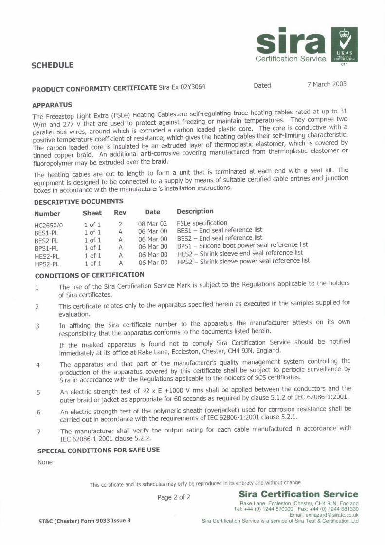
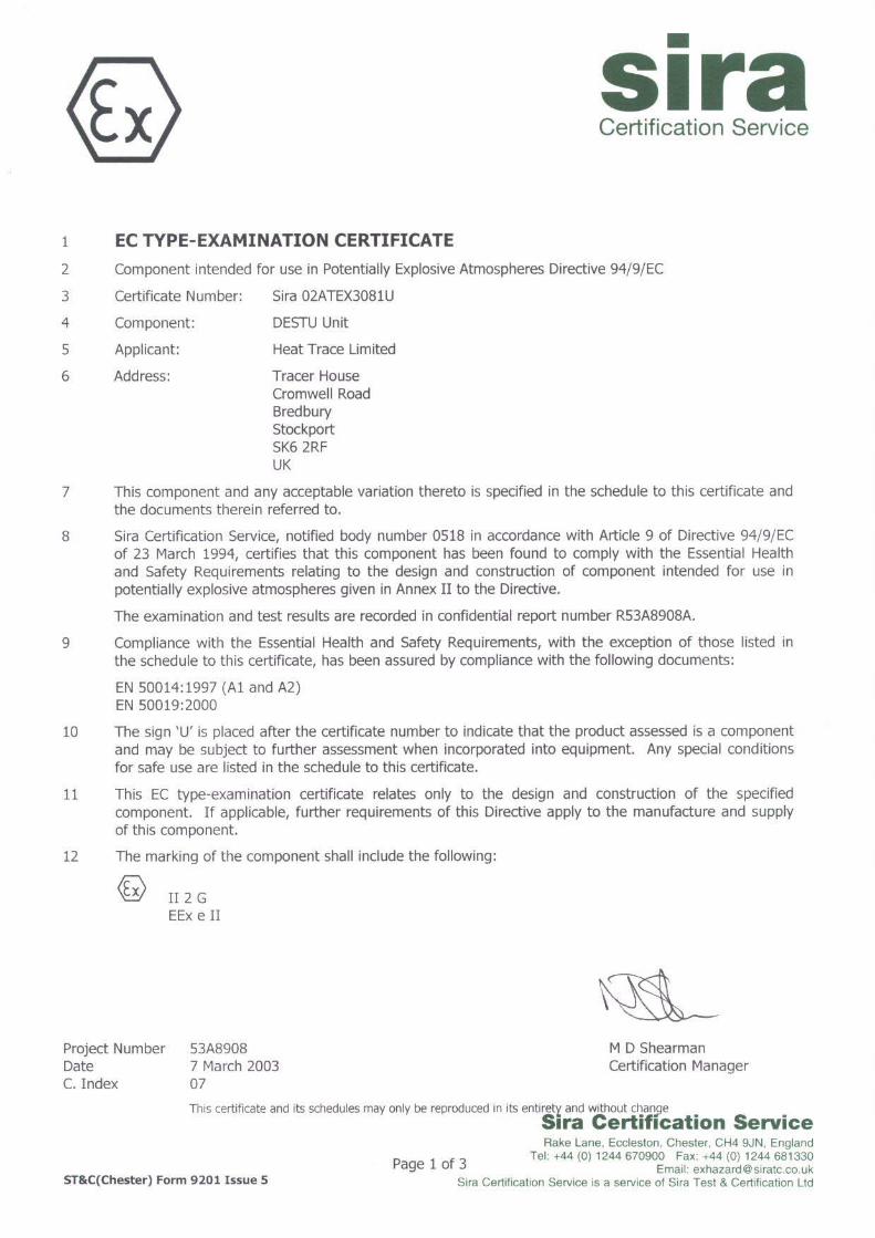
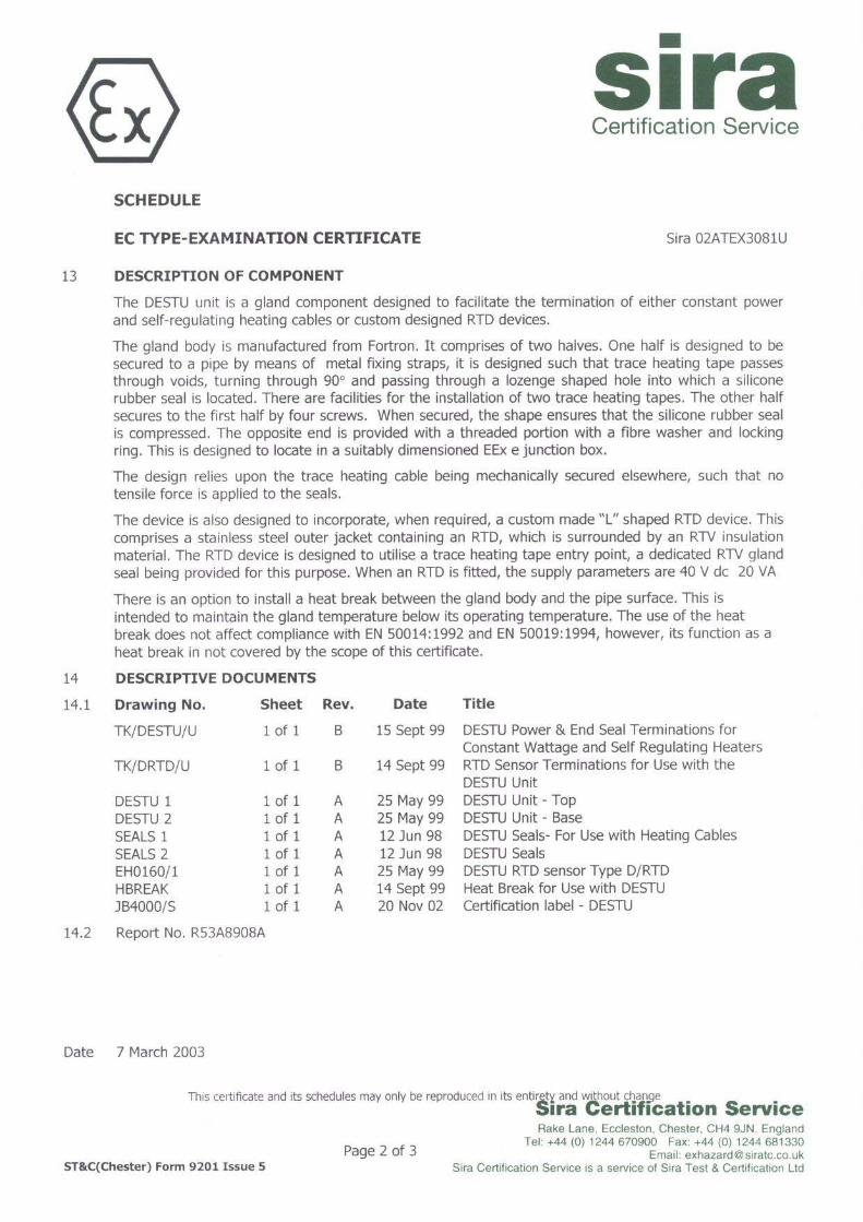
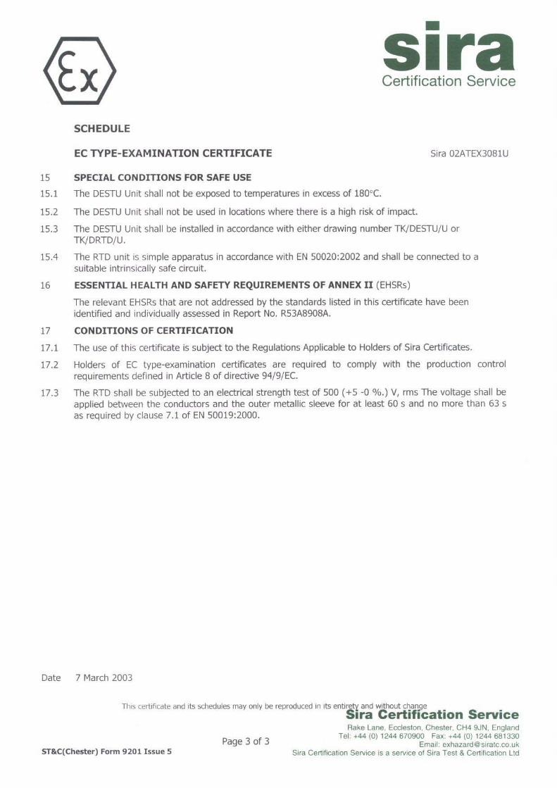
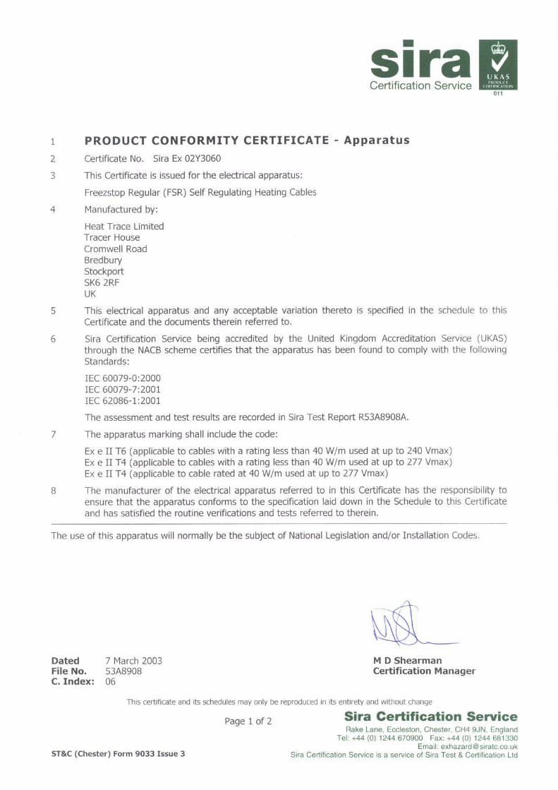
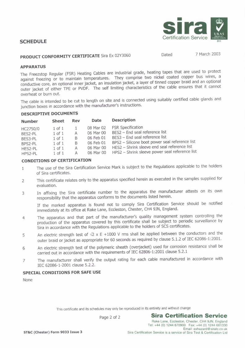
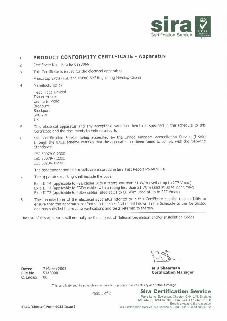
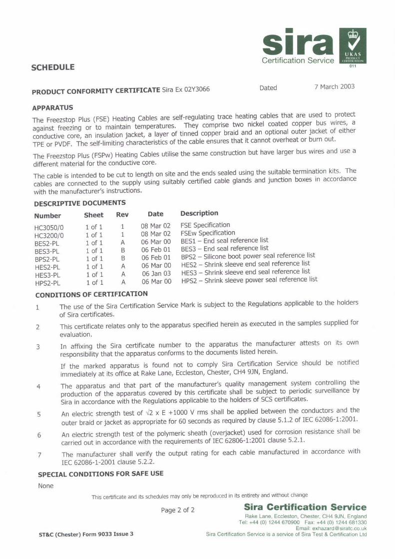
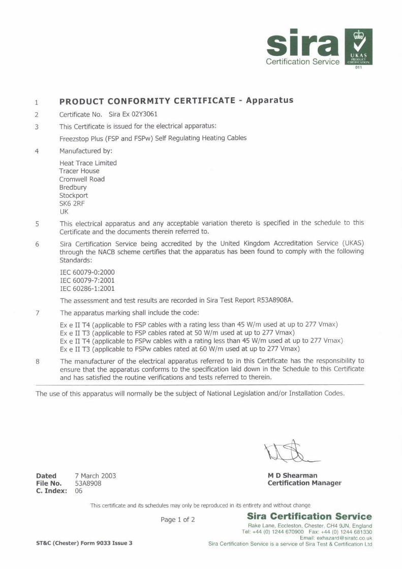
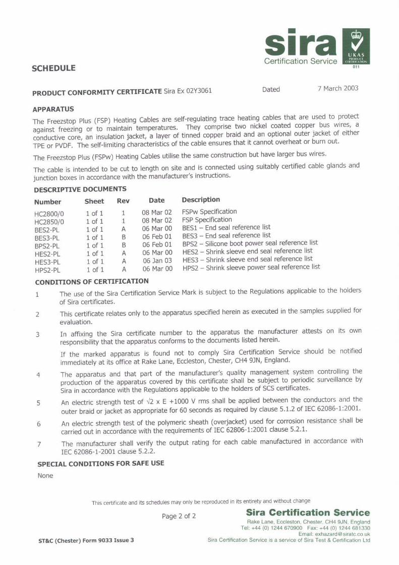
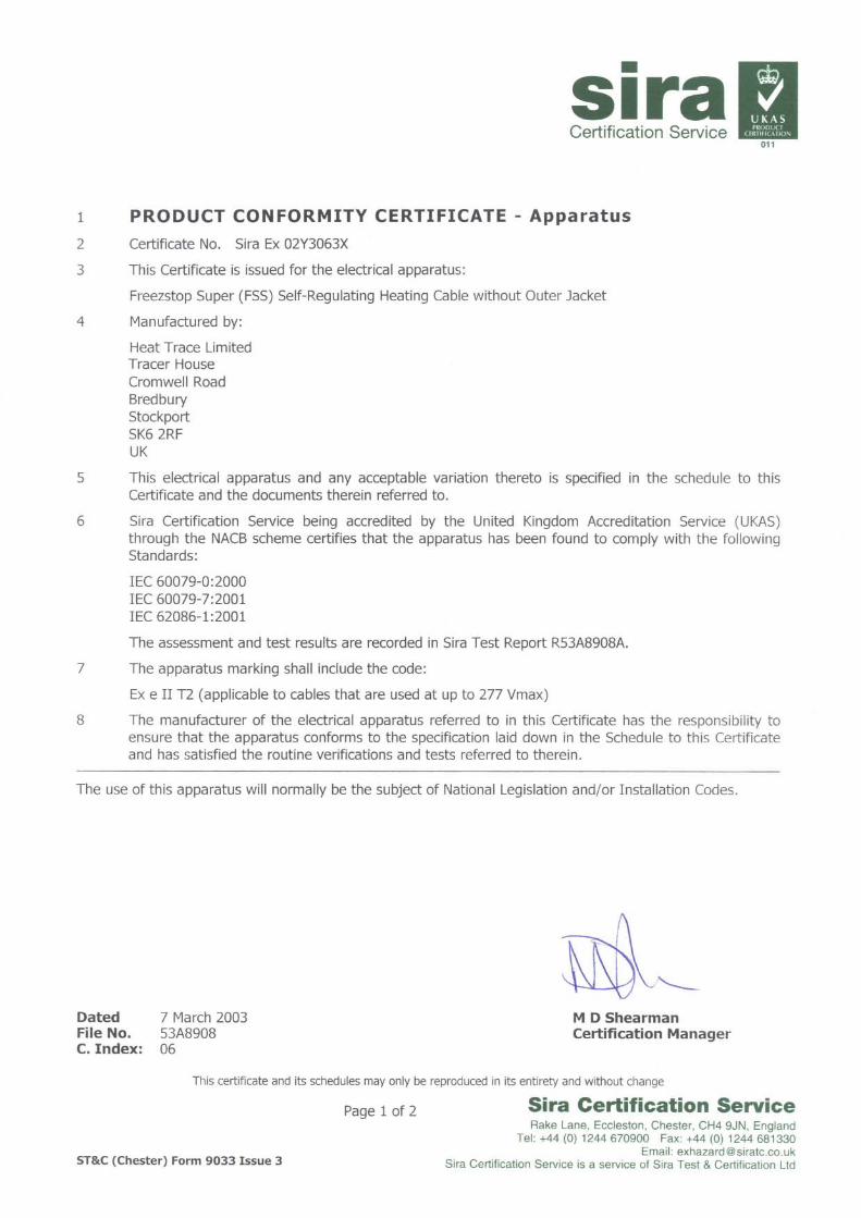
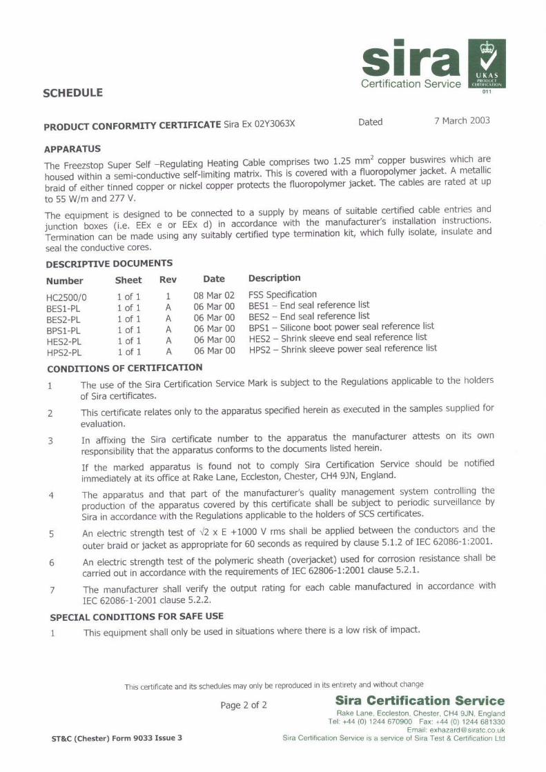
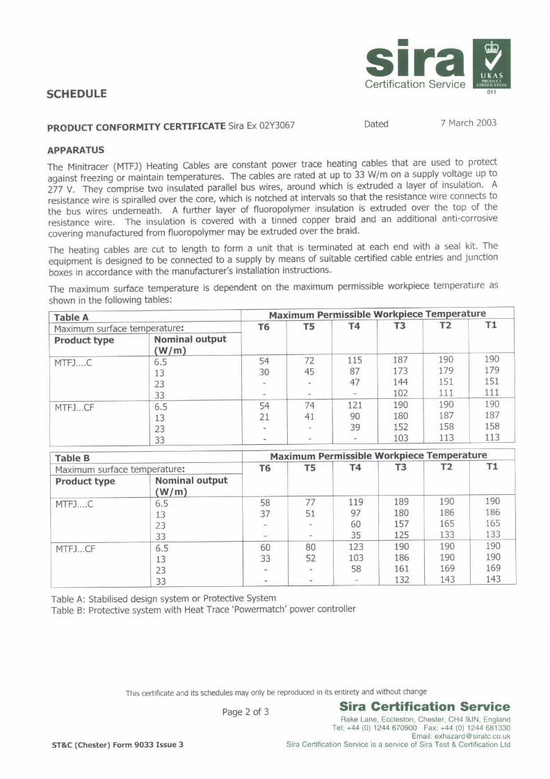
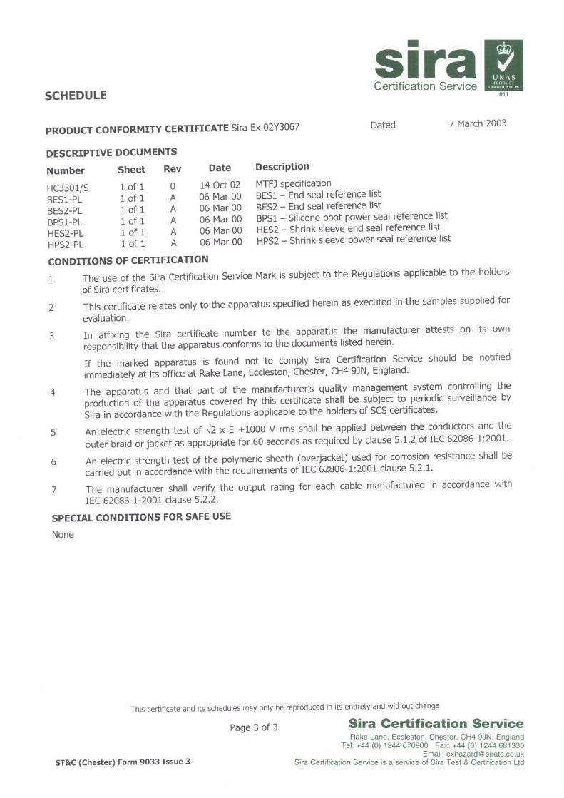
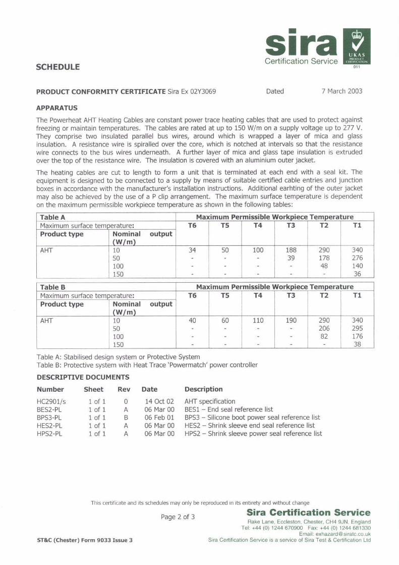
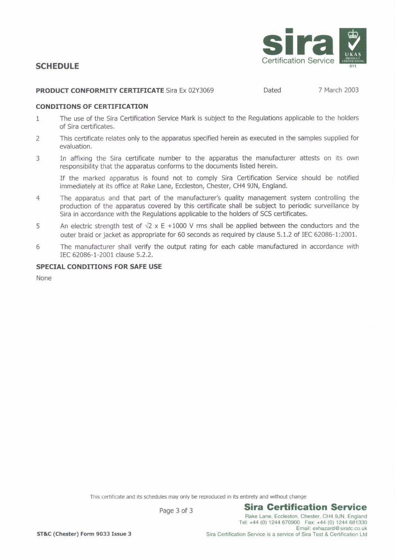
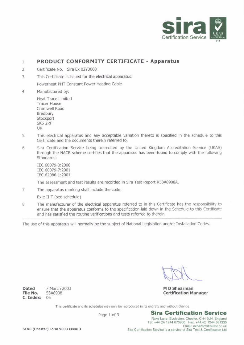
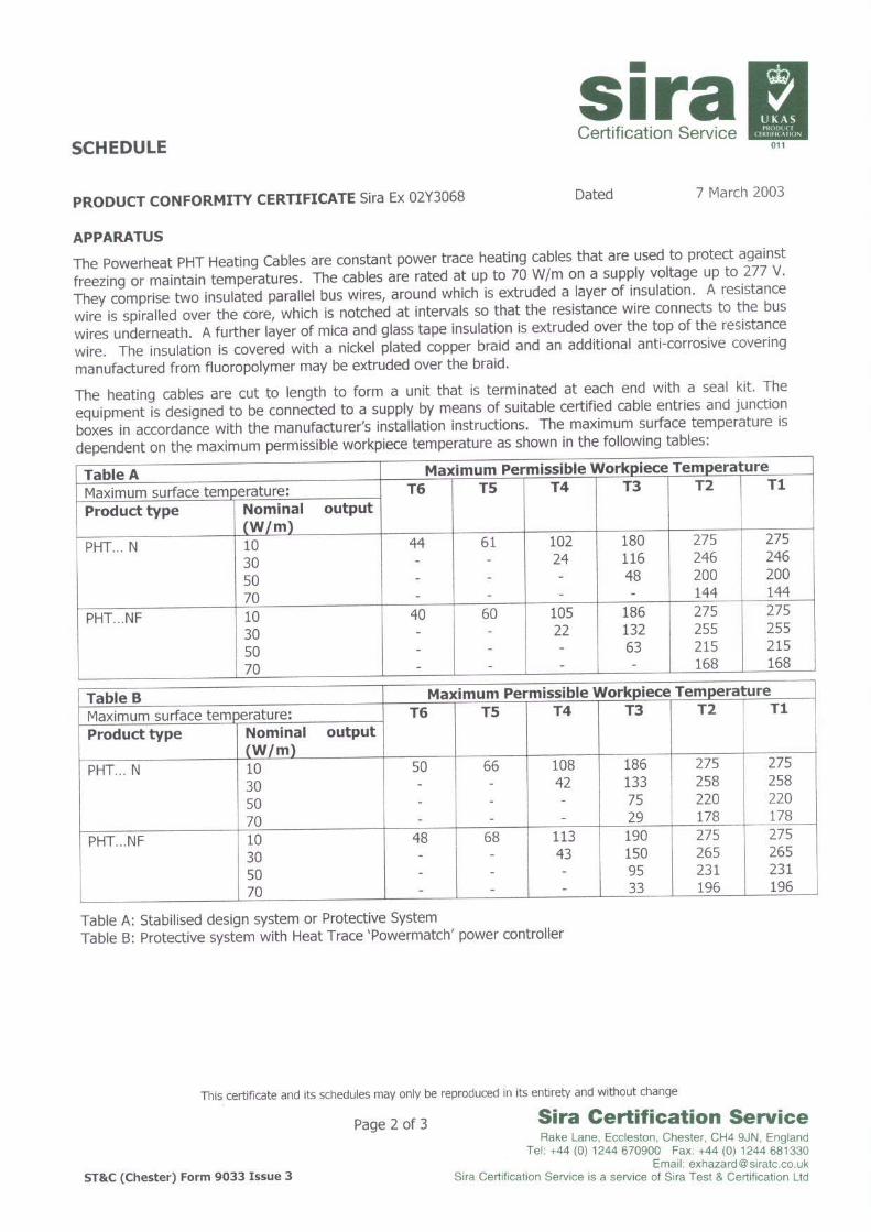
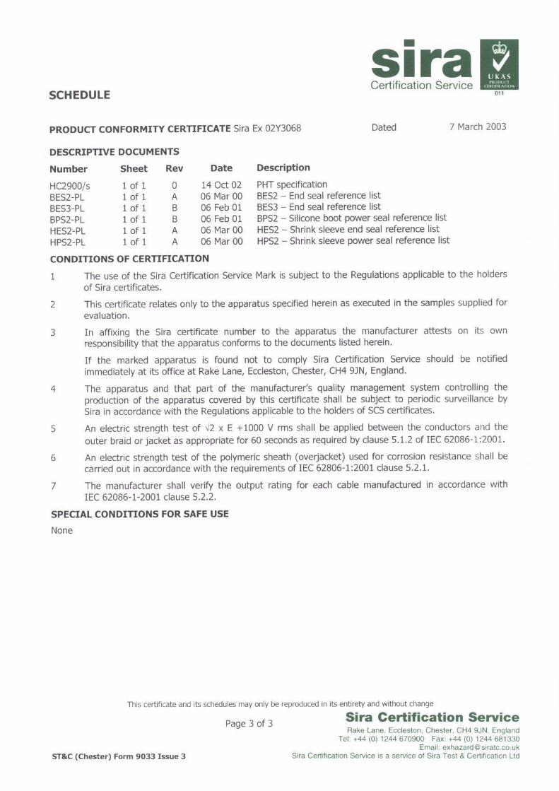
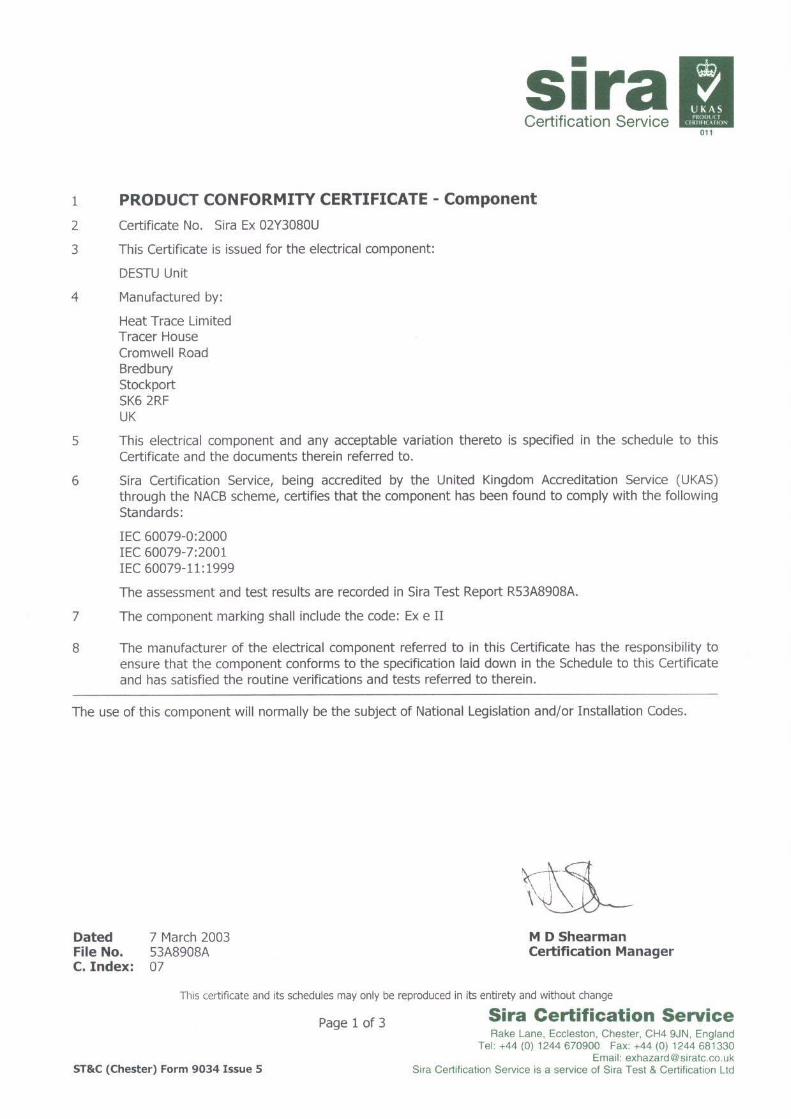
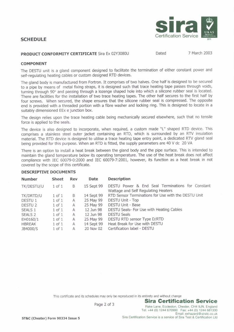
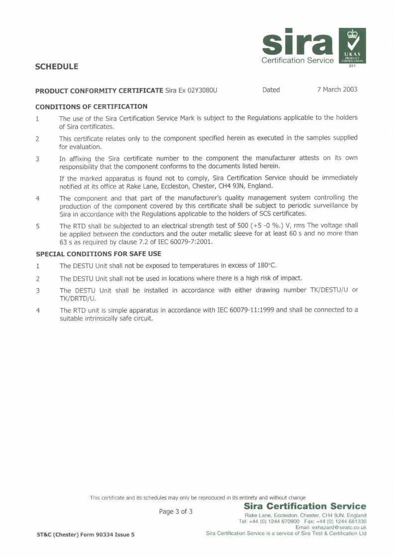
Recommended


