1
* "CompactFlash(TM)" is the registered trademark of SanDisk Corporation, U.S.A.
AMS-210EN / IP-420 INSTRUCTION MANUAL
i
CONTENTS
I. MECHANICAL SECTION (WITH REGARD TO THE SEWING MACHINE) 11. SPECIFICATIONS ....................................................................................................... 12. CONFIGURATION ....................................................................................................... 23. INSTALLATION ........................................................................................................... 3
3-1. Installing the electrical box ...........................................................................................................33-2. Installing and connecting the power switch ................................................................................33-3. Installation of the sewing machine head .....................................................................................53-4. Installing the drain receiver and the head support rubber ........................................................53-5. Safety switch ..................................................................................................................................63-6. Installing the throat plate auxiliary cover ....................................................................................63-7. Installing the panel.........................................................................................................................83-8. Attaching the pedal chain (For S specification only) .................................................................83-9. Installing the thread stand ............................................................................................................83-10. Raising the machine head ...........................................................................................................93-11. Connecting the cord ..................................................................................................................103-12. Installing the motor cover .........................................................................................................133-13. Managing the cord .....................................................................................................................133-14. Connecting the pneumatic components (Pneumatic type only) ...........................................143-15. Installing the air hose (Pneumatic type only) ..........................................................................173-16. Cautions for the compressed air supply (source of supply air) facility ...............................183-17. Installing the eye protection cover ...........................................................................................19
4. PREPARATION OF THE SEWING MACHINE .......................................................... 194-1. Lubrication....................................................................................................................................194-2. Attaching the needle ....................................................................................................................194-3. Needle size and gauge.................................................................................................................20
(1) Adjustment ................................................................................................................................20(2) Gauge .........................................................................................................................................20
4-4. Threading the machine head ......................................................................................................214-5. Installing and removing the bobbin case ..................................................................................214-6. Installing the bobbin ....................................................................................................................224-7. Adjusting the thread tension ......................................................................................................224-8. Intermediate presser height ........................................................................................................234-9. Adjusting the thread take-up spring ..........................................................................................23
5. OPERATION OF THE SEWING MACHINE ............................................................... 245-1. Sewing...........................................................................................................................................245-2. Needle thread clamp device ........................................................................................................25
II.OPERATION SECTION (WITH REGARD TO THE PANEL) ...............................................271. PREFACE .................................................................................................................. 272. WHEN USING IP-420 ................................................................................................ 31
2-1. Name of each section of IP-420 ..................................................................................................312-2. Buttons to be used in common ..................................................................................................322-3. Basic operation of IP-420 ............................................................................................................332-4. LCD display section at the time of sewing shape selection ....................................................35
(1) Sewing shape data input screen .............................................................................................35(2) Sewing screen ...........................................................................................................................37
ii
2-5. Performing sewing shape selection ...........................................................................................392-6. Changing item data ......................................................................................................................412-7. Checking pattern shape ..............................................................................................................432-8. Performing modification of needle entry point .........................................................................44
(1) Editing the thread tension .......................................................................................................44(2) Editing the intermediate presser height .................................................................................45
2-9. How to use temporary stop .........................................................................................................46(1) To continue performing sewing from some point in sewing ................................................46(2) To perform re-sewing from the start .......................................................................................47
2-10. When setting of sewing product is difficult because of interruption of needle tip ...................482-11. Winding bobbin thread ..............................................................................................................49
(1) When performing winding bobbin thread while performing sewing ...................................49(2) When performing winding bobbin thread only ......................................................................49
2-12. Using counter .............................................................................................................................50(1) Setting procedure of the counter ............................................................................................50(2) Count-up releasing procedure ................................................................................................52(3) How to change the counter value during sewing ..................................................................52
2-13. Performing new register of users’ pattern ...............................................................................532-14. Naming users’ pattern ...............................................................................................................542-15. Performing new register of pattern button ..............................................................................552-16. LCD display section at the time of pattern button selection .................................................56
(1) Pattern button data input screen ............................................................................................56(2) Sewing screen ...........................................................................................................................58
2-17. Performing pattern button No. selection .................................................................................60(1) Selection from the data input screen ......................................................................................60(2) Selection by means of the shortcut button ............................................................................61
2-18. Changing contents of pattern button .......................................................................................622-19. Copying pattern button .............................................................................................................632-20. Changing sewing mode .............................................................................................................642-21. LCD display section at the time of combination sewing ........................................................65
(1) Pattern input screen .................................................................................................................65(2) Sewing screen ...........................................................................................................................67
2-22. Performing combination sewing ..............................................................................................69(1) Selection of combination data .................................................................................................69(2) Creating procedure of the combination data .........................................................................70(3) Deleting procedure of the combination data .........................................................................71(4) Deleting procedure of the step of the combination data ......................................................71(5) Setting of the skip of steps ......................................................................................................72
2-23. Using the simple operation mode ............................................................................................722-24. LCD display when the simple operation is selected...............................................................73
(1) Data input screen (individual sewing) ....................................................................................73(2) Sewing screen (individual sewing) .........................................................................................76(3) Data input screen (combination sewing) ................................................................................79(4) Sewing screen (combination sewing) .....................................................................................81
2-25. Changing memory switch data .................................................................................................832-26. Using information ......................................................................................................................84
(1) Observing the maintenance and inspection information .....................................................84(2) Releasing procedure of the warning .......................................................................................85
2-27. Using communication function ................................................................................................86(1) Handling possible data ............................................................................................................86

iii
(2) Performing communication by using the media ...................................................................86(3) Performing communication by using USB .............................................................................86(4) Take-in of the data ....................................................................................................................87(5) Taking in plural data together ..................................................................................................88
2-28. Performing formatting of the media .........................................................................................902-29. USING 2-STEP STROKE FUNCTION .........................................................................................91
(1) Setting of 2-step stroke function .............................................................................................91(2) Setting of 2-step stroke position .............................................................................................91(3) Motion of 2-step stroke function .............................................................................................93
2-30. Operation at the time of X/Y motor position slip .....................................................................95(1) When the error is displayed during sewing ...........................................................................95(2) When the error is displayed after end of sewing ...................................................................96(3) When the rest switch is not displayed ....................................................................................96
3. MEMORY SWITCH DATA LIST ................................................................................. 973-1. Data list .........................................................................................................................................973-2. Initial value list ...........................................................................................................................103
4. ERROR CODE LIST ................................................................................................ 1055. MESSAGE LIST ...................................................................................................... 112
III. MAINTENANCE OF SAWING MACHINE ...............................................1151. MAINTENANCE ....................................................................................................... 115
1-1. Adjusting the height of the needle bar (Changing the length of the needle) ....................... 1151-2. Adjusting the needle-to-shuttle relation .................................................................................. 1151-3. Height and angle of the work clamp......................................................................................... 117
(1) Height of the work clamp (S type) ......................................................................................... 117(2) Height of the work clamp (L type) ......................................................................................... 118(3) Angle of the work clamp (all models excluding 1306L type) .............................................. 118
1-4. Adjusting the vertical stroke of the intermediate presser ...................................................... 1191-5. The moving knife and counter knife......................................................................................... 1191-6. Needle thread clamp device ......................................................................................................1201-7. Thread breakage detector plate ...............................................................................................1201-8. Draining waste oil ......................................................................................................................1201-9. Amount of oil supplied to the hook ..........................................................................................1211-10. Replacing the fuse ...................................................................................................................1211-11. Changing the voltage of 100 ⇔ 200V......................................................................................1221-12. Replenishing the designated places with grease .................................................................123
(1) Location where exclusive grease is provided .....................................................................124(2) Points to be applied with JUKI Grease A ..............................................................................124(3) Points to be applied with JUKI Grease B .............................................................................126(4) Applying grease to other sections ........................................................................................127
1-13. Troubles and corrective measures (Sewing conditions)......................................................1282. OPTIONAL ............................................................................................................... 130
2-1. Table of Needle hole guide ........................................................................................................1302-2. Silicon oil tank ...........................................................................................................................1302-3. Bar code reader ..........................................................................................................................131

– 1 –
1. SPECIFICATIONS
I. MECHANICAL SECTION (WITH REGARD TO THE SEWING MACHINE)
1 Sewing area X (lateral) direction Y (longitudinal) direction AMS-210EN-1306 : 130 mm × 60 mmAMS-210EN-1510 : 150 mm × 100 mmAMS-210EN-2210 : 220 mm × 100 mm
2 Max. sewing speed 2,800 sti/min (When sewing pitch is 4 mm or less)3 Stitch length 0.1 to 12.7 mm (Min. resolution : 0.05 mm)4 Feed motion of feeding
frameIntermittent feed (2-shaft drive by stepping motor)
5 Needle bar stroke 41.2 mm6 Needle GROZ-BECKERT 134, 135 × 17, ORGAN needle DP × 5, DP × 177 Lift of feeding frame Max. 25mm (Pneumatic type only Max.30mm)8 Intermediate presser stroke 4 mm (Standard) (0 to 10 mm)9 Lift of intermediate presser 20 mm
10 Intermediate presser DOWN position variable
Standard 0 to 3.5 mm (Max. 0 to 7.0 mm)
11 Shuttle Double-capacity semi-rotary hook12 Lubricating oil New Defrix Oil No. 2 (Supplied by oiler)13 Memory of pattern data Main body, Media
• Main body : Max. 999 patterns (Max. 50,000 stitches/pattern)• Media : Max. 999 patterns (Max. 50,000 stitches/pattern)
14 Temporary stop facility Used to stop machine operation during a stitching cycle.15 Enlarging / Reducing
facilityAllows a pattern to be enlarged or reduced on the X axis and Y axis independently when sewing a pattern. Scale : 1% to 400% times (0.1% steps)
16 Enlarging / Reducing method
Pattern enlargement / reduction can be done by increasing / decreasing either stitch length or the number of stitches. (Increasing/decreasing stitch length only can be performed when pattern button is selected.)
17 Max. sewing speed lim-itation
200 to 2,800 sti/min (Scale : 100 sti/min steps)
18 Pattern selection facility Pattern No. selection method(Main body : 1 to 999, Media : 1 to 999)
19 Bobbin thread counter UP/DOWN method (0 to 9,999)20 Sewing counter UP/DOWN method (0 to 9,999) 21 Memory back-up In case of a power interruption, the pattern being used will automatically be stored in
memory.22 2nd origin setting facility Using jog keys, a 2nd origin (needle position after a sewing cycle) can be set in the
desired position within the sewing area. The set 2nd origin is also stored in memory.23 Sewing machine motor Servo-motor24 Dimensions 1,200mm (W) × 710mm (L) × 1,200mm (H) (Excluding thread stand)25 Mass (gross mass) Machine head 69kg, control box 16.5kg 26 Power consumption 450 VA 27 Operating temperature
range5˚C to 35˚C
28 Operating humidity range 35 % to 85 % (No dew condensation)29 Line voltage Rated voltage ±10% 50 / 60 Hz30 Air pressure used Standard 0.35 to 0.4 MPa (Max. 0.55 MPa)(Pneumatic type only)31 Air consumption 1.8 dm3 / min (ANR) (Pneumatic type only)32 Needle highest position
stop facilityAfter the completion of sewing, the needle can be brought up to its highest position.
33 Noise - Equivalent continuous emission sound pressure level (LpA) at the workstation : A-weighted value of 82 dB; (Includes KpA = 2.5 dB); according to ISO 10821- C.6.2 -ISO 11204 GR2 at 2,800 sti/min *1.- Sound power level (LWA) ;A-weighted value of 91 dB; (Includes KWA = 2.5 dB); according to ISO 10821- C.6.2 -ISO 3744 GR2 at 2,800 sti/min *1.Time required for sewing: 2.2 sec, using Pattern No. 102
*1 "sti/min" is an abbreviation for "stitches per minute."

– 2 –
Air regulator (for pneumatic type only)
2. CONFIGURATION
❶ Machine head❷ Wiper switch❸ Temporary stop switch❹ Feeding frame❺ Intermediate presser❻ Thread stand❼ Operation panel (IP-420)❽ Power switch
(also used as the emergency stop switch)❾ Control box� Foot pedal� Manual pedal (Excluding pneumatic type)
❶
❷
❸
❹
❻❼
❽
❾
�
❺
�

– 3 –
3. INSTALLATION
3-1. Installing the electrical box
Install the electrical box on the underside of the table at the location illustrated using round-head bolt ❶, plain washer ❷, spring washer ❸ and nut ❹ supplied with the machine, and using bolt hav-ing hexagonal indentation on the head ❺ spring washer ❻ and plain washer ❼ supplied with the machine.
1) Installing the power switch Fix power switch ❶ under the machine table
with wood screws ❷ . Fix the cable with staples ❸ supplied with the
machine as accessories in accordance with the forms of use.
Five staples ❸ including the staple for fixing the operation panel cable are supplied as accessories.
3-2. Installing and connecting the power switch
❶
❷
❸
❶❺
❻❼
❷❸❹

– 4 –
(2) Connecting the power source cord The factory default voltage type is indicated on the voltage indication plate. Connect the cord in ac-
cordance with the specifications.
Voltage indication seal (3-phase type only)
Voltage caution seal
Rating label
Brown
Brown
Light blue
Light blue
Light blueGreen/Yellow– GND
Green/Yellow
Plug
Power source cord
Power switch
AC200 V, AC220 VAC230 V, AC240 V
• Connecting single phase 200V, 220V, 230V and 240V
White
AC200 V, AC220 V, AC240 V
• Connecting three phase 200V, 220V and 240V
Red WhiteBlack
1. Never use under the wrong volt-age and phase.
2. When changing the voltage, refer to the item of "III-1-11. Changing the voltage of 100 ⇔ 200V" p.122
Table
Control box
Black
Red
Green/Yellow
Brown
Green/Yellow– GND
Red
Green
PlugControl box
Green/Yellow
Black
White
Power switch
Table
Electric shock warning label

– 5 –
1) Fit the holes of hinges A to the holes of table and fix as shown in the figure.
3-3. Installation of the sewing machine head
In case of the pneumatic type, fix sole-noid valve installing plate ❶ as well.
WARNING : To prevent possible accidents caused by the full of the sewing machine, perform the work by two
persons or more when the machine is moved.
A ❶
3-4. Installing the drain receiver and the head support rubber
1) Fix drain receiver ❷ in the installing hole of table ❶ with two setscrews ❸ .
2) Screw in drain bin ❹ to drain receiver ❷ .3) Insert sewing machine drain pipe ❺ into drain
bin ❹ .4) Insert head support rubbers ❻ to machine bed ❼ . 5) Bundle the cables with clip bands ❽ as shown
in the figure. (Excluding air tube)
1. Insert drain pipe ❺ until it will go no further so that it does not come off drain bin ❹ when tilting the ma-chine head.
2. Remove the tape fixing drain pipe ❺ .
❶
❷
❹
❻
❻
❻
❻
❸❻
❺
❼
❻
❽
– 6 –
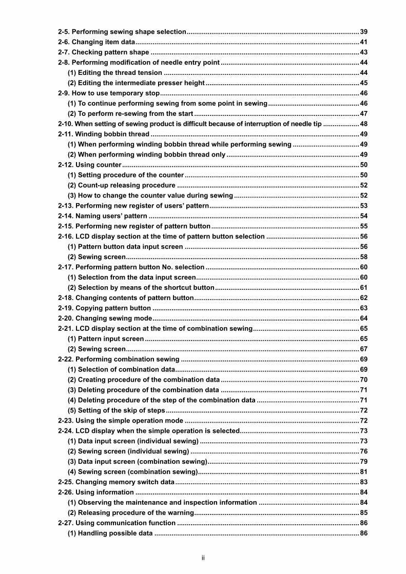
3-6. Installing the throat plate auxiliary cover
[When using area 1306]1) Temporarily fix throat plate auxiliary
cover supports A ❷ and B ❸ to the machine bed with setscrews (M5) ❻ .
2) Move the cloth feed base to the rear, and place throat plate auxiliary cover ❶ from between lower plate ❼ and throat plate ❽ . At this time, be careful not to bend lower plate ❼ .
3) Fix throat plate auxiliary cover ❶ with throat plate auxiliary cover setscrews ❺ and washers ❹ .
❶
❹ ❸
❺
❻
❷
❹
❽❼
[Area 1306]
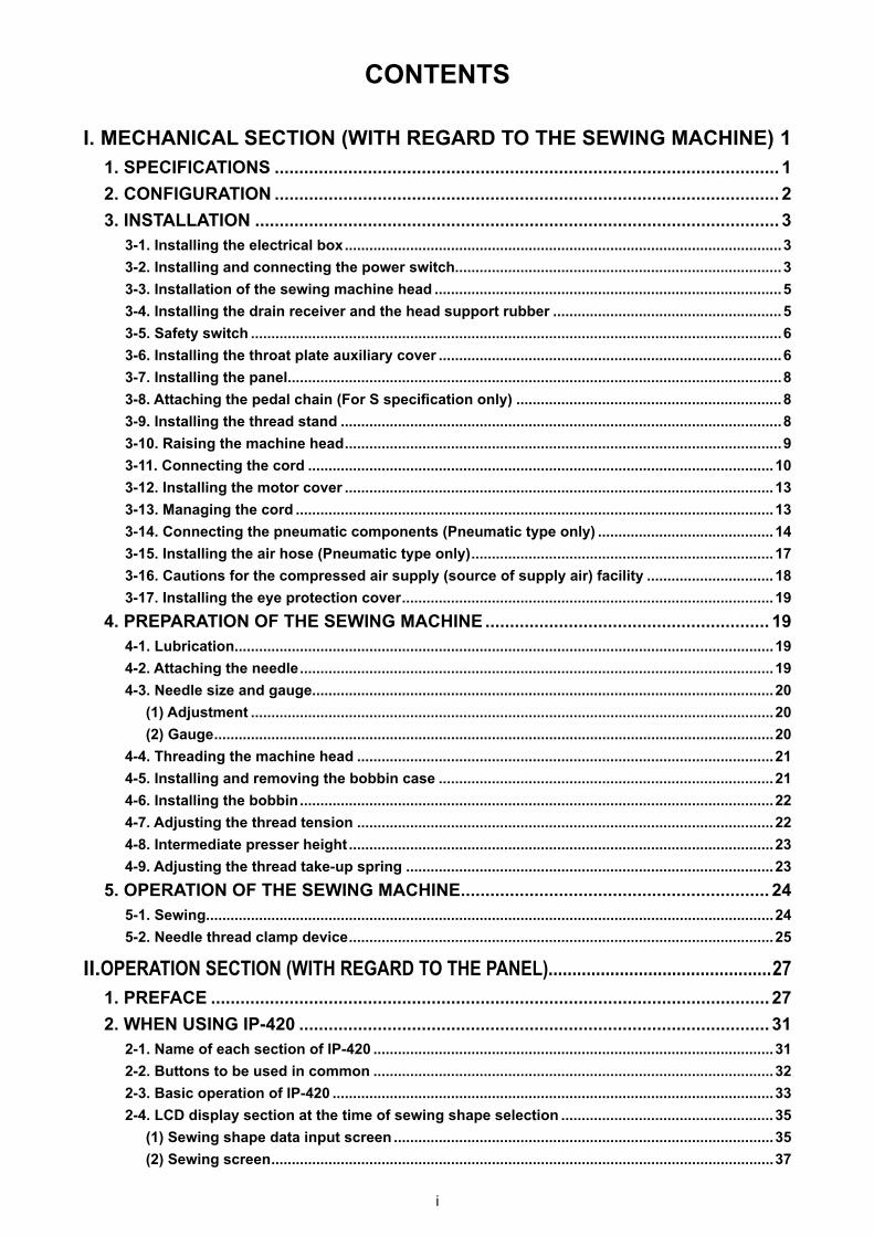
3-5. Safety switch
❶
Remove tape ❷ fixing the lever section of safety switch ❶.
1. When using the safety switch without removing tape ❶ , it is very dangerous since the sewing ma-chine works even in the state that it is tilted.
2. In case error 302 occurs when the sewing machine works after setup, loosen the safety switch ❷ fitting screw with a screwdriver, and lower � the switch to the downside of the sewing machine.
❷
WARNING : Be careful not to bump your head or any other parts of your body against the throat plate auxiliary
cover when you bend over your work.

– 7 –
Left-hand and right-hand shapes of throat plate auxiliary cover support � are different. So, be careful.
❶
❶
❽
Within 0.3 mm ❶
2���
�
❺�
[Areas 1510 and 2210]
[When area 1510 or 2210 is used]1) Temporarily fix throat plate auxiliary
cover supports A ❷ and B ❸ to the machine bed with setscrews (M5) ❻ .
For the screw ❻ which tightens the throat plate auxiliary cover support A ❷ , select the screw which is easier to use between the hexagon socket and the screw with plus and minus slots.
2) Move the cloth feed base to the rear, and place throat plate auxiliary cover ❶ from between lower plate ❼ and throat plate ❽ . At this time, be careful not to bend lower plate ❼ .
3) Fix throat plate auxiliary cover ❶ with throat plate auxiliary cover setscrews ❺ and nuts (small) ❹ .
4) Temporarily fix throat plate auxiliary cover support � to the machine bed with setscrews (M6) � .
5) Temporarily fix throat plate auxiliary cover base � to throat plate auxiliary cover support � with setscrews � and nuts (large) � .
6) Fix throat plate auxiliary cover ❶ with throat plate auxiliary cover setscrews ❺ and nuts (large) � .
❶
❹ ❸
❺
❻
❷
❹
❽❼
1. Be careful so as not to mis-take the direction of throat plate auxiliary cover support.
2. Fix the throat plate auxiliary cover ❶ so that is higher than the throat plate ❽ (within 0.3 mm). When it is lower than the throat plate ❽ , needle breakage or the like due to the defective feed will be caused.
3. Confirm by putting a ruler or the like that the throat plate auxiliary cover ❶ is horizon-tally installed. If not, throat plate auxiliary cover ❶ and lower plate ❼ come in contact partially with each other, and abnormal worn-out will be caused.
[Areas 1510 and 2210]
– 8 –
❶❷
❸
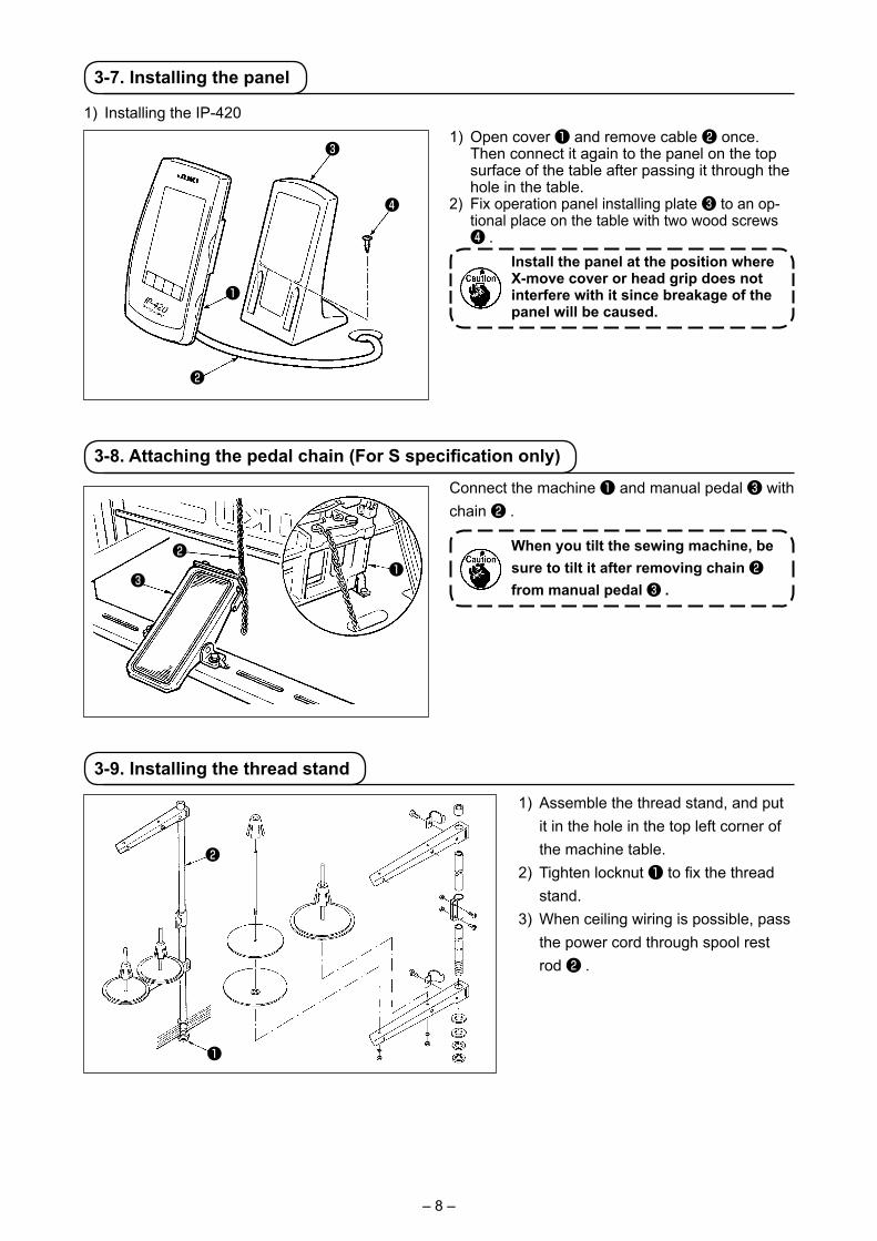
3-8. Attaching the pedal chain (For S specification only)
❶
❷
3-9. Installing the thread stand
1) Assemble the thread stand, and put it in the hole in the top left corner of the machine table.
2) Tighten locknut ❶ to fix the thread stand.
3) When ceiling wiring is possible, pass the power cord through spool rest rod ❷ .
Connect the machine ❶ and manual pedal ❸ with chain ❷ .
When you tilt the sewing machine, be sure to tilt it after removing chain ❷ from manual pedal ❸ .
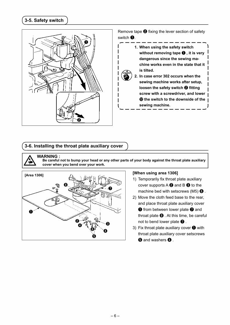
3-7. Installing the panel
1) Installing the IP-420
❹
❸
❶
❷
1) Open cover ❶ and remove cable ❷ once. Then connect it again to the panel on the top surface of the table after passing it through the hole in the table.
2) Fix operation panel installing plate ❸ to an op-tional place on the table with two wood screws ❹ .
Install the panel at the position where X-move cover or head grip does not interfere with it since breakage of the panel will be caused.
– 9 –
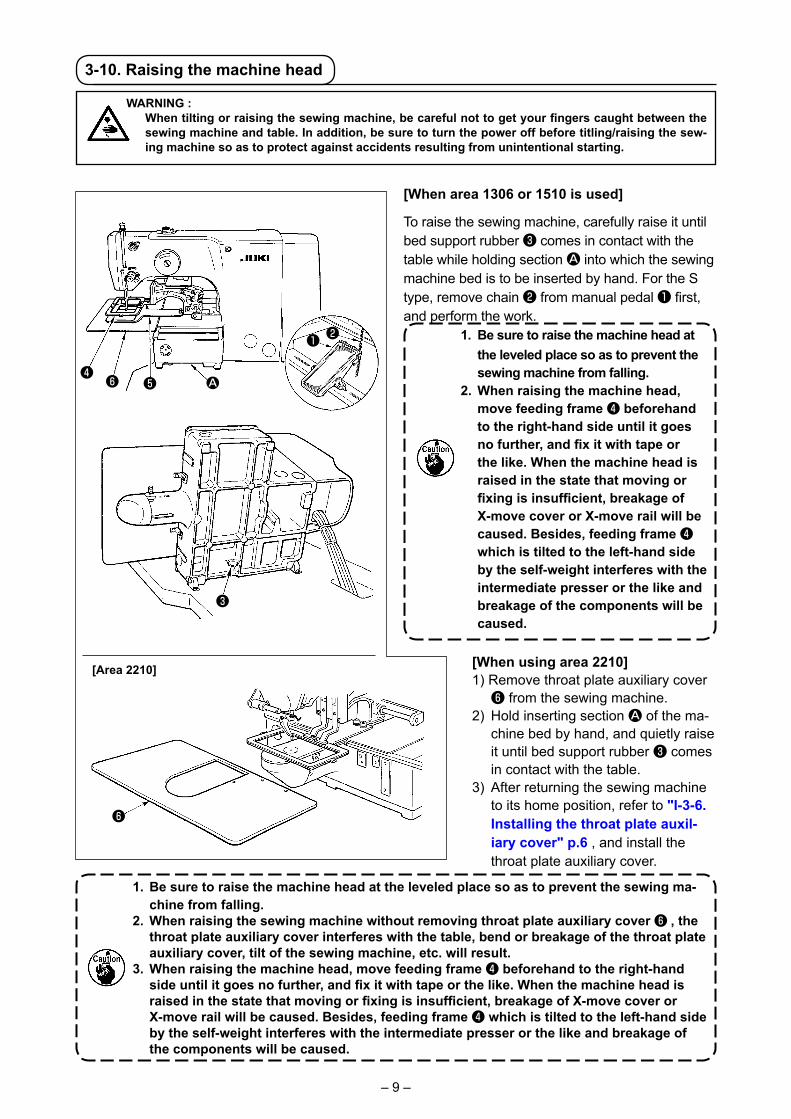
3-10. Raising the machine head
WARNING : When tilting or raising the sewing machine, be careful not to get your fingers caught between the
sewing machine and table. In addition, be sure to turn the power off before titling/raising the sew-ing machine so as to protect against accidents resulting from unintentional starting.
[When area 1306 or 1510 is used]
To raise the sewing machine, carefully raise it until bed support rubber ❸ comes in contact with the table while holding section A into which the sewing machine bed is to be inserted by hand. For the S type, remove chain ❷ from manual pedal ❶ first, and perform the work. 1. Be sure to raise the machine head at
the leveled place so as to prevent the sewing machine from falling.
2. When raising the machine head, move feeding frame ❹ beforehand to the right-hand side until it goes no further, and fix it with tape or the like. When the machine head is raised in the state that moving or fixing is insufficient, breakage of X-move cover or X-move rail will be caused. Besides, feeding frame ❹ which is tilted to the left-hand side by the self-weight interferes with the intermediate presser or the like and breakage of the components will be caused.
❹
❷
❸
❻ ❺ A
❶
❻
[When using area 2210]1) Remove throat plate auxiliary cover
❻ from the sewing machine.2) Hold inserting section A of the ma-
chine bed by hand, and quietly raise it until bed support rubber ❸ comes in contact with the table.
3) After returning the sewing machine to its home position, refer to "I-3-6. Installing the throat plate auxil-iary cover" p.6 , and install the throat plate auxiliary cover.
1. Be sure to raise the machine head at the leveled place so as to prevent the sewing ma-chine from falling.
2. When raising the sewing machine without removing throat plate auxiliary cover ❻ , the throat plate auxiliary cover interferes with the table, bend or breakage of the throat plate auxiliary cover, tilt of the sewing machine, etc. will result.
3. When raising the machine head, move feeding frame ❹ beforehand to the right-hand side until it goes no further, and fix it with tape or the like. When the machine head is raised in the state that moving or fixing is insufficient, breakage of X-move cover or X-move rail will be caused. Besides, feeding frame ❹ which is tilted to the left-hand side by the self-weight interferes with the intermediate presser or the like and breakage of the components will be caused.
[Area 2210]
– 10 –
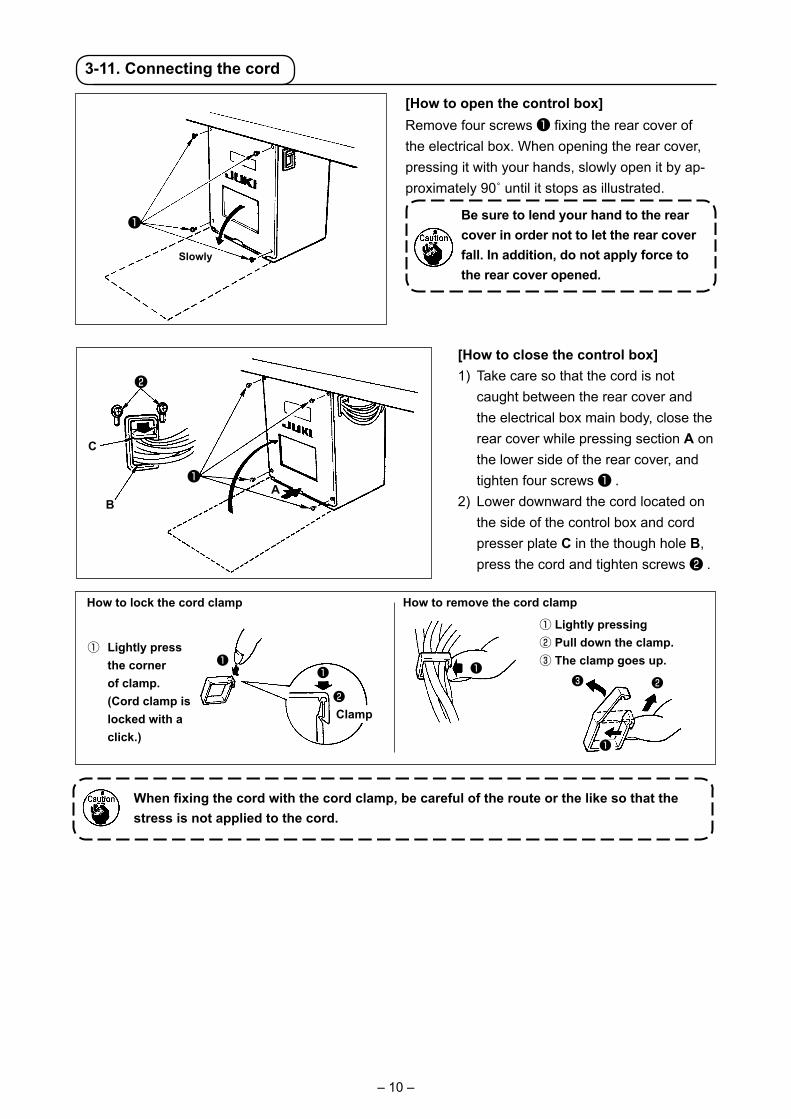
3-11. Connecting the cord
Slowly
❶
[How to open the control box]Remove four screws ❶ fixing the rear cover of the electrical box. When opening the rear cover, pressing it with your hands, slowly open it by ap-proximately 90˚ until it stops as illustrated.
Be sure to lend your hand to the rear cover in order not to let the rear cover fall. In addition, do not apply force to the rear cover opened.
[How to close the control box]1) Take care so that the cord is not
caught between the rear cover and the electrical box main body, close the rear cover while pressing section A on the lower side of the rear cover, and tighten four screws ❶ .
2) Lower downward the cord located on the side of the control box and cord presser plate C in the though hole B, press the cord and tighten screws ❷ .
❸❶
❷
❶ ❶❷
How to remove the cord clamp
❷
AB
❶
When fixing the cord with the cord clamp, be careful of the route or the like so that the stress is not applied to the cord.
C
How to lock the cord clamp
① Lightly press the corner of clamp. (Cord clamp is locked with a click.)
① Lightly pressing② Pull down the clamp.③ The clamp goes up.
Clamp
❶

– 11 –
[Wiring diagram of circuit board]
CN16
CN14
CN38
CN40
CN39
CN53
CN47
9P
IP-420F
4P
20P
10P
CN88
26P
12P 12P
CN98
CN784P
2PCN1
2P
CN100
2PCN51
10P
Air-driven type
CN34 26P
12P
2P
2P
7PCN56
CN43
CN55
CN41
CN54
CN42
5P
4P
7P
4P
7P
4P
7P
4P
10P
CN22
FGFG
2P2P2P2P
CN1
CN2CN3CN4CN5
FGP1
P2
P3
P4
2P
12P
2P
CN85
CN52CN52
CN85 2P
2P
2P
CN2
CN3CNS
3P
Air-driven type
FG
Sewing machine headSDC p.c.b.
MAIN p.c.b.
MAIN p.c.b.
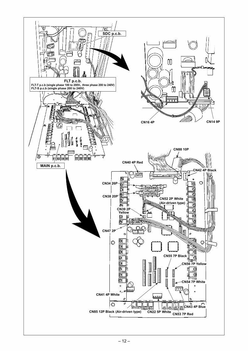
– 12 –
CN16 4P CN14 9P
SDC p.c.b.
MAIN p.c.b.
FLT p.c.b.FLT-T p.c.b (single phase 100 to 200V、three phase 200 to 240V)FLT-S p.c.b (single phase 200 to 240V)
CN40 4P Red
CN88 10P
CN34 26P
CN38 20P
CN47 2P
CN39 2P Yellow
CN52 2P White(Air-driven type)
CN22 5P WhiteCN85 12P Black (Air-driven type)
CN54 7P White
CN43 4P Blue
CN42 4P Black
CN55 7P Black
CN56 7P Yellow
CN41 4P White
CN53 7P Red

– 13 –
3-12. Installing the motor cover
❶Install motor cover ❶ on the machine main unit with screws supplied with the machine as acces-sories.
3-13. Managing the cord
❶
1) Fix the cords with cords setting plate ❶ in the state that the cords are slack to such an extent that stress is not applied to the cords even when the machine head is tilted as shown in the figure.
Slack
2) Secure the cable to be put into the POWER BOX with an internal cable clip ❷ .
❷
– 14 –
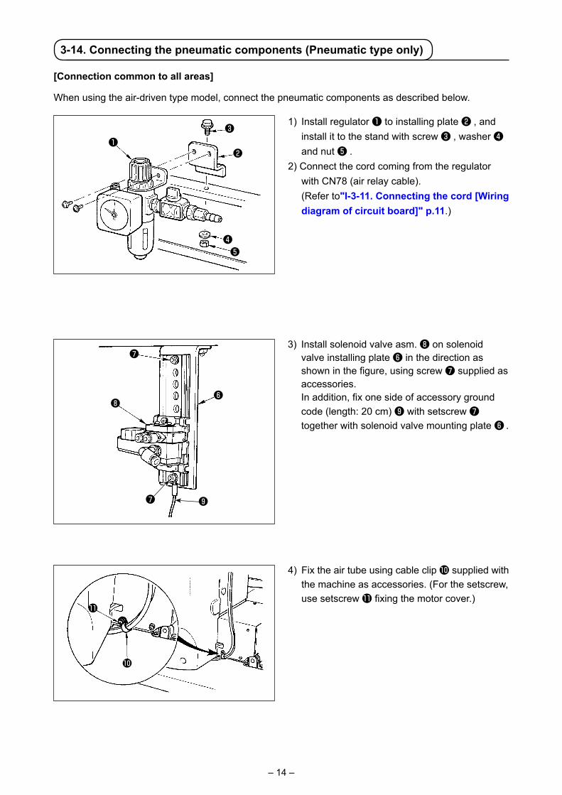
4) Fix the air tube using cable clip � supplied with the machine as accessories. (For the setscrew, use setscrew � fixing the motor cover.)
3) Install solenoid valve asm. ❽ on solenoid valve installing plate ❻ in the direction as shown in the figure, using screw ❼ supplied as accessories.
In addition, fix one side of accessory ground code (length: 20 cm) ❾ with setscrew ❼ together with solenoid valve mounting plate ❻ .
3-14. Connecting the pneumatic components (Pneumatic type only)
1) Install regulator ❶ to installing plate ❷ , and install it to the stand with screw ❸ , washer ❹ and nut ❺ .
2) Connect the cord coming from the regulator with CN78 (air relay cable).
(Refer to"I-3-11. Connecting the cord [Wiring diagram of circuit board]" p.11.)
❶❷
❸
❹❺
[Connection common to all areas]
When using the air-driven type model, connect the pneumatic components as described below.
�
�
❽❻
❼
❾❼

– 15 –
5) Install solenoid valve installing plate A asm. � on the table with two setscrews � .
Connect solenoid valve installing plate A asm � and regulator ❶ with long air tube � supplied as accessories with the machine.
In addition, fix the other side of ground cord ❾ (length: 20 cm) which has been attached in the aforementioned Step 3), with screw A which is secured with joint, together with the joint. Then, fix one side of accessory ground cord � (length: 80 cm) with screw B which fixes the joint, together with the joint.
Attach the relevant components referring to the illustrations.
Table
6) Fix the other side of ground cord � (length: 80 cm) on the bottom section inside the control box, using accessory M4 screw � .
�
❻
�
�
�
❾
�B
A
�
�
– 16 –
❽
�
�
�
�
�
�
Connector CN1
Air tube1A
Air tube1B
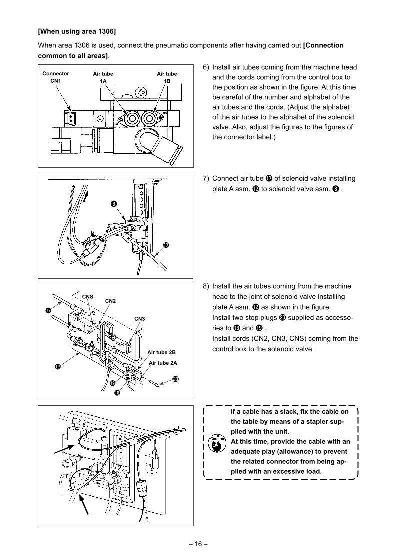
6) Install air tubes coming from the machine head and the cords coming from the control box to the position as shown in the figure. At this time, be careful of the number and alphabet of the air tubes and the cords. (Adjust the alphabet of the air tubes to the alphabet of the solenoid valve. Also, adjust the figures to the figures of the connector label.)
7) Connect air tube � of solenoid valve installing plate A asm. � to solenoid valve asm. ❽ .
[When using area 1306]
When area 1306 is used, connect the pneumatic components after having carried out [Connection common to all areas].
Air tube 2B
8) Install the air tubes coming from the machine head to the joint of solenoid valve installing plate A asm. � as shown in the figure.
Install two stop plugs � supplied as accesso-ries to � and � .
Install cords (CN2, CN3, CNS) coming from the control box to the solenoid valve.
If a cable has a slack, fix the cable on the table by means of a stapler sup-plied with the unit.At this time, provide the cable with an adequate play (allowance) to prevent the related connector from being ap-plied with an excessive load.
CN3
Air tube 2A
CN2CNS
– 17 –
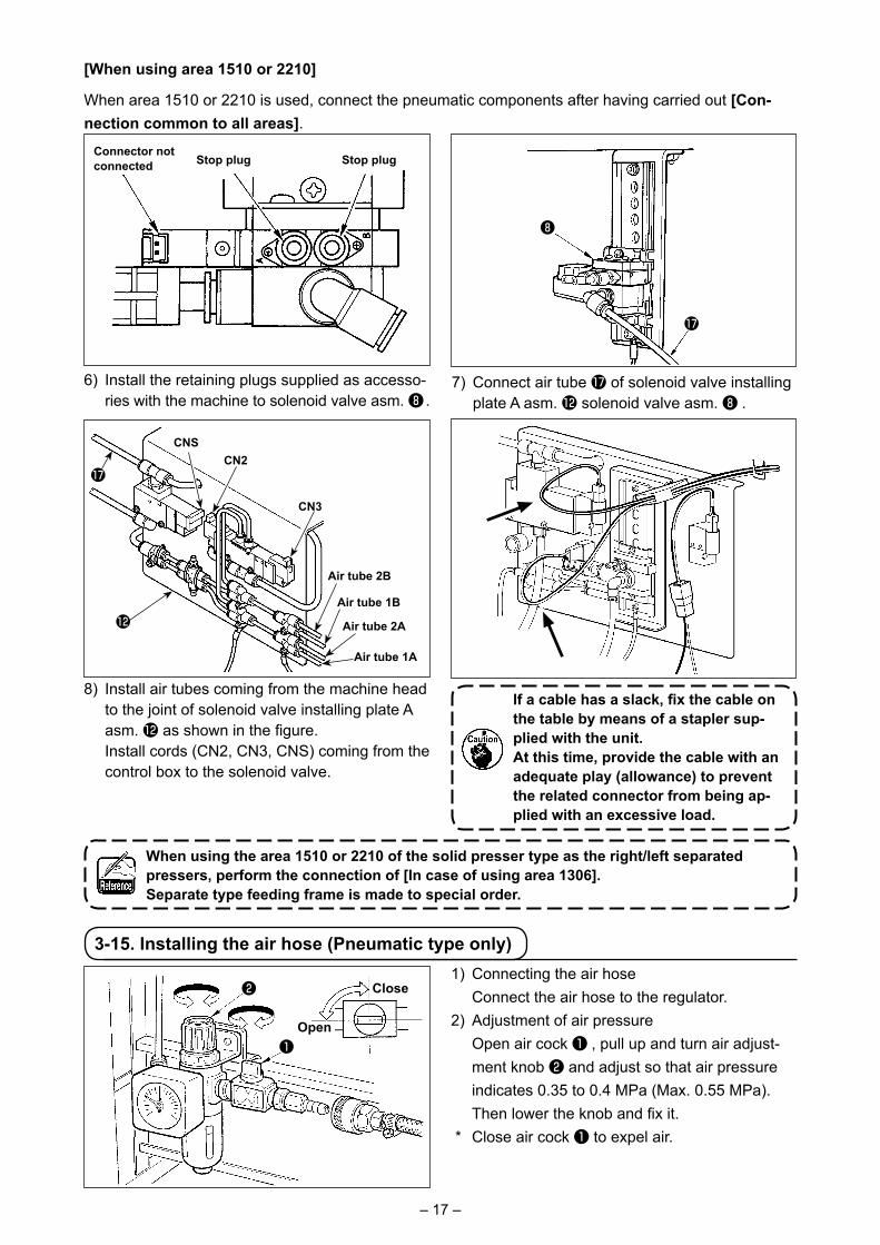
[When using area 1510 or 2210]
When area 1510 or 2210 is used, connect the pneumatic components after having carried out [Con-nection common to all areas].
Connector not connected Stop plug
6) Install the retaining plugs supplied as accesso-ries with the machine to solenoid valve asm. ❽ .
7) Connect air tube � of solenoid valve installing plate A asm. � solenoid valve asm. ❽ .
Stop plug
8) Install air tubes coming from the machine head to the joint of solenoid valve installing plate A asm. � as shown in the figure.
Install cords (CN2, CN3, CNS) coming from the control box to the solenoid valve.
Air tube 2A
Air tube 1A
Air tube 2B
Air tube 1B
CN3
CN2CNS
When using the area 1510 or 2210 of the solid presser type as the right/left separated pressers, perform the connection of [In case of using area 1306].Separate type feeding frame is made to special order.
If a cable has a slack, fix the cable on the table by means of a stapler sup-plied with the unit.At this time, provide the cable with an adequate play (allowance) to prevent the related connector from being ap-plied with an excessive load.
3-15. Installing the air hose (Pneumatic type only)
❶
❷ Close
Open
1) Connecting the air hose Connect the air hose to the regulator.2) Adjustment of air pressure Open air cock ❶ , pull up and turn air adjust-
ment knob ❷ and adjust so that air pressure indicates 0.35 to 0.4 MPa (Max. 0.55 MPa). Then lower the knob and fix it.
* Close air cock ❶ to expel air.
❽
�
�
�
– 18 –
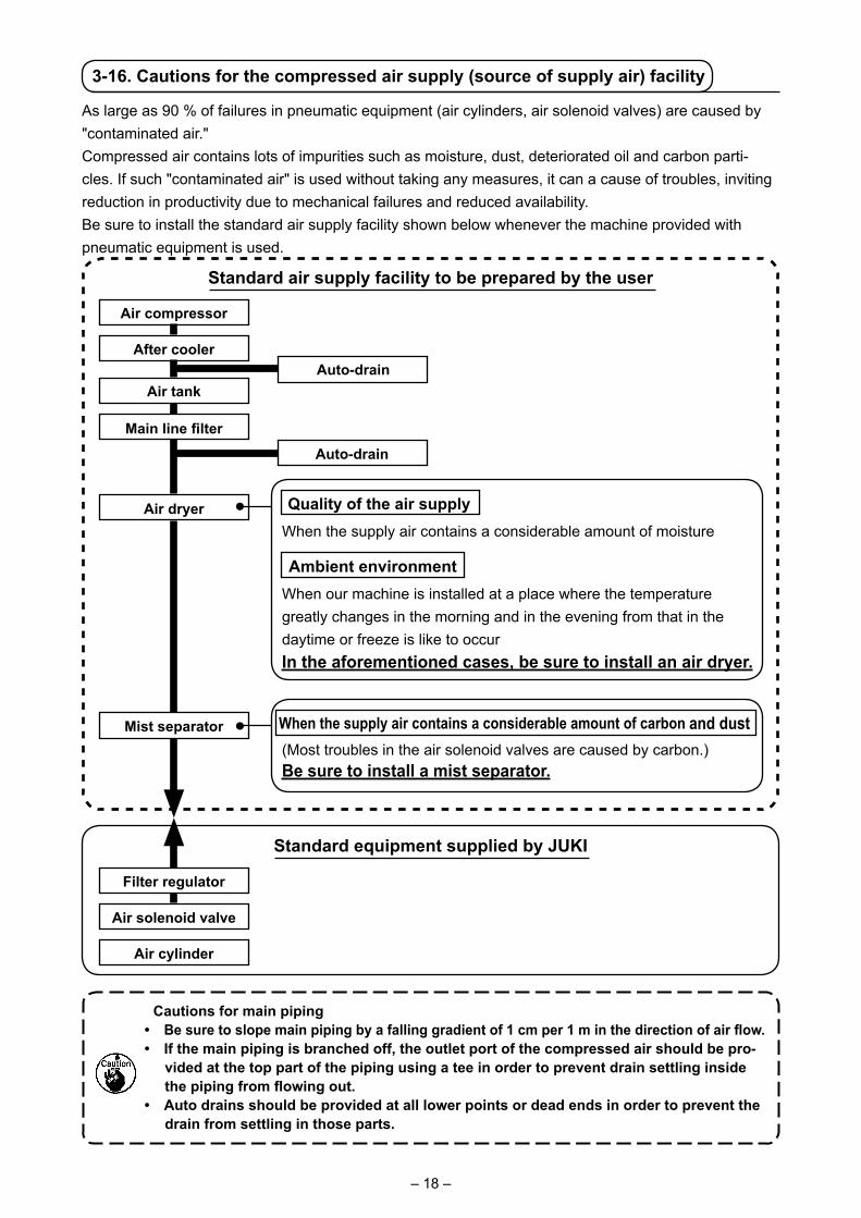
3-16. Cautions for the compressed air supply (source of supply air) facility
As large as 90 % of failures in pneumatic equipment (air cylinders, air solenoid valves) are caused by "contaminated air."Compressed air contains lots of impurities such as moisture, dust, deteriorated oil and carbon parti-cles. If such "contaminated air" is used without taking any measures, it can a cause of troubles, inviting reduction in productivity due to mechanical failures and reduced availability.Be sure to install the standard air supply facility shown below whenever the machine provided with pneumatic equipment is used.
Standard air supply facility to be prepared by the user
Standard equipment supplied by JUKI
Air compressor
After cooler
Air tank
Main line filter
Air dryer
Mist separator
Auto-drain
Auto-drain
Quality of the air supplyWhen the supply air contains a considerable amount of moisture
Ambient environmentWhen our machine is installed at a place where the temperature greatly changes in the morning and in the evening from that in the daytime or freeze is like to occurIn the aforementioned cases, be sure to install an air dryer.
(Most troubles in the air solenoid valves are caused by carbon.)Be sure to install a mist separator.
When the supply air contains a considerable amount of carbon and dust
Filter regulator
Air solenoid valve
Air cylinder
Cautions for main piping • Be sure to slope main piping by a falling gradient of 1 cm per 1 m in the direction of air flow.
• If the main piping is branched off, the outlet port of the compressed air should be pro-vided at the top part of the piping using a tee in order to prevent drain settling inside the piping from flowing out.
• Auto drains should be provided at all lower points or dead ends in order to prevent the drain from settling in those parts.

– 19 –
4. PREPARATION OF THE SEWING MACHINE
4-1. Lubrication
A
B
WARNING : Turn OFF the power before starting the work so as to prevent accidents caused by abrupt start or
the sewing machine.
Check that the place between lower line B and upper line A is filled with oil. Fill there with oil us-ing the oiler supplied with the machine as acces-sories when oil is short.
The oil tank which is filled with oil is only for lubricating to the hook portion. It is possible to reduce the oil amount when the number of rotation used is low and the oil amount in the hook portion is excessive. (Refer to "III-1-9. Amount of oil supplied to the hook" p.121 .)
1. Do not lubricate to the places other than the oil tank and the hook of Caution 2 below. Trouble of components will be caused.
2. When using the sewing machine for the first time or after an extended period of disuse, use the machine after lubricating a small amount of oil to the hook portion. (Refer to "III-1-2. Adjusting the needle-to-shuttle relation" p.115 .)
4-2. Attaching the needle
WARNING : Turn OFF the power before starting the work so as to prevent accidents caused by abrupt start or
the sewing machine.
Loosen setscrew ❶ and hold needle ❷ with the long groove facing toward you. Then fully insert it into the hole in the needle bar, and tighten setscrew ❶.
When tightening setscrew ❶ , be sure to use the screwdriver (Part No. : 40032763) supplied as accessories.Do not use L-shaped hexagon wrench key. There is a danger of breaking set-screw ❶ .
❶
❷
1.5mm
3-17. Installing the eye protection cover
WARNING : Be sure to attach this cover to protect the eyes from the disperse of needle breakage.
Use eye protection cover ❶ after securely attach-ing it on face plate cover ❸ with screw ❷.
❶
❸
❷
– 20 –
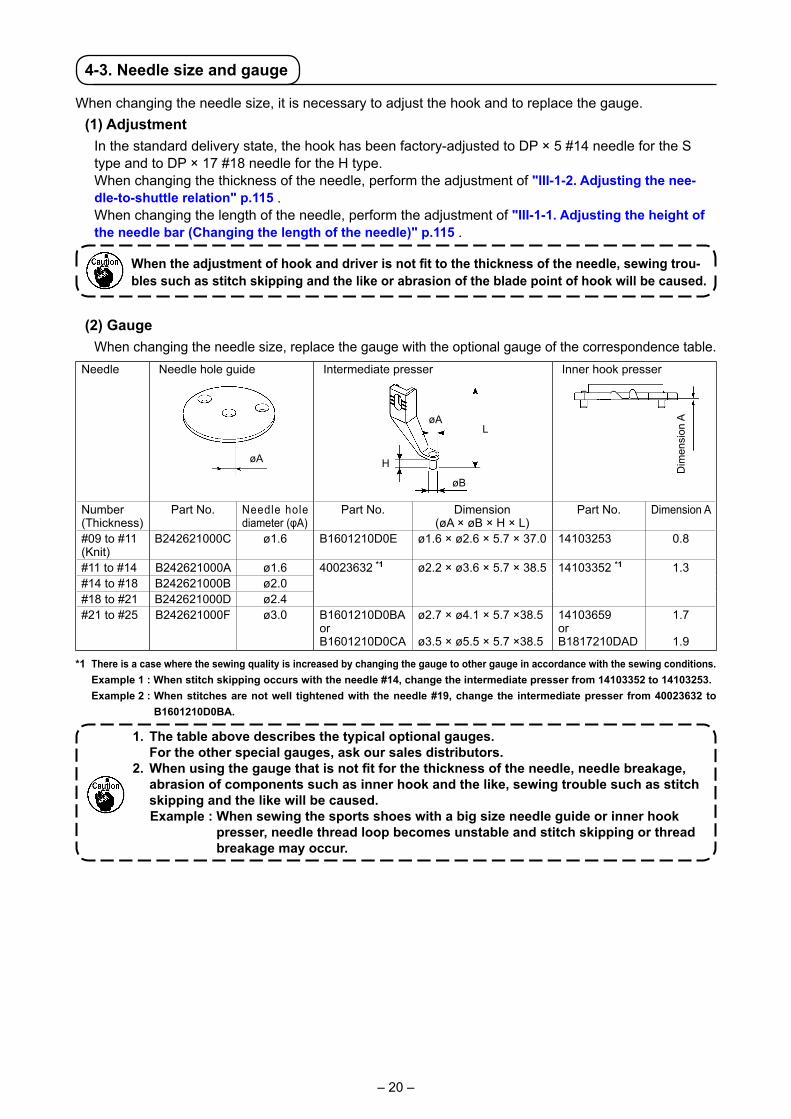
Needle Needle hole guide Intermediate presser Inner hook presser
Number (Thickness)
Part No. Needle hole diameter (φA)
Part No. Dimension (øA × øB × H × L)
Part No. Dimension A
#09 to #11 (Knit)
B242621000C ø1.6 B1601210D0E ø1.6 × ø2.6 × 5.7 × 37.0 14103253 0.8
#11 to #14 B242621000A ø1.6 40023632 *1 ø2.2 × ø3.6 × 5.7 × 38.5 14103352 *1 1.3#14 to #18 B242621000B ø2.0#18 to #21 B242621000D ø2.4#21 to #25 B242621000F ø3.0 B1601210D0BA
orB1601210D0CA
ø2.7 × ø4.1 × 5.7 ×38.5
ø3.5 × ø5.5 × 5.7 ×38.5
14103659orB1817210DAD
1.7
1.9
4-3. Needle size and gauge
When changing the needle size, it is necessary to adjust the hook and to replace the gauge.(1) Adjustment
In the standard delivery state, the hook has been factory-adjusted to DP × 5 #14 needle for the S type and to DP × 17 #18 needle for the H type.
When changing the thickness of the needle, perform the adjustment of "III-1-2. Adjusting the nee-dle-to-shuttle relation" p.115 .
When changing the length of the needle, perform the adjustment of "III-1-1. Adjusting the height of the needle bar (Changing the length of the needle)" p.115 .
When the adjustment of hook and driver is not fit to the thickness of the needle, sewing trou-bles such as stitch skipping and the like or abrasion of the blade point of hook will be caused.
(2) Gauge When changing the needle size, replace the gauge with the optional gauge of the correspondence table.
*1 There is a case where the sewing quality is increased by changing the gauge to other gauge in accordance with the sewing conditions. Example 1 : When stitch skipping occurs with the needle #14, change the intermediate presser from 14103352 to 14103253.
Example 2 : When stitches are not well tightened with the needle #19, change the intermediate presser from 40023632 to B1601210D0BA.
1. The table above describes the typical optional gauges. For the other special gauges, ask our sales distributors. 2. When using the gauge that is not fit for the thickness of the needle, needle breakage,
abrasion of components such as inner hook and the like, sewing trouble such as stitch skipping and the like will be caused.Example : When sewing the sports shoes with a big size needle guide or inner hook
presser, needle thread loop becomes unstable and stitch skipping or thread breakage may occur.
øA
L
H
øB
øA
Dim
ensi
on A
– 21 –
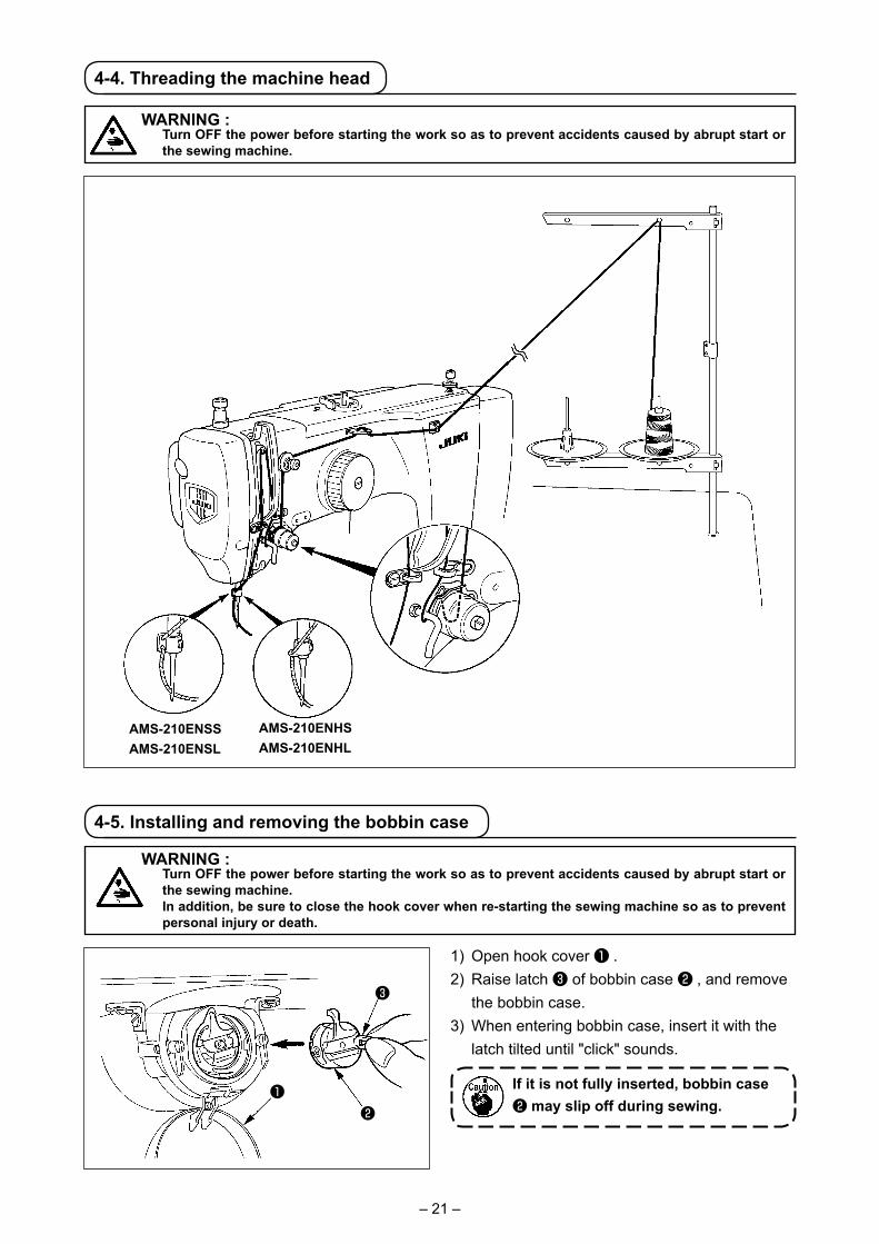
4-4. Threading the machine head
WARNING : Turn OFF the power before starting the work so as to prevent accidents caused by abrupt start or
the sewing machine.
4-5. Installing and removing the bobbin case
WARNING : Turn OFF the power before starting the work so as to prevent accidents caused by abrupt start or
the sewing machine. In addition, be sure to close the hook cover when re-starting the sewing machine so as to prevent
personal injury or death.
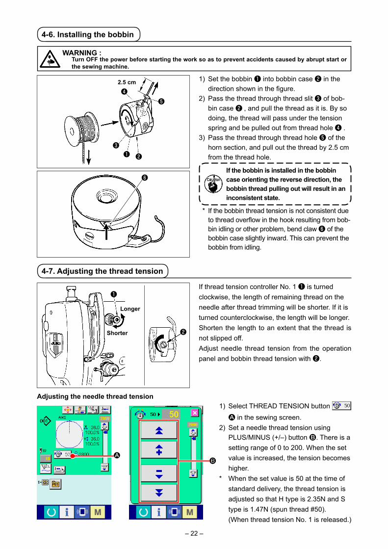
1) Open hook cover ❶ .2) Raise latch ❸ of bobbin case ❷ , and remove
the bobbin case.3) When entering bobbin case, insert it with the
latch tilted until "click" sounds.
If it is not fully inserted, bobbin case ❷ may slip off during sewing.
❶
❸
❷
AMS-210ENSSAMS-210ENSL
AMS-210ENHSAMS-210ENHL
– 22 –
4-6. Installing the bobbin
WARNING : Turn OFF the power before starting the work so as to prevent accidents caused by abrupt start or
the sewing machine.
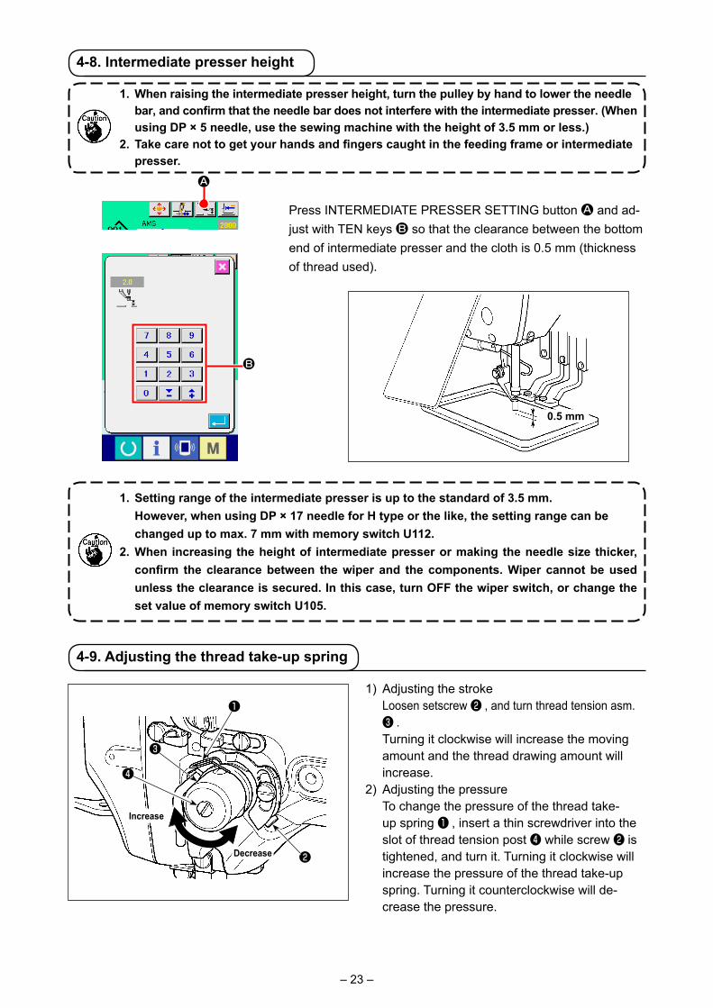
1) Set the bobbin ❶ into bobbin case ❷ in the direction shown in the figure.
2) Pass the thread through thread slit ❸ of bob-bin case ❷ , and pull the thread as it is. By so doing, the thread will pass under the tension spring and be pulled out from thread hole ❹ .
3) Pass the thread through thread hole ❺ of the horn section, and pull out the thread by 2.5 cm from the thread hole.
If the bobbin is installed in the bobbin case orienting the reverse direction, the bobbin thread pulling out will result in an inconsistent state.
* If the bobbin thread tension is not consistent due to thread overflow in the hook resulting from bob-bin idling or other problem, bend claw ❻ of the bobbin case slightly inward. This can prevent the bobbin from idling.
4-7. Adjusting the thread tension
If thread tension controller No. 1 ❶ is turned clockwise, the length of remaining thread on the needle after thread trimming will be shorter. If it is turned counterclockwise, the length will be longer.Shorten the length to an extent that the thread is not slipped off.Adjust needle thread tension from the operation panel and bobbin thread tension with ❷.
Adjusting the needle thread tension1) Select THREAD TENSION button
A in the sewing screen.2) Set a needle thread tension using
PLUS/MINUS (+/–) button B. There is a setting range of 0 to 200. When the set value is increased, the tension becomes higher.
* When the set value is 50 at the time of standard delivery, the thread tension is adjusted so that H type is 2.35N and S type is 1.47N (spun thread #50).
(When thread tension No. 1 is released.)
❺❹
2.5 cm
❶ ❷❸
❻
Longer
Shorter ❷
❶
ABB
– 23 –
4-8. Intermediate presser height
Press INTERMEDIATE PRESSER SETTING button A and ad-just with TEN keys B so that the clearance between the bottom end of intermediate presser and the cloth is 0.5 mm (thickness of thread used).
1. Setting range of the intermediate presser is up to the standard of 3.5 mm. However, when using DP × 17 needle for H type or the like, the setting range can be
changed up to max. 7 mm with memory switch U112. 2. When increasing the height of intermediate presser or making the needle size thicker,
confirm the clearance between the wiper and the components. Wiper cannot be used unless the clearance is secured. In this case, turn OFF the wiper switch, or change the set value of memory switch U105.
1. When raising the intermediate presser height, turn the pulley by hand to lower the needle bar, and confirm that the needle bar does not interfere with the intermediate presser. (When using DP × 5 needle, use the sewing machine with the height of 3.5 mm or less.)
2. Take care not to get your hands and fingers caught in the feeding frame or intermediate presser.
A
B
0.5 mm
4-9. Adjusting the thread take-up spring
1) Adjusting the stroke Loosen setscrew ❷ , and turn thread tension asm.
❸ . Turning it clockwise will increase the moving
amount and the thread drawing amount will increase.
2) Adjusting the pressure To change the pressure of the thread take-
up spring ❶ , insert a thin screwdriver into the slot of thread tension post ❹ while screw ❷ is tightened, and turn it. Turning it clockwise will increase the pressure of the thread take-up spring. Turning it counterclockwise will de-crease the pressure.
❷
❶
❹
❸
Decrease
Increase

– 24 –
5. OPERATION OF THE SEWING MACHINE
5-1. Sewing
1) Set a workpiece on the sewing machine. 2) When pedal switch A is depressed, the right-
hand presser comes down, and when it is depressed again, the presser goes up. When pedal switch B is depressed, the left-hand presser comes down, and when it is depressed again, the presser goes up.
3) Depress the pedal switch C after the feeding frame has come down and the sewing machine will start sewing.
4) After the sewing machine completes sewing, the needle point will return to the start point and the feeding frame will go up.
1) Set a workpiece on the sewing machine. 2) Depress the pedal switch A, and the feeding
frame will come down. Depress it again, and the feeding frame will go up.
3) Depress the pedal switch B after the feeding frame has come down and the sewing machine will start sewing.
4) After the sewing machine completes sewing, the needle point will return to the start point and the feeding frame will go up.
A B C
A B
⇨
■ For the 2-pedal unit: S type (all areas)
■ For the 3-pedal unit: L type (1306)
WARNING : Be extremely careful not to depress the PEDAL switch erroneously so as to prevent accidents due
to unintentional starting of the sewing machine.
Take care not to get your hands and fingers caught in the feeding frame or intermediate presser when they are in operation. In addition, be careful not to allow your hands and fingers to hit against the work clamp since it moves at a high speed.

– 25 –
1) Set a workpiece on the sewing machine. 2) Depress the pedal switch A, and the feeding
frame will come down. Depress it again, and the feeding frame will go up.
3) Depress the pedal switch B after the feeding frame has come down and the sewing machine will start sewing.
4) After the sewing machine completes sewing, the needle point will return to the start point and the feeding frame will go up.
5-2. Needle thread clamp device
By actuating the needle thread clamp device, trouble of sewing at the high-speed start (needle thread slip-off, stitch skipping or needle thread stain) is prevented, and can reduce gathering (bird's nest) of needle thread on the wrong side of cloth while keeping stable sewing. Needle thread clamp device operates in the state that thread clamp display LED is lit, and does not operate when it goes off.
Operation ON/OFF is changed over using button. When the needle thread clamp device is OFF,
the machine automatically operates at slow-start.
When memory switch No. 35 is "1" (prohibited), the thread clamp does not work. In addi-tion, button is ineffective.
* Matters that demand special attention when using the needle thread clamp device
For the thread clamp unit, there are S type and H type in accordance with the sewing types. Refer the respective types and the contents of the memory switches that can be set to the list below.
Memory switchSewing machine typeAMS-210ENSSAMS-210ENSL
AMS-210ENHSAMS-210ENHL
Thread clamp unit type
S type
H type
U700 : Front1 : Rear (standard) 0 : Front or1 : Rear (standard)
U690 : S type (standard)
1 : H type thin thread (standard) (#50 to #8)
2 : H type intermediate3 : H type thick thread (#5 to #2)
■ For the 3-pedal unit: L type (1510 and 2210)
A B
1. When using the area 1510 with the standard method, the use of 3P pedal is the same as that of 2P pedal. Refer to [In case of 2P pedal].
When using the pedal as 3P pedal by remodeling the presser or the like, it is necessary to change the connecting procedure of the pedal and memory switches U81 and U82.
2. When the 2-step stroke function is used, the feeding frame can be stopped at an arbi-trary intermediate position.
To use the 2-step stroke function, it is necessary to change the setting of the relevant MEMORY switch. Refer to "II-2-29. USING 2-STEP STROKE FUNCTION" p.91 .

– 26 –
(1) When with thread clamp (motion), use the sewing machine after adjusting the needle thread length at the start of sewing to 40 to 50 mm. When the needle thread length is too long, the needle thread end held with the needle thread clamp may be rolled in the seams.
1) In case of with the needle thread clamp, the standard of the length of needle thread is 40 to 50 mm.
• To prevent the thread from slipping off from the needle eyelet at the beginning of sewing or to prevent stitch skipping from the first stitch
→ Adjust the length of needle thread longer within the range.
• To prevent stitch skipping within the second to tenth stitches from the beginning of sewing
→ Adjust the length of needle thread shorter within the range.
2) When the needle thread is excessively long or is handled by hand after thread changing or the like, turn OFF NEEDLE THREAD CLAMP but-ton .
(2) When the thread clamp is used, and bobbin thread at the sewing start appears on the right side of material, reduce thread tension at the sewing start (2 to 3 stitches) and bobbin thread becomes less conspicuous.
[Example of setting] Tension of 1 to 2 stitches at the sewing start is “20” when sewing tension setting is “35”.
* For setting of tension at the start of sewing, see of "II-2-8.(1) Editing the thread tension" p.44 .
1. Thread at the start of sewing may be rolled in case of some patterns. When thread is rolled in even after performing adjustment of (1) or (2), use the sewing machine with thread clamp OFF.
2. Thread clamp failure may occur in the state that thread waste is jammed in the thread clamp device. Remove the thread waste referring to
"III-1-6. Needle thread clamp device" p.120 .
1)
3)
40 to 50mm
[Memory switch settings] Change the set value of memory switch U69 in accordance with the thickness of needle thread.
Memory switch U69 has been factory-set to S type (0: S type (standard)) or H type (1: H type) (thin thread). Commendable value is Set value : 1 for thread count #50 to #8, and that is Set value : 3 for thread count #5 to #2. (The value will change in accordance with the kind and thickness of the actual thread and the kinds of materials to be sewn. Set the value by adjusting to the state of needle thread on the wrong side of materials.)
In addition, it is possible to select the thread clamp position by means of memory switch U70. When the thread slipping off from the needle eyelet at the beginning of sewing or stitch skipping from the first stitch occurs, set the set value to 0 : Front and use the machine.
3) When needle thread held with the needle thread clamp is rolled in the seams, when error has oc-curred, or when needle thread is held entangled with the needle thread clamp, do not forcibly draw the cloth, but cut the connected needle thread with scissors or the like. The seams cannot be broken because of the needle thread at the start of sewing.

– 27 –
1. PREFACE
* 6 kinds of service patterns are contained in the media of the accessories.
1) Kind of sewing data handled with IP-420
Pattern nameUsers' pattern
Vector format data
M3 data
Sewing standard format
DescriptionPattern that can be stored in the body.Max. 999 patterns can be registered.File that extension is ".VDT"Read from media. Max. 999 patterns can be used.Pattern data of AMS-210D seriesUsed by copying from floppy disk of AMS-210D series to media. Max. 999 patterns can be used.File that extension is ".DAT"Read from media. Max. 999 patterns can be used.
2) Using the data (M3 data) of AMS-210D series with AMS-210EN There are two ways to use M3 data with AMS-210EN.
① Reading by using IP-420 Use PC (personal computer) and copy file (¥AMS¥AMS00xxx.M3) of M3 from floppy disk of AMS-D
to ¥AMS of media. Insert the media to IP-420, and select Pattern No.xxx from M3 data.
② Changing to vector format data using PM-1 Change to the vector format data with PM-1. (For the details, refer to Help of PM-1.) Copy the changed vector format data to ¥VDATA folder of the media. Insert the media to IP-420 and select Pattern No.
ø 36 Pitch 3.6mmPattern No. 61
EHS,EHL(Vinyl leather)
EHS,EHL (Denim) ESS,ESL
ø 30 Pitch 3 mmPattern No. 62
ø 30 Pitch 2.5 mmPattern No. 63
Area
Kind
1306
ø 60 Pitch 3.6mmPattern No. 101
ø 60 Pitch 3 mmPattern No. 102
ø 60 Pitch 2.5 mmPattern No. 103
15102210
II.OPERATION SECTION (WITH REGARD TO THE PANEL)
– 28 –
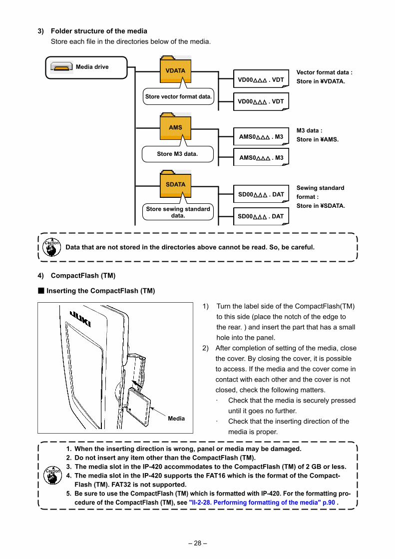
3) Folder structure of the media Store each file in the directories below of the media.
Data that are not stored in the directories above cannot be read. So, be careful.
Media drive
Store M3 data.
Vector format data : Store in ¥VDATA.
VDATA
Store vector format data.
AMS
VD00 . VDT
SD00 . DAT
SD00 . DAT
AMS0 . M3
AMS0 . M3
VD00 . VDT
SDATA
Store sewing standard data.
M3 data : Store in ¥AMS.
Sewing standard format : Store in ¥SDATA.
4) CompactFlash (TM)
1) Turn the label side of the CompactFlash(TM) to this side (place the notch of the edge to the rear. ) and insert the part that has a small hole into the panel.
2) After completion of setting of the media, close the cover. By closing the cover, it is possible to access. If the media and the cover come in contact with each other and the cover is not closed, check the following matters.・ Check that the media is securely pressed
until it goes no further.・ Check that the inserting direction of the
media is proper.
1. When the inserting direction is wrong, panel or media may be damaged. 2. Do not insert any item other than the CompactFlash (TM). 3. The media slot in the IP-420 accommodates to the CompactFlash (TM) of 2 GB or less. 4. The media slot in the IP-420 supports the FAT16 which is the format of the Compact-
Flash (TM). FAT32 is not supported. 5. Be sure to use the CompactFlash (TM) which is formatted with IP-420. For the formatting pro-
cedure of the CompactFlash (TM), see "II-2-28. Performing formatting of the media" p.90 .
Media
■ Inserting the CompactFlash (TM)
– 29 –
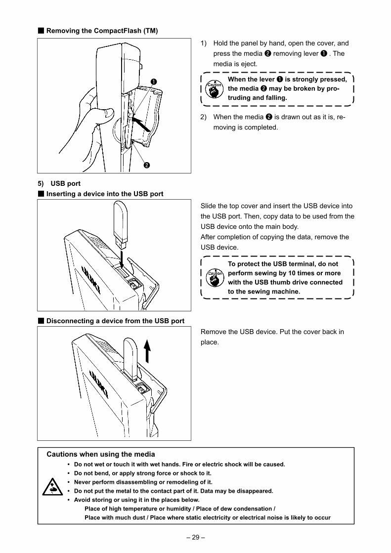
1) Hold the panel by hand, open the cover, and press the media ❷ removing lever ❶ . The media is eject.
When the lever ❶ is strongly pressed, the media ❷ may be broken by pro-truding and falling.
2) When the media ❷ is drawn out as it is, re-moving is completed.
5) USB port■ Inserting a device into the USB port
■ Removing the CompactFlash (TM)
■ Disconnecting a device from the USB port
Slide the top cover and insert the USB device into the USB port. Then, copy data to be used from the USB device onto the main body. After completion of copying the data, remove the USB device.
Remove the USB device. Put the cover back in place.
Cautions when using the media • Do not wet or touch it with wet hands. Fire or electric shock will be caused. • Do not bend, or apply strong force or shock to it.• Never perform disassembling or remodeling of it.• Do not put the metal to the contact part of it. Data may be disappeared.• Avoid storing or using it in the places below. Place of high temperature or humidity / Place of dew condensation / Place with much dust / Place where static electricity or electrical noise is likely to occur
To protect the USB terminal, do not perform sewing by 10 times or more with the USB thumb drive connected to the sewing machine.
❶
❷

– 30 –
① Precautions to be taken when handling USB devices • Do not leave the USB device or USB cable connected to the USB port while the sewing machine is in opera-
tion. The machine vibration can damage the port section resulting in loss of data stored on the USB device or breakage of the USB device or sewing machine.
• Do not insert/remove a USB device during reading/writing a program or sewing data. It may cause data breakage or malfunction. • When the storage space of a USB device is partitioned, only one partition is accessible. • Some type of the USB device may not be properly recognized by this sewing machine. • JUKI does not compensate for loss of data stored on the USB device caused by using it with this sewing ma-
chine. • When the panel displays the communication screen or pattern data list, the USB drive is not recognized even
if you insert a medium into the slot. • For USB devices and media such as CF cards, only one device/medium should be basically connected/in-
serted to/into the sewing machine. When two or more devices/media are connected/inserted, the machine will only recognize one of them. Refer to the USB specifications.
• Insert the USB connector into the USB terminal on the IP panel until it will go no further. • Do not turn the power OFF while the data on the USB flash drive is being accessed.
② USB specifications• Conform to USB 1.1 standard• Applicable devices *1 ���� Storage devices such as USB memory, USB hub, FDD and card reader• Not-applicable devices ��CD drive, DVD drive, MO drive, tape drive, etc.• Format supported ������FD (floppy disk) FAT 12
Others (USB memory, etc.), FAT 12, FAT 16, FAT 32• Applicable medium size �FD (floppy disk) 1.44MB, 720kB
Others (USB memory, etc.), 4.1MB ~ (2TB) • Recognition of drives ���For external devices such as a USB device, the device which is recognized first
is accessed. However, when a medium is connected to the built-in media slot, the access to that medium will be given the highest priority. (Example: If a medium is in-serted into the media slot even when the USB memory has already been connected to the USB port, the medium will be accessed.)
• Restriction on connection � Max. 10 devices (When the number of storage devices connected to the sewing machine has exceeded the maximum number, the 11th storage device and beyond will not be recognized unless they are once disconnected and re-connected. )
• Consumption current ���The rated consumption current of the applicable USB devices is 500 mA at the maxi-mum.
*1: JUKI does not guarantee operation of all applicable devices. Some device may not operate due to a compati-bility problem.
– 31 –
2. WHEN USING IP-420
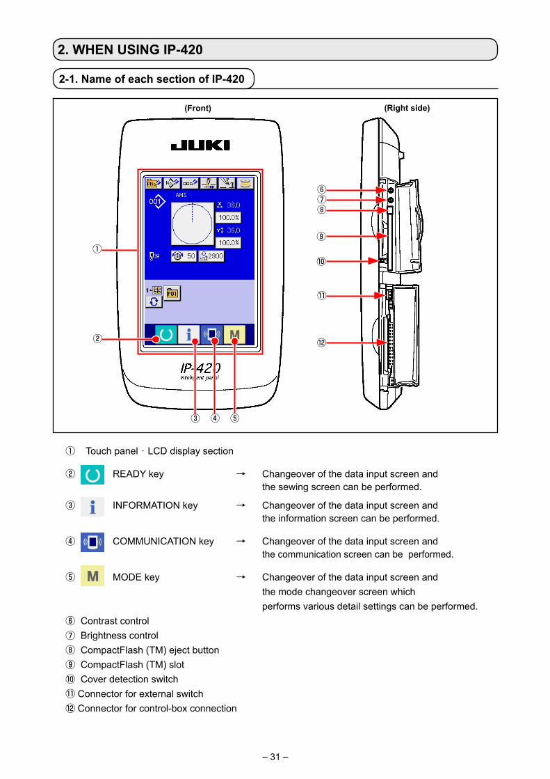
2-1. Name of each section of IP-420
(Front) (Right side)
①
③
②
④ ⑤
① Touch panel・LCD display section
② READY key → Changeover of the data input screen and the sewing screen can be performed.
③ INFORMATION key → Changeover of the data input screen and the information screen can be performed.
④ COMMUNICATION key → Changeover of the data input screen and the communication screen can be performed.
⑤ MODE key → Changeover of the data input screen and the mode changeover screen which
performs various detail settings can be performed.⑥ Contrast control ⑦ Brightness control⑧ CompactFlash (TM) eject button⑨ CompactFlash (TM) slot⑩ Cover detection switch⑪ Connector for external switch⑫ Connector for control-box connection
⑪
⑦
⑫
⑧
⑨
⑥
⑩
– 32 –
2-2. Buttons to be used in common
The buttons which perform common operations in each screen of IP-420 are as follows :
CANCEL button → This button closes the pop-up screen. In case of the data change screen, the data being
changed can be cancelled.
ENTER button → This button determines the changed data.
UP SCROLL button → This button scrolls the button or the display in the upward direction.
DOWN SCROLL button → This button scrolls the button or the display in the downward direction.
RESET button → This button performs the release of error.
NUMERAL INPUT button → This button displays ten keys and input of numerals can be performed.
CHARACTER INPUT button → This button displays the character input screen. → Refer to "II-2-14. Naming users’ pattern" p.54 .
RESSER LOWERING button → Presser is lowered, and the presser lowering screen is displayed. To lift presser, press presser lift button displayed in the presser lowering screen.
Bobbin winder button → Bobbin thread winding is performed. → Refer to "II-2-11. Winding bobbin thread" p.49 .
– 33 –
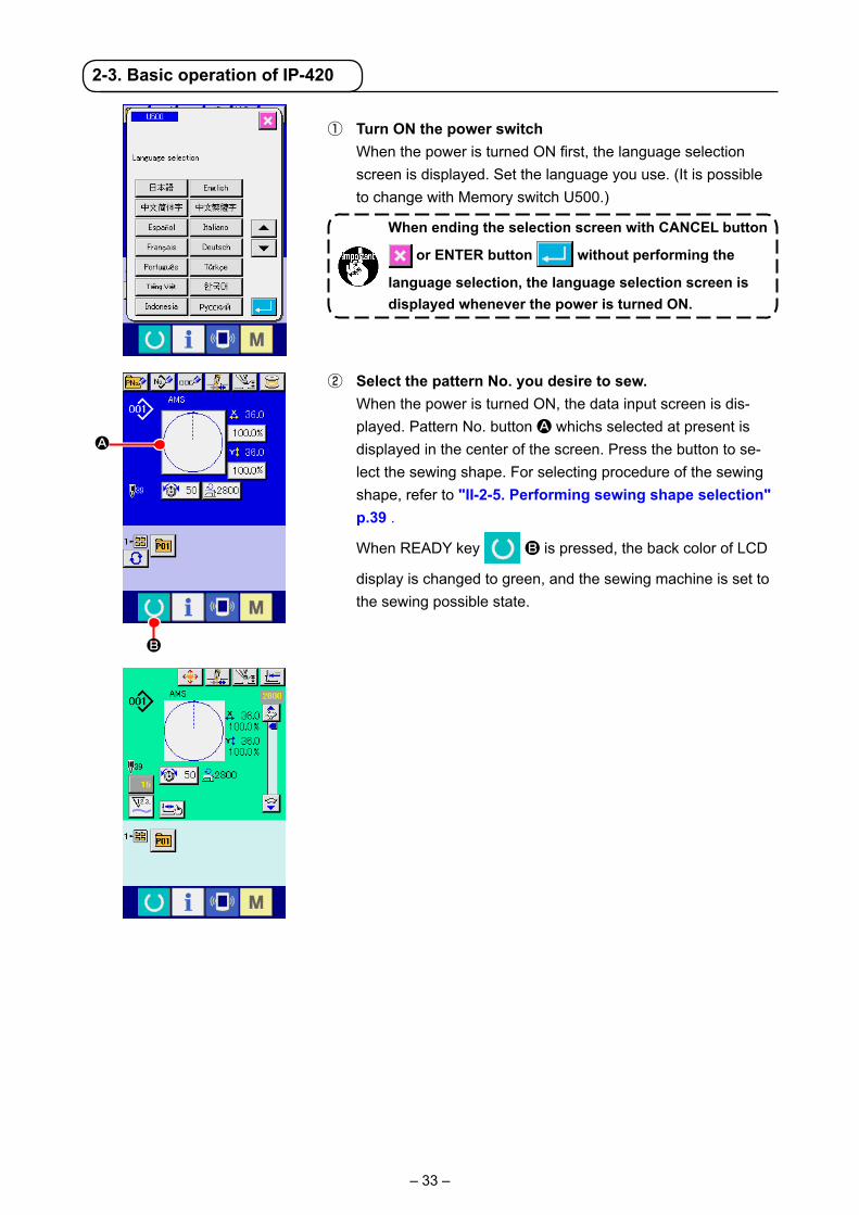
① Turn ON the power switch When the power is turned ON first, the language selection
screen is displayed. Set the language you use. (It is possible to change with Memory switch U500.)
When ending the selection screen with CANCEL button
or ENTER button without performing the
language selection, the language selection screen is displayed whenever the power is turned ON.
② Select the pattern No. you desire to sew. When the power is turned ON, the data input screen is dis-
played. Pattern No. button A whichs selected at present is displayed in the center of the screen. Press the button to se-lect the sewing shape. For selecting procedure of the sewing shape, refer to "II-2-5. Performing sewing shape selection" p.39 .
When READY key B is pressed, the back color of LCD
display is changed to green, and the sewing machine is set to the sewing possible state.
2-3. Basic operation of IP-420
A
B
– 34 –
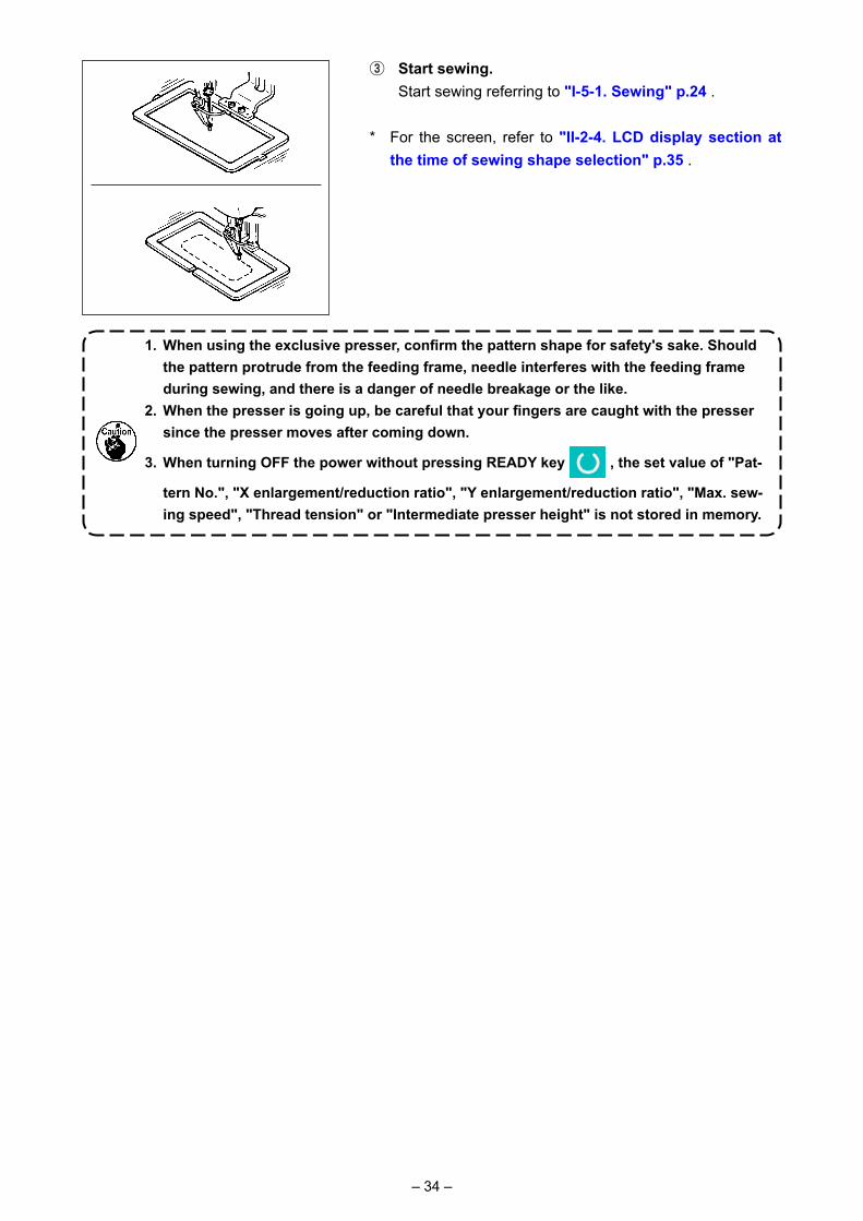
③ Start sewing. Start sewing referring to "I-5-1. Sewing" p.24 .
* For the screen, refer to "II-2-4. LCD display section at the time of sewing shape selection" p.35 .
1. When using the exclusive presser, confirm the pattern shape for safety's sake. Should the pattern protrude from the feeding frame, needle interferes with the feeding frame during sewing, and there is a danger of needle breakage or the like.
2. When the presser is going up, be careful that your fingers are caught with the presser since the presser moves after coming down.
3. When turning OFF the power without pressing READY key , the set value of "Pat-
tern No.", "X enlargement/reduction ratio", "Y enlargement/reduction ratio", "Max. sew-ing speed", "Thread tension" or "Intermediate presser height" is not stored in memory.
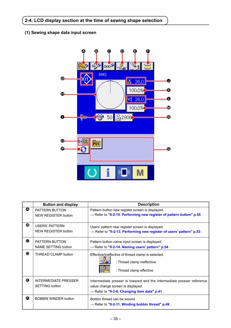
– 35 –
(1) Sewing shape data input screen
A
B
C
D
E
F
Button and displayPATTERN BUTTON NEW REGISTER button
USERS’ PATTERN NEW REGISTER button
PATTERN BUTTON NAME SETTING button
THREAD CLAMP button
INTERMEDIATE PRESSER SETTING button
BOBBIN WINDER button
DescriptionPattern button new register screen is displayed.→ Refer to "II-2-15. Performing new register of pattern button" p.55 .
Users’ pattern new register screen is displayed.→ Refer to "II-2-13. Performing new register of users’ pattern" p.53 .
Pattern button name input screen is displayed.→ Refer to "II-2-14. Naming users’ pattern" p.54 .
Effective/ineffective of thread clamp is selected.
: Thread clamp ineffective
: Thread clamp effective
Intermediate presser is lowered and the intermediate presser reference value change screen is displayed.→ Refer to "II-2-6. Changing item data" p.41 .
Bobbin thread can be wound.→ Refer to "II-2-11. Winding bobbin thread" p.49 .
B C D E F
G J
M
K
L
NI
O
P Q
H
A
2-4. LCD display section at the time of sewing shape selection

– 36 –
G
H
I
J
K
L
M
N
O
P
Q
Button and displaySEWING SHAPE NO. display
SEWING SHAPE SELECTIONbutton
NEEDLE THREAD TENSION SETTING button
X ACTUAL SIZE VALUE display
X SCALE RATE SETTING button
Y ACTUAL SIZE VALUE display
Y SCALE RATE SETTING button
MAX. SPEED LIMITATION
FOLDER NO. display
FOLDER SELECTION button
PATTERN REGISTER button
DescriptionKind and No. of the sewing shape being selected at present is displayed.There are 4 kinds below of the kinds of sewing shape. : Users' pattern
: Vector format data
: M3 data
: Sewing standard format
* Be sure to use the media that has been formatted with IP-420. For the formatting procedure of the media, refer to "II-2-28. Performing formatting of the media" p.90 .
Sewing shape being selected at present is displayed on this button and when the button is pressed, the sewing shape selection screen isdisplayed.→ Refer to "II-2-5. Performing sewing shape selection" p.39 .
Needle thread tension value which is set to the pattern data being selected at present is displayed on this button and when the button is pressed, the item data change screen is displayed.→ Refer to"II-2-6. Changing item data" p.41 .
Actual size value in X direction of sewing shape being selected at present is displayed.When the actual size value input is selected by setting memory switch
, X actual size value setting button is displayed.→ Refer to "II-2-6. Changing item data" p.41 .
Scale rate in X direction of sewing shape being selected at present is displayed on this button.When the scale input is set to non-selection by setting memory switch
, the button goes out and the X scale is displayed.→ Refer to "II-2-6. Changing item data" p.41 .Actual size value in Y direction of sewing shape being selected at present is displayed.When the actual size value input is selected by setting memory switch
, Y actual size value setting button is displayed.→ Refer to "II-2-6. Changing item data" p.41 .
Scale rate in Y direction of sewing shape being selected at present is displayed on this button. When the scale input is set to non-selection by setting memory switch , the button goes out and the Y scale is displayed. → Refer to "II-2-6. Changing item data" p.41 .
Maximum speed limitation which is set at present is displayed on this button and when the button is pressed, the item data change screen is displayed. (However, maximum speed limitation which is displayed is different from the maximum number of revolutions in the pattern.)→ Refer to "II-2-6. Changing item data" p.41 .
Pattern register button which is displayed indicates the folder No. which has been stored.
Folders to display the patterns are displayed in order.
PATTERN REGISTER buttons stored in O FOLDER NO display are displayed.→ Refer to "II-2-15. Performing new register of pattern button" p.55 .* This button is not displayed unless the new register to the pattern button
is performed.

– 37 –
(2) Sewing screen
A
B
C
D
Button and displayPATTERN BUTTON MOVE button
THREAD CLAMP button
INTERMEDIATE PRESSER SETTING button
RETURN TO ORIGIN button
DescriptionThe pattern button move screen is displayed.→Refer to "II-2-10. When setting of sewing product is difficult because of interruption of needle tip" p.48 .
Effective/ineffective of the thread clamp is selected.
: Thread clamp ineffective
: Thread clamp effective
Intermediate presser is lowered and the intermediate presser reference value change screen is displayed.→ Refer to "II-2-6. Changing item data" p.41 .
This button returns the presser to the start of sewing and raises the presser at the time of temporary stop.
R
A B C D
E
G
J
I
H
PNO
M
QK
F
S
L

– 38 –
E
F
G
H
I
J
K
L
M
N
O
P
Q
R
S
Button and displaySEWING SHAPE NO. display
SEWING SHAPE display
NEEDLE THREAD TENSION SETTING button
TOTAL NUMBER OF STITCHES OF SEWING SHAPE display
COUNTER VALUE CHANGE button
COUNTER CHANGE OVER button
STEP SEWING button
FOLDER NO. display
SPEED variable resistor
X SCALE RATE display
X ACTUAL SIZE VALUE display
Y ACTUAL SIZE VALUE display
Y SCALE RATE display
MAX. SPEED LIMITATION display
PATTERN REGISTER button
DescriptionKind and No. of the sewing shape being selected at present is displayed.There are 4 kinds below of the kinds of sewing shape.
: Users' pattern
: Vector format data
: M3 data
: Sewing standard format
* Be sure to use the media that has been formatted with IP-420. For the formatting procedure of the media, refer to "II-2-28. Performing formatting of the media" p.90 .
Sewing shape being selected at present is displayed.
Needle thread tension value which is set to the pattern data being selected at present is displayed on this button and when the button is pressed, the item data change screen is displayed.→ Refer to "II-2-6. Changing item data" p.41 .
Total number of stitches of the sewing shape being selected at present is displayed.
Existing counter value is displayed on this button.When the button is pressed, the counter value change screen is displayed. → Refer to "II-2-12. Using counter" p.50 .
The counter display can be changed over among the sewing counter, No. of pcs. counter and bobbin counter.→ Refer to "II-2-12. Using counter" p.50 .
Step sewing screen is displayed. Checking of the pattern shape can be performed.→ Refer "II-2-7. Checking pattern shape" p.43 .
Pattern register button which is displayed indicates the folder No. which has been stored.
Number of rotations of the sewing machine can be changed.
Scale rate in X direction of sewing shape being selected is displayed.
Actual size value in X direction of sewing shape being selected is displayed.
Actual size value in Y direction of sewing shape being selected is displayed.
Scale rate in Y direction of sewing shape being selected is displayed.
Maximum speed limitation which is set at present is displayed. However, the display is different from the maximum number of revolutions in the pattern. However, the display is different from the maximum number of revolutions in the pattern.
Pattern register buttons stored in L FOLDER NO. display are displayed.→ Refer to "II-2-15. Performing new register of pattern button" p.55 . * This button is not displayed in the initial state.

– 39 –
① Display the data input screen. Only in case of the data input screen (blue), the selection of
sewing shape can be performed. In case of the sewing screen
(green), press READY key and display the data input
screen (blue).② Call the sewing shape selection screen. Press SEWING SHAPE button A and the sewing shape
selection screen is displayed.
2-5. Performing sewing shape selection
③ Select the sewing shape. There are 4 kinds of the sewing shape.
Press SEWING SHAPE SELECTION button B.
* This button is not displayed in the initial state.
④ Determine the kind of sewing shape. There are 4 kinds below of the sewing shape. Select the kind
you desire from among them.
Pictograph Name
Users' pattern
Vector format data
M3 data
Sewing standard format
Maximum number of patterns
999
999
999
999
Select the sewing shape you desire from SEWING SHAPE SELECTION buttons E and press ENTER
F button.
The sewing shape list screen corresponding to the kind of sewing shape you selected is displayed.
When button C or D is pressed in this screen, X or Y enlarging/reducing ratio can be changed. For the details, refer to "II-2-6. Changing item data" p.41 .
Be sure to use the media that has been formatted with IP-420. For the formatting procedure of the media, refer to "II-2-28. Performing formatting of the media" p.90 .
A
F
E
BC
D
– 40 –
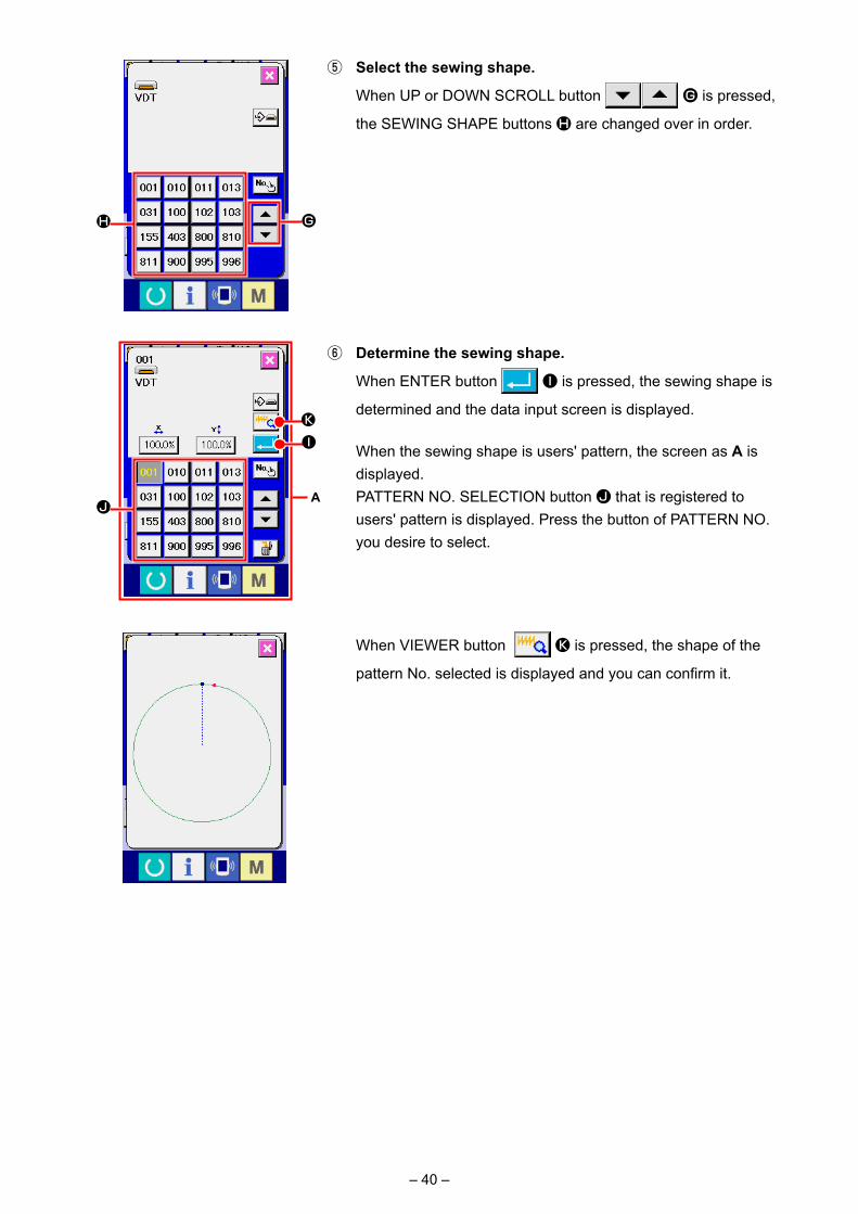
⑤ Select the sewing shape.
When UP or DOWN SCROLL button G is pressed,
the SEWING SHAPE buttons H are changed over in order.
⑥ Determine the sewing shape.
When ENTER button I is pressed, the sewing shape is
determined and the data input screen is displayed.
When the sewing shape is users' pattern, the screen as A is displayed.
PATTERN NO. SELECTION button J that is registered to users' pattern is displayed. Press the button of PATTERN NO. you desire to select.
When VIEWER button K is pressed, the shape of the
pattern No. selected is displayed and you can confirm it.
H G
J
IK
A
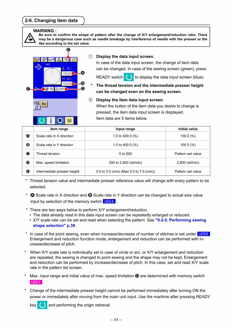
– 41 –
① Display the data input screen. In case of the data input screen, the change of item data
can be changed. In case of the sewing screen (green), press
READY switch to display the data input screen (blue).
* The thread tension and the intermediate presser height can be changed even on the sewing screen.
② Display the item data input screen. When the button of the item data you desire to change is
pressed, the item data input screen is displayed. Item data are 5 items below.
* Thread tension value and intermediate presser reference value will change with every pattern to be selected.
* A Scale rate in X direction and B Scale rate in Y direction can be changed to actual size value input by selection of the memory switch .
* There are two ways below to perform X/Y enlargement/reduction.• The data already read in this data input screen can be repeatedly enlarged or reduced.• X/Y scale rate can be set and read when selecting the pattern. See "II-2-5. Performing sewing
shape selection" p.39 .
* In case of the point sewing, even when increase/decrease of number of stitches is set under Enlargement and reduction function mode, enlargement and reduction can be performed with in-crease/decrease of pitch.
* When X/Y scale rate is individually set in case of circle or arc, or X/Y enlargement and reduction are repeated, the sewing is changed to point sewing and the shape may not be kept. Enlargement and reduction can be performed by increase/decrease of pitch. In this case, set and read X/Y scale rate in the pattern list screen.
* Max. input range and initial value of max. speed limitation D are determined with memory switch .
* Change of the intermediate presser height cannot be performed immediately after turning ON the power or immediately after moving from the main unit input. Use the machine after pressing READY
key and performing the origin retrieval.
A
BDC
E
2-6. Changing item data
Item range Input range Initial value
A Scale rate in X direction 1.0 to 400.0 (%) 100.0 (%)
B Scale rate in Y direction 1.0 to 400.0 (%) 100.0 (%)
C Thread tension 0 to 200 Pattern set value
D Max. speed limitation 200 to 2,800 (sti/min) 2,800 (sti/min)
E Intermediate presser height 0.0 to 3.5 (mm) (Max 0.0 to 7.0 (mm)) Pattern set value
WARNING : Be sure to confirm the shape of pattern after the change of X/Y enlargement/reduction ratio. There
may be a dangerous case such as needle breakage by interference of needle with the presser or the like according to the set value.

– 42 –
For example, input X scale rate.Press A to display the item data input screen.
③ Input the data. Input the value you desire with ten keys and + / – keys F.
④ Determine the data.
When ENTER button G is pressed, the data is deter-
mined. * For the other item data, the data can be changed by the
same operation. * It is possible to input X/Y value of enlargement/reduction
ratio and actual size value with one screen.
1. When turning OFF the power without pressing READY key , the set value of "Pat-
tern No.", "X enlargement/reduction ratio", "Y enlargement/reduction ratio", "Max. sew-ing speed", "Thread tension" or "Intermediate presser height" is not stored in memory.
2. When operation processing cannot be performed since the reduction ratio is excessive-ly small, E045 Pattern data error is displayed.
3. When the scale rate is changed with increase/decrease of number of stitches (pitch is fixed), mechanical control command inputted to the points other than the shape point is deleted.
H
I
When X/Y enlargement/reduction ratio, thread tension, intermedi-ate presser, adding/deleting of thread tension command, or adding/deleting of increase/decrease value of intermediate presser of us-ers’ pattern or media pattern is performed, the pattern kind section becomes change display H.
In case of change display H, the change confirmation screen is displayed at the time of the change of pattern.
When ENTER button I is pressed, the information on the current pattern is invalidated and the pattern No. is changed.
To store the changed pattern, refer to "II-2-13. Performing new register of users’ pattern" p.53 .
G
F

– 43 –
① Display the sewing screen. Display the data input screen (blue) and press READY key
A. Then the back-light of LCD changes to green and
sewing is possible. When the work clamp is in its upper posi-tion, the work clamp first comes down to its lower position and then moves to the sewing start point.
Be careful not to get your fingers caught between the work clamp and the throat plate.
④ Proceed stitching with the presser lowered. The sewing shape is displayed at the center of the screen. The
current point, sewing start position and sewing end position are respectively represented by (pink circle), (blue dot) and (pink dot).
Check the sewing shape using ONE-STITCH BACKWARD button C and ONE-STITCH FORWARD button D. When two or more commands have been entered, the feed position does not change but the command display A is moved forward and backward. When you keep pressing the ONE-STITCH FORWARD or BACKWARD button, the moving speed increases.
When the COMMAND SEARCH FORWARD button E is pressed, the feed automatically moves to the sewing end position. When the COMMAND SEARCH BACKWARD button
F is pressed, the feed automatically moves to the sew-ing start position.
To stop the feed, press button C, D, E, F, G or H. When INTERMEDIATE PRESSER button G is pressed,
the intermediate presser is raised or lowered. (This button is not displayed when MEMORY switch U103 is set at 0 (zero).)
⑤ Finish checking the shape. When PRESSER INITIAL POSITION button H is
pressed, the work clamp moves to the sewing start position and the screen is restored to the sewing screen. When CAN-CEL button I is pressed, the screen is also restored to the sewing screen. When the work clamp does not rest at the sew-ing start or end position, sewing can be started by depressing the foot switch before sewing shape checking is not completed.
The sewing machine does not start even when the foot switch is depressed with this mode.
② Display the step sewing screen.
When STEP SEWING button B is pressed, the step sewing screen is displayed.
③ Lower the presser with the foot switch.
WARNING : Make sure without fail of the contour of the sewing pattern after selection of the sewing pattern.
If the sewing pattern extends outside the work clamp feet, the needle will interfere with the work clamp.
2-7. Checking pattern shape
A
B
IA
CH
DG
EF

– 44 –
2-8. Performing modification of needle entry point
A
B
L
K
DG
E
H
IA
B J
C
F
(1) Editing the thread tension
Press STEP SEWING button A on the sewing screen to display the step sewing screen.
When it is necessary to move the feed forward or back-ward such as in the case of needle checking, the feed does not move unless the work clamp is lowered. Be sure to check the needle or other relevant operation after having lowered the work clamp.
The sewing shape is displayed at the center of the screen. The
current point, sewing start position and sewing end position are respectively represented by (pink circle), (blue dot) and (pink dot).
Press the MODE SELECT button B to select the thread tension mode.
When ONE-STITCH BACKWARD button C or FOR-WARD button D is pressed, the feed (current point ) moves backward or forward by one stitch. When two or more commands have been entered, the feed position does not change but the command display A is moved forward and backward. When you keep pressing the button C or D, the moving speed increases.
Indicated value B is the absolute value (Thread tension value + Thread tension command value).
When COMMAND SEARCH FORWARD button E or
BACKWARD button F is pressed, the feed moves for-ward or backward from the current point to reach the needle entry point where the first thread tension command is found.
To stop the feed, press button C, D, E, F, G or H.
When INTERMEDIATE PRESSER button G is pressed,
the intermediate presser is raised or lowered. (This button is not displayed when MEMORY switch U103 is set at 0 (zero).)
When PRESSER INITIAL POSITION button H is pressed, the work clamp moves to its origin and the screen is restored to the sewing screen.
When COMMAND DELETE button I is pressed, the
screen for deleting the command as shown in A is displayed.
When J is pressed, the thread tension value increase/decrease input screen is displayed.
Input a desired value on the thread tension value increase/de-crease input screen using numeric keypad and +/– keys K.
When ENTER button L is pressed, the data is con-firmed.

– 45 –
(2) Editing the intermediate presser height
Press STEP SEWING button A on the sewing screen to display the step sewing screen.
The sewing shape is displayed at the center of the screen. The current point, sewing start position and sewing end position are respectively represented by (pink circle), (blue dot) and (pink dot).
Press MODE SELECT button B to select the intermedi-ate presser mode.
When ONE-STITCH BACKWARD button C or FOR-
WARD button D is pressed, the feed (current point ) moves backward or forward by one stitch. When two or more commands have been entered, the feed position does not change but the command display A is moved forward and backward. When you keep pressing the button C or D, the moving speed increases.
Indicated value B is the absolute value (Intermediate press-er height value + Intermediate presser height increased/de-creased value).
When COMMAND SEARCH FORWARD button E or
BACKWARD button F is pressed, the feed moves for-
ward or backward from the current point to reach the needle en-try point where the first intermediate presser command is found.
To stop the feed, press button C, D, E, F, G or H.
When INTERMEDIATE PRESSER button G is pressed, the intermediate presser is raised or lowered. (This button is not displayed when MEMORY switch U103 is set at 0 (zero).)
When PRESSER INITIAL POSITION button H is pressed, the work clamp moves to its origin and the screen is restored to the sewing screen.
When COMMAND DELETE button I is pressed, the screen for deleting the command as shown in A is displayed.
When J is pressed, the intermediate presser height increase/decrease input screen is displayed. Input a desired value on this screen using numeric keypad and +/- keys K.
When ENTER button L is pressed, the data is confirmed.
1. When checking the needle, or performing the feed forward or backward, the machine fails to work un-less the presser is lowered. Use the machine after lowering the presser.
2. When the intermediate presser rests at its lower position, the movement of the intermediate presser and needle differ depending on the setting of MEMORY switch U103.
3. When increasing the height of intermediate presser or making the needle size thicker, confirm the clear-ance between the wiper and the components. Wiper cannot be used unless the clearance is secured. In this case, turn OFF the wiper switch, or change the set value of memory switch U105.
Refer to "II-3. MEMORY SWITCH DATA LIST" p.97 for the memory switch settings.
A
B
IA
B J
DG
E
H
C
F
L
K

– 46 –
When TEMPORARY STOP switch ❶ is pressed during sewing, the sewing machine can be stopped. At this time, the error screen is displayed to inform that the stop switch has been pressed.
(1) To continue performing sewing from some point in sewing
① Release the error.
Press RESET button A to release the error.
② Perform thread trimming.
Press THREAD TRIM button B to perform thread
trimming.
When PRESSER UP button G is pressed, the presser
goes up. Turn OFF the power since the operation afterwards cannot be performed.
When thread trimming is performed, INTERMEDIATE
PRESSER UP/DOWN button C, FEED BACKWARD button D, FEED FORWARD button E, and RETURN TO ORIGIN button F are displayed in the screen.
1. When the presser is raised and the operation is stopped on the way because of the trouble of for-getting to enter the bobbin case or the like, press
PRESSER UP button G and turn OFF the pow-
er.
2. PRESSER UP button G is not displayed when the presser is of pneumatic type.
③ Adjust the presser to the re-sewing position.
When FEED BACK button D is pressed, the presser
returns stitch by stitch and when FEED FORWARD button
E is pressed, it advances stitch by stitch. Move the presser to the re-sewing position.
④ Re-start the sewing. When the pedal is depressed, sewing starts again.
2-9. How to use temporary stop
A
❶
CFED
BG

– 47 –
① Release the error.
Press RESET button A to release the error.
(2) To perform re-sewing from the start
③ Return to the origin.
When RETURN TO ORIGIN button F is pressed, the
pop-up is closed, the sewing screen is displayed and the ma-chine returns to the position of the start of sewing.
④ Perform again the sewing work from the start. When the pedal is depressed, sewing starts again.
② Perform thread trimming.
Press THREAD TRIM button B to perform thread trim-ming.
When PRESSER UP button G is pressed, the presser goes up. Turn OFF the power since the operation afterwards cannot be performed.
When thread trimming is performed, INTERMEDIATE
PRESSER UP/DOWN button C, FEED BACKWARD button D, FEED FORWARD button E, and RETURN TO ORIGIN button F are displayed in the screen.
1. When the presser is raised and the operation is
stopped on the way because of the trouble of for-getting to enter the bobbin case or the like, press
PRESSER UP button G and turn OFF the pow-er.
2. PRESSER UP button G is not displayed when the presser is of pneumatic type.
A
BG
CFED
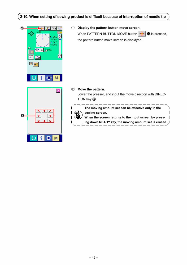
– 48 –
① Display the pattern button move screen.
When PATTERN BUTTON MOVE button A is pressed,
the pattern button move screen is displayed.
2-10. When setting of sewing product is difficult because of interruption of needle tip
② Move the pattern. Lower the presser, and input the move direction with DIREC-
TION key B.
A
B
The moving amount set can be effective only in the sewing screen.When the screen returns to the input screen by press-ing down READY key, the moving amount set is erased.

– 49 –
2-11. Winding bobbin thread
(1) When performing winding bobbin thread while performing sewing
(2) When performing winding bobbin thread only
① Display the bobbin winding screen.
Press BOBBIN WINDER button A in the data input
screen (blue) and the presser comes down. Then the bobbin winding screen is displayed.
② Start bobbin winding. Depress the start pedal, and the sewing machine rotates and
starts winding bobbin thread.
③ Stop the sewing machine.
Press STOP button B and the sewing machine stops and
returns to the normal mode. Or, depress the start pedal again
during winding bobbin and the sewing machine stops while the
bobbin thread winding mode stays as it is. Depress the start
pedal again and the bobbin winding starts again. Use this way
when winding bobbin thread around plural bobbins.
Bobbin winder does not work immediately after turning ON the power. Perform the bob-
bin winding after setting pattern No. or the like once, pressing the READY key , and
making the sewing LED light up.
Thread the bobbin winder and wind the bobbin thread onto the bobbin as illustrat-ed in the figure.
A
B
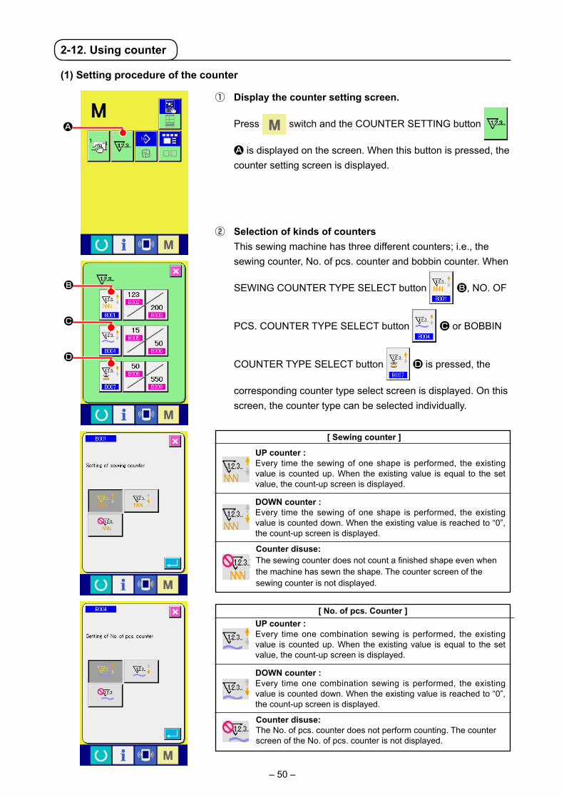
– 50 –
(1) Setting procedure of the counter
① Display the counter setting screen.
Press switch and the COUNTER SETTING button
A is displayed on the screen. When this button is pressed, the counter setting screen is displayed.
② Selection of kinds of counters This sewing machine has three different counters; i.e., the
sewing counter, No. of pcs. counter and bobbin counter. When
SEWING COUNTER TYPE SELECT button B, NO. OF
PCS. COUNTER TYPE SELECT button C or BOBBIN
COUNTER TYPE SELECT button D is pressed, the
corresponding counter type select screen is displayed. On this screen, the counter type can be selected individually.
[ Sewing counter ]
UP counter :Every time the sewing of one shape is performed, the existing value is counted up. When the existing value is equal to the set value, the count-up screen is displayed.
DOWN counter :Every time the sewing of one shape is performed, the existing value is counted down. When the existing value is reached to “0”, the count-up screen is displayed.
Counter disuse:The sewing counter does not count a finished shape even when the machine has sewn the shape. The counter screen of the sewing counter is not displayed.
[ No. of pcs. Counter ]UP counter :Every time one combination sewing is performed, the existing value is counted up. When the existing value is equal to the set value, the count-up screen is displayed.
DOWN counter :Every time one combination sewing is performed, the existing value is counted down. When the existing value is reached to “0”, the count-up screen is displayed.
Counter disuse:The No. of pcs. counter does not perform counting. The counter screen of the No. of pcs. counter is not displayed.
2-12. Using counter
A
B
C
D

– 51 –
③ Change of counter set value
Press button E for the sewing counter, button F
for the No. of pcs. counter or button G for the bobbin
counter to display the corresponding counter set value input
screen.
④ Change of counter existing value
Press button H for the sewing counter, button I
for the No. of pcs. counter or button J for the bobbin
counter to display the corresponding counter current value input screen.
Here, input the set value. When “0” is inputted in the set value, the display of count-up
screen is not performed.
[ Bobbin counter ]UP counter : The counter increases the existing value by one every time the machine has sewn 10 stitches. When the existing value is equal to the set value, the count-up screen is displayed.DOWN counter : The counter decreases from the existing value by one every time the machine has sewn 10 stitches. When the existing value is reached to “0”, the count-up screen is displayed.Counter disuse:The bobbin counter does not perform counting. The counter screen of the bobbin counter is not displayed.
E
F
G
H
I
J
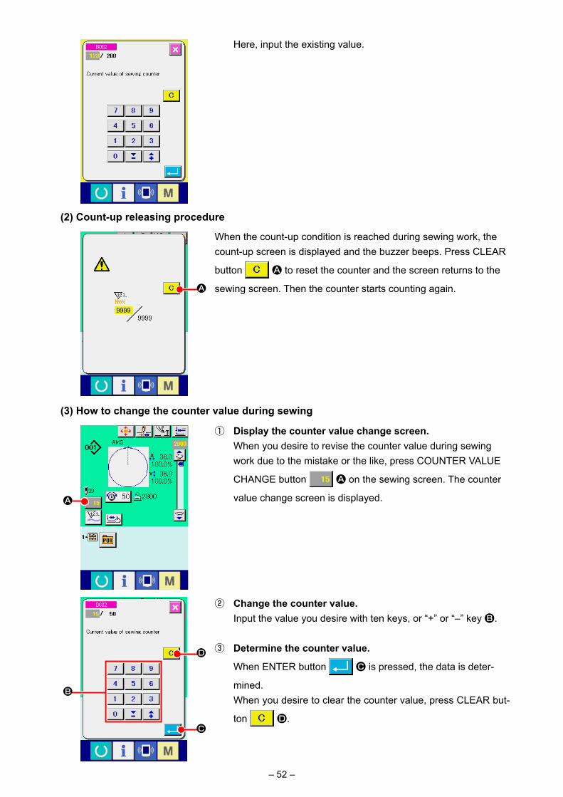
– 52 –
② Change the counter value. Input the value you desire with ten keys, or “+” or “–” key B.
③ Determine the counter value.
When ENTER button C is pressed, the data is deter-
mined. When you desire to clear the counter value, press CLEAR but-
ton D.
(3) How to change the counter value during sewing
① Display the counter value change screen. When you desire to revise the counter value during sewing
work due to the mistake or the like, press COUNTER VALUE
CHANGE button A on the sewing screen. The counter
value change screen is displayed.
(2) Count-up releasing procedure
When the count-up condition is reached during sewing work, the count-up screen is displayed and the buzzer beeps. Press CLEAR
button A to reset the counter and the screen returns to the
sewing screen. Then the counter starts counting again.A
Here, input the existing value.
A
D
B
C

– 53 –
① Display the data input screen. Only in case of the data input screen (blue), new register of the
pattern can be performed. In case of the sewing screen (green),
press READY switch and display the data input screen (blue).
② Call the new register of users’ pattern screen.
Press NEW REGISTER button A and the new register of users’ pattern screen is displayed.
2-13. Performing new register of users’ pattern
③ Input the users’ pattern No. Input the users’ pattern No. you desire to newly register with
the ten keys B. It is possible to retrieve the users’ pattern No.
which has not been registered with the + or – button
(C and D).
④ Determine the users’ pattern No.
Press ENTER button E to determine the users’ pattern
NO. to be newly registered and the data input screen at the time of users’ pattern selection is displayed.
When the existing users' pattern No. is inputted and ENTER button is pressed, the overwriting confirmation screen is dis-played.
B
E
CD
A

– 54 –
① Display the data input screen. Only in case of the data input screen (blue) at the time of pat-
tern button selection, it is possible to input the name of pattern button. In case of the sewing screen (green), press READY
switch to display the data input screen (blue).
② Call the character input screen.
When CHARACTER INPUT button A is pressed, the
character input screen is displayed.
2-14. Naming users’ pattern
③ Input the character. Press CHARACTER button B you desire to input and the
input of character can be performed. As many as 255 characters ( to and to ) and
symbols( , , , , ) can be input. The cursor
can be moved with CURSOR LEFT TRAVEL button C
and CURSOR RIGHT TRAVEL button D. When you
desire to delete the inputted character, adjust the cursor to the position of the character you desire to delete and press
DELETE button E.
④ Finish the input of character.
When ENTER button F is pressed, the input of
character is finished. After the finish, the inputted character is displayed on the upper part of the data input screen (blue).
As many as 255 characters can be input for each user’s pattern.
A
B
C
F
D E
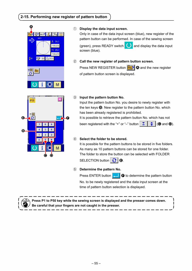
– 55 –
2-15. Performing new register of pattern button
① Display the data input screen. Only in case of the data input screen (blue), new register of the
pattern button can be performed. In case of the sewing screen
(green), press READY switch and display the data input screen (blue).
② Call the new register of pattern button screen.
Press NEW REGISTER button A and the new register
of pattern button screen is displayed.
③ Input the pattern button No. Input the pattern button No. you desire to newly register with
the ten keys B. New register to the pattern button No. which has been already registered is prohibited.
It is possible to retrieve the pattern button No. which has not
been registered with the “+” or “–” button (C and D).
④ Select the folder to be stored. It is possible for the pattern buttons to be stored in five folders.
As many as 10 pattern buttons can be stored for one folder. The folder to store the button can be selected with FOLDER
SELECTION button E.
⑤ Determine the pattern No.
Press ENTER button F to determine the pattern button
No. to be newly registered and the data input screen at the time of pattern button selection is displayed.
Press P1 to P50 key while the sewing screen is displayed and the presser comes down.Be careful that your fingers are not caught in the presser.
A
B
DC
FE

– 56 –
(1) Pattern button data input screen
A
B
C
D
E
F
Button and display PATTERN BUTTONCOPY button
PATTERN BUTTONNAME SETTING button
PATTERN BUTTONNAME display
WINDING BOBBIN button
PATTERN BUTTONNO. display
SEWING SHAPE
DescriptionPattern button copy screen is displayed.→Refer to "II-2-19. Copying pattern button" p.63 .
Pattern button name input screen is displayed.→Refer to "II-2-14. Naming users’ pattern" p.54 .
Character which is registered to the pattern button No. being selected is displayed.
Bobbin thread can be wound.→Refer to "II-2-28. Performing formatting of the media" p.90 .
Pattern button No. being selected at present is displayed on this button and when the button is pressed, the pattern button No. selection screen is displayed.→Refer to "II-2-17. Performing pattern button No. selection" p.60 .
Sewing shape which is registered to the pattern button No. being selected is displayed.
2-16. LCD display section at the time of pattern button selection
A B D
T
U
V
S
F
E
G
J
K L
Q
I
H
MNOP
C
W
R

– 57 –
G
H
I
J
K
L
M
N
O
P
Q
R
S
T
U
V
W
Button and display SEWING SHAPE NO.
TOTAL NO. OF STITCHES
2-STEP STROKE display
THREAD TENSION display
TRAVEL AMOUNT IN X DIRECTION display
TRAVEL AMOUNT IN Y DIRECTION display
X ACTUAL SIZE VALUE display
X SCALE RATE display
Y ACTUAL SIZE VALUE display
Y SCALE RATE display
MAX. SPEED LIMITATION
PATTERN BUTTON EDIT button
FOLDER NO. display
FOLDER SELECTION button
SEWING SHAPE SELECTION DATA INPUT SCREEN DISPLAY button
PATTERN button
PRESSER DOWN button
DescriptionSewing shape which is registered to the pattern button No. being selected is displayed. There are 4 kinds below of the kinds of sewing shape.
: Users' pattern
: Vector format data
: M3 data
: Sewing standard format
* Be sure to use the media that has been formatted with IP-420. For the formatting procedure of the media, refer to "II-2-28. Performing formatting of the media" p.90 .
Total number of stitches of the pattern which is registered to the pattern button No. being selected is displayed.
2-step stroke value registered to the pattern button No. being selected is displayed.
Thread tension value which is registered to the pattern button No. being selected is displayed.
Travel amount in X direction which is registered to the pattern button No. being selected is displayed.
Travel amount in Y direction which is registered to the pattern button No. being selected is displayed.
X actual size value which is registered to the pattern button No. being selected is displayed.
X scale rate which is registered to the pattern button No. being selected is displayed.
Y actual size value which is registered to the pattern button No. being selected is displayed.
Y scale rate which is registered to the pattern button No. being selected is displayed.
Maximum speed limitation which is registered to the pattern button No. being selected is displayed.
Pattern button edit screen is displayed.
Folder No. in which the displayed pattern buttons are stored is displayed.
Folders to display the pattern button are displayed in order.
Sewing shape data input screen is displayed.→ Refer to "II-2-4.(1) Sewing shape data input screen" p.35 .
Pattern buttons stored in S Folder No. are displayed.→ Refer to "II-2-15. Performing new register of pattern button" p.55 .
Presser can be lowered and the presser down screen is displayed.To raise the presser, press the presser up button which is displayed in the presser down screen.

– 58 –
(2) Sewing screen
A
B
C
D
E
Button and display 2-STEP STROKE display
PATTERN BUTTON NAME display
X SCALE RATE display
X ACTUAL SIZE VALUE display
THREAD CLAMP button
Description2-step stroke value registered to the pattern button No. during sewing is displayed.
Character which is registered to the pattern button No.being sewn is displayed.
Scale rate in X direction which is registered to the pattern button No. being sewn is displayed.
Actual size value in X direction which is registered to the pattern button No. being sewn is displayed.
Effective/ineffective of thread clamp is selected.
: Thread clamp ineffective
: Thread clamp effective
WSR
F GE
I
H
JD
K
T
QO
PU
N
M
B
L
C
VA

– 59 –
F
G
H
I
J
K
L
M
N
O
P
Q
R
S
T
U
V
W
Button and display INTERMEDIATE PRESSER SETTING button
RETURN TO ORIGIN button
PATTERN NO. display
SEWING SHAPE display
SEWING SHAPE NO. display
Y ACTUAL SIZE VALUE display
Y SCALE RATE display
TOTAL NO. OF STITCHES OF SEWING SHAPE display
NEEDLE THREAD TENSION SETTING button
TRAVEL AMOUNT IN X DIRECTION display
COUNTER VALUE CHANGE button
COUNTER CHANGEOVER button
STEP SEWING button
FOLDER NO. display
SPEED variable resistor
MAX. SPEED LIMITATION display
TRAVEL AMOUNT IN Y DIRECTION display
PATTERN REGISTER button
DescriptionThe intermediate presser is lowered and the intermediate presser reference value change screen is displayed.→ Refer to. "II-2-6. Changing item data" p.41 .
Presser is returned to the start of sewing and is raised at the time of temporary stop.
Pattern button No. being sewn is displayed.
Sewing shape being sewn is displayed.
Kind of sewing and sewing shape No. which are registered to the pattern being sewn are displayed.
Actual Y size value which is registered to the pattern button No. being selected is displayed.
Y scale rate which is registered to the pattern button No. being sewn is displayed.
Total number of stitches of sewing shape which is registered to the pattern button No. being sewn is displayed.
Needle thread tension value which is set to the pattern data being selected at present is displayed on this button and when the button is pressed, the item data change screen is displayed.→ Refer to. "II-2-6. Changing item data" p.41 .
Travel amount in X direction which is registered to the pattern button No. being sewn is displayed.
Existing counter value is displayed on this button. When the button is pressed, the counter value change screen is displayed.→ Refer to "II-2-12. Using counter" p.50 .
The counter display can be changed over among the sewing counter, No. of pcs. counter and bobbin counter.→ Refer to "II-2-12. Using counter" p.50 .
The step sewing screen is displayed. Checking the pattern shape can be performed.→ Refer to "II-(5) Setting of the skip of steps" p.72 .
Folder No. in which the displayed pattern register buttons are stored is displayed.
Number of revolutions of the sewing machine can be changed.
Maximum speed limitation which is registered to the pattern button No. being sewn is displayed.
Travel amount in Y direction which is registered to the pattern button No. being sewn is displayed.
Pattern button which is stored in S FOLDER NO. is displayed.→ Refer to "II-2-15. Performing new register of pattern button" p.55 .

– 60 –
2-17. Performing pattern button No. selection
(1) Selection from the data input screen
① Display the data input screen. In case of the data input screen (blue), it is possible to select
the pattern button No. In case of the sewing screen (green),
press READY switch to display the data input screen.
② Call the pattern button No. selection screen.
When PATTERN BUTTON NO. SELECTION button A is
pressed, the pattern button No. selection screen is displayed. Pattern button No. which is selected at present and the con-tents are displayed on the upper part of the screen, and the list of the pattern button No. buttons which have been registered is displayed on the lower part of the screen.
③ Select the pattern button No.
When UP or DOWN SCROLL button B is pressed,
pattern button No. button C which have been registered are changed over in order. The contents of sewing data which have been inputted in the pattern button No. are displayed in the button. Here, press the pattern button No. button C you desire to select.
④ Determine the pattern button No.
When ENTER button D is pressed, the pattern button
No. selection screen is closed and the selection is finished. However, the pattern buttons which are registered to the com-bination sewing cannot be deleted.
* When you desire to delete the pattern button which has been
registered, press DELETE E button. However, the pat-
tern buttons which are registered to the combination sewing cannot be deleted.
* For the pattern No. to be displayed, press FOLDER SELEC-
TION F button and pattern button Nos. which have been
stored in the specified folder are displayed in the list. When the folder No. is not displayed, all pattern Nos. which have been registered are displayed.
A
F
C B
E
D

– 61 –
(2) Selection by means of the shortcut button
① Display the data input screen or the sewing screen. When the pattern is registered to the folder, pattern buttons A
are surely displayed on the lower side of the screen of the data input screen or sewing screen.
② Select the pattern No. Pattern button is displayed with every folder which is specified
when the pattern is newly created.
When FOLDER SELECTION button B is pressed, the
pattern button to be displayed is changed. Display and press the button of the pattern button No. you desire to sew. When it is pressed, the pattern button No. is selected.
WARNING : Make sure without fail of the contour of the sewing pattern after selection of the sewing pattern.
If the sewing pattern extends outside the work clamp feet, the needle will interfere with the work clamp.
A
B
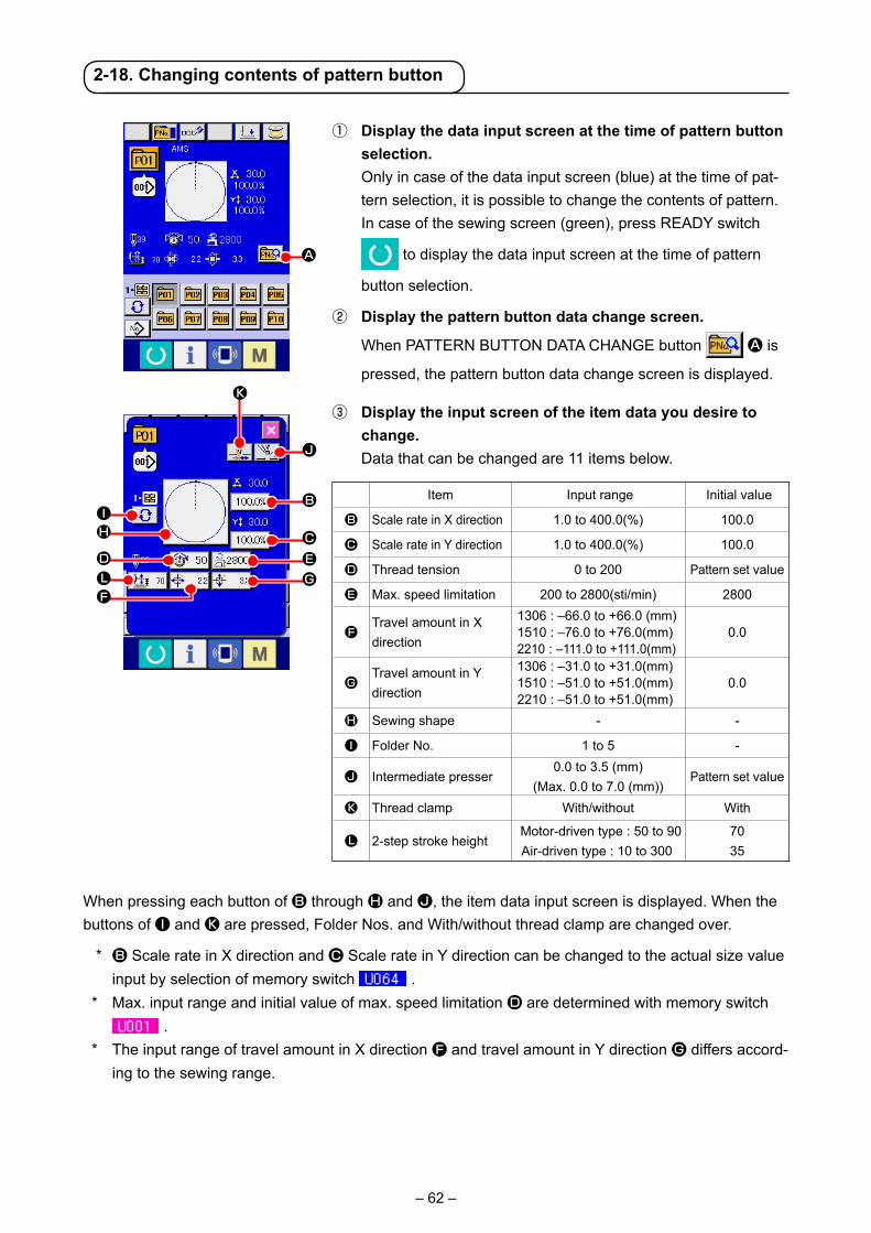
– 62 –
2-18. Changing contents of pattern button
① Display the data input screen at the time of pattern button selection.
Only in case of the data input screen (blue) at the time of pat-tern selection, it is possible to change the contents of pattern. In case of the sewing screen (green), press READY switch
to display the data input screen at the time of pattern
button selection.
② Display the pattern button data change screen.
When PATTERN BUTTON DATA CHANGE button A is
pressed, the pattern button data change screen is displayed.
When pressing each button of B through H and J, the item data input screen is displayed. When the buttons of I and K are pressed, Folder Nos. and With/without thread clamp are changed over.
* B Scale rate in X direction and C Scale rate in Y direction can be changed to the actual size value input by selection of memory switch .
* Max. input range and initial value of max. speed limitation D are determined with memory switch .
* The input range of travel amount in X direction F and travel amount in Y direction G differs accord-ing to the sewing range.
③ Display the input screen of the item data you desire to change.
Data that can be changed are 11 items below.
A
H
D
I
LF
B
CEG
J
K
Item Input range Initial value
B Scale rate in X direction 1.0 to 400.0(%) 100.0
C Scale rate in Y direction 1.0 to 400.0(%) 100.0
D Thread tension 0 to 200 Pattern set value
E Max. speed limitation 200 to 2800(sti/min) 2800
FTravel amount in X direction
1306 : –66.0 to +66.0 (mm)1510 : –76.0 to +76.0(mm)2210 : –111.0 to +111.0(mm)
0.0
GTravel amount in Y direction
1306 : –31.0 to +31.0(mm)1510 : –51.0 to +51.0(mm)2210 : –51.0 to +51.0(mm)
0.0
H Sewing shape - -
I Folder No. 1 to 5 -
J Intermediate presser0.0 to 3.5 (mm)
(Max. 0.0 to 7.0 (mm))Pattern set value
K Thread clamp With/without With
L 2-step stroke height Motor-driven type : 50 to 90
Air-driven type : 10 to 3007035

– 63 –
2-19. Copying pattern button
The sewing data of the pattern button No. which has already been registered can be copied to the pat-tern button No. which is not registered. Overwriting copy of the pattern button is prohibited. When you desire to overwrite, perform it after deleting the pattern button once.→ Refer to "II-2-17. Performing pattern button No. selection" p.60 .
① Display the data input screen. Only in case of the data input screen (blue) at the time of
pattern button selection, it is possible to copy. In case of the
sewing screen (green), press READY switch to display the data input screen (blue).
② Call the pattern copy screen.
When PATTERN BUTTON COPY button A is pressed,
the pattern button copy (copy source selection) screen is dis-played.
④ Determine the change of item data. For example, input X scale rate. Press B to display
the item data input screen. Input the value you desire with the
ten keys or + or – key K. When ENTER button L is
pressed, the data is determined.
⑤ Close the pattern button data change screen.
When the change is over, press CLOSE button M. The
pattern button data change screen is closed and the screen returns to the data input screen.
* It can be performed to change the other item data by the same operation.
M
L
K
A
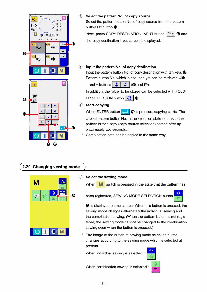
– 64 –
③ Select the pattern No. of copy source. Select the pattern button No. of copy source from the pattern
button list button B.
Next, press COPY DESTINATION INPUT button C and
the copy destination input screen is displayed.
④ Input the pattern No. of copy destination. Input the pattern button No. of copy destination with ten keys D.
Pattern button No. which is not used yet can be retrieved with
– and + buttons (F and E).
In addition, the folder to be stored can be selected with FOLD-
ER SELECTION button G.
⑤ Start copying.
When ENTER button H is pressed, copying starts. The
copied pattern button No. in the selection state returns to the pattern button copy (copy source selection) screen after ap-proximately two seconds.
* Combination data can be copied in the same way.
2-20. Changing sewing mode
① Select the sewing mode.
When switch is pressed in the state that the pattern has
been registered, SEWING MODE SELECTION button
A is displayed on the screen. When this button is pressed, the sewing mode changes alternately the individual sewing and the combination sewing. (When the pattern button is not regis-tered, the sewing mode cannot be changed to the combination sewing even when the button is pressed.)
* The image of the button of sewing mode selection button changes according to the sewing mode which is selected at present.
When individual sewing is selected :
When combination sewing is selected :
C
B
A
D
G
FE
H

– 65 –
2-21. LCD display section at the time of combination sewing
The sewing machine is capable of sewing in order by combining the plural pattern data. As many as 30 patterns can be inputted. Use this function when sewing plural different shapes on the sewing product. In addition, it is possible to register as many as 20 of the combination sewing data. Use this function for new creation and copying in case of need.→ Refer to "II-2-15. Performing new register of pattern button" p.55 and "II-2-19. Copying pattern button" p.63 .
(1) Pattern input screen
A
B
C
D
E
F
Button and displayCOMBINATION DATANEW REGISTER button
COMBINATION DATA COPY button
COMBINATION DATA NAME INPUT button
COMBINATION DATA NAME display
PRESSER DOWN button
BOBBIN WINDING
DescriptionCombination data No. new register screen is displayed.→ Refer to "II-2-15. Performing new register of pattern button" p.55 .
Combination pattern No. copy screen is displayed.→ Refer to "II-2-19. Copying pattern button" p.63 .
Combination data name input screen is displayed.→ Refer to "II-2-14. Naming users’ pattern" p.54 .
Name which is inputted in the combination data being selected is displayed.
Presser can be lowered and the presser down screen is displayed. To raise the presser, press the presser up button displayed in the presser down screen.
Bobbin thread can be wound.→ Refer to "II-2-28. Performing formatting of the media" p.90 .
A B C E F
JD
M
N
K
L
P
I
G
H Q
O

– 66 –
Button and display Description
G COMBINATION DATA NO. SELECTION button
Combination data No. being selected is displayed in the button. When the button is pressed, the combination data No. selection screen is displayed.
H SEWING ORDER display Sewing order of the inputted pattern data is displayed. When the screen is changed over to the sewing screen, the pattern which is sewn first is displayed in blue color.* As many as the number of inputted patterns is displayed in H and I,
display and button.
I PATTERN SELECTION button Pattern No., shape, number of stitches, etc. which are registered in H SEWING ORDER are displayed on the button.The sewing machine operates as described below when this button is pressed:In the case O is the pattern registration mode : The pattern select screen is displayed.→ Refer to "II-2-22.(2) Creating procedure of the combination data" p.70.In the case O is the skip select mode : The sewing of each step is changed over between "Skip" ⇔ "Not skip".→ Refer to "II-2-22.(5) Setting of the skip of steps" p.72.
J NEXT PAGE DISPLAY button This button is displayed when the number of patterns registered to combination data has reached eight or more.
K UP SCROLL button The pattern No. which is previous to the current one is selected.
L DOWN SCROLL button The pattern No. which is next to the current one is selected.
M STEP INSERT button A step is inserted before the pattern No. which is being selected.
N STEP DELETE button A step which is being selected is delete.
O Mode changeover button Every time this button is pressed, the mode is changed over between the pattern registration mode and the skip setting mode.
: Pattern registration mode : Skip setting mode
P All-skip reset button All steps registered in combination data are set to "Not skip".→ Refer to "II-2-22.(5) Setting of the skip of steps" p.72.
Q All skip button All steps registered in combination data are set to "Skip".→ Refer to "II-2-22.(5) Setting of the skip of steps" p.72.

– 67 –
(2) Sewing screen
A
B
C
D
E
F
G
H
I
Button and displayCOMBINATION DATA NAME display
THREAD CLAMP button
PRESSER DOWN button
RETURN TO ORIGIN button
COMBINATION DATA NO. display
PATTERN BUTTON NO. display
SEWING SHAPE display
SEWING ORDER RETURN button
SEWING ORDER display
DescriptionName which is inputted in the combination data being selected is displayed.
Effective/ineffective of thread clamp is selected.
: Thread clamp ineffective
: Thread clamp effective
Presser can be lowered and the presser down screen is displayed. To raise the presser, press the presser up button displayed in the presser down screen.
This button returns the presser to the start of sewing and raises the presser when the present presser position is on the way of sewing.
Combination data No. being selected is displayed.
Pattern button No. being sewn is displayed.
Sewing shape which is registered to pattern button No. being sewn is displayed.
Pattern to be sewn can be returned by one.
Sewing order being sewn at present is displayed.
B C D
E
IK
H
F
J
GL
NM
O
PX
V
W
US
QR
A
T
Y
Z
– 68 –
Button and displaySEWING ORDER ADVANCE button
TOTAL NUMBER OF REGISTERS display
TOTAL NUMBER OF STITCHES display
THREAD TENSION display
TRAVEL AMOUNT IN X DIRECTION display
COUNTER VALUE CHANGE button
COUNTER CHANGEOVER button
X ACTUAL SIZE AMOUNT display
X SCALE RATE display
SPEED variable resistor
Y ACTUAL SIZE AMOUNT display
Y SCALE RATE display
MAX. SPEED LIMITATION display
TRAVEL AMOUNT IN Y DIRECTION display
STEP SEWING button
2-STEP STROKE display
1-STEP REPEAT button
J
K
L
M
N
O
P
Q
R
S
T
U
V
W
X
Y
Z
DescriptionPattern to be sewn can be advanced by one.
Total number of patterns which is registered to combination No. being sewn is displayed.
Total number of stitches of sewing shape being sewn is displayed.
Thread tension value which is registered to pattern button No. being sewn is displayed.
Travel amount in X direction which is registered to the pattern button No. being sewn is displayed.
Existing counter value is displayed on this button. When the button is pressed, the counter value change screen is displayed.→ Refer to "II-2-12. Using counter" p.50 .
The counter display can be changed over among the sewing counter, No. of pcs. counter and bobbin counter.→ Refer to "II-2-12. Using counter" p.50 .
Actual X size value of the sewing shape which is registered to the pattern button No. being sewn is displayed.
X scale rate of the sewing shape which is registered to the pattern button No. being sewn is displayed.
Number of revolutions of the sewing machine can be changed.
Actual Y size value of the sewing shape which is registered to the pattern button No. being sewn is displayed.
Y scale rate of the sewing shape which is registered to the pattern button No. being sewn is displayed.
Maximum speed limitation which is registered to pattern button No. being sewn is displayed.
Travel amount in Y direction which is registered to the pattern button No. being sewn is displayed.
The step sewing screen is displayed. Checking thepattern shape can be performed.→ Refer to "II-2-7. Checking pattern shape" p.43 .
2-step stroke value registered to the pattern button No. during sewing is displayed.
Enable/disable of the 1-step repetition is selected.
: 1-step repeat is disabled
: 1-step repeat is enabled

– 69 –
2-22. Performing combination sewing
(1) Selection of combination data
First, change the sewing mode to the combination sewing before performing setting. → Refer to "II-2-20. Changing sewing mode" p.64 .
① Display the data input screen. Only in case of the data input screen (pink), it is possible to
select the combination data No. In case of the sewing screen (green), press READY switch
to display the data input screen (pink).
② Call the combination data No. screen.
When COMBINATION DATA NO. button A is pressed,
the combination data No. selection screen is displayed. Com-bination data No. which is selected at present and the con-tents are displayed in the upper part of the screen, and other combination data No. buttons which have been registered are displayed in the lower part of the screen.
C
E
F
D
B
③ Select the combination data No.
When UP/DOWN button B is pressed, combination
data No. buttons C which have been registered are changed over in order.
It is also possible to display the combination data No. input
screen using NUMBER INPUT button D and input a
combination data No. directly. Here, press the combination data No. buttons C you desire to
select.
When STEP CONFIRMATION button E is pressed,
the sewing shapes of patterns which have been registered in the combination data and the like are changed over in order and displayed.
④ Determine the combination data No.
When ENTER button F is pressed, the combination
data No. selection screen is closed and the selection is fin-ished.
A

– 70 –
(2) Creating procedure of the combination data
① Display the data input screen. Only in case of the data input screen (pink) it is possible to input
the combination data. In case of the sewing screen (green),
press READY switch to display the data input screen (pink). Pattern No. has not been registered in the initial state, and the
first pattern selection button is displayed in the blank state.
② Display the pattern No. selection screen.
When PATTERN SELECTION button A is pressed, the pattern No. selection screen is displayed.
A
C B
F
ED
I
G
④ Determine the pattern No.
When ENTER button E is pressed, the pattern No. se-
lection screen is closed and the selection is finished.
⑤ Repeat steps ② through ④ as many as the number of pat-tern Nos. you desire to register.
When the first register is determined, the second pattern selec-
tion button F is displayed.
Repeat steps ② through ④ as many as the number of pattern Nos. you desire to register.
When UP or DOWN SCROLL button G is pressed,
the PATTERN NO. button can be selected. The selected PAT-
TERN NO. button is displayed in pink .
When the PATTERN NO. INSERT button H is pressed,
a step is inserted before the pattern No. being selected (dis-played in pink). When PATTERN NO. button I being dis-played is pressed to select a different pattern No., the pattern No. is changed over.
If the programmed combination data extends over two or more screens, the next screen can be displayed by means of
SCREEN SCROLL button J.
H
J
Check to be sure that the selected-mode changeover button K is set to the pattern registration mode. If the mode is not the pattern registration mode, press the selected-mode changeover button K.
③ Select the pattern No.
When UP/DOWN SCROLL button B is pressed,
pattern No. buttons C which have been registered are changed over in order.
It is also possible to display the pattern No. input screen by
means of NUMBER INPUT button D and input a pattern
No. directly. The contents of pattern data are displayed in the buttons. Here, press the pattern No. buttons you desire to select.
K

– 71 –
(3) Deleting procedure of the combination data
① Select the combination data No. Perform steps ① to ③ of "II-2-22. Performing combination
sewing" p.69 to display the combination data to be delet-ed.
② Performing deleting the combination data.
When DATA DELETION button A is pressed, the com-
bination data deletion confirmation pop-up is displayed. Here,
press ENTER button B, and the selected combination
data is deleted.
(4) Deleting procedure of the step of the combination data
① Select the combination data No. Perform steps ① to ② of “"II-2-22. Performing combination
sewing" p.69 to make the state that the combination data including the step you desire to delete has been selected.
② Display the pattern No. selection screen.
Press UP/DOWN SCROLL button A to bring the
PATTERN SELECT button for the step to be deleted under the
selected state B. Then, when STEP DELETE button
C is pressed, the data step delete popup window is dis-
played.
③ Performing deleting the step of the selected combination data.
When ENTER button D is pressed, the selected combi-
nation data step is deleted.
When the CANCEL button E is pressed, no data is delet-
ed and the screen is restored to the data input screen.
D
E
A
B
B
C
A

– 72 –
2-23. Using the simple operation mode
① sSelect the sewing mode.
When the key is pressed, SCREEN MODE SELECT
button A is displayed on the screen. When this button is
pressed, the screen mode is changed over between the nor-mal operation and the simple operation.
When the normal operation is selected:
When the simple operation is selected:
A
With IP-420, the SIMPLE OPERATION mode is available.
(5) Setting of the skip of steps
① Entering the skip setting mode
Press mode changeover button A to select skip setting
mode B.A
DE
B
C
② Pressing the button of the step to be skipped. Press button C of the step to display . The step is set to
"Skip". Another press on the button resets the skip setting. It is possible to set two or more steps to "Skip".
When all skip button E or all skip reset button D
is pressed, the skip can be set for all steps or the skip setting can be reset for all steps. Note that the sewing screen is not displayed even by pressing the set ready key when all steps are set to "Skip".
It is possible to set the skipping of sewing of a given step.If you want to skip the sewing of a certain step within the combination data, use this function.

– 73 –
2-24. LCD display when the simple operation is selected
(1) Data input screen (individual sewing)
[User’s pattern]
[Media pattern] [Direct pattern]Ⓐ Ⓑ
ⒷⒶ
F FⒸ
B C
E
M
F
NO
H
DGI
J
K
Q
P
AL

– 74 –
A THREAD CLAMP button Effective/ineffective of thread clamp is selected.
: Thread clamp ineffective
: Thread clamp effective
B PRESSER DOWN button Feeding frame and intermediate presser are lowered and the presser down screen is displayed.
C BOBBIN WINDER button Bobbin thread can be wound.→ Refer to "II-2-11. Winding bobbin thread" p.49 .
D PATTERN NO. SETTING button
Pattern No. is set. Registered pattern No. is retrieved using PLUS button J and MINUS button K.
E PATTERN TYPE SETTING button
Pattern type is specified. The pattern type is changed over among the following three different ones using PLUS button J and MINUS button K to select a desired one.
: User’s pattern : Vector form data
: M3 data : Standard format of sewing
: Direct pattern
The selected pattern type is indicated on edit data display Q.*A type to which no pattern is registered cannot be selected.
F PATTERN LIST button Pattern No. and type which are currently selected are indicated on the button.When the button is pressed, the selected pattern list screen is displayed for the pattern selection.
G NEEDLE THREAD TENSION SETTING button
The current needle thread tension reference value is indicated on the button. When the button is pressed, the thread tension reference value can be changed. During the setting procedure, the thread tension reference value is indicated on edit data display Q.The thread tension value is increased/decreased in increments of 1 using PLUS button J or MINUS button K.→ Refer to "II-2-6. Changing item data" p.41 .
H MAX SPEED LIMITATION SETTING button
The current max. speed limitation is indicated on the button. When the button is pressed, the max. speed limitation can be changed. During the setting procedure, the max. speed limitation is indicated on edit data display Q.The max. speed limitation is increased/decreased in increments of 100 sti/min using PLUS button J or MINUS button K.→ Refer to "II-2-6. Changing item data" p.41 .
I INTERMEDIATE PRESSER HEIGHT REFERENCE VALUE SETTING button
The current intermediate presser height reference value is indicated on the button. When the button is pressed, the intermediate presser height reference value can be changed. During the setting procedure, the intermediate presser height reference value is indicated on edit data display Q. The intermediate presser height reference value is increased/decreased in increments of 0.1 mm using PLUS button J or MINUS button K.→ Refer to "II-2-6. Changing item data" p.41 .
J PLUS button The value for the selected item is increased in increments of the reference unit.
K MINUS button The value for the selected item is decreased in increments of the reference unit.
L PATTERN NAME display The name of the currently selected pattern is displayed.
Button and display Description
– 75 –
Button and display DescriptionM SEWING SHAPE display The sewing shape of the currently selected pattern is displayed
N NUMBER OF STITCHES display
The number of stitches for the currently selected pattern is displayed.
O X ACTUAL SIZE VALUE display
The actual X size value of the sewing shape which is being selected is displayed. When an actual value input is selected, the X ACTUAL VALUE SETTING button is displayed according to the setting of MEMORY switch .→ Refer to "II-2-6. Changing item data" p.41 .
P Y ACTUAL SIZE VALUE display
The actual Y size value of the sewing shape which is being selected is displayed. When an actual value input is selected, the Y ACTUAL VALUE SETTING button is displayed according to the setting of MEMORY switch .→ Refer to "II-2-6. Changing item data" p.41 .
Q EDIT DATA display The data which is being edited on the currently selected edit item is displayed.* When no edit item is selected, this display is not given.
Ⓐ MEDIA PATTERN WRITE button
Data on a media pattern is written. When this button is pressed, the new media pattern registration screen is displayed.* This button is displayed when the media pattern is selected.
Ⓑ USER’S PATTERN WRITE button
Data on a user’s pattern is written. When this button is pressed, the new user’s pattern registration screen is displayed.* This button is displayed when the media pattern is selected.
Ⓒ SEWING DATA TYPE display
The type of data read from a medium is displayed.
: Vector form data
: M3 data
: Standard format of sewing* This display is given when the media pattern is selected.
A TRAVEL AMOUNT IN X DIRECTION display
The amount of travel in the X direction which is registered to the pattern button No. being selected is displayed.* This display is given when a direct pattern is selected.
B TRAVEL AMOUNT IN Y DIRECTION display
The amount of travel in the Y direction which is registered to the pattern button No. being selected is displayed.* This display is given when a direct pattern is selected.

– 76 –
A B C
P
O
D
MN
CB
Ⓐ
M A
Q
J
HI
K
L
R
E
S
F
G
[User’s pattern]
[Media pattern] [Direct pattern]
(2) Sewing screen (individual sewing)
– 77 –
A PATTERN BUTTON MOVE button
The pattern button move screen is displayed.→Refer to "II-2-10. When setting of sewing product is difficult because of interruption of needle tip" p.48 .
B THREAD CLAMP button Effective/ineffective of thread clamp is selected.
: Thread clamp ineffective
: Thread clamp effective
C PRESSER DOWN button Feeding frame and intermediate presser are lowered and the presser down screen is displayed.
D RETURN TO ORIGIN button
The work clamp is returned to the start of sewing and raised to its upper position at the time of a temporary stop.
E SHAPE CHECK button The shape of the pattern which is being selected is checked using PLUS button K or MINUS button L. The current number of stitches is indicated on edit data display S.→Refer to "II-2-7. Checking pattern shape" p.43 .
F COUNTER VALUE CHANGE button
The counter value is changed using PLUS button K or MINUS button L. The counter value is indicated on the button. When the button is pressed, G is displayed to allow the counter value to be changed.The current counter value is indicated on edit data display S.→Refer to "II-2-12. Using counter" p.50 .
G CLEAR button The counter value is cleared.* This button is displayed only when COUNTER VALUE CHANGE button F is being selected.
H NEEDLE THREAD TENSION SETTING button
The current needle thread tension reference value is indicated on the button. When the button is pressed, the reference value of the thread tension can be set.During the setting procedure, the thread tension reference value is indicated on edit data display S.The thread tension value is increased/decreased in increments of 1 using PLUS button K or MINUS button L.The thread tension can be changed even during sewing.
I INTERMEDIATE PRESSER HEIGHT REFERENCE VALUE SETTING button
The current intermediate presser height reference value is indicated on the button. When the button is pressed, the intermediate presser height reference value can be set. During the setting procedure, the intermediate presser height reference value is indicated on edit data display S. The intermediate presser height reference value is increased/decreased in increments of 0.1 mm using PLUS button K or MINUS button L.
J SPEED CHANGE button The speed of stitch of the sewing machine is indicated on the button. When the button is pressed, the speed of stitch can be changed. During the setting procedure, the current speed of the sewing machine is indicated on edit data display S.The max. speed limitation is increased/decreased in increments of 100 sti/min using PLUS button K or MINUS button L.
K PLUS button The value for the selected item is increased in increments of the reference unit or the needle is moved forward by one stitch.
L MINUS button The value for the selected item is decreased in increments of the reference unit or the needle is moved backward by one stitch.
Button and display Description
– 78 –
Button and display DescriptionM PATTERN NO./TYPE
displayThe pattern No. and type of the pattern which is being selected are displayed.
N PATTERN NAME display The name of the currently selected pattern is displayed.
O NUMBER OF STITCHES display
The number of stitches for the currently selected pattern is displayed.
P SEWING SHAPE display The sewing shape of the currently selected pattern is displayed.
Q X ACTUAL SIZE VALUE display
The actual X size value of the sewing shape which is being selected is displayed.
R Y ACTUAL SIZE VALUE display
The actual Y size value of the sewing shape which is being selected is displayed.
S EDIT DATA display The data which is being edited on the currently selected edit item is displayed.* When no edit item is selected, this display is not given.
Ⓐ SEWING DATA TYPE display
The type of data read from a medium is displayed.
: Vector form data
: M3 data
: Standard format of sewing* This display is given when the media pattern is selected.
A PATTERN LIST button Pattern No. and type which are currently selected are indicated on the button.When the button is pressed, the selected pattern list screen is displayed for the pattern selection.
B TRAVEL AMOUNT IN X DIRECTION display
The amount of travel in the X direction which is registered to the pattern button No. being selected is displayed.* This display is given when a direct pattern is selected.
C TRAVEL AMOUNT IN Y DIRECTION display
The amount of travel in the Y direction which is registered to the pattern button No. being selected is displayed.* This display is given when a direct pattern is selected.
– 79 –
(3) Data input screen (combination sewing)
A PRESSER DOWN button Feeding frame and intermediate presser are lowered and the presser down screen is displayed.
B BOBBIN WINDER button Bobbin thread can be wound.→ Refer to "II-2-11. Winding bobbin thread" p.49 .
C SEWING ORDER RETURN button
The pattern No. to be sewn first can be returned to the previous sewing order. The pattern information shown at the upper part of the screen is updated.
D SEWING ORDER ADVANCE button
The pattern No. to be sewn first can be advanced to the next sewing order.The pattern information shown at the upper part of the screen is updated.
E PATTERN No. SETTING button
Pattern No. is set. Registered pattern No. is retrieved using PLUS button G and MINUS button H.
F PATTERN LIST button Pattern No. and type which are currently selected are indicated on the button.When the button is pressed, the selected pattern list screen is displayed for the pattern selection.
G PLUS button The value for the selected item is increased in increments of the reference unit.
H MINUS button The value for the selected item is decreased in increments of the reference unit.
I SEWING ORDER display The sewing order of the currently selected pattern data is displayed.
J TOTAL NUMBER OF REGISTERS display
The total number of patterns registered to the cycle pattern which is currently being selected is displayed.
Button and display Description
A B
F
MN
G
H
K
R
OD
L
E
P Q
IJ
C
– 80 –
K PATTERN NAME display The name of the currently selected pattern is displayed.
L SEWING SHAPE display The sewing shape of the currently selected pattern is displayed.
M NUMBER OF STITCHES display
The number of stitches for the currently selected pattern is displayed.
N X ACTUAL SIZE VALUE display
The actual X size value of the currently selected pattern is displayed.
O Y ACTUAL SIZE VALUE display
The actual Y size value of the currently selected pattern is displayed.
P TRAVEL AMOUNT IN X DIRECTION display
The amount of travel in the X direction of the currently selected pattern is displayed.
Q TRAVEL AMOUNT IN Y DIRECTION display
The amount of travel in the Y direction of the currently selected pattern is displayed.
R EDIT DATA display The data which is being edited on the currently selected edit item is displayed.* When no edit item is selected, this display is not given.
Button and display Description

– 81 –
(4) Sewing screen (combination sewing)
A THREAD CLAMP button Effective/ineffective of thread clamp is selected.
: Thread clamp ineffective
: Thread clamp effective
B PRESSER DOWN button Feeding frame and intermediate presser are lowered and the presser down screen is displayed.
C RETURN TO ORIGIN button
The work clamp is returned to the start of sewing and raised to its upper position at the time of a temporary stop.
D SEWING ORDER RETURN button
The pattern to be sewn can be returned to the previous one.
E SEWING ORDER ADVANCE button
The pattern to be sewn can be advanced to the next one.
F SHAPE CHECK button The shape of the pattern which is being selected is checked using PLUS button J or MINUS button K. The current number of stitches is indicated on edit data display V.→Refer to "II-2-7. Checking pattern shape" p.43 .
Button and display Description
A B C
LO
QSR
T
J
KV
H
FU
E
P
MN
D
G I

– 82 –
Button and display Description
G COUNTER VALUE CHANGE button
The counter value is changed using PLUS button J or MINUS button K. The counter value is indicated on the button. When the button is pressed, H is displayed to allow the counter value to be changed.The current counter value is indicated on edit data display V.→Refer to "II-2-12. Using counter" p.50 .
H CLEAR button The counter value is cleared.* This button is displayed only when COUNTER VALUE CHANGE button G is being selected.
I SPEED CHANGE button The speed of stitch of the sewing machine is changed. The speed of stitch can be changed even during sewing.When this button is pressed, the current speed of stitch of the sewing machine is indicated on edit data display V.The speed of stitch is increased/decreased in increments of 100 sti/min using PLUS button J and MINUS button K.
J PLUS button The value for the selected item is increased in increments of the reference unit or the needle is moved forward by one stitch.
K MINUS button The value for the selected item is decreased in increments of the reference unit or the needle is moved backward by one stitch.
L PATTERN NO./TYPE display
The pattern No. and type of the pattern which is being selected are displayed.
M SEWING ORDER display The sewing order of currently selected pattern data is displayed.
N TOTAL NUMBER OF REGISTERS display
The total number of patterns registered to the cycle pattern which is currently being selected is displayed.
O COMBINATION DATA NAME display
The name input in the combination data which is being selected is displayed.
P SEWING SHAPE display The sewing shape of the currently selected pattern is displayed.
Q NUMBER OF STITCHES display
The number of stitches for the currently selected pattern is displayed.
R X ACTUAL SIZE VALUE display
The actual X size value of the currently selected pattern is displayed.
S Y ACTUAL SIZE VALUE display
The actual Y size value of the currently selected pattern is displayed.
T TRAVEL AMOUNT IN X DIRECTION display
The amount of travel in the X direction of the currently selected pattern is displayed.
U TRAVEL AMOUNT IN Y DIRECTION display
The amount of travel in the Y direction of the currently selected pattern is displayed.
V EDIT DATA display The data which is being edited on the currently selected edit item is displayed.* When no edit item is selected, this display is not given.

– 83 –
No. in pink color such as is put on the data items to
change numerals and the set value can be changed with
D buttons displayed in the change screen.
No. in blue color such as is put on the data items to select pictographs and the pictographs displayed in the change screen can be selected.
→ For the details of memory switch data, refer to "II-3. MEMORY SWITCH DATA LIST" p.97 .
2-25. Changing memory switch data
① Display the memory switch data list screen.
When MODE key is pressed, memory switch button
A is displayed on the screen. When this button is
pressed, the memory switch data list screen is displayed.
② Select the memory switch button you desire to change.
Press UP/DOWN SCROOL button C and select
the data item button B you desire to change.
③ Change the memory switch data. There are data items to change numerals and those to select
pictographs in the memory switch data.
A
B C
D
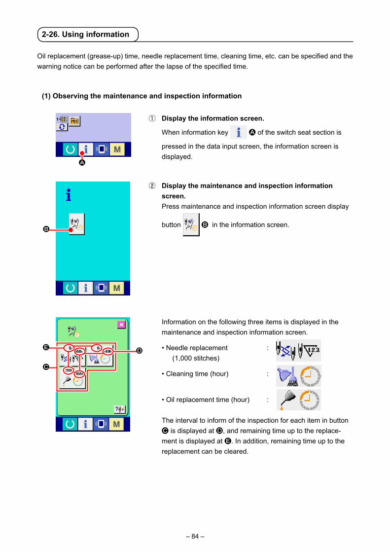
– 84 –
2-26. Using information
Oil replacement (grease-up) time, needle replacement time, cleaning time, etc. can be specified and the warning notice can be performed after the lapse of the specified time.
(1) Observing the maintenance and inspection information
① Display the information screen.
When information key A of the switch seat section is
pressed in the data input screen, the information screen is displayed.
② Display the maintenance and inspection information screen.
Press maintenance and inspection information screen display
button B in the information screen.
A
B
DE
C
Information on the following three items is displayed in the maintenance and inspection information screen.
• Needle replacement : (1,000 stitches)
• Cleaning time (hour) :
• Oil replacement time (hour) :
The interval to inform of the inspection for each item in button C is displayed at D, and remaining time up to the replace-ment is displayed at E. In addition, remaining time up to the replacement can be cleared.

– 85 –
(2) Releasing procedure of the warning
When the designated inspection time is reached, the warning screen is displayed.
In case of clearing the inspection time, press CLEAR button
A. The inspection time is cleared and the pop-up is closed. In case
of not clearing the inspection time, press CANCEL button B
and close the pop-up. Every time one sewing is completed, the warning screen is displayed until the inspection time is cleared.Warning Nos. of the respective items are as follows. • Needle replacement : A201 • Cleaning time : A202 • Oil replacement time : A203
For the grease-up portion, refer to the item of "III-1-12. Replenishing the designated places with grease" p.123 .
③ Perform clearing remaining time up to the replacement. When button C of the item you desire to clear is pressed, the
time of replacement clear screen is displayed. When CLEAR
button F is pressed, the remaining time up to the re-
placement is cleared.
④ Display the threading diagram.
When threading button G displayed in the maintenance
and inspection screen is pressed, the needle thread threading diagram is displayed.
Observe it when performing threading.
F
G
B
A

– 86 –
Data can be sent/received to/from a personal computer or the like, by means of a USB cable.
(3) Performing communication by using USB
If the contact part becomes dirty, failure of contact will be caused. Do not touch by hand, and control so that dust, oil or other foreign material does not adhere to it. In addition, the inside element is damaged by static electrici-ty or the like. So, be very careful when handling.
(2) Performing communication by using the media
For handling way of the media, read "II-1. PREFACE" p.27 .
Communication function can download the sewing data created with other sewing machine, creation of sewing data and sewing data created by editing device PM-1 to the sewing machine. In addition, the function can upload the aforementioned data to the media or personal computer.As the means of communication, a media slot and USB port are prepared.
* However, SU-1 (data server utility) is necessary to perform download/upload from the personal computer.
(1) Handling possible data
Sewing data that can be handled are 4 kinds below, and the respective data formats are as shown be-low.
xxx: file No.
* For the simplified program, see the Engineer's Manual.
2-27. Using communication function
Data name Extension Description of data
Vector format data VD00XXX.VDTIt is the data of needle entry point created with PM-1, and the data format that can be operated in common between JUKI sewing machines.
M3 data AMS0XXX.M3 Pattern data for the AMS-B, -C and -D Series
Sewing standard format data
SD00XXX.DAT Data of sewing standard format
Simplified program data AMS0XXX.PRO Simplified program data
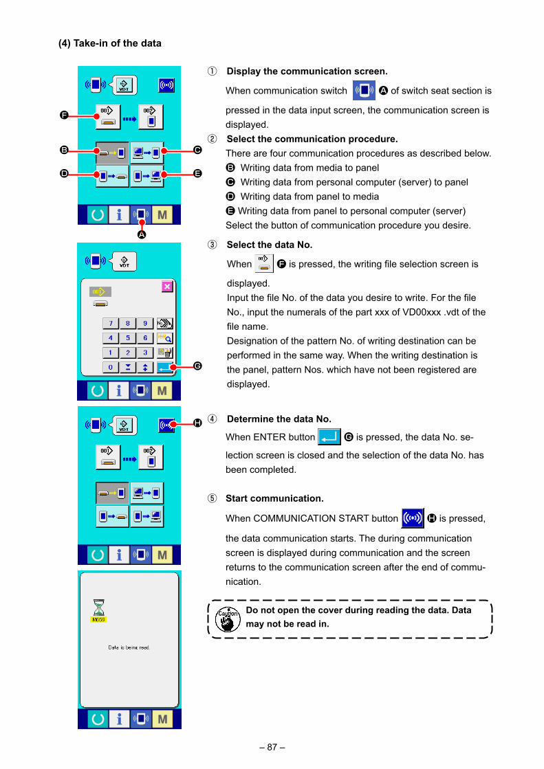
– 87 –
④ Determine the data No.
When ENTER button G is pressed, the data No. se-
lection screen is closed and the selection of the data No. has been completed.
⑤ Start communication.
When COMMUNICATION START button H is pressed,
the data communication starts. The during communication screen is displayed during communication and the screen returns to the communication screen after the end of commu-nication.
Do not open the cover during reading the data. Data may not be read in.
① Display the communication screen.
When communication switch A of switch seat section is
pressed in the data input screen, the communication screen is displayed.
② Select the communication procedure. There are four communication procedures as described below. B Writing data from media to panel C Writing data from personal computer (server) to panel D Writing data from panel to media E Writing data from panel to personal computer (server) Select the button of communication procedure you desire.
③ Select the data No.
When F is pressed, the writing file selection screen is
displayed. Input the file No. of the data you desire to write. For the file
No., input the numerals of the part xxx of VD00xxx .vdt of the file name.
Designation of the pattern No. of writing destination can be performed in the same way. When the writing destination is the panel, pattern Nos. which have not been registered are displayed.
(4) Take-in of the data
B
D
C
F
A
E
G
H

– 88 –
(5) Taking in plural data together
It is possible for vector data, M3 data and sewing standard format data to select plural writing data and write them together. Pattern No. of writing destination will become the same No. of the selected data No.
① Display the writing file selection screen.
When PLURAL SELECTION button A is pressed, the
data No. plural selection screen is displayed.
② Perform the data No. selection. Since the list of existing data file numbers is displayed, press
FILE NO. button B you desire to write. It is possible to invert
the selected state of the button with INVERSION button
C.
③ Determine the data No.
When ENTER button D is pressed, the data No. plural
selection screen is closed and the data selection ends.
④ Start the communication.
When COMMUNICATION START button E is pressed,
the data communication starts.
A
C
B
D
E

– 89 –
Data No. during communication, total number of writing data and number of data that have ended the data communication are dis-played in the during communication screen.
* When performing writing to the pattern No. which already exists, the overwriting confirmation screen is displayed before writing. When performing overwriting, press ENTER button
F.
When performing overwriting all without displaying the over-writing confirmation screen, press OVERWRITING button
G in all cases.
F
G

– 90 –
① Display the media format screen.
When switch is held pressed for three seconds, MEDIA
FORMAT button A is displayed on the screen. When
this button is pressed, the media format screen is displayed.
2-28. Performing formatting of the media
To re-format a medium, the IP-420 has to be used. The IP-420 is not able to read any medium which is formatted on a personal computer.
② Start formatting of the media. Set the media you desire to format to the media slot, close
the cover, press ENTER button B and formatting starts.
Save necessary data in the media to the other media before formatting. When formatting is performed, the inside data are deleted.
B
A
When two or more media are connected to the sewing machine, the medium to be formatted is determined by the predetermined priority order. High → LowCF(TM) slot → USB device 1 → USB device 2 → ....When a CompactFlash (TM) is inserted in the CF(TM) slot, the CompactFlash (TM) will be formatted accord-ing to the priority order as shown above.Refer to the USB specifications for the priority order of access.

– 91 –
2-29. USING 2-STEP STROKE FUNCTION
2-step stroke function can be used by changing setting of memory switches and .
① Display the memory switch data list screen. Display the memory switch data list screen. Refer to "II-2-25. Changing memory switch data" p.83 for
how to display the memory switch data list screen.② Change the memory switch data. (Make the 2-step stroke
function effective.) Select from the memory switch list screen and set as
below. AMS-210EN-SS/HS-1306 : 0 to 1 AMS-210EN-SL/HL-1306 (Right/left separated pressers) : 1 to 10 Other (Solid presser) : 8 to 9 In case of the right/left separated pressers, it is possible to
perform the memory switch setting to limit the lowering order of right/left pressers.
For the contents of memory switch setting, see "II-3. MEMORY SWITCH DATA LIST" p.97 .
When using the 2-step stroke function, you can stop the presser at the intermediate position you desire. * For the pneumatic type of AMS-210EN-1306, the presser, left only is of 2-step stroke.
(1) Setting of 2-step stroke function
(2) Setting of 2-step stroke positionIn the setting of 2-step stroke position, perform the adjustment of intermediate position to stop the presser. As the setting value is increased, the presser stops at the lower position.
For the pneumatic type presser, the presser gradually comes down with the lapse of time after stopping at the 2-step stroke position. In this case, repeat the operation since the presser goes up when the pedal is depressed again.
[ When setting 2-step stroke position of user's pattern ]
2-step stroke position used in the user's pattern can be set with memory switch .① Display the memory switch data list screen. Display the memory switch data list screen. Refer to "II-2-25. Changing memory switch data" p.83 for
how to display the memory switch data list screen.② Change the memory switch data. Select from the memory switch list screen and set
2-step stroke position. Input possible range of 2-step stroke position depends on the
presser types.
Presser used Input range Initial valueMotor type 50 to 90 70Pneumatic type 10 to 300 (msec) 35

– 92 –
[ When setting 2-step stroke position of pattern button ]
In case of the pattern button, 2-step stroke position can be set to each pattern button data.
① Display the data input screen at the time of pattern button selection.
Only in case of data input screen (blue) at the time of pattern selection, the contents of pattern can be changed. Incase of
sewing screen (green), press READY key to display the
data input screen at the time of pattern button selection.
② Display the pattern data change screen.
Press PATTERN BUTTON DATA CHANGE button A
and the pattern button data change screen is displayed.
③ Display 2-step stroke position setting screen.
Press 2-STEP STROKE POSITION CHANGE button
B and the 2-step stroke position setting screen is displayed. Input possible range of 2-step stroke position depends on the
presser types.
A
B

– 93 –
(3) Motion of 2-step stroke function
By setting memory switch or , Motion of pedal or presser can be selected.
1. In case of pneumatic type presser, the height of intermediate position changes by ad-justing the air pressure and speed controller of the sewing machine.
2. Start of sewing with left pedal becomes effective when 0.3 seconds pass after the press-er moved to the lowest position.
① When depressing 1st step of the intermediate pedal, the presser stops at the intermediate position.
② When further depressing 2nd step in the state that 1st step of the intermediate pedal is depressed, the presser comes down to the bottom position.
③ When the left lever is pressed with the presser at the bottom, sewing starts.
④ When depressing 1st step of the intermediate pedal again in the state that the presser is in the intermediate position, the presser goes up to the top.
⑤ When depressing the interme-diate pedal again in the state that the presser is in the bottom position, the presser goes up to the top.
[ When solid presser 2-step stroke is selected (PK-47 is used. ]
When is set to 9 (solid presser 2-step stroke) with the right/left separated press-ers installed, the right/left pressers are driven up and down at the same time and the same control as that of the solid presser can be also performed.
➡
➡➡
➡
➡
➡➡
▷▷
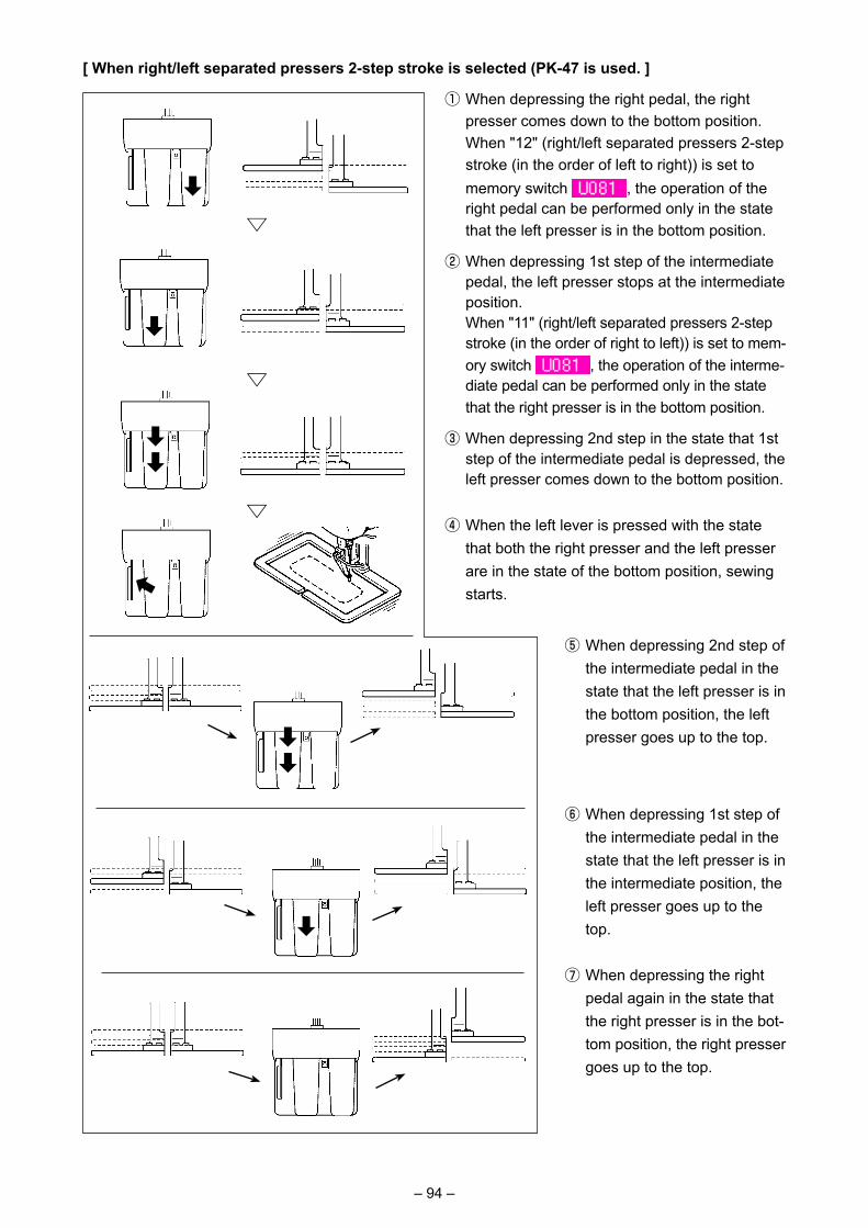
– 94 –
[ When right/left separated pressers 2-step stroke is selected (PK-47 is used. ]
① When depressing the right pedal, the right presser comes down to the bottom position.
When "12" (right/left separated pressers 2-step stroke (in the order of left to right)) is set to memory switch , the operation of the right pedal can be performed only in the state that the left presser is in the bottom position.
② When depressing 1st step of the intermediate pedal, the left presser stops at the intermediate position.
When "11" (right/left separated pressers 2-step stroke (in the order of right to left)) is set to mem-ory switch , the operation of the interme-diate pedal can be performed only in the state that the right presser is in the bottom position.
③ When depressing 2nd step in the state that 1st step of the intermediate pedal is depressed, the left presser comes down to the bottom position.
④ When the left lever is pressed with the state that both the right presser and the left presser are in the state of the bottom position, sewing starts.
⑤ When depressing 2nd step of the intermediate pedal in the state that the left presser is in the bottom position, the left presser goes up to the top.
⑥ When depressing 1st step of the intermediate pedal in the state that the left presser is in the intermediate position, the left presser goes up to the top.
⑦ When depressing the right pedal again in the state that the right presser is in the bot-tom position, the right presser goes up to the top.
➡
▷▷
▷
➡
➡➡
➡
➡
➡➡

– 95 –
A
2-30. Operation at the time of X/Y motor position slip
When X/Y motor detects the position slip, the error screen is displayed.Timing of error display can be changed with the selection of memory switch. For the details, refer to the Engineer's Manual.
(1) When the error is displayed during sewing
① Release the error.
Press RESET button A to release the error and the
thread trimming pop-up is displayed.
② Perform thread trimming. When it seems to be no problem after checking the stitches,
depress the start pedal without change and re-start the sew-ing.
If not, press THREAD TRIM button B and perform
thread trimming. When performing thread trimming, the feed forward/back pop-
up is displayed.
③ Adjust the presser to the re-sewing position.
Every time FEED BACK button C is pressed, the press-
er returns by one stitch. Every time FEED FORWARD button
D is pressed, the presser moves forward by one stitch.
Move the presser up to the re-sewing position.
In addition, when RETURN TO ORIGIN button E is
pressed, the pop-up is closed, the sewing screen is displayed, and the presser returns to the sewing start position.
④ Re-start sewing. When the pedal is depressed, sewing starts again.
B
EDC
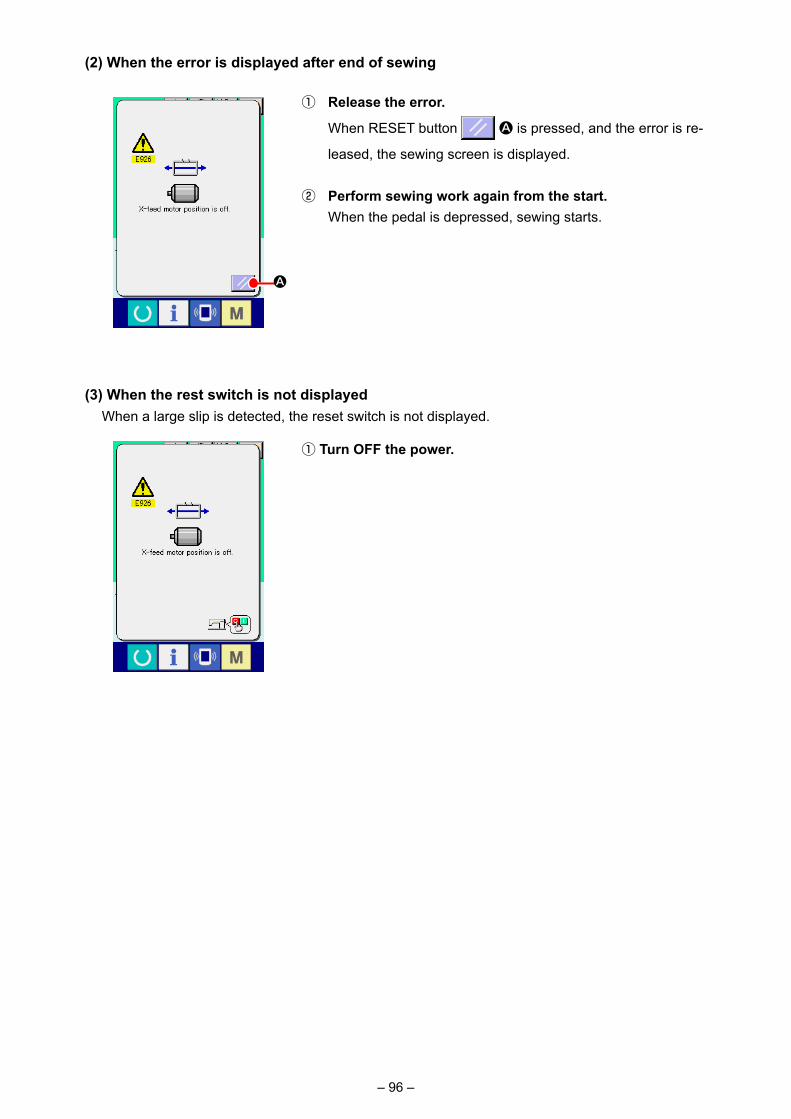
– 96 –
A
(2) When the error is displayed after end of sewing
① Release the error.
When RESET button A is pressed, and the error is re-
leased, the sewing screen is displayed.
② Perform sewing work again from the start. When the pedal is depressed, sewing starts.
(3) When the rest switch is not displayed When a large slip is detected, the reset switch is not displayed.
① Turn OFF the power.
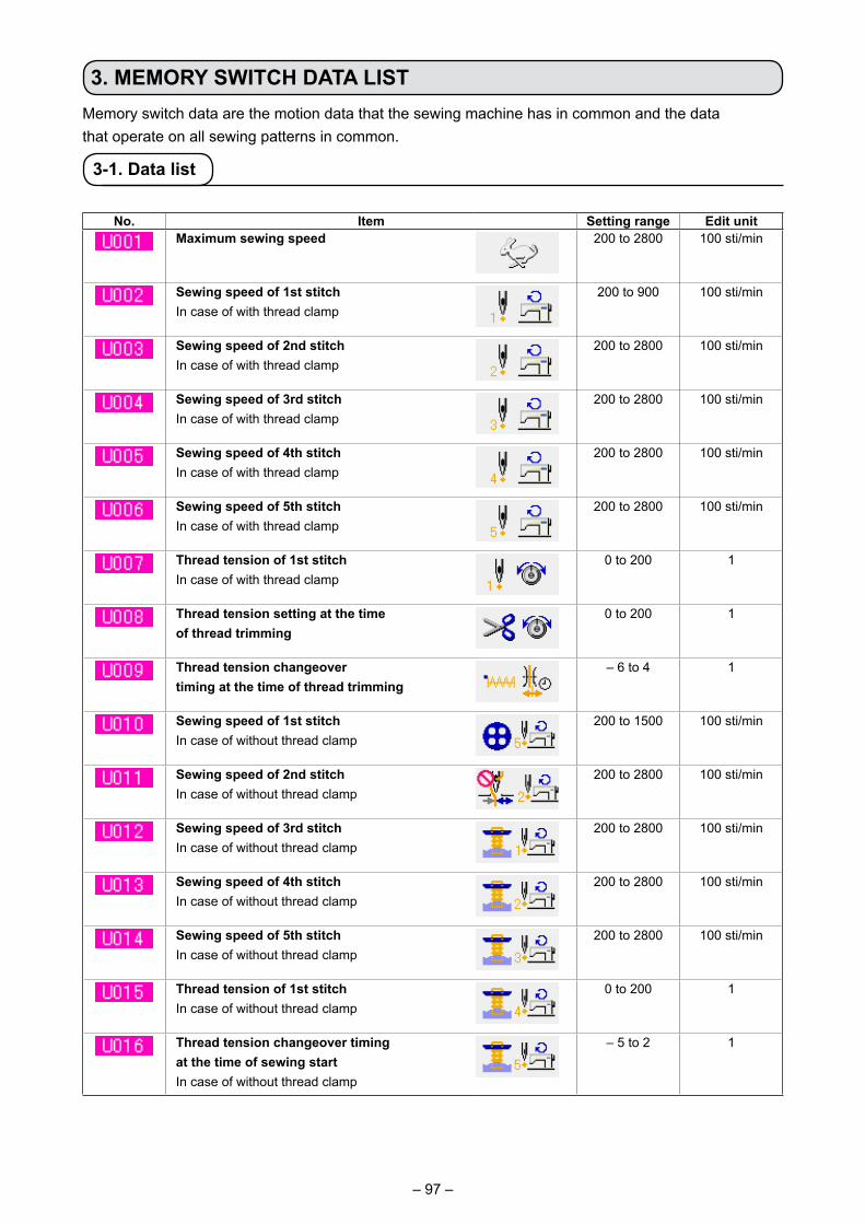
– 97 –
3. MEMORY SWITCH DATA LISTMemory switch data are the motion data that the sewing machine has in common and the datathat operate on all sewing patterns in common.
3-1. Data list
No. Item Setting range Edit unitMaximum sewing speed 200 to 2800 100 sti/min
Sewing speed of 1st stitchIn case of with thread clamp
200 to 900 100 sti/min
Sewing speed of 2nd stitchIn case of with thread clamp
200 to 2800 100 sti/min
Sewing speed of 3rd stitchIn case of with thread clamp
200 to 2800 100 sti/min
Sewing speed of 4th stitchIn case of with thread clamp
200 to 2800 100 sti/min
Sewing speed of 5th stitchIn case of with thread clamp
200 to 2800 100 sti/min
Thread tension of 1st stitchIn case of with thread clamp
0 to 200 1
Thread tension setting at the time of thread trimming
0 to 200 1
Thread tension changeovertiming at the time of thread trimming
– 6 to 4 1
Sewing speed of 1st stitch In case of without thread clamp
200 to 1500 100 sti/min
Sewing speed of 2nd stitchIn case of without thread clamp
200 to 2800 100 sti/min
Sewing speed of 3rd stitchIn case of without thread clamp
200 to 2800 100 sti/min
Sewing speed of 4th stitchIn case of without thread clamp
200 to 2800 100 sti/min
Sewing speed of 5th stitchIn case of without thread clamp
200 to 2800 100 sti/min
Thread tension of 1st stitchIn case of without thread clamp
0 to 200 1
Thread tension changeover timing at the time of sewing startIn case of without thread clamp
– 5 to 2 1

– 98 –
No. Item Setting range Edit unitCounter motion selection --- ---
Sewing counter No. of pcs. counter Bobbin counterHeight of eight of presser at the time of 2 step stroke
(Control by motor)50 to 90
(Control by air)10 to 300
1
Buzzer sound can be prohibited. --- ---
Without buzzer sound
Panel operating sound Panel operating sound + errorNumber of stitches of thread clamp release is set.
1 to 7 1
Clamping timing of thread clamp can be delayed.
- 10 to 0 1
Thread clamp control can be prohibited. --- ---
Normal ProhibitedFeed motion timing is selected.Set the timing in “–” direction when stitch is not well-tightened.
- 8 to 16 1
State of the presser after end of sewing is selected. --- ---
Presser goes up after moving at start
of sewing.
Presser goes up immediately after end of sewing.
Presser goes up by pedal operation
after moving at start of sewing.
The presser foot moves to the sewing starting point, then goes up with the presser foot lifting switch.
The sewing machine starts sewing with the start switch. When the sewing machine stops midway through sewing, the presser foot goes
up at the preset presser lift position.Presser lifting motion at the end of sewing can be set. --- ---
With presser up Without presser upOrigin retrieval can be performed every time after end of sewing (other than combination sewing)
--- ---
Without origin retrieval With origin retrievalOrigin retrieval in combination sewing can be set. --- ---
Without origin retrieval
Every time 1 pattern is finished.
Every time 1 cycle is finished.

– 99 –
No. Item Setting range Edit unitState of presser when sewing machine stops by temporary stop command can be selected.
--- ---
Presser rise. Presser rise with presser switch.
Needle stop position is set. --- ---
UP position Upper dead pointThread trimming can be prohibited. --- ---
Normal Thread trimming prohibited
Route of return to origin by return to origin button can be selected. --- ---
Linear return Reverse return of pattern
Origin retrieval → Sewing start point
Bobbin winding speed can be set. 800 to 2000 100 sti/min
Motion method of wiper can be selected. --- ---
Invalid Magnet typewiper
Unit of sewing shape size change can be selected. --- ---
%input Actual size inputThread tension output time when setting thread tension can be set.
0 to 20 1
Bend position of thread clamp is selected.0 : S type1 : H type thin thread (#50 to #8)2 : H type intermediate3 : H type thick thread (#5 to #2)
--- ---
Thread clamp and thread clamp position selection --- ---
Front position Rear positionThread breakage detection selection --- ---
Thread breakage detection invalid
Thread breakage detection valid
Number of invalid stitches at the start of sewing of thread breakage detection
0 to 15 stitches
1 stitch
Number of invalid stitches during sewing of thread breakage detection
0 to 15 stitches
1 stitch

– 100 –
No. Item Setting range Edit unitFeeding frame control : pedal open/closeOperation order of feeding frame by pedaloperation at the normal time is set.
0 to 99 1
(At the time of control by motor)0 : Solid presser1 : Solid presser 2-step stroke (Lowering again with presser switch)2 : Solid presser 2-step stroke (Down to the bottom + start with start switch)3 : Solid presser 2-step stroke (Intermediate → down to bottom → going up with presser switch)4 to 99 : Solid presser (At the time of control by air)0 : Solid presser1 : Right/left separated presser (Without priority of right/left)2 : Right/left separated presser (In the order of right to left)3 : Right/left separated presser (In the order of left to right)4 to 7 : Special type (*1)8 : Solid presser9 : Solid presser 2-step stroke10 : Right/left separated presser 2-step stroke (Without right/left separation)11 : Right/left separated presser 2-step stroke (Order of right to left)12 : Right/left separated presser 2-step stroke (Order of left to right)13 to 99 : Solid presser*1 : When using these items, refer to Engineer's Manual.Feeding frame control : midway stop time open/closeOperation order of feeding frame by pedal operation when lifting the feeding frame by the temporary stop command in the pattern data is set.
0 to 99 1
(At the time of control by motor)0 : Solid presser1 : Solid presser 2-step stroke (Down to bottom with presser switch)2 : Solid presser 2-step stroke (Down to the bottom + start with start switch)3 : Solid presser 2-step stroke (Intermediate → down to bottom → going up with presser switch)4 to 99 : Solid presser(At the time of control by air)0 : Solid presser1 : Right/left separated presser (Without priority of right/left)2 : Right/left separated presser (In the order of right to left)3 : Right/left separated presser (In the order of left to right)4 to 7 : Special type (*1)8 : Solid presser9 : Solid presser 2-step stroke10 : Right/left separated presser 2-step stroke (Without right/left separation)11 : Right/left separated presser 2-step stroke (Order of right to left)12 : Right/left separated presser 2-step stroke (Order of left to right)13 to 99 : Solid presser*1 : When using these items, refer to Engineer's Manual.

– 101 –
No. Item Setting range Edit unitPedal switch 1 with/without latch --- ---
Without WithPedal switch 2 with/without latch --- ---
Without WithPedal switch 3 with/without latch --- ---
Without WithPedal switch 4 with/without latch --- ---
Without WithEnlarging/reducing function mode --- ---
Prohibited Increasing/decreasing number of stitches
(Pitch is fixed.)
Increasing/decreasing pitch (Number of stitches is fixed.)
Jog move function mode --- ---
Prohibited Parallel move 2nd origin specified later
Retainer compensation motion : selection of motion --- ---
Without motion With motionSelection of needle upper dead point at the time of origin retrieval/return to origin
--- ---
Without WithTemporary stop : thread trimming operation --- ---
Automatic thread trimming
Manual (Thread trimming by turning
Stop switch ON again)Main motor X/Y feed synchronized control : speed/pitch --- ---
2800 sti/min/ 4. 0mm
2200 sti/min/ 4. 0mm
1800 sti/min/ 4. 0mm
1400 sti/min/ 4. 0mm

– 102 –
No. Item Setting range Edit unitIntermediate presser with/without control --- ---
Without (Lowering fixed)
With (Lowering with sewing data at the time
of operation)
With (Lowering even a t the t ime o f feed
forward/backward)Intermediate presser lowering timing --- ---
Immediately before start-up of machine head
Synchronized with the last feeding frame
Intermediate presser : wiper sweeping position --- ---
Sweeping above intermediate presser
Sweeping above inter-mediate presser (posi-tion where intermediate presser lowers most)
Sweeping below intermediate
presser
With/without air pressure detection --- ---
Without WithIntermediate presser DOWN position setting→ Refer to "I-4-8. Intermediate presser height" p.23 .
0 to 7.0mm 0.1
With/without needle cooler control --- ---
Without WithThe time to automatically exit from the count-up screen can be set.
0〜 99 1
Selection of needle upper dead point at the time of originretrieval/return to origin
--- ---
Without WithGrease-up errorClearing of number of stitches of grease-up is performed.→ Refer to "III-1-12. Replenishing the designated places with grease" p.123 .
--- ---
Language selection
Japanese English Chinese (traditional)
Chinese (simplified)
Spanish Italian French German
Portuguese Turkish Vietnamese Korean
Indonesian Russian
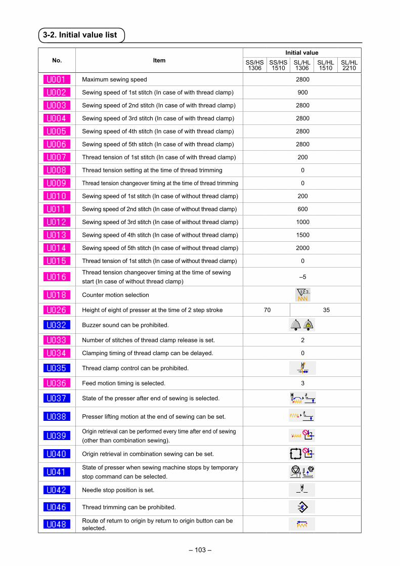
– 103 –
3-2. Initial value list
No. ItemInitial value
SS/HS 1306
SS/HS 1510
SL/HL 1306
SL/HL 1510
SL/HL 2210
Maximum sewing speed 2800
Sewing speed of 1st stitch (In case of with thread clamp) 900
Sewing speed of 2nd stitch (In case of with thread clamp) 2800
Sewing speed of 3rd stitch (In case of with thread clamp) 2800
Sewing speed of 4th stitch (In case of with thread clamp) 2800
Sewing speed of 5th stitch (In case of with thread clamp) 2800
Thread tension of 1st stitch (In case of with thread clamp) 200
Thread tension setting at the time of thread trimming 0
Thread tension changeover timing at the time of thread trimming 0
Sewing speed of 1st stitch (In case of without thread clamp) 200
Sewing speed of 2nd stitch (In case of without thread clamp) 600
Sewing speed of 3rd stitch (In case of without thread clamp) 1000
Sewing speed of 4th stitch (In case of without thread clamp) 1500
Sewing speed of 5th stitch (In case of without thread clamp) 2000
Thread tension of 1st stitch (In case of without thread clamp) 0
Thread tension changeover timing at the time of sewing start (In case of without thread clamp)
–5
Counter motion selection
Height of eight of presser at the time of 2 step stroke 70 35
Buzzer sound can be prohibited.
Number of stitches of thread clamp release is set. 2
Clamping timing of thread clamp can be delayed. 0
Thread clamp control can be prohibited.
Feed motion timing is selected. 3
State of the presser after end of sewing is selected.
Presser lifting motion at the end of sewing can be set.
Origin retrieval can be performed every time after end of sewing (other than combination sewing).
Origin retrieval in combination sewing can be set.
State of presser when sewing machine stops by temporary stop command can be selected.
Needle stop position is set.
Thread trimming can be prohibited.
Route of return to origin by return to origin button can be selected.

– 104 –
No. ItemInitial value
SS/HS 1306
SS/HS 1510
SL/HL 1306
SL/HL 1510
SL/HL 2210
Bobbin winding speed can be set. 1600
Motion method of wiper can be selected.
Unit of sewing shape size change can be selected.
Thread tension output time when setting thread tension can be set. 20
Bend position of thread clamp is selected. S type : 0 / H type : 1
Thread clamp and thread clamp position selection
Thread breakage detection selection
Number of invalid stitches at the start of sewing of thread breakage detection 8
Number of invalid stitches during sewing of thread breakage detection 3
Feeding frame control : pedal open/close 0 1 8
Feeding frame control : midway stop time open/close 0 1 8
Pedal switch 1 with/without latch
Pedal switch 2 with/without latch
Pedal switch 3 with/without latch
Pedal switch 4 with/without latch
Enlarging/reducing function mode
Jog move function mode
Retainer compensation motion : selection of motion
Selection of needle upper dead point at the time of origin retrieval/return to origin
Temporary stop : thread trimming operation
Main motor X/Y feed synchronized control : speed/pitch
Intermediate presser with/without control
Intermediate presser lowering timing
Intermediate presser : wiper sweeping position
With/without air pressure detection
Intermediate presser DOWN position setting 3.5
With/without needle cooler control
The time to automatically exit from the count-up screen can be set. 0
Enable/disable of shape display at the time of pattern selection
Grease-up error -
Language selection Not set

– 105 –
4. ERROR CODE LIST
Error code Display Description of error Display message How to recover Place of recovery
E007 Machine lockMain shaft of the sewing machine fails to rotate due to some trouble.
Turn OFF the power
E008 Head connector abnormalityMemory of machine head cannot be read.
Turn OFF the power
E010 Pattern No. errorPattern No. which is backed up is not registered to data ROM, or setting of reading inoperative is performed.
Possible to re-enter after reset.
Previous screen
E011 External media not insertedExternal media is not inserted.
Possible to re-enter after reset.
Previous screen
E012 Read errorData read from external media cannot be performed.
Possible to re-start after reset.
Previous screen
E013 Write errorData write from external media cannot be performed.
Possible to re-start after reset.
Previous screen
E015 Format errorFormat cannot be performed.
Possible to re-start after reset.
Previous screen
E016 External media capacity overCapacity of external media is short.
Possible to re-start after reset.
Previous screen
E017 Machine memory capacity overMachine memory capacity is insufficient.
Possible to re-start after reset.
Previous screen
E019 File size overFile is too large.
Possible to re-start after reset.
Previous screen

– 106 –
Error code Display Description of error Display message How to recover Place of recovery
E024 Pattern data size overMemory size is over.
Possible to re-start after reset.
Data inputscreen
E027 Read errorData read from server cannot be performed.
Possible to re-start after reset.
Previous screen
E028 Write errorData write from server cannot be performed.
Possible to re-start after reset.
Previous screen
E029 Media slot release errorLid of media slot is open.
Possible to re-start after reset.
Previous screen
E030 Needle bar position missing errorNeedle bar is not in the predetermined position.
Turn hand pulley to bring needle bar to its predetermined position.
Data inputscreen
E031 Air pressure dropAir pressure is dropped.
Possible to re-start after reset.
Data inputscreen
E032 File interchanging errorFile cannot be read.
Possible to re-start after reset.
Data inputscreen
E040 Sewing area over Possible to re-start after reset.
Sewing screen
E043 Enlarging errorSewing pitch exceeds Max. pitch.
Possible to re-start after reset.
Data inputscreen
E045 Pattern data error Possible to re-start after reset.
Data inputscreen
E050 Stop switchWhen stop switch is pressed during machine running.
Possible to re-start after reset.
Step screen
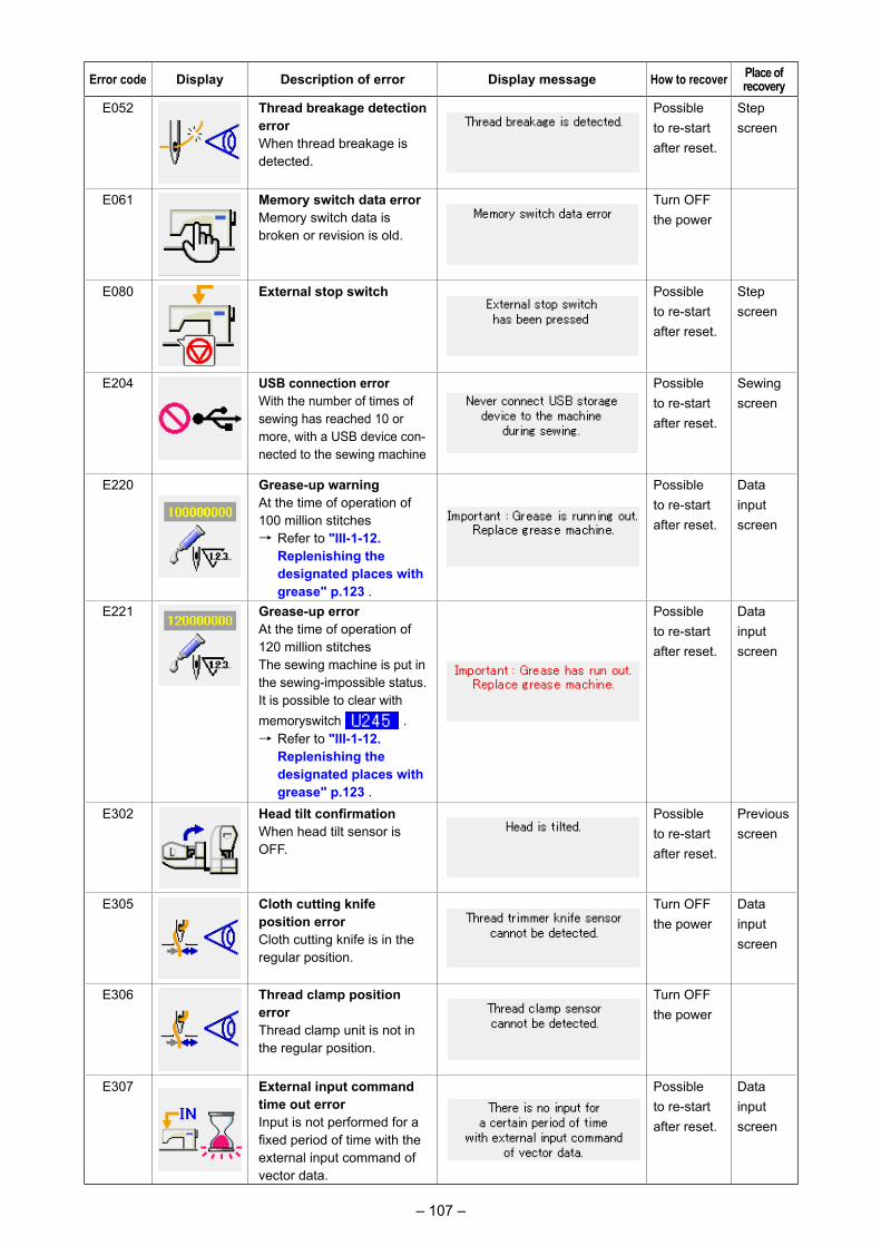
– 107 –
Error code Display Description of error Display message How to recover Place of recovery
E052 Thread breakage detection errorWhen thread breakage is detected.
Possible to re-start after reset.
Step screen
E061 Memory switch data errorMemory switch data is broken or revision is old.
Turn OFF the power
E080 External stop switch Possible to re-start after reset.
Step screen
E204 USB connection errorWith the number of times of sewing has reached 10 or more, with a USB device con-nected to the sewing machine
Possible to re-start after reset.
Sewing screen
E220 Grease-up warningAt the time of operation of 100 million stitches→ Refer to "III-1-12.
Replenishing the designated places with grease" p.123 .
Possible to re-start after reset.
Data inputscreen
E221 Grease-up errorAt the time of operation of 120 million stitchesThe sewing machine is put in the sewing-impossible status. It is possible to clear with memoryswitch .→ Refer to "III-1-12.
Replenishing the designated places with grease" p.123 .
Possible to re-start after reset.
Data inputscreen
E302 Head tilt confirmationWhen head tilt sensor is OFF.
Possible to re-start after reset.
Previous screen
E305 Cloth cutting knife position errorCloth cutting knife is in the regular position.
Turn OFF the power
Data inputscreen
E306 Thread clamp position errorThread clamp unit is not in the regular position.
Turn OFF the power
E307 External input command time out errorInput is not performed for a fixed period of time with the external input command of vector data.
Possible to re-start after reset.
Data inputscreen

– 108 –
Error code Display Description of error Display message How to recover Place of recovery
E308 Time-out error of wait terminalThere is no input to wait terminal for a certain period of time.
Turn OFF the power
E406 Password mismatch error Possible to re-start after reset.
Pass-word input screen
E703 Panel is connected to the sewing machine which is not supposed. (Machine type error)When the machine type code of system is not proper in the initial communication.
Possible to rewrite pro-gram after p r e s s i n g down com-munication switch.
Commu-ni-cation screen
E704 Inconsistency of system versionSystem software version is inconsistent in the initial communication.
Possible to rewrite pro-gram after p r e s s i n g down com-munication switch.
Commu-ni-cation screen
E730 Main shaft motor encoder defectivenessWhen encoder of the sewing machine motor is abnormal.
Turn OFF the power
E731 Main motor hole sensor is defective or position sensor is defective.Hole sensor or position sensor of the sewing machine motor is defective.
Turn OFF the power
E733 Reverse rotation of main shaft motorWhen sewing machine motor rotates in reverse direction.
Turn OFF the power
E802 Power electrical discontinuity detection
Turn OFF the power
E811 OvervoltageWhen input power is more than the specified value.
Turn OFF the power
E813 Low voltageWhen input power is less than the specified value.
Turn OFF the power

– 109 –
Error code Display Description of error Display message How to recover Place of recovery
E901 Main shaft motor IPM abnormalityWhen IPM of servo control p.c.b. is abnormal.
Turn OFF the power
E903 Stepping motor power abnormalityWhen stepping motor power of SERVO CONTROL p. c. b. fluctuates more than ± 15%.
Turn OFF the power
E904 Solenoid power abnormalityWhen solenoid power of SERVO CONTROL p. c. b.fluctuates more than ± 15%.
Turn OFF the power
E905 Heat sink temperature for SERVO CONTROL p. c. b. abnormalityTurn ON the power again after taking overheat time of SERVO CONTROL p. c. b.
Turn OFF the power
E907 X feed motor origin retrieval errorWhen origin sensor signal is not inputted at the time of origin retrieval motion.
Turn OFF the power
E908 Y feed motor origin retrieval errorWhen origin sensor signal is not inputted at the time of origin retrieval motion.
Turn OFF the power
E910 Presser motor origin retrieval errorWhen origin sensor signal is not inputted at the time of origin retrieval motion.
Turn OFF the power
E913 Thread clamp origin retrieval errorWhen origin sensor signal is not inputted at the time of origin retrieval motion.
Turn OFF the power
E914 Feed defective errorTiming lag between feed and main shaft occurs.
Turn OFF the power
E915 Communication abnormality between operation panel and MAIN CPUWhen abnormality occurs in data communication.
Turn OFF the power
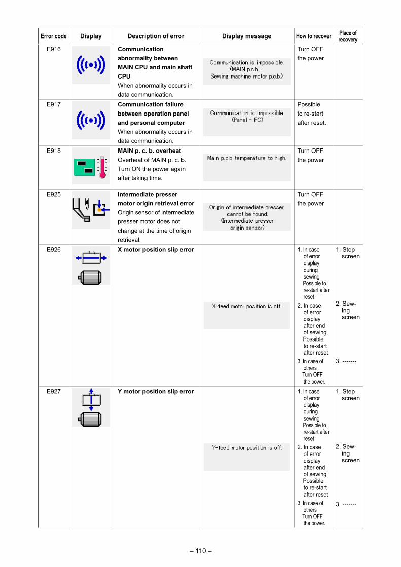
– 110 –
Error code Display Description of error Display message How to recover Place of recovery
E916 Communication abnormality between MAIN CPU and main shaft CPUWhen abnormality occurs in data communication.
Turn OFF the power
E917 Communication failure between operation panel and personal computerWhen abnormality occurs in data communication.
Possible to re-start after reset.
E918 MAIN p. c. b. overheat Overheat of MAIN p. c. b.Turn ON the power again after taking time.
Turn OFF the power
E925 Intermediate presser motor origin retrieval errorOrigin sensor of intermediate presser motor does not change at the time of origin retrieval.
Turn OFF the power
E926 X motor position slip error 1. In case of error display during sewing
Possible to re-start after reset
2. In case of error display after end of sewing
Possible to re-start after reset
3. In case of others
Turn OFF the power.
1. Step screen
2. Sew-ing screen
3. -------
E927 Y motor position slip error 1. In case of error display during sewing
Possible to re-start after reset
2. In case of error display after end of sewing
Possible to re-start after reset
3. In case of others
Turn OFF the power.
1. Step screen
2. Sew-ing screen
3. -------
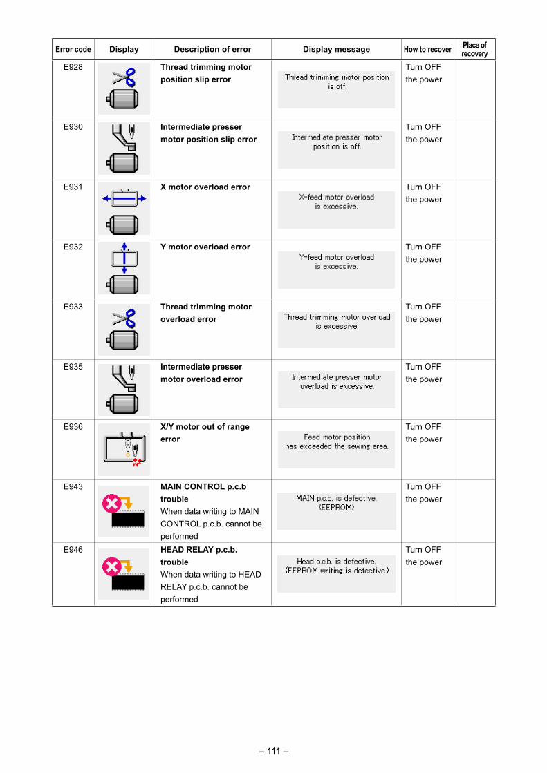
– 111 –
Error code Display Description of error Display message How to recover Place of recovery
E928 Thread trimming motor position slip error
Turn OFF the power
E930 Intermediate presser motor position slip error
Turn OFF the power
E931 X motor overload error Turn OFF the power
E932 Y motor overload error Turn OFF the power
E933 Thread trimming motor overload error
Turn OFF the power
E935 Intermediate presser motor overload error
Turn OFF the power
E936 X/Y motor out of range error
Turn OFF the power
E943 MAIN CONTROL p.c.b troubleWhen data writing to MAIN CONTROL p.c.b. cannot be performed
Turn OFF the power
E946 HEAD RELAY p.c.b. troubleWhen data writing to HEAD RELAY p.c.b. cannot be performed
Turn OFF the power

– 112 –
Message No. Display Display message DescriptionM520 Erase confirmation of Users'
pattern Erase is performed. OK ?
M521 Erase confirmation of pattern button Erase is performed. OK ?
M522 Erase confirmation cycle patternErase is performed. OK ?
M523 Erase confirmation of backup data Pattern data is not stored in memory. Erase is OK ?
M528 Overwriting confirmation of users' pattern Overwriting is performed. OK ?
M529 Overwriting confirmation of mediaOverwriting is performed. OK ?
M530 Overwriting confirmation of vector data of panel/M3 data/sewing standard format data/simplified program data Overwriting is performed. OK ?
M531 Overwriting confirmation of vector data of media/M3 data/sewing standard format data/simplified program dataOverwriting is performed. OK ?
M532 Overwriting confirmation of vector data on personal computer/M3 data/sewing standard format data/simplified program dataOverwriting is performed. OK ?
M534 Overwriting confirmation of adjustment data of media and all machine dataOverwriting is performed. OK ?
5. MESSAGE LIST
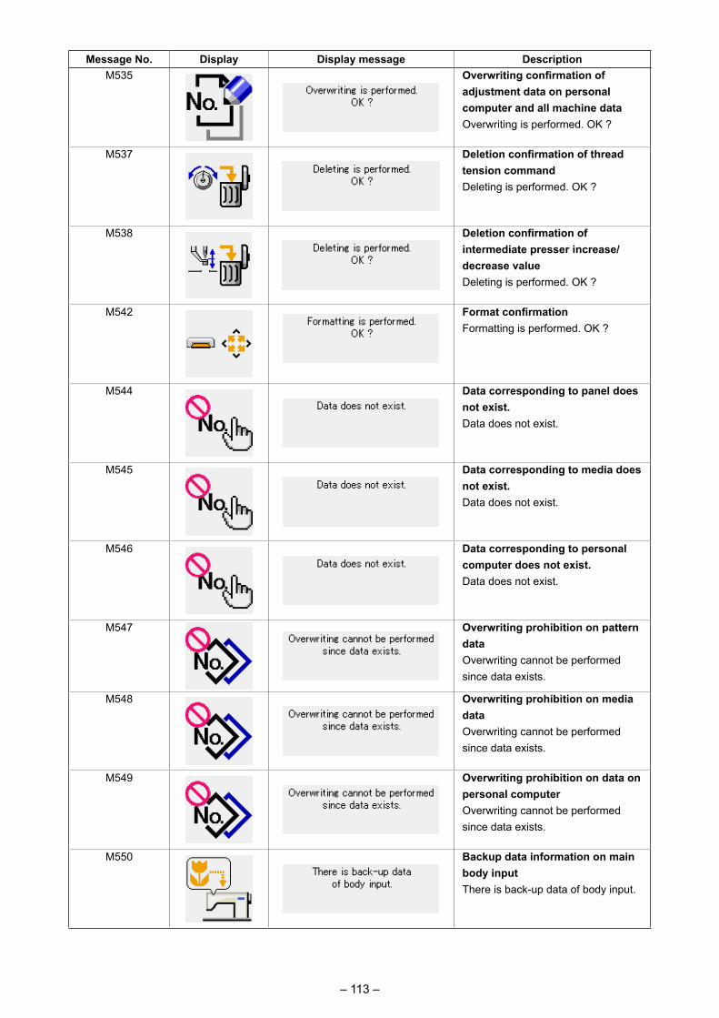
– 113 –
Message No. Display Display message DescriptionM535 Overwriting confirmation of
adjustment data on personal computer and all machine data Overwriting is performed. OK ?
M537 Deletion confirmation of thread tension commandDeleting is performed. OK ?
M538 Deletion confirmation of intermediate presser increase/decrease valueDeleting is performed. OK ?
M542 Format confirmation Formatting is performed. OK ?
M544 Data corresponding to panel does not exist. Data does not exist.
M545 Data corresponding to media does not exist.Data does not exist.
M546 Data corresponding to personal computer does not exist.Data does not exist.
M547 Overwriting prohibition on pattern dataOverwriting cannot be performed since data exists.
M548 Overwriting prohibition on media data Overwriting cannot be performed since data exists.
M549 Overwriting prohibition on data on personal computerOverwriting cannot be performed since data exists.
M550 Backup data information on main body input There is back-up data of body input.

– 114 –
Message No. Display Display message DescriptionM554 Customized data initialization
noticeCustomized key-lock data has been initialized.
M555 Customized data breakageCustomized key-lock data has broken. Initialization is performed. OK?
M556 Initialization confirmation of customized dataCustomized key-lock data is initialized. OK?
M557 Confirmation of clearance of password settingClears passwordYes or no
M653 During formattingFormatting is performed.
M669 During data readingData is being read.
M670 During data writingData is being written.
M671 During data convertingData is being converted.

– 115 –
1-1. Adjusting the height of the needle bar (Changing the length of the needle)
* Turn ON the power once, and turn OFF the power again after making the intermediate presser in the lowered state.
1) Bring needle bar ❶ down to the lowest position of its stroke. Loosen needle bar connection screw ❷ and adjust so that the upper marker line ❸ engraved on the needle bar aligns with the bottom end of the needle bar bushing lower ❹ .
2) Asillustratedintheabovefigure,changetheadjustingpositioninaccordancewiththeneedlecount. After the adjustment, turn the pulley to check for an extra load.
1. MAINTENANCE
❺ : Marker line for DP × 5❻ : Market line for DP × 17 (with needle count higher than #22)❼ : Marker line for DP × 17 (with needle count lower than #22)
1-2. Adjusting the needle-to-shuttle relation
❷
❸
❷
❸
❷
❸
❹❻
❸
❹ : Marker line for DP × 5 needle
❺ : Marker line for DP × 17 needle (with needle count higher than #22)
❻ : Marker line for DP × 17 needle (with needle count lower than #22)
❺
❶
Relation between the needle and the marker lines on the needle bar
When a DP × 5 needle is used.
When DP × 17 needle (of which needle count is lower than #22)
is used.
When DP × 17 needle (of which needle count is higher than #22)
is used.
* Turn ON the power once, and turn OFF the power again after making the intermediate presser in the lowered state.
1) Turn handwheel by hand to ascend the needle bar ❶ .
Adjust so that lower marker line ❷ on the as-cending needle bar aligns with the bottom end of the needle bar bushing lower.
III. MAINTENANCE OF SAWING MACHINE
WARNING : Turn OFF the power before starting the work so as to prevent accidents caused by abrupt start or
the sewing machine.
WARNING : Turn OFF the power before starting the work so as to prevent accidents caused by abrupt start or
the sewing machine.
❺
❹ ❸
❻❼
❶
❶
❷
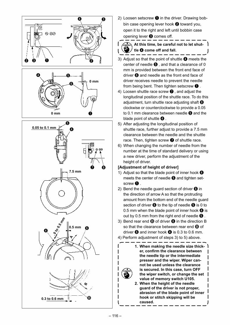
– 116 –
2) Loosen setscrew ❶ in the driver. Drawing bob-bin case opening lever hook ❷ toward you, open it to the right and left until bobbin case opening lever ❸ comes off.
At this time, be careful not to let shut-tle ❹ come off and fall.
3) Adjust so that the point of shuttle ❹ meets the center of needle ❺ , and that a clearance of 0 mm is provided between the front end face of driver ❻ and needle as the front end face of driver receives needle to prevent the needle from being bent. Then tighten setscrew ❶ .
4) Loosen shuttle race screw ❼ , and adjust the longitudinal position of the shuttle race. To do this adjustment, turn shuttle race adjusting shaft ❽ clockwise or counterclockwise to provide a 0.05 to 0.1 mm clearance between needle ❺ and the blade point of shuttle ❹ .
5) After adjusting the longitudinal position of shuttle race, further adjust to provide a 7.5 mm clearance between the needle and the shuttle race. Then, tighten screw ❼ of shuttle race.
6) When changing the number of needle from the number at the time of standard delivery or using a new driver, perform the adjustment of the height of driver.
[Adjustment of height of driver]1) Adjust so that the blade point of inner hook ❹
meets the center of needle ❺ and tighten set-screw ❶ .
2) Bend the needle guard section of driver ❻ in the direction of arrow A so that the protruding amount from the bottom end of the needle guard section of driver ❻ to the tip of needle ❺ is 0 to 0.5 mm when the blade point of inner hook ❹ is out by 0.5 mm from the right end of needle ❺ .
3) Bend rear end B of driver ❻ in the direction B so that the clearance between rear end B of driver ❻ and inner hook ❹ is 0.3 to 0.6 mm.
4) Perform adjustment of steps 3) to 5) above.
1. When making the needle size thick-er, confirm the clearance between the needle tip or the intermediate presser and the wiper. Wiper can-not be used unless the clearance is secured. In this case, turn OFF the wiper switch, or change the set value of memory switch U105.
2. When the height of the needle guard of the driver is not proper, abrasion of the blade point of inner hook or stitch skipping will be caused.
0.05 to 0.1 mm
7.5 mm
❺❹
❼ ❽
0 to
0.5
mm
❹
A
0.5 mm ❻
B
B
❹
❶❸❷
❸
❷
❶
❺❹
❻
0 mm
0 mm
0.3 to 0.6 mm

– 117 –
1-3. Height and angle of the work clamp
1) Loosen screws ❷ located on the right and left sides of feed bracket ❶ . Moving cloth presser stopper ❸ to the direction B will increase the height of feeding frame.
2) After the adjustment of the height of the feed-ing frame, securely tighten the screws ❷ .
WARNING : Turn OFF the power before starting the work so as to prevent accidents caused by abrupt start or
the sewing machine.
❶ ❸
❷A
B
❺
❹
❻
❼
❽
If plastic work clamp ❹ is set on feeding frame ❺ with the work clamp remained at the factory-adjusted height at the time of delivery, needle tip ❻ can interfere with plastic work clamp ❹ . To prevent the interference, adjust to decrease the work clamp height or set plastic work clamp ❹ with feeding frame ❺ held lowered by hand.
3) If the feed bracket is moved to its forward end for adjusting the work clamp height etc., when the power to the sewing machine is in the OFF state, top end of wiper ❼ interferes with head of work clamp foot setscrew ❽ . So, be careful.
* As long as the power to the sewing machine is in the ON state, no interference between top end of wiper ❼ and head of work clamp foot setscrew ❽ occurs when the feed brack-et is moved within its X-Y movable range.
(1) Height of the work clamp (S type)
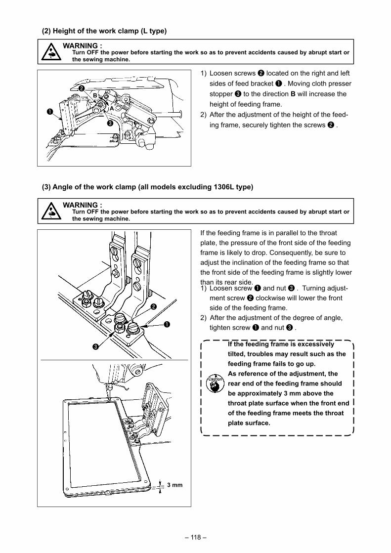
– 118 –
1) Loosen screws ❷ located on the right and left sides of feed bracket ❶ . Moving cloth presser stopper ❸ to the direction B will increase the height of feeding frame.
2) After the adjustment of the height of the feed-ing frame, securely tighten the screws ❷ .
WARNING : Turn OFF the power before starting the work so as to prevent accidents caused by abrupt start or
the sewing machine.
(2) Height of the work clamp (L type)
3 mm
WARNING : Turn OFF the power before starting the work so as to prevent accidents caused by abrupt start or
the sewing machine.
If the feeding frame is in parallel to the throat plate, the pressure of the front side of the feeding frame is likely to drop. Consequently, be sure to adjust the inclination of the feeding frame so that the front side of the feeding frame is slightly lower than its rear side.1) Loosen screw ❶ and nut ❸ . Turning adjust-
ment screw ❷ clockwise will lower the front side of the feeding frame.
2) After the adjustment of the degree of angle, tighten screw ❶ and nut ❸ .
If the feeding frame is excessively tilted, troubles may result such as the feeding frame fails to go up.As reference of the adjustment, the rear end of the feeding frame should be approximately 3 mm above the throat plate surface when the front end of the feeding frame meets the throat plate surface.
(3) Angle of the work clamp (all models excluding 1306L type)
❶
❸
❷
❶
❸
A
B❷
– 119 –
1-5. The moving knife and counter knife
1.0 mm
1) Loosen adjusting screw ❶ so that a clearance of 18.5 mm is provided between the front end of the throat plate and the top end of thread trimmer lever, small ❸ . To adjust, move the moving knife in the direction of arrow.
2) Loosen setscrew ❺ so that a clearance of 1.0 mm is provided between needle hole guide ❷ and counter knife ❹ . To adjust, move the counter knife.
Throat plate
WARNING : Turn OFF the power before starting the work so as to prevent accidents caused by abrupt start or
the sewing machine.
1-4. Adjusting the vertical stroke of the intermediate presser
* Turn ON the power once, and turn OFF the power again after making the intermediate presser in the lowered state.
1) Remove face cover.2) Turn handwheel to make the needle bar come
down to its lowest point.3) Loosen hinge screw ❶ and move it to the di-
rection A to increase the stroke.4) When marker dot A is aligned with the right
side of the outer periphery of washer ❷ , the vertical stroke of the intermediate presser becomes 4 mm. And, when marker dot B is aligned with the right side of the outer periphery of the washer, it becomes 7 mm. (The vertical stroke of the intermediate presser is factory-set to 4 mm at the time of delivery.)
By removing the rubber plug in the face plate cover, adjustment can be performed without removing the face plate cover.
WARNING : Turn OFF the power before starting the work so as to prevent accidents caused by abrupt start or
the sewing machine.
❶
AB
❷
A
❶
❷
❺❹
❸
After the origin retrieval, press the SET READY key on the IP panel to verify that a clearance of 0.5 mm or more is provid-ed between the top end of moving knife and the top end of needle thread clamp. If a clearance of 0.5 mm or more cannot be secured, adjust the position of mov-ing knife within 18.5 ± 0.5 mm to secure the specified clearance.
18.5 mm
0.5 mm or more

– 120 –
1-6. Needle thread clamp device
When thread is caught at top end ❶ of the thread clamp, thread clamp becomes incomplete and sewing trouble at the sewing start will be caused. Thread waste and lint are likely to accumulate in the sections which are shown in the circles. The sections should therefore be periodically cleaned by removing the throat plate and by blowing air through hole ❸ by removing rubber plug ❷.
WARNING : Turn OFF the power before starting the work so as to prevent accidents caused by abrupt start or
the sewing machine.
❶
1-7. Thread breakage detector plate
1) Adjust so that thread breakage detector plate ❶ is always in contact with thread take-up spring ❷ in the absence of needle thread. (Slack : approx. 0.5 mm)
2) Whenever the stroke of thread take-up spring ❷ has been changed, be sure to readjust thread breakage detector plate ❶ . To make this adjustment, loosen screw ❸ .
Adjust so that thread breakage detec-tor plate ❶ does not touch any adja-cent metallic parts other than thread take-up spring ❷ .
When polyethylene oiler ❶ becomes filled with oil, remove polyethylene oiler ❶ and drain the oil.
1-8. Draining waste oil
❶
❸
❶
❷
❷❸

– 121 –
1-10. Replacing the fuse
WARNING :1. To avoid electrical shock hazards, turn OFF the power and open the control box cover after about
five minutes have passed.2. Open the control box cover after turning OFF the power without fail. Then, replace with a new fuse
with the specified capacity.
The machine uses the following three fuses :❶ For pulse motor power supply protection 5A (time-lag fuse)❷ For solenoid and pulse motor power supply
protection 3.15A (time-lag fuse)❸ For control power supply protection 2A (fast-blow type fuse)
1) Loosen setscrew ❶ and remove setscrew ❶ .2) When screwing in adjustment screw ❷ ,
the amount of oil of oil pipe, left ❹ can be reduced.
3) After the adjustment, screw in setscrew ❶ and fix it.
1. The state of standard delivery is the position where ❸ is lightly screwed in and returned by 4 turns.
2. When reducing the amount of oil, do not screw in the screw at once. Observe the state for approximate-ly half a day at the position where ❸ is screwed in and returned by 2 turns. If reducing is excessive, worn-out of the hook will result.
1-9. Amount of oil supplied to the hook
❶
❶
❷
❹
❸
❷
❸

– 122 –
1-11. Changing the voltage of 100 ⇔ 200V
WARNING : To prevent personal injuries caused by electric shock hazards or abrupt start of the sewing machine, carry out the work after turning OFF the power switch and a lapse of 5 minutes or more. To prevent accidents caused by unaccustomed work or electric shock, request the electric expert or engineer of our dealers when adjusting the electrical components.
Changing procedure of the changeover connector1. Turn OFF the power source with the power switch
after confirming that the sewing machine has stopped.
2. Draw out the power cord from the power plug sock-et after confirming that the power switch is turned OFF. Then wait for five minutes or more.
3. Remove the front cover.4. Remove four screws fixing the rear cover of the
control box and slowly open the rear cover.
A. In case of using with 3-phase 200V to 240V• Changing the changeover connector Connect to 200V the 100→200V changeover
connector of FLT p.c.b. ❶ located on the side of the Box Side of the control box.
• Connect the crimp style terminal of AC input cord to the power plug as shown in the figure.
B. In case of using with single phase 100V to 120V• Changing the changeover connector Connect to 100V the 100→200V changeover
connector of FLT p.c.b. ❶ located on the side of the Box Side of the control box.
• Connect the crimp style terminal of AC input cord to the power plug as shown in the figure.
(Caution) Securely perform the insulation treatment to the red terminal which is not used with insulation tape or the like. (When the insulation is insufficient, there is a danger of electric shock or leakage current.)
C. In case of using with single phase 200V to 240V • Changing the changeover connector Connect to 200V the 100→200V changeover
connector of FLT p.c.b. ❶ located on the side of the Box Side of the control box.
• Connect the crimp style terminal of AC input cord to the power plug as shown in the figure.
(Caution) Securely perform the insulation treatment to the red terminal which is not used with insulation tape or the like.
(When the insulation is insufficient, there is a danger of electric shock or leakage current.)
5. Check that the change has been performed with-out fail before closing the rear cover.
6. Be careful that the cord is not pinched between the rear cover and the control box main unit. Close the rear cover while pressing the lower side of rear cover, and tighten four screws.
It is adaptable to the voltage of single phase 100V to 120V/3-phase 200V to 240V by changing the voltage changeover connector mounted on FLT p.c.b.(Caution) When the changing procedure is wrong, the control box will be broken. So, be very careful.
❶
GREEN
(Plug side)
REDBLACKWHITE
GREEN/YELLOW
A
B
L1 L2 L3
T1 T2 T3
WHITEBLACKRED
GREEN
(Plug side)
GREEN/YELLOW
C
GREEN
(Plug side)
GREEN/YELLOW
L1 L2
T1 T2
L1 L2 L3
T1 T2 T3
(Box side)
(Box side)
(Box side)
L3
T3
REDBLACKWHITE
REDBLACKWHITE
WHITEBLACKRED
WHITEBLACKRED
– 123 –
1. Error code E220 or E221 is displayed again unless UMBER OF STITCHES D is changed to "0" after replenishing the designated places with grease. When E221 is displayed, the sewing machine fails to operate. So, be careful.
2. When GREASE APPLYING POSITION DISPLAY but-
ton C is pressed in each screen, the grease
applying position can be confirmed in the panel display. Be sure, however, to perform the grease applying after turning OFF the power.
1-12. Replenishing the designated places with grease
C
B
C
B
* Perform grease supplement when the errors below are displayed or once a year (either one which is earlier).
If grease has decreased due to cleaning of the sewing machine or any other reasons, be sure to immediately add grease.
When the sewing machine has been used for a certain number of stitches, error "E220 Grease-up warning" is displayed. This display informs the operator of the time of replenishing the designated places with grease. Be sure to replenish the places with the grease below. Then call the memory switch U245, press CLEAR button
A and set NUMBER OF STITCHES D to "0".Even after the display of the error "E220 Grease-up warning",
when RESET key B is pressed, the error is released, and the sewing machine can be continuously used. Afterwards, howev-er, error code "E220 Grease-up warning" is displayed every time the power is re-turning ON.In addition, when the sewing machine is used further for a certain period of time without replenishing the places with grease after the display of error No. E220, error "E221 Grease-up error" is displayed and the sewing machine fails to operate since the error cannot be released even when the RESET key is pressed.
When error "E221 Grease-up error" is displayed, be sure to replen-ish the designated places below with grease. Then call the mem-
ory switch U245, press CLEAR button A and set NUMBER OF STITCHES D to "0".
When RESET key B is pressed without replenishing the designated places with grease, error code "E221 Grease-up warn-ing" is displayed every time the power is re-turning ON afterwards and the sewing machine fails to operate. So, be careful.
A
C
D

– 124 –
(1) Location where exclusive grease is provided Two different types of JUKI Grease A ❶ and B ❷ and an exclusive coupling and setscrew for JUKI
Grease B are provided at the location as shown in the illustration. Add grease periodically (when the grease runout warning No. E220 is displayed on the panel or once a year) to points to be ap-plied with grease.
If grease has decreased due to cleaning of the sewing machine or any other reasons, be sure to immediately add grease.
Do not use Grease A and Grease B with mixed. Be sure to use the specified grease without fail. The grease filling coupling and setscrew should be used when applying JUKI Grease B. They should not be used for JUKI Grease A.
Spare parts No.JUKI Grease A 10g tube 40006323
100g tube 23640204JUKI Grease B 10g tube 40013640
❶
When the grease runs short, be sure to purchase new grease.
JUKI Grease A ❶JUKI Grease B ❷
(2) Points to be applied with JUKI Grease A
WARNING : Turn OFF the power before starting the work so as to prevent accidents caused by abrupt start
or the sewing machine. In addition, attach the covers which have been removed before operation back in place.
Use grease tube A (part number: 40006323) supplied with the unit for adding grease to any points other than the points specified below. If any grease other than the specified one is used, the related components can be damaged.
■ Adding grease to the oscillating rock shaft gear section1) Tilt the sewing machine and remove grease cover ❶ .2) Apply JUKI Grease A onto the gear section of oscil-
lating rock shaft and the periphery of the hook driving shaft.
3) Apply JUKI Grease A also onto the felt surface of grease cover ❶ .
If the grease has decreased due to clean-ing, air blow or other reasons, apply grease again without exceptions.

– 125 –
❷❻
❻
❷
❼
❶
B A
❽❾
❺❹
■ Adding grease to the needle bar upper and lower bushings section, slide block section and intermediate presser bar lower bushing section
1) Open the frame cover to remove intermediate presser auxiliary spring B ❶ .
2) Apply JUKI Grease A onto periphery of needle bar ❷ . Turn the sewing machine by hand to apply grease onto the entire periphery of the needle bar.
Turn needle bar upper bushing grease cover ❸ in the direction of arrow A to add grease through the grease inlet. After completion of the procedure, turn the needle bar upper bushing grease cover in the direction of arrow B to return to its home position.
Remove setscrew ❹ from the needle bar lower bushing grease hole. Put JUKI Grease A through hole ❺ and tighten setscrew ❹ to fill inside the busing with the grease.
3) Apply JUKI Grease A also onto groove section ❻ of the slide block.
4) Apply JUKI Grease A onto periphery of inter-mediate presser bar ❼ .
Remove setscrew ❽ from the intermediate presser bar bushing grease hole. Put JUKI Grease A through inlet ❾ . Tighten screw ❽ to fill inside the bushing with JUKI Grease A.
1. Do not wipe off the grease applied onto the periphery of needle bar inside the frame. If the grease has decreased due to cleaning, air blow or other reasons, apply grease again without exceptions.
2. When operating the sewing ma-chine, turn the needle bar upper bushing grease cover in direction B to close grease inlet � .
3. The rear face of the needle bar crank rod has projection � with a sharp edge. So, care should be tak-en to the projection. Never put your finger to the rear face of the needle bar crank rod during greasing pro-cedure.
❸
�
�

– 126 –
■ Adding grease onto the eccentric cam section
Use grease tube B (part number: 40013640) supplied with the unit for adding grease to any points other than the points specified below. If any grease other than the specified one is used, the related components can be damaged.
1) Tilt the machine head and remove the grease cover ❶ .
2) Fill coupling ❹ supplied with the unit with grease through JUKI Grease B tube ❺ .
3) Remove setscrew ❸ in oscillator gear ❷ and screw in joint ❹ into the screw hole.
4) Sink screw ❻ supplied with the unit into the coupling to add the JUKI Grease B.
5) Securely tighten setscrew ❸ which has been removed after replenishing with the grease.
■ Adding grease onto the oscillating rock shaft pin section
(3) Points to be applied with JUKI Grease B
The eccentric cam section can be sufficiently filled with grease by adding the grease while turning the main shaft of sewing machine.
1) Open crank rod cover ❶ .2) Remove setscrew ❸ from the grease
inlet cover located at periphery of crank rod ❷ .
3) Fill coupling ❹ with grease through JUKI Grease B tube ❺ .
4) Sink screw ❻ supplied with the unit into the coupling to add the grease.
5) After adding the grease, securely tighten setscrew ❸ which has been removed.
❷
❶
❹❷
❹ ❺
❻
❸
❷❶
❸
❹❻
❺❹
❶❷
❻❼
❽❺
❹ ❸
■ Grease supplement to the face plate section1) Open the face plate cover.2) Add the JUKI Grease B onto the felt sections
(3 locations), peripheral shoulder screw, ful-crums ❶ to ❼ and guide groove section ❽ .
– 127 –
(4) Applying grease to other sections
■ Adding grease to X-feed gear sectionGrease film on the feed gear is likely to run out when using the machine for sewing such a sewing shape that has continuous reverse-feed stitching as shown in the figure at the left. To keep the grease film on the feed gear, carry out the follow-ing two steps of procedure.① Add JUKI-specified grease TEMPLEX N2
(JUKI part number: 13525506) to the gear section approximately at least once a month.
② Use the machine with the retainer correction mode (U91) activated. Another preventive measure is to manually move the feed gear in a complete stroke before turning the power ON, so as to spread the grease over the en-tire tooth surface of the gear to cover it with a grease film.
For the sewing shape as shown in the figure, only a part of the gear is continuously used. Apply the grease to the mesh of the gear which is used for sewing.
■ Grease supplement to X guide shaft bearing1) Apply JUKI Grease B onto X guide shaft ❶
and presser plate ❷ .
❶
❷

– 128 –
1-13. Troubles and corrective measures (Sewing conditions)
Trouble Cause Corrective measures Page1. The needle
thread slips off at the start of bar-tacking.
① Stitches are slipped at the start. ◦ Adjust the clearance between the needle and the shuttle to 0.05 to 0.1 mm.
116
◦ Set soft-start sewing at the start of bartacking.
96
② The needle thread remaining on the needle after thread trimming is too short.
◦ Correct the thread tension release timing of the thread tension controller No. 2.
◦ Increase the tension of the thread take-up spring, or decrease the tension of the thread tension controller No. 1.
22, 23
③ The bobbin thread is too short. ◦ Decrease the tension of the bobbin thread.
22
◦ Increase the clearance between the needle hole guide and the counter knife.
119
④ Needle thread tension at 1st stitch is too high.
◦ Decrease the tension at 1st stitch.
⑤ Thread clamp is unstable (material is apt to be expanded, thread is hard to slide, thread is thick, etc.).
◦ Decrease the number of rotation at 1st stitch at the sewing start. (Extent of 600 to 1,000 rpm)
◦ Increase the number of stitches of thread clamp to 3 to 4 stitches.
⑥ Pitch at 1st stitch is too small. ◦ Make the pitch at 1st stitch longer.◦ Decrease the needle thread tension at
1st stitch.2. Thread often
breaks or synthetic fiber thread splits finely.
① The shuttle or the driver has scratches.
◦ Take it out and remove the scratches using a fine whetstone or buff.
② The needle hole guide has scratches.
◦ Buff or replace it.
③ The needle strikes the intermediate presser foot.
◦ Correct the position of the intermediate presser foot.
23
④ Fibrous dust is in the groove of the shuttle race.
◦ Take out the shuttle and remove the fibrous dust from the shuttle race.
⑤ The needle thread tension is too high.
◦ Reduce the needle thread tension. 22
⑥ The tension of the thread take-up spring is too high.
◦ Reduce the tension. 23
⑦ The synthetic fiber thread melts due to heat generated on the needle.
◦ Use silicone oil. 130
⑧ When taking up thread, thread is pierced with needle tip.
◦ Lower the needle bar height from the engraved marker line by a half of the line to as much as the line.
◦ Check the rough state of needle tip.◦ Use the ball-pointed needle.
3. The needle often breaks.
① The needle is bent. ◦ Replace the bent needle. 19
② The needle strikes the intermediate presser foot.
◦ Correct the position of the intermediate presser foot.
23
③ The needle is too thin for the material.
◦ Replace it with a thicker needle according to the material.
④ The driver excessively bends the needle.
◦ Correctly position the needle and the shuttle.
116
4. Threads are not trimmed.
① The counter knife is dull. ◦ Replace the counter knife.② The difference in level between
the needle hole guide and the counter knife is not enough.
◦ Increase the bend of the counter knife.
③ The moving knife has been improperly positioned.
◦ Correct the position of the moving knife.
119
(Bobbin thread only) ④ The last stitch is skipped. ◦ Correct the timing between the needle and the shuttle.
116
⑤ Bobbin thread tension is too low. ◦ In crease the bobbin thread tension.⑥ Flopping of cloth ◦ Lower the intermediate presser height
of the last stitch.

– 129 –
Trouble Cause Corrective measures Page5. Stitch skipping
often occurs.① The motions of the needle
and shuttle are not properly synchronized.
◦ Correct the positions of the needle and shuttle.
116
② The clearance between the needle and shuttle is too large.
◦ Correct the positions of the needle and shuttle.
116
③ The needle is bent. ◦ Replace the bent needle. 19④ The driver excessively bends the
needle.⑤ Length of needle thread
remaining after thread trimming is too long. (In the case of stitch skipping within the 2nd to 10th stitch from the beginning of sewing)
◦ Correctly position the driver.
◦ Reduce the thread take-up spring pressure or increase the thread tension applied by the thread tension controller No. 1.
116
22, 23
6. The needle thread comes out on the wrong side of the material.
① The needle thread tension is not high enough.
◦ Increase the needle thread tension. 22
② The tension release mechanism fails to work properly.
◦ Check whether or not the tension disc No. 2 is released during bar-tracking.
③ The needle thread after thread trimming is too long.
◦ Increase the tension of the thread tension controller No. 1.
◦ Correct the position of the moving knife.
22
④ Number of stitches is too few. ◦ Turn OFF the thread clamp.⑤ When sewing length is short (End
of needle thread protrudes on the wrong side of sewing product.)
◦ Turn OFF the thread clamp.
⑥ Number of stitches is too few. ◦ Use the lower plate, the hole of which is larger than the presser.
7. Thread end of the 1st stitch comes out on the right side of the material.
① Stitch skipping at the 1st stitch ◦ Adjust the hook timing faster by a 1/2 stitch.
② Needle used and thread used are thick in terms of the inner diameter of the intermediate presser.
◦ Increase the inner diameter of intermediate presser.
③ Intermediate presser is not properly positioned in terms of the needle.
◦ Adjust the eccentricity between intermediate presser and needle so that needle enters in the center of intermediate presser.
8. Threads break at time of thread trimming.
① The moving knife has been improperly position.
◦ Correct the position of the moving knife.
119
9. The thread clamp is entangled with needle thread.
① The needle thread at the sewing start is too long.
◦ Tighten thread tension controller No. 1 and make the length of needle thread 40 to 50 mm.
26
10. Uneven length of the needle thread
① The tension of thread take-up spring is too low.
◦ Increase the tension of the thread take-up spring.
23
11. The length of needle thread does not become short.
① The tension of thread tension controller No. 1 is too low.
◦ Increase the tension of thread tension controller No. 1.
22
② The tension of thread take-up spring is too high.
◦ Decrease the tension of thread take-up spring.
23
③ The tension of thread take-up spring is too low and motion is unstable.
◦ Increase the tension of thread take-up spring and lengthen the stroke as well.
12. The knotting section of bobbin thread at 2nd stitch at the sewing start appears on the right side.
① Idling of bobbin is large. ◦ A just the position of the moving knife. 119② The bobbin thread tension is too
low.◦ Increase the bobbin thread tension. 22
③ The needle thread tension at 1st stitch is too high.
◦ Decrease the needle thread tension at 1st stitch.
◦ Turn OFF the thread clamp.
13. Wiper fails to work. (Return is defective.)
① Needle entry of the last needle is the same as that of the sewing start, and the resistance of thread and cloth is large.
◦ Shift the needle entry point of the last needle.

–130–
2-1. Table of Needle hole guide
2. OPTIONAL
2-2. Silicon oil tank
WARNING :Turn OFF the power before starting the work so as to prevent accidents caused by abrupt start or the sewing machine.
Remove take up thread guide No. 1 ❸ and secure silicon oil tank base ❷.Fix silicon oil tank ❶ (B3532223C00) with themagnet.
1. If the thread twists hard on silicon oil tank base ❷ (B2535210000), reverse the direction of winding the thread.
2. For fixing the silicon oil tank base, use two M4 screws ❹ .
(Part No. of commendable screw : SM4040855SP)
Needle used Needle hole guideSize Part No. Needle hole diameter Application
#09to#11 B242621000C ø 1.6 Forknits(OP)
#11 to #14 *1 B242621000A ø 1.6 For light-weight to medium-weight materials (Stype)
#14 to #18 *2 B242621000B ø2.0 For medium-weight to heavy-weight materials (Htype)
#18 to #21B242621000D ø 2.4
Forheavy-weightmaterials(OP)B242621000F ø3.0
#22 to #25 B242621000G ø3.0(withacounterbore) Forextraheavy-weightmaterials(OP)
#18 to #25 B242621000H ø3.0(eccentrichole) For heavy-weight materials to prevent skip-stitching(OP)
Needle used Intermediate presserSize Part No. Size (øA×øB×H×L)
#09to#11 B1601210D0E(OP)40023632(Standard)B1601210D0FA(OP)
ø1.6×ø2.6×5.7×37.0ø2.2×ø3.6×5.7×38.5ø2.2×ø3.6×8.7×41.5
#11 to #14 *1
#14 to #18 *2
#18 to #21 B1601210D0BA(OP) ø2.7×ø4.1×5.7×38.5#22 to #25
B1601210D0CA(OP) ø3.5×ø5.5×5.7×38.5#18 to #25
* 1:Standardinstalledneedle(DP×5#14)* 2:Standardinstalledneedle(DP×17#18)・Stype:Applicablecountofthread:#80to#20・ Htype:Applicablecountofthread:#50to#02・(OP)meanstheoptional.
H
Lø A
ø B
❸
❶
❷
❹

– 131 –
WARNING :• Do not look directly into the laser beam of the bar code reader. The laser beam can damage eyes.• Do not emit laser beam toward human eyes. The laser beam can damage eyes.• Do not look into the laser beam directly using an optical device. The laser beam can damage eyes.
CAUTION :• Be sure to use the sewing machine within the specified temperature range and the specified humidity range.• Do not connect/remove connectors with the power supplied to the sewing machine.
2-3. Bar code reader
Bar code function is a function to read the bar code and to switch to the corresponding sewing pattern for the applications such as the cassette identification etc.By reading the bar code, switching to 999 user patterns stored in the sewing machine memory and to 50 sewing data registered in the pattern button can be made.To use this function, AMS-EN bar code option (40089238) will be required.Refer to the Instruction Manual/Parts List (40089259) for the Bar-code Reader (optional) of the AMS-EN Series for details.
Specifications for the barcode readerClass 2 laser productMaximum output: 1.0mWWave length: 650nm
Safety standardJIS C 6802:2005 IEC60825-1+A2:2007
Recommended