Embed Size (px)
DESCRIPTION
SAR Project
Citation preview

SAR Products/Solutions and Services
Technical Support by GISTDA
Dr. Anuphao Aobpaet ([email protected])
Earth Observation Center
Geo-Informatics and Space Technology Development Agency
(Public Organization)
SAR Applications Workshop, May 20-23, 2013, GISTDA Bangkhen Office, 196 Phahonyothin,
Chatuchak, Bangkok
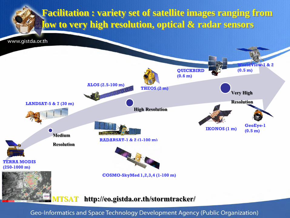
Facilitation : variety set of satellite images ranging from
low to very high resolution, optical & radar sensors
Medium Resolution
High Resolution
Very High Resolution LANDSAT-5 & 7 (30 m)
IKONOS (1 m)
QUICKBIRD
(0.6 m)
WorldView-1 & 2
(0.5 m)
GeoEye-1
(0.5 m)
RADARSAT-1 & 2 (1-100 m)
ALOS (2.5-100 m) THEOS (2 m)
TERRA MODIS
(250-1000 m)
MTSAT http://eo.gistda.or.th/stormtracker/
COSMO-SkyMed 1,2,3,4 (1-100 m)

GISTDA : Facilities of ground station
Earth Observation Center (EOC) Lat-Krabang, Bkk.
THEOS Ground Control and Receiving Station Si Racha, Chon Buri

GISTDA Ground Stations: simple configuration
http://gcudos.gistda.or.th:8080/cudos

The radius of data reception is approximately 2,500 kilometers from Bangkok.
Covering 17 countries
Satellite Data Acquisition and Services
RADARSAT-1 AND RADARSAT-2
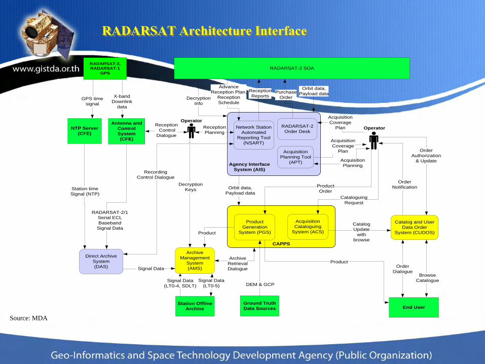
RADARSAT Architecture Interface
CAPPS
Agency Interface
System (AIS)
End User
RADARSAT-2 SOA
Product
Generation
System (PGS)
Direct Archive
System
(DAS)
Antenna and
Control
System
(CFE)
Catalog and User
Data Order
System (CUDOS)
Operator
Archive
Management
System
(AMS)
Archive
Retrieval
Dialogue
RADARSAT-2,
RADARSAT-1
GPS
X-band
Downlink
data
GPS time
signal
RADARSAT-2/1
Serial ECL
Baseband
Signal Data
Recording
Control Dialogue
Station Offline
Archive
Ground Truth
Data Sources
Signal Data
(LT0-5)
Product
Catalog
Update
with
browse
Browse
Catalogue
Acquisition
Coverage
Plan
Order
Dialogue
Product
Order
Acquisition
Planning
Signal Data
Decryption
Keys
Operator
Reception
Planning
Cataloguing
Request
NTP Server
(CFE)
Station time
Signal (NTP)
Order
Authorization
& Update
Acquisition
Cataloguing
System (ACS)
Order
Notification
DEM & GCP
Acquisition
Planning Tool
(APT)
Network Station
Automated
Reporting Tool
(NSART)
Orbit data,
Payload dataReception
ReportsDecryption
Info
Reception
Control
Dialogue
Orbit data,
Payload data
Advance
Reception Plan,
Reception
Schedule
RADARSAT-2
Order Desk
Purchase
Order
Acquisition
Coverage
Plan
Product
Signal Data
(LT0-4, SDLT)
Source: MDA
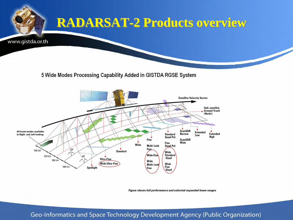
RADARSAT-2 Products overview

RADARSAT-2 Polarization Options per Beam/Mode
Source: http://gs.mdacorporation.com/products/sensor/radarsat2/RS2_Product_Description.pdf
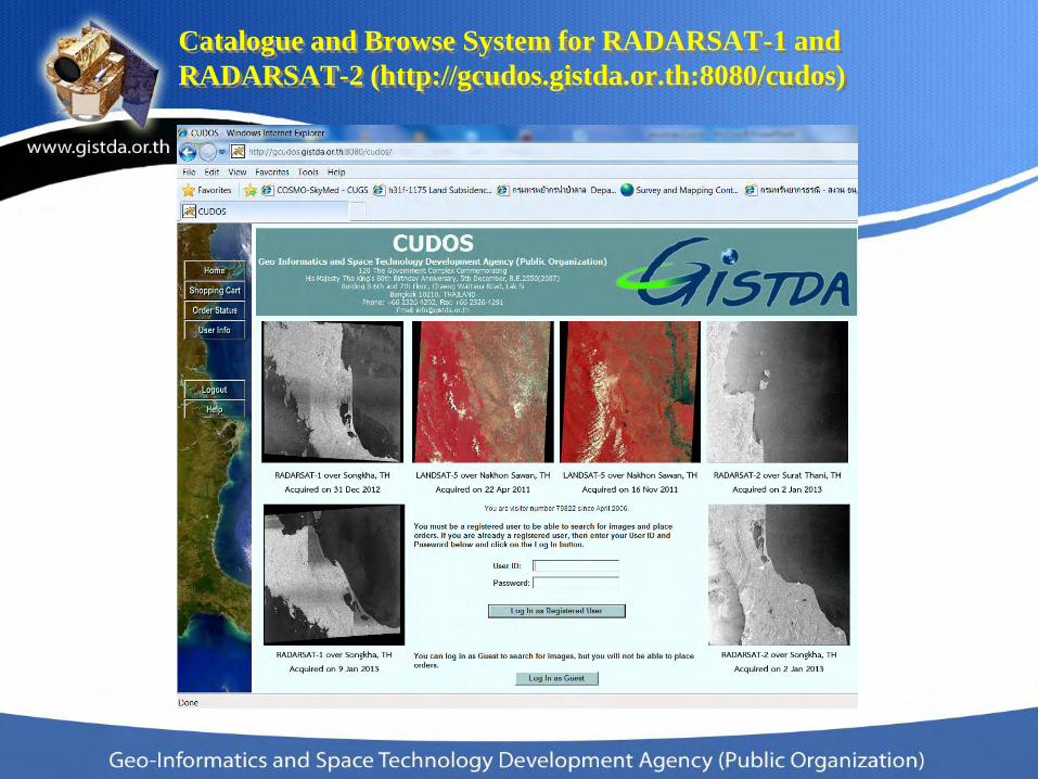
Catalogue and Browse System for RADARSAT-1 and
RADARSAT-2 (http://gcudos.gistda.or.th:8080/cudos)

Product Generation System

Products delivery: RADARSAT-2 Wide MF Mode Coverage
Blu-ray disk media
COSMO-SkyMed 1, 2 , 3, 4

Source: eGEOS
Customer User Terminal Architecture Overview
SRI-RACHA SITE
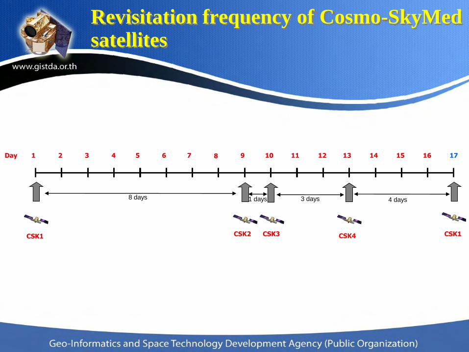
Revisitation frequency of Cosmo-SkyMed satellites
Day 1 2 3 4 5 6 7 8 9 10 11 12 13 14 15 16 17
CSK1 CSK1 CSK3 CSK2 CSK4
8 days 3 days 4 days 1 days

COSMO-SkyMed services
COSMO-SkyMed Ground segment system: for programming, acquiring, receiving and
processing COSMO-SkyMed data
• CUT system to be installed at GISTDA ground receiving
station at Siracha site
• Near Real Time data acquisition capability
Application Platforms for generation of value added products and service deployment
from CSK data
• Application platform System to be installed at GISTDA HQ
• Mean functionalities:
– Disaster assessment for flooding- FLOOD- flood extraction and monitoring
– Land Management- MTC- agricultural &forest monitoring
– Maritime surveillance- TE.M.A.S.- oil spill detection and monitoring
– Data Access and Exploitation Facility: operational procedures
implementation, products storage, management and analysis (GeoDatabase)
Source: eGEOS
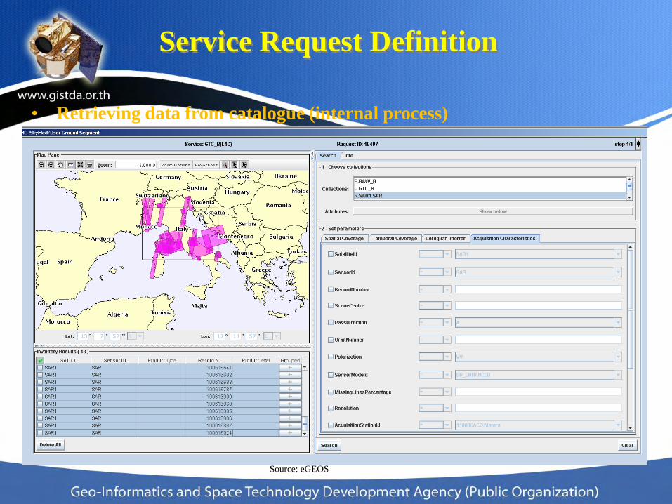
• Retrieving data from catalogue (internal process)
Service Request Definition
Source: eGEOS
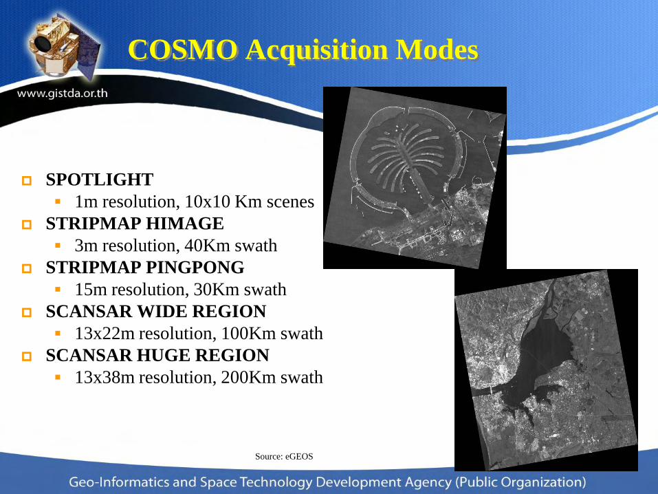
COSMO Acquisition Modes
SPOTLIGHT
1m resolution, 10x10 Km scenes
STRIPMAP HIMAGE
3m resolution, 40Km swath
STRIPMAP PINGPONG
15m resolution, 30Km swath
SCANSAR WIDE REGION
13x22m resolution, 100Km swath
SCANSAR HUGE REGION
13x38m resolution, 200Km swath
Source: eGEOS
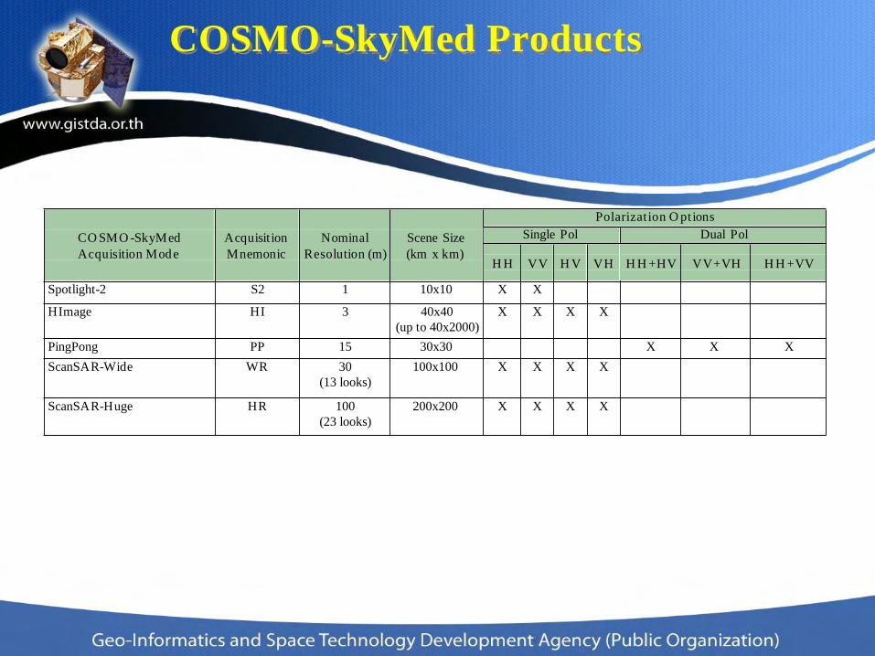
COSMO-SkyMed Products
CO SMO -SkyMed
Acquisition Mode
Acquisit ion
Mnemonic
Nominal
Resolution (m)
Scene Size
(km x km)
Polarizat ion O ptions
Single Pol Dual Pol
H H VV H V VH H H +HV VV+VH H H +VV
Spotlight-2 S2 1 10x10 X X
HImage HI 3 40x40
(up to 40x2000)
X X X X
PingPong PP 15 30x30 X X X
ScanSAR-Wide WR 30
(13 looks)
100x100 X X X X
ScanSAR-Huge HR 100
(23 looks)
200x200 X X X X
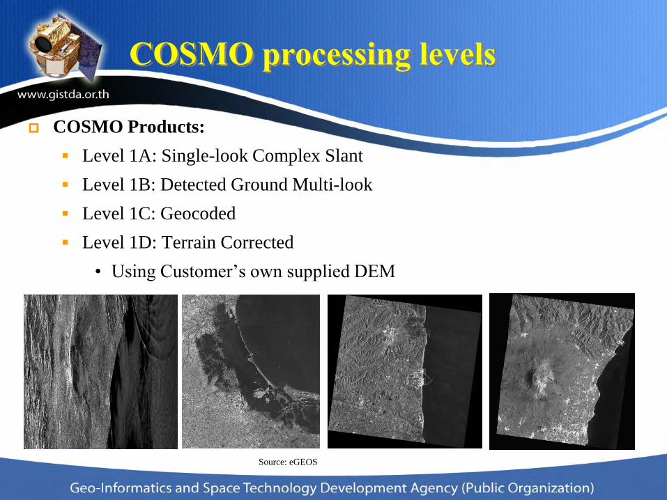
COSMO processing levels COSMO Products:
Level 1A: Single-look Complex Slant
Level 1B: Detected Ground Multi-look
Level 1C: Geocoded
Level 1D: Terrain Corrected
• Using Customer’s own supplied DEM
Source: eGEOS

An example – Samut Prakan
Example: Commercial Synthetic Aperture Radar Satellite Application Guide
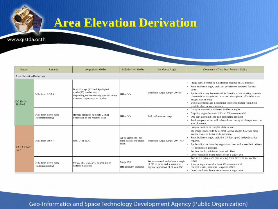
Area Elevation Derivation
characteristics (vegetation cover and atmospheric effects between
- Use of ascending and descending to get information from both
- One pair ascending, one pair descending required
System Scenar io Acquisition Mod es Polarizat ion Modes Incid ence Angle Comments / Descr ibed Results / Utility
Area Elevation Derivat ion
CO SMO -SkyMed
DEM from InSAR
Both HImage (HI) and Spotlight-2modes(S2) can be used.
Depending on the working scenario morethan one couple may be required
HH or VVIncidence Angle Range: 20 -35
- Image pairs in complex data format required (SCS product).
- Same incidence angle, orbit and polarization required for each
series
- Applicability may be restricted in function of the working scenario
images acquisitions)
possible observation directions
DEM from stereo pairs(Radargrammetry)
HImage (HI) and Spotlight-2 (S2)depending on the required scale
HH or VV Full performance range
- Data pair acquired at different incidence angles
- Disparity angles between 15 and 25 recommended
- Small temporal offset will reduce the occurring of changes over the
area of interest
- For best results, minimize temporal offset
- Angular separation of at least 15 recommended
System Scenar io Acquisition Modes Polarizat ion Modes Incidence Angle Comments / Descr ibed Results / Utility
RADARSAT
1 & 2
DEM from InSAR UW, U, or SLAAll polarizations, but same within one imagestack
Incidence Angle Range: 20 - 45
- Imagery must be in complex data format.
- The image stack could be as small as two images however more
images results in better DEM accuracy.
- Same incidence angle, orbit (i.e. 24 days apart) and polarization
required.
- Applicability restricted by vegetation cover and atmospheric effects.
- HH polarization preferred.
- Lower resolution beam modes cover a larger area
DEM from stereo pairs
(Radargrammetry)
MFW, MF, UW, or U depending onvertical resolution
Single Pol.
HH generally preferred
We recommend an incidence angleof 30 or more and a minimumangular separation of at least 15
- Two stereo pairs, each pair viewing from different sides of theterrain
- For best results, minimize temporal offset.
- Lower resolution beam modes cover a larger area

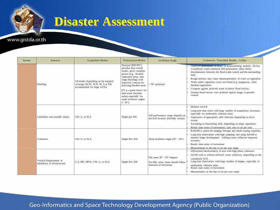
Disaster Assessment
Steeper incidence angles may be
morphology and target type
a pre-event imagery also from optical satellites.
- Ascending and descending orbits required may improve results
to moderate wind conditions HH polarization allow better
land.
Baseline Subset Approach)
- Importance of appropriate orbit direction depending on local
number of images for moderately coherent areas.
- PSI with or without artificial corner reflectors, depending on the
System Scenar io Acquisition Modes Polarizat ion Modes Incidence Angle Comments / Descr ibed Results / Utility
CO SMO-SkyMed
Risk and vulnerability assessment
(Pre-disaster)
All modes depending on the requiredcoverage and spatial accuracy. The usageof short term interferometric couple or
series (one, three, four days) is suggestedin order to improve feature extractioncapability
Single pol. (HH or VV)
30 - 45
required in function of surface
(volume / shape)
- Monitoring of the area of interest
EarthquakesMainly HImage (HI) and Spotlight-2 (S2)
modes
Single pol. HH or VV
(mainly based on the
availability of a pre-
event image)
30 - 40 depending on the damage
assessment method used
- At near real-time conditions visual assessment of the damages using
- Long term monitoring using persistent scatterer Interferometry
techniques or Differential Interferometry.
FloodingAll modes depending on the required
coverage
Single pol. HH shows
higher contrast betweenwater and land surfaces
Full performance range (first
acquisition available) (>30 preferred)
- Choice of polarization is based on backscattering analysis. On low
discrimination between the flood (calm water) and the surrounding
Landslides and unstable slopesHImage (HI) and Spotlight-2 modes (SL
and HS)Single pol HH
full performance range depends on
the AOI location (flat/hilly terrain)
- Method: PSI (Persistent Scatterer Interferometry), SBAS (Short
- Long-term time series with large number of acquisitions necessary,
especially for moderately coherent areas.
terrain.
- Ascending or descending orbit, depending on slope exposition.
- Result: time series of movements; unit: mm per year.
VolcanoesHImage (HI) and Spotlight-2 modes (SL
and HS)Single pol. (HH or VV)
20 -35 depending on morphologyand implemented technique
- At near real-time conditions, visual assessment of the damages
using a pre-event imagery also from optical sensors.
- Long term observation with high sampling rate using PSI. Large
- Result: time series of movement, unit: mm, cm, per year.
Vertical displacement or
subsidence of infrastructure
HImage (HI), Spotlight-2 modes (SL and
HS) Single pol. (HH or VV) Steep incidence angle
- Differential Interferometry in area with high phase coherence.
considered AOI.
- Result: time series of movement; unit: mm, cm or dm per year

Disaster Assessment
the paths used by refugees.
- The usage of RGB false color composite made by both short term
50 ).
persistent scatterer Interferometry techniques or Interferogram
System Scenar io Acquisition Mod es Polarizat ion Modes Incidence Angle Comments / Descr ibed Results / Utility
Planning and management of
search and rescue operations
Spotlight-2 modes (SL and HS) and
StripMap (HI). The usage of short term
interferometric couple or series (one, three,
four days) is suggested in order to improve
feature extraction capability
Single polarization –
choice to be made
depending on the
considered application
30 - 45
Steeper incidence angles may be
required in function of surface
morphology and target type
(volume / shape)
- Mapping of the damaged urban and rural zones highlighting access.
- Mapping of the safe zones where refugee camps can be built.
- Coherent Change Detection can in desert area help in identifying
- Ascending and descending orbits depending on terrain slopes
and long term interferometric couple (R: master SAR-detected
amplitude, G: slave SAR-detected amplitude, B: interferometriccoherence) will improve both targets and changes detection andidentification
RADARSAT
1 & 2
Risk and vulnerability assessment
(pre-disaster)
All modes depending on the requiredcoverage and spatial accuracy
Dual pol provides best
overall results
Single Pol. HH for best
contrast of vegetationversus man-madeobjects
Single Pol. VV for
texture
Cross Pol. for specificvegetation types
Steep angles to penetrate sparsevegetation (close to 20 ); shallow
angles for information about vegetation and terrain (close to
- Monitoring of the area of interest
EarthquakesMFW, MF, UW, U, or SLA depending on
size of features and area coverageSingle Pol. HH
30 - 50 depending on the damage
assessment method used
- Deformation estimation based on Interferometric SAR (InSAR)
Analysis
- At near real-time conditions visual assessment of the damages using
a pre-event imagery also from optical satellites.
- Long term monitoring using differential interferometry and/or
stacking. High observation frequency, if possible, short observation
period.
- Ascending and descending orbits required.
- Unit: cm to dm per day or event
Disaster Assessment
to moderate wind conditions HH polarization allow better
land.
- Water under vegetation cover not found (e.g. mangroves, other
- Compare against archived scene to derive flood vectors.
context
- Importance of appropriate orbit direction depending on local
accuracy.
considered AOI.
moderately coherent areas.
System Scenar io Acquisition Modes Polarizat ion Modes Incidence Angle Comments / Descr ibed Results / Utility
Flooding
All modes depending on the required
coverage (SCW, SCN, W, S or FWrecommended for large AOIs)
Dual pol (HH/HV)provides best overall results, gives complete
picture (e.g., floodedvegetation areas, nearrange flooding) with
improved contrast fordetecting flooded areas
HV is a good choice for
land-water discrimi-
nation especially for
small incidence angles
(< 30 ).
> 30 preferred
- Choice of polarization is based on backscattering analysis. On low
discrimination between the flood (calm water) and the surrounding
- Rough surfaces may cause misinterpretation of water as vegetation.
flooded vegetation).
- Overlay flood vectors over archived optical image to provide
Landslides and unstable slopes UW, U, or SLA Single pol HHFull performance range depends on
the AOI location (flat/hilly terrain)
- Method: InSAR
- Long term time series with large number of acquisitions necessary,
especially for moderately coherent areas.
terrain.
- Ascending or descending orbit, depending on slope exposition.
- Result: time series of movements; unit: mm to cm per year.
Volcanoes UW, U, or SLA Single Pol. HH Steep incidence angle (20 - 30 )
- RADAR is useful for imaging through ash clouds during eruptions.
- Long term observation with high sampling rate using InSAR to
monitor bulge development. Adding corner reflectors improves
- Result: time series of movement
- Measurements in the mm to cm per year range
Vertical displacement orsubsidence of infrastructure
F, S, MF, MFW, UW, U, or SLA Single Pol. HH
Flat areas 30 - 50 degrees
For hilly areas, beam should followdirection of movement
- Differential Interferometry in area with high phase coherence.
- InSAR with or without artificial corner reflectors, depending on the
- Long term observation with large number of images, especially in
- Result: time series of movement
- Measurements in the mm to cm per year range
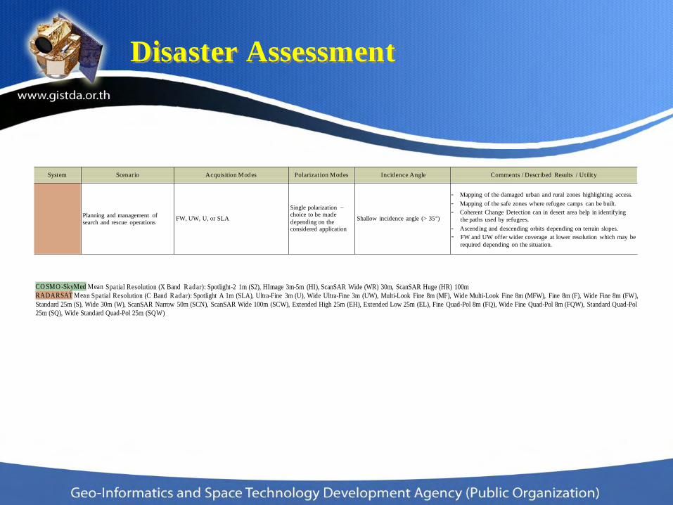
Disaster Assessment
the paths used by refugees.
- FW and UW offer wider coverage at lower resolution which may be
System Scenar io Acquisition Modes Polarizat ion Modes Incidence Angle Comments / Descr ibed Results / Utility
Planning and management ofsearch and rescue operations
FW, UW, U, or SLA
Single polarization –choice to be made
depending on theconsidered application
Shallow incidence angle (> 35 )
- Mapping of the damaged urban and rural zones highlighting access.
- Mapping of the safe zones where refugee camps can be built.
- Coherent Change Detection can in desert area help in identifying
- Ascending and descending orbits depending on terrain slopes.
required depending on the situation.
Spatial Resolution (X Band R adar): Spotlight-2 1m (S2), HImage 3m-5m (HI), ScanSAR Wide (WR) 30m, ScanSAR Huge (HR) 100m
n Spatial Resolution (C Band R adar): Spotlight A 1m (SLA), Ultra-Fine 3m (U), Wide Ultra-Fine 3m (UW), Multi-Look Fine 8m (MF), Wide Multi-Look Fine 8m (MFW), Fine 8m (F), Wide Fine 8m (FW),
Standard 25m (S), Wide 30m (W), ScanSAR Narrow 50m (SCN), ScanSAR Wide 100m (SCW), Extended High 25m (EH), Extended Low 25m (EL), Fine Quad-Pol 8m (FQ), Wide Fine Quad-Pol 8m (FQW), Standard Quad-Pol
25m (SQ), Wide Standard Quad-Pol 25m (SQW)
CO SMO -SkyMed Mean
RADARSAT Mea
Contact Information
User Service and Business Development Office
Geo-Informatics and Space Technology Development Agency
(Public Organization)
E-mail: [email protected]
www.gistda.or.th


![Quality Conrol Protocol for Level 1 Products · Quality Control Protocol for Level 1 Products ... 3 QUALITY CONTROL WORKING SCENARIOS ... [R6] CEOS SAR](https://img.dokumen.tips/doc/110x75/5c64fd3309d3f2ad6e8bf879/quality-conrol-protocol-for-level-1-quality-control-protocol-for-level-1-products.jpg)