Embed Size (px)
Citation preview

Two-way Slabs
1

Here, the slab carries load in two directions. Because the slab must transmit loads in two directions, it is referred to as a two-way slab. 2

Flat Plate: suitable span 6 to 7.5 m with LL= 3-5kN/m2
Advantages
Low cost formwork
Exposed flat ceilings
Fast
Disadvantages
Low shear capacity
Low Stiffness (notable deflection)
Two-way Slabs
3

Two-way Slabs
Flat Slab: suitable span 6 to 9 m with LL= 5-8kN/m2
Advantages
Low cost formwork
Exposed flat ceilings
Fast
High Punching shear stress
Disadvantages
Need more formwork
for capital and panels 4
Two-way Slabs
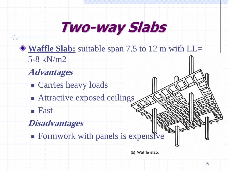
Waffle Slab: suitable span 7.5 to 12 m with LL=
5-8 kN/m2
Advantages
Carries heavy loads
Attractive exposed ceilings
Fast
Disadvantages
Formwork with panels is expensive
5

Two-way Slabs
Solid Slab systems on beams: The side ratio of the panels < 2.
6
Advantages
High resistance of lateral
and seismic loads
Forming framing system
Disadvantages
Construction Difficulties
of Formwork
Relatively high cost

7
Two-way Slabs Two Way H. B. Slabs on Beams: suitable span up to 7 m
with LL up to 5 kN/m2 (recommended for residential
buildings)
Advantages
Low cost formwork
Exposed flat ceilings
Reduce the structure weight and noise.
Low Punching shear stress
Disadvantages
Difficulties of ribs placing

Method of Analysis
(1) Elastic Analysis
Concrete slab may be treated as an elastic plate. Use
Timoshenko’s method of analyzing the structure. Finite
element analysis.
(2) Plastic Analysis
The yield method used to determine the limit state of slab
by considering the yield lines that occur in the slab as a
collapse mechanism.
The strip method, where slab is divided into strips and the
load on the slab is distributed in two orthogonal directions
and the strips are analyzed as beams. 8

Method of Analysis
The optimal analysis presents methods for minimizing
the reinforcement based on plastic analysis
(3) Nonlinear analysis
Simulates the true load-deformation characteristics of a
reinforced concrete slab with finite-element method
takes into consideration of nonlinearities of the stress-
strain relationship of the individual members.
9

BEHAVIOR OF SLABS LOADED TO FAILURE IN FLEXURE
1. Before cracking, the slab acts as an elastic plate (fig. a) 2. After cracking and before yielding of the reinforcement,
the slab no longer has a constant stiffness because the cracked regions have a lower flexural stiffness, EI, than the un-cracked regions (stage A).
3. Yielding of the reinforcement eventually starts in region of high moment. The initial yielding occurs in response to (-) moments that form localized plastic hinges at the centers of the long sides (stage A) and hence extend to short sides and at mid span (stage B).
4. The yield lines divide the plate to form a plastic mechanism, the hinges jam with increased deflection, and the slab forms a very flat compression arch. 10

BEHAVIOR OF SLABS LOADED TO FAILURE IN FLEXURE
11

Two-Way Slab Design
Static Equilibrium of Two-Way Slabs
Analogy of two-way slab to plank and beam floor Section B-B:
Moment /m width in planks
Total Moment
2
1 k-ft/ft8
qlm
2
1A-A 2 k-ft
8
lM ql 12
kN. m/m
kN.m Eq. 4-1a B-B

Analogy of two-way slab to plank and beam floor
Uniform load on each beam
Moment in one beam 2
1 2- k-ft
2 8B B
ql lM
1 k/ft2
ql
Two-Way Slab Design
Static Equilibrium of Two-Way Slabs
13
kN/m
kN.m A-A Eq. 4-1b

Total Moment in both beams
Full load was transferred east-west by the planks and then was
transferred north-south by the beams;
The same is true for a two-way slab or any other floor system.
2
21 k-ft
8B B
lM ql
Two-Way Slab Design
Static Equilibrium of Two-Way Slabs
14
kN.m B-B

DISTRIBUTION OF MOMENTS IN
SLABS
One-way slabs: Generally,
long side/short side ≥ 2 15

General Design Concepts
(1) Direct Design Method (DDM)
It is based on the total statical (Free) moment, Mo.
In this method, the slab is considered panel by panel, and Eqs. 4-1 are used to compute the total moment in each panel and in each direction. The statical moment is then divided between positive and negative moments, and these are further divided between middle strips and column strips.
16

General Design Concepts
(2) Equivalent Frame Method (EFM)
A three-dimensional building is divided into a series of two-dimensional equivalent frames by cutting the building along lines midway between columns.
The resulting frames are considered separately in the longitudinal and transverse directions of the building and treated floor by floor.
17

Basic Steps in Two-way Slab Design
Choose layout and type of slab.
Choose slab thickness to control deflection. Also, check if thickness is adequate for shear.
Choose Design method
Equivalent Frame Method- use elastic frame analysis to compute positive and negative moments
Direct Design Method - uses coefficients to compute positive and negative slab moments
1.
2.
18
3.

Basic Steps in Two-way Slab Design
Calculate positive and negative moments in the slab.
Determine distribution of moments across the width of
the slab. - Based on geometry and beam stiffness.
Assign a portion of moment to beams, if present.
Design reinforcement for moments from steps 5 and 6.
Check shear strengths at the columns
4.
5.
6.
7.
8.
19

Beam-to-Slab Stiffness Ratio, a
The ACI Code takes into account this effect by the stiffness ratio given by:
slab of stiffness flexural
beam of stiffness flexuralfa
20
Slabs built with beams stiffen the edge of the slab. This reduces deflections of panels adjacent to beams.

Beam-to-Slab Stiffness Ratio, a
With width bounded laterally by centerline of
adjacent panels on each side of the beam.
scs
bcb
scs
bcbf
IE
IE
/lIE
/lIE
4
4a
slab uncrackedan of inertia ofMoment I
beam uncracked of inertia ofMoment I
concrete slab of elasticity of Modulus E
concrete beam of elasticity of Modulus E
s
b
sb
cb
If there is no beam, af = 0 21

22

Cross section of beams as defined in ACI 13.2.4
23

24

25

EX. 4-1 Calculation of af for an Edge Beam
An 200 mm thick slab is provided with an edge beam that has a total depth of 400 mm. and a width of 300 mm. The slab and beam were cast monolithically, have the same concrete strength, and thus the same Ec. Compute af.
26
6 m
400mm
300mm
200mm

1. Compute Ib. The cross section of the beam is as shown below . The centroid of this beam is located at 175 mm. from the top of the slab
2. Compute Is. Is is computed for the shaded portion of the slab
27
300 200mm
200
200
C G
3.15 m

3. Compute af.
28

29
Minimum Slab Thickness for Two-way Construction
The ACI Code 9.5.3 specifies a minimum slab thickness
to control deflection.
There are three empirical limitations for calculating the
slab thickness (tS), which are based on experimental
research.
If these limitations are not met, it will be necessary to
compute deflection.

Minimum Slab Thickness for Two-way Construction
2.0fma The value of Use table 4-1
30
(a) Slabs without beams between interior supports
Ln is the clear span in the longer direction of the panel
4
MPa
280420520

31
Minimum Slab Thickness for Two-way Construction
• With minimum thickness ts = 125 mm for slabs without drop panels. = 100 mm for slabs with drop panels.

32
b the ratio of the long to short clear span of the panel
2m a(ii) For b936
15008.0
y
n
fl
ts
22.0 m a(i) For 2.0536
15008.0
y
n
fm
s
fl
tab
Minimum Slab Thickness for Two-way Construction
(b) Slabs with beams between interior supports
Ln= Clear span of the slab panel, measured in the larger direction.

Minimum Slab Thickness for Two-way Construction
33

Direct Design Method for Two-way Slab
Min. of 3 continuous panels in each direction (3 x 3 panel).
Rectangular panels with long span/short span 2
This method is based on dividing total static moment Mo into positive and negative moments.
(a) Limitations on use of Direct Design method (DDM)
1.
2.
3.
34
The slab should include:

Direct Design Method for Two-way Slab
4. Columns may be offset from
the basic rectangular grid of
the building by up to 0.1 times
the span parallel to the offset.
5.
6.
35

Direct Design Method for Two-way Slab
7.
36

Distribution of Moments in each panel
For design, the slab is considered to be a series of frames
in two directions:
37 In the x direction

Distribution of Moments in each panel
Slab is considered
to be a series of
frames in two
directions:
38
In the y direction

39
Distribution of Moments in each panel

Distribution of Moments in each panel
Total static Moment, Mo
3-13 ACI 8
2
n12u0
llqM X
cn
n
2
u
0.886d h using calc. columns,circular for
columnsbetween span clear
strip theof width e transvers
areaunit per load factored
l
l
l
qwhere
40
3-13 ACI 8
2
n21u0
llqM Y

EX. 4-2 Computation of Statical Moment, M0
Compute the statical moment, M0 , in the slab panels shown below. The concrete (N. W. C.) slab is 200 mm. thick and supports a live load of 500 kg/m2.
1. Compute the factored uniform loads.
41

2. Consider panel A spanning from col. 1 to col. 2.
The moments computed in this part of the ex. would be used to design the reinf. running parallel to lines 1–2 in this panel.
42

43

The moments computed would be used to design the reinf. running parallel to lines 1–4 in this panel.
2. Consider panel B,
spanning from col. 1 to col. 4. Slab panel B is shown shaded.
44

45
For the circular column 4, the equivalent square column side C1,

Positive and Negative Moments in Panels (DDM) in the Equivalent Frame
• For interior panels, the total factored moment Mo is divided into:
- Positive moment = 0.35 Mo
- Negative moment = 0.65 Mo.
46

47
• For exterior panels, the total factored moment Mo is divided
into M+ and M- according to table 4-2
Positive and Negative Moments in Panels (DDM) in the Equivalent Frame

48
Positive and Negative Moments in Panels (DDM) in the Equivalent Frame

Column Strips and Middle Strips (DDM and EFM)
Moments vary across width of slab panel. However,
for design purposes, the moments are averaged over
the width of :
• Column strips over the columns, and
• Middle strips between column strips.
49

Column Strips and Middle Strips
The column strips in
both directions
extend a distance
Lmin/4 on each side
of the centerline of
the column.
Lmin = The least
dimension of the
panel L1 or L2 under
consideration
50 L1
L2
L2<L1, then Lmin = L2

Column Strips and Middle Strips
Middle strips: Design
strip bounded by two
column strips.
51

52
Distribution of Moments between Column Strips and Middle Strips
A fraction of the positive and negative moment in the equivalent frame is assigned to Column strips and the remaining to Middle strips according to tables 4-3, 4-4 and 4-5.

Distribution of Moments between Column Strips and Middle Strips
53

Distribution of Moments between Column Strips and Middle Strips
54

Distribution of Moments between Column Strips and Middle Strips
torsional constant of edge beam
3
63.01
2
3
scs
cbt
scs
bcb1
yx
y
xC
IE
CE
IE
IEba torsional stiffness ratio
Different combinations of rectangles should be tried to get the maximum value of C
55

Distribution of Moments between Column Strips and Middle Strips
56
Where: x is the short side of the rectangle y is the long side of the rectangle

57
Distribution of Moments between Column Strips and Middle Strips

58
Distribution of Moments between Column Strips and Middle Strips
Beam moment
0.85 Mcs
1 0

EX.4-3 Calculation of Moments in an Interior Panel of a Flat Plate
The Fig. below shows an interior panel of a flat-plate floor. The slab thickness is 140mm. The slab supports a LL = 250 kg/m2 and a superimposed DL=125 kg/m2
for partitions. The story height is 2.9m. Compute the column-strip and middle-strip moments in the short direction of the panel.
59

1. Compute the factored loads.
2. Compute the moments in the short span of the slab. (a) Compute Ln and L2 and divide the slab into column and middle strips.
60
Wu = 1.2 (0.14x2.5 +0.125) +1.6 (0.25) = 0.97 t/m2
= 10 kN/m2

61
(b) Compute M0.

(c) Divide M0 into negative and positive moments.
62

(d) Divide the moments between the column and middle strips.
63

64
The moments in each strip have been divided by the width of the strip, and the corresponding moments/m are obtained:

65
C.L. of Cols
C.L. of panels

EX.4-4 Calculation of Moments in an Exterior Panel of a Flat Plate
Compute the + and - moments in the col. and middle strips of the exterior panel of the slab between col. B and E. The slab is 200mm thick and supports a service IDL of 125 kg/m2 and a service LL of 300 kg/m2. The edge beam is 300mm wide by 400mm in overall depth.
66

1. Compute the factored loads.
2. Compute the moments in the short span of the slab. (a) Compute Ln and L2 (avg) and divide the slab into column and middle strips.
67
Wu =1.2 (0.2 x2.5+ 0.125) +1.6 (0.3) = 1.23 t/m2
= 12.3 kN/m2
L2(avg) = (5.4 +6)/2 =5.75 m
The column strip extends the smaller of L2/4 or L1/4 on each side of the column centerline.

68
(b) Compute M0.
Width of column strip = 1.5 +1.375 = 2.875 m Width of middle strip = 5.5 – 2 x 1.375 = 2.75 m in panel BEFC = 6 – 2 x 1.5 = 3 m in panel ABED
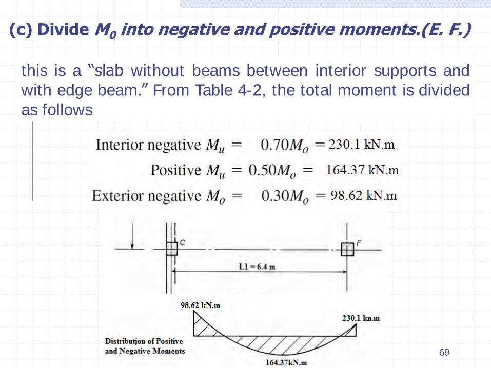
(c) Divide M0 into negative and positive moments.(E. F.)
this is a “slab without beams between interior supports and with edge beam.” From Table 4-2, the total moment is divided as follows
69

(d) Divide the moments between the column and middle strips.
Interior column-strip negative moment
Interior middle-strip negative moment
Positive moments: Table 4-4
70
Column strip positive moment = 0.60 x 164.37 =98.62 kN.m Middle strip positive moment = 164.37-98.62 =65.75 kN.m

71
Option a
Option b

C1 > C2, the larger of these two values is used; therefore, C = 2096.33 x 106 mm4.
Is is the moment of inertia of the strip of slab being designed, which has b =L2= 5.75 m and h = 200mm. Then
Exterior col.-strip (-) moment
Exterior M. S. (-) moment 72
=0.97 x 98.62 = 95.66 kN.m
= 98.62 – 95.66 = 2.96 kN.m

73

Transfer of Moments to Col.
Exterior Columns
The moment to be transferred from a slab to an edge col. is 0.3M0
Interior Columns
The total moment- transfer used in the design of the col. above and below the floor are based on an unbalanced moment resulting from an uneven distribution of LL.
qDu and qLu = the factored DL and LL on the longer span. q’Du = The factored DL on the shorter span adjacent to the col. l2 and ln = The longer of the adjacent spans.
74

Equivalent Frame Method (EFM)
For equivalent-frame methods, a stiffness analy sis of a slab–column frame is used to determine the longitudinal distribution of bending moments, including possible pattern loadings.
The classic equivalent-frame method assumed that moment distribution would be the calculation procedure used to analyze the continuous-slab system.
75

Elevation of the frame
Perspective view 76

Properties of Slab–Beams
77

78

79
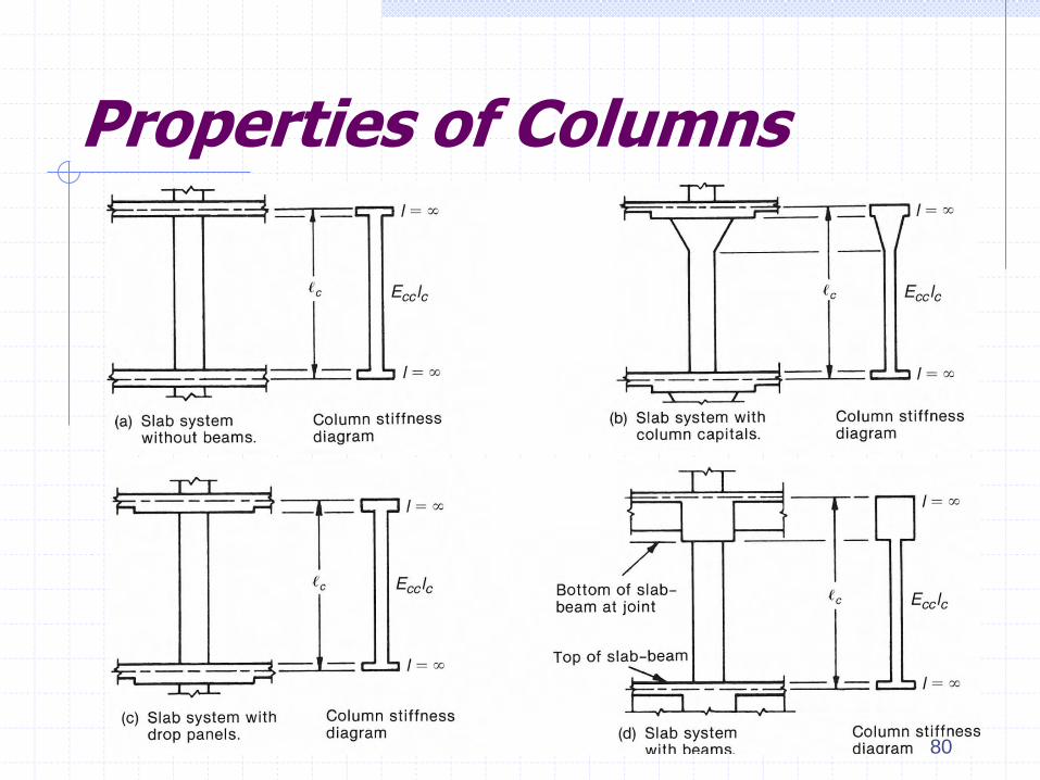
Properties of Columns
80

Torsional Members and Equivalent Columns
Frame action and twisting of edge member 81

The stiffness of the equivalent column Kec
ΣKc = the sum of the flexural stiffnesses of the columns above and below the slab
Kt = the torsional stiffness of the attached torsional members
82

If a beam parallel to the direction frames into the col., a major fraction of the exterior (-) moment is transferred directly to the col. without involving the attached torsional member.
In such a case, Kec underestimates the stiffness of the col. This is allowed for empirically by multiplying Kt by the ratio Isb/Is where Isb is the moment of inertia of the slab and beam together and Is is the moment of inertia of the slab neglecting the beam stem.
Torsional members
83

Shear Strength and ShearReinforcements in Two-Way Floor Slab System
1

SHEAR STRENGTH OF TWO-WAY SLABS
In the case of a two-way slab or footing, two way shear failure mechanisms are possible. One-way shear or beam-action shear involves an inclined crack extending across the entire width of the structure. Two-way she g shear involves a truncated cone or pyramid-shaped surface around the column.
2

Inclined cracks in a slab after a two way shear failure 3

Critical Sections for Punching Shear
Two-way shear is assumed to be critical on a vertical section through the slab or footing Extending a distance d/2 around the column faces.
4

Critical Sections for Slabs with Drop Panels
When high shear forces are being transferred at a slab-col. connection, the slab shear strength can be increased locally by using a drop panel to locally increase the thickness of the slab.
5

Critical Sections Near Holes and At Edges
6
When openings are located at a distance <10h from the column center, the critical section is reduced as shown.
For edge and corner columns, the critical sections are as shown.
h = slab thickness Ld= Development Length

7
Tributary Areas for Shear in Two-Way Slabs
The tributary areas (T. A.) used to calculate the direct shear Vu is bounded by lines of zero shear.
(a) For internal columns, these lines can be assumed to pass through the centers of the adjacent panels. (b) For edge columns, these lines are approximately at 0.42L to 0.45L from the centers of exterior columns. However, in order to consider the increased shear in the first internal support in the exterior panel, the tributary length is increased to 1.15 x (0.5L).

Tributary Areas for Shear in Two-Way Slabs
8

Design Equations: Two-Way Shear with Negligible Moment Transfer
n c sV V V
The basic equation for shear design states that:
Punching Shear, Vc Carried by Concrete in Two-Way Slabs
In slabs, designers prefer to avoid the use of shear reinforcement, the concrete is used to resist the whole shear stress, and thus, Vs is usually neglected.
9

The two-way shear strength (or the punching shear
strength) of concrete in slabs (& footings) Vc is taken as
the smallest of:
long side/short side of column, concentrated load
or reaction area
Perimeter of the critical section around the column
where, b =
b0 =
where as = 40 for interior columns = 30 for edge columns = 20 for corner columns 10
kN (1)
(2) kN
(3) kN

11
• In the first equation, the shear strength is assumed to be double of one way shear because there is shear in both directions.
• In the second equation, the distribution of shear stresses around the column is maximum at the corners.

12
For rectangular columns with longer sides >> shorter sides, the shear stress along the longer sides << that at the corners. This effect is considered by the value of b.
Note:

One-Way Shear in Slabs
where b is the width of the critical sections. One-way shear is seldom critical in flat plates
or flat slabs 13
Slabs should also be checked for one way shear. The critical section for O.W.S. occurs at a distance d: • From the face of the columns, or • From the face of the drop panels, or • From the face of the column heads.
The shear strength for one way shear:

14
One-Way Shear in Slabs

EX. 4.6 Checking One-Way and Two-Way Shear at an Interior Col. in a Flat Plate
A slab of 150mm thick and effective depth d=130mm. ACI states that the min. clear cover for slab to reinf. is 20mm. The slab supports: A uniform superimposed DL = 100 kg/m2 A uniform LL = 300 kg/m2. Use N.W. Concrete and fc = 21 MPa The moments transferred from slab to columns are negligible. It is required to check the shear capacity of an interior column.
15

16

1. Determine the factored uniform load.
2. Check the one-way shear. One-way shear is critical at a distance d from the face of the column. That is at sections A–A and B–B. Because the tributary area for section A–A is larger, this section will be more critical.
17
Wu =1.2 (0.15 x 2.5 + 0.1) +1.6 x 0.3 = 1.05 t/m2
= 10.5 kN/m2

18
(a) Compute Vu at section A-A
Vu = 10.5 x 2.47 x 5.5 = 142.64 kN
No shear reinforcement
One way shear is satisfactory

3. Check the two-way punching shear. Punching shear is critical on a rectangular section located at d/2 away from the face of the column
(a) Compute Vu on the critical section for two-way shear.
19
Vu =10.5 (5.5 x 5.5 – 0.43 x 0.78) = 314.1 kN

(b) Compute fVc for the critical section. The length of the critical perimeter is:
Now,Vc is to be taken as the smallest of the following
20
bo = 2 (430 + 780) = 2420 mm2
as = 40 for columns in the center of column

fVc > Vu =314.1 kN The slab is o.k. for two-way shear.
21

Increasing the Shear Strength of concrete for two way slabs
If Vu > fVc then, the shear capacity can be increased by any of the following four methods: 1. Thicken the slab over the entire panel.
(Note: this may be counterproductive because the weight of the slab may increase Vu significantly).
2. Use a drop panel to thicken the slab adjacent to
the column (i.e. increasing the effective depth, d, and the perimeter of the C. S.).
3. Increase b0 by increasing the column size or
by adding a fillet or shear capital around the col. 22

23
4. Add shear reinforcement.
The effect of each of these parameters is shown below:

Shear Reinforcement for Two-Way Slabs
(a) Stirrups
24
The ACI allows the use of shear reinforcement around the columns in the form:

b-Structural Steel Shear heads
Consists of steel I-beams or channel welded into four
cross arms to be placed in slab above a column. Does
not apply to external columns due to lateral loads and
torsion.
Shear heads at external columns require special
precautions to transfer the unbalanced moment.
This type of shear reinforcement is not usually used for
several reasons.
25
Shear Reinforcement for Two-Way Slabs

26

27
C-Headed Shear Studs
These act in a similar manner as hooked stirrups legs, but the heads of the shear studs provide better anchorage.
Headed shear studs consists of rows of vertical rods, each with circular head on the top end and welded flat steel plates at the bottom. The vertical rods are called headed shear reinforcement or headed shear studs The assembly of the studs and the flat plates is called Stud Rail.

28

d-Design of Shear Reinforcement
The following design requirements apply to stirrup-type reinforcement and headed shear-studs.
(a) The critical section for two-way shear is located at d/2 away from the face and corners of the column. We shall refer to this as the inner critical section. (b) A second peripheral line is located at d/2 outside the outermost set of stirrup legs or headed shear studs. This is referred to as the outer critical section.
29
Shear reinforcement is required when Vu(c.s) > fVc

• The nominal shear strength of a two-way slab with stirrup-type shear reinforcement
30
d-Design of Shear Reinforcement
With s ≤ d/2
The shear reinforcement should be extended to a point where the slab shear stress at the outer critical section becomes equal to the concrete shear strength.

31
• The nominal shear strength of a two-way slab with headed-type shear reinforcement
d-Design of Shear Reinforcement
Because the bearing stresses under the heads confine the slab around the column much more than the stirrups, the concrete shear strength of concrete is increased to:

EX. 4-7 Design an Interior Slab–Column Connection with Headed Shear Reinforcement
(Moment Transfer is neglected)
A 150 mm thick flat-plate slab with 14 mm flexural reinforcement is supported by 300 mm square columns spaced at 5.0 m on centers N–S and 5.5 m on centers E–W. The service dead loads on the slab DL =450 kg/m2 (including self-weight). The service live loads on the slab LL =500 kg/m2 Concrete fc = 27.6 MPa. Check the capacity of an interior slab–col. connection. If necessary, design shear reinforcement using headed shear studs
32

33

1. Critical section for two-way shear around the col. At this stage of the calculations, the designer does not know whether shear reinf. will be required. We will assume it is not and will redo the calculations if we are wrong. Assuming 14 mm flexural reinf.
The inner critical shear section for two-way shear in a flat plate extends around the col. at d/2 = 61.5mm from the face of the col.
The area of the c. s. =(c1+d)(c2+d)= (300+123)2
=178929 mm2
34
Effective depth of the section d = 150-20-14/2 = 123 mm
The perimeter of the C. S. bo =2[(c1+d)+(c2+d)] =2[(300+123)+(300+123)] = 1692 mm

2. Compute the shear acting on the critical shear section.
The factored shear force on the C. S. is
For slabs without shear reinforcement,
35
Wu =1.2 DL + 1.6 LL = 1.2(0.45) +1.6(0.5) = 1.34 t/m2 = 13.4 kN/m2
Vu = Wu [L1.L2 – (c1+d)2] =13.4 [5 x5.5 – 0.178929] = 366.102 kN

36
Thus, shear reinf. is required at the critical shear section.
The slab - column connection is not safe

Using shear studs as shear reinforcement results in
The max. value of fVn allowed with headed-shear studs is
Then, the slab depth and column dimensions are satisfactory.
37
> Vu = 366.102 kN

3. Distribution of punching shear reinforcement. Use rows of shear studs welded to bars parallel and perpendicular to the main slab reinforcement. Using a trial and error process:
Try eight stud rails, each with four 10mm diameter studs (Ab=78.53mm2) with 30mm diameter heads, and fyt = 414 MPa
Before proceeding to layout the subsequent rows of shear studs, the shear strength should be checked at the inner critical section. The spacing of the first set of shear studs is d/2. The area provided by the inner row of shear studs is
38
Av = 78.53 x 8 =628.24 mm2
Vs.prov = Av fyt = 628.28 x 414 = 260 kN >Vs.req=91.12 kN

39
Thus, the stud diameters and spacing are satisfactory.
vumax =

Try 8 stud rails with the first stud located at s0 = 60mm from the column face. Subsequent studs are at a spacing of s = 90 mm with four 10mm-diameter headed shear studs per rail.
The external studs are at 60 +90x3 =330 mm from the face of the column, and the outer critical section is (330+d/2) = 391.5mm from the face of the column. The perimeter of this peripheral line is
40

41

4. Check the shear stresses on the outer critical section. The factored shear force on the concrete at the outer critical section is
The shear stress on the outer critical section is limited to:
42
Vu =13.4 [5.5 x 5 – 0.866344] = 356.89 kN

43
Try seven studs per rail, the distance from the outer face of the O. C. S. to the column face =[60+6x90 + d/2] = 660 mm Perimeter bo = 660 √2 x 4 + 300 x 4 = 4933.52 mm Area inside the O. C. S. =4 x 6602/2 +660 x 300 x 4 + 300 x 300 = 1.7532 m2
Vu =13.4 [5.5 x 5 – 1.7532] = 345 kN

44
Therefore, use 8 stud rails, with seven 10mm diameter headed shear studs.
• First one at 60 mm • Other 6 at 90 mm Starting from the face of the column.

45
COMBINED SHEAR AND MOMENT TRANSFER IN TWO-WAY SLABS
(a) Slab – Column Connections
Gravity loads or/and lateral loads cause unbalanced moment over the support. This moment is transferred to the columns above and below the slab through the slab area around the column. Its behavior is complex and involves flexure, two way shear and torsion in the slab area attached to the column.

COMBINED SHEAR AND MOMENT TRANSFER IN TWO-WAY SLABS
46 Shear stresses due to shear and moment transfer for Internal columns

COMBINED SHEAR AND MOMENT TRANSFER IN TWO-WAY SLABS
47 Shear stresses due to shear and moment transfer for Edge columns

ACI Commentary Design Method (Jc Method)
The max. shear stress on the critical section surrounding the column for slab–column connections transferring both shear and moment is given by
b0 = is the length of the critical shear perimeter. d = is the effective slab depth. Jc = an effective polar moment of inertia for the
critical shear section. bod = Area of the critical shear section
48

Vu = is the factored shear being transferred from the slab to the column, and it is assumed to act through the centroid of the critical section for shear.
Mu = is the factored moment being transferred at the connection or unbalanced moment.
c = is the distance between the center of the critical section (C. S.) and the edge of the C. S. where the stress, vu is being calculated.
gv = is the fraction of the moment Mu transferred by shear stresses on the critical section.
gf = is the fraction of the moment Mu transferred by direct flexure.
49

ACI 13.5.3.2 defines the fraction of the moment transferred by flexure, as
b1 = Dimension of the critical section in the direction of the strip under consideration.
b2 = Dimension of the critical section in the direction perpendicular to the strip under consideration.
50
b2=c2+d
b1=c1+d
c1
c2 c2
c1
b2=c2+d
b1=c1+d/2
Direction of moment
Internal columns Edge columns
c
c
c. s. c. s.

51
C1 = Dimension of the column in the direction of strip under consideration. C2 = Dimension of the column in the direction perpendicular to strip under consideration.
• For slabs without shear reinforcement, The maximum shear stress due to direct shear and torsion
Then, the connection is safe
• The moment transferred by flexure
Mf = gf Mu is distributed over a width = c2 + 2 (1.5 h)
h = the slab thickness

Sufficient slab reinforcement will need to be provided within a transfer width to carry the fraction of the transfer moment, gf Mu
52
Direction of moment

53
Note: • For square internal columns, c1=c2 and b1=b2
gf = 0.6 and gv = 0.40 • For a slab attached to the side of a wall
gf = 1.0 and gv = 0 • For a slab attached to the end of a long wall
gf = 0 and gv = 1
Slab attached to the side of a long wall
b1
b2
b1/b2 <<
gf = 1.0 and gv = 0
Direction of moment
b1
b2
slab attached to the end of a long wall
b1/b2 >>
gf = 0 and gv = 1

54
• ACI 13.5.3.3 allows the designer to increase gf : (i) To 1.0 if the factored shear, Vu <0.75fVc (ii) To 1.0 at corner connections when Vu <0.5 fVc. (iii) By 25 % at interior connections when Vu <0.4 fVc

55
Properties of the Critical Section Polar Moment of Inertia, Jc
To calculate the polar moment of inertia Jc , the critical section is broken into: • 4 rectangles for internal columns, • 3 rectangles for edge columns, and • 2 rectangles for corner columns.
Each face of the critical section is a rectangle,
Jc of this rectangle about axis z–z, which is perpendicular to the plane of the rectangle and displaced a distance x from the centroid of the rectangle is given by:

56
Polar Moment of Inertia, Jc
(i) Internal columns The center of the C. S. is at the center of the column.
b2=c2+d
b1=c1+d
c2
Direction of moment
Internal columns
c
c1 c. s.
A
B C
D
x

(a) Moments about an axis parallel to the edge (axis z–z). OR Moment direction to the edge
57
(ii) Edge columns
Polar Moment of Inertia, Jc
c2 b2=c2+d
b1=c1+d/2
Edge columns
CAB
c. s.
Direction of moment
c1
Z
A
B C
D

58
The position of the center of the C. S. is:
Polar Moment of Inertia, Jc

(b) Moments about an axis perpendicular to the edge (axis w–w). OR Moment direction // to the edge
59
Polar Moment of Inertia, Jc
c2 b2=c2+d
b1=c1+d/2
Edge columns
CAB
c. s.
Direct
ion o
f m
om
ent
c1
Z
A
B C
D
w
The position of the center of the C. S. is c b1/2
60
Polar Moment of Inertia, Jc
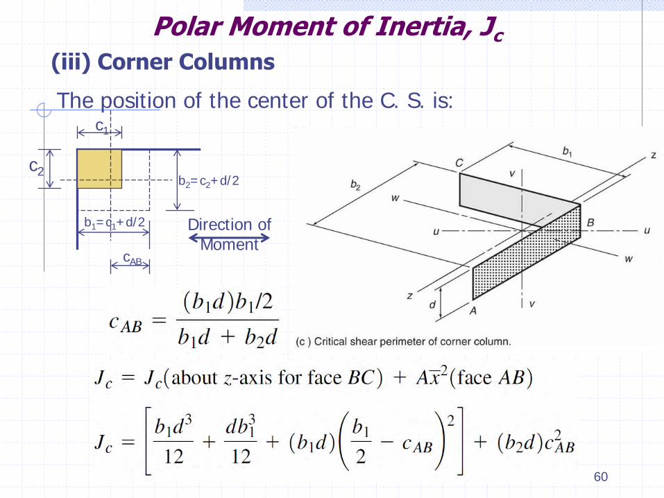
(iii) Corner Columns
The position of the center of the C. S. is: c1
c2
b1=c1+d/2
b2=c2+d/2
cAB
Direction of Moment

Circular Columns
61
Polar Moment of Inertia, Jc

62
Polar Moment of Inertia, Jc
For simplicity, the polar moment of inertia Jc can be obtained from the figure below:

63

Load Patterns for Max. Shear Stress Due to Combined Shear and Moment Transfer
64

65
Load Patterns for Max. Shear Stress Due to Combined Shear and Moment Transfer
L1 L’’1 L’1 L’’’1
L1/2 L’1/2
wmax Vu
Vu
Mu =0
Vu1 Vu2
wmax wmin
Vu
Mu
L’’1/2 L’’’1/2
Vu = Vu1 + Vu2
Mu=Mu1-Mu2+(Vu1-Vu2)c1/2
Case i Case ii
Direction of moment
Mu2 Mu1

66
(b) For Edge Columns. Case 1: Moment direction to the edge of the slab The critical loading for max. shear stress occurs with full- factored DL and LL acting simultaneously on both edge panels adjoining the column. This will produce the max. shear force and max. transfer moment.
Load Patterns for Max. Shear Stress Due to Combined Shear and Moment Transfer
L1/2
wmax
Vu1
wmax
L1
Vu
Direction of moment
Mu1
Vu = Vu1 Mu=Mu1+Vu1 (c-d/2)

67
Case 2: Moment direction // to the edge of the slab Two cases may need to be considered: (i) Full-factored DL and LL should be applied to both adjacent panels. This case will produce the max. shear
force, but a smaller transfer moment if the consecutive
spans are equals.
Load Patterns for Max. Shear Stress Due to Combined Shear and Moment Transfer

(ii) Max. full-factored loads should be applied only to the longer panel and minimum loads on the shorter panel. This case will produce a larger transfer moment, but a lower shear force.
68
Load Patterns for Max. Shear Stress Due to Combined Shear and Moment Transfer
L1/2
wmax
Vu1
wmin
Dir
ecti
on
of
mo
me
nt
Mu1
L1
Vu2
Vu
Mu2
Mu
Vu = Vu1 + Vu2 Mu=Mu1 – Mu2+ (Vu1 - Vu2) c2/2
69
(c) For corner columns. The maximum shear stress normally occurs due to the load case where full-factored dead and live load are applied to all panels of the floor system.
Load Patterns for Max. Shear Stress Due to Combined Shear and Moment Transfer

70
Moment Transfer on both principal directions
However, due to unusual span lengths and column layouts, it may be appropriate to check the maximum shear stress due to moments acting simultaneously about both principal axes. That is:

71
Where: Vu, Mu1 and Mu2 are the shear force and moments about the two principal axes for a consistent load case. Jc1 and Jc2 are the polar moment of inertias of the critical section about the two principal axes. C and C’ are the positions of the center of the C. S. about the two principal axes.
This procedure would produce a max. shear stress at a point while the ACI code requirements refer to a stress over a defined area.
Mu1
Mu2
Max. stress

72
However, in order to take the effect of point stress on the critical section, the ACI code allows an overstress of 15 % increase in the shear strength of concrete.

Alternative Analysis of Max. Shear Stress Due to Combined Shear and Moment Transfer at Exterior Connections
The max. shear stress on a crictical section at the front face of an exterior col. resulting from transfer of shear plus moment acting about an axis parallel to the edge of the slab.
Vu = is the factored shear to be transferred. Mu, face = is the factored moment at the face of the col. d = the effective depth of the slab. c1 , c2 = the column dimensions perpendicular and parallel to
the edge of the slab. 73

Ex. 4-8 Checking Combined Shear and Moment Transfer at an Edge Col.
A 300 x 400 mm col. is located 100mm from the edge of a flat plate without edge beams. The slab is 160mm thick, with an effective depth d=135mm. The direct-design method gives: -The moment at the edge panel, Mo = 206 kN.m -The shear from the edge panel Vu =140 kN. -The portion of the slab outside the centerline of the col. produces a factored shear force of 18 kN acting at 150mm outside the center of the col. -The loading that causes moment perpendicular to the edge is more critical than the other direction fc = 24 MPa and the fy = 414 MPa
74

75

1. Locate the critical shear perimeter. The critical shear perimeter is located at d/2 from the sides of the column. Because the edge of the slab is located at
a distance < 4h away
from the outside face of the column, a perimeter similar to that shown is assumed to be critical. 76

2. determine the centroid of the critical shear section
77
CAB = 148.67 mm CCD = 318.82 mm

Moment transferred to the edge col = 26% Mo (Table 4-2) Moment transferred applied at the centroid of the C. S.
The total shear to be transferred is
78
3. Compute the moment about the centroid of the C. S.
M-v = 0.26 (206) = 53.56 kN.m
Total moment at the centroid of the C. S.
M-v = 53.56 – 18 (0.218) = 49.636 kN.m
Vu = 140 + 18 = 158 kN

Eq. (2):
Eq. (3):
4. Compute fVc and Vu / fVc. Vc is the smallest value of:
79
bo = 2b1 + b2 = 1470 mm
Eq. (1):

5. Determine the moment transferred by flexure, gf
ACI Code Section 13.5.3.3 allows gf to be increased up to 1.0 if vu /fvc <0.75 at an exterior column. From step 4, vu /fvc = 0.650. Therefore, try gf equal to 1.0 and check the reinf. needed. Mf = 1 X 49.63 = 49.63 kN.m
80

6. Design the reinf. for moment transfer by flexure.
Try 6 Φ 16 mm /0.88m = 1206 mm2
81
Effective width for flexure = c2 + 2(1.5h) = 400 + 2(1.5 X 160)=880 mm
Mf = Φ As fy (d-a/2), Assume (d-a/2) = 0.95 d, Φ=0.90
49.63 X 106 = 0.90 As (414)(0.95 X 135) As = 1038.58 mm2 / 0.88 m
O. K.

The moment transferred by eccentric shear stress is,
82

7. Compute the polar moment of inertia, Jc
8. Compute the shear stresses.
83
= 0.696 ± 0.559

9. Check accuracy of approximate method.
Assume from step 6 can be used for Mu,face
This is approximately 10% higher than the stress calculated on face AB in step 8. For a quick design check of the slab thickness, this certainly would be accurate enough.
85

Because fvc≈vu the shear is o.k. Use a 300 x 400 mm col., with 6 Φ 16 mm / 0.88 m (at 145mm on centers, centered on the column).
84
The shear stress on face AB, vu = 0.696 + 0.559 = 1.255 MPa The shear stress on face CD, vu = 0.696 - 0.559 = 0.137 MPa From step 4, Φvc = 1.224 MPa

Drop panels-Drop or Shear caps in Two-Way Floor Slabsand Applications
1

Drop Panels
They are provided for 3 main reasons: 1. The minimum thickness of slab required to limit
deflections may be reduced by 10% if the slab has drop panels conforming to ACI 13.2.5. The drop panel stiffens the slab in the region of highest moments and hence reduces the deflection.
2

2. By increasing the overall depth of the slab, the lever arm, d-a/2, used in computing the area of steel is increased, resulting in less required reinf. in this region.
3. A drop panel gives additional slab depth at the col., thereby increasing the area of the critical shear perimeter.
Drop Panels
3

Column Capitals (Column Heads)
This is done to provide a larger perimeter of the critical section (C. S.) at the column and to reduce the clear span, ln used in computing moments.
As a result, the floor forming becomes considerably more complicated and expensive.
4

Shear Caps
Shear caps are a projection below the slab, similar to a drop panel, but they do not necessarily satisfy the dimensional limits given in ACI 13.2.5.
Shear caps are used to increase the shear strength at a slab–column connection by locally increasing the effective depth of the slab. 5
H≥V with V= (50% to 100%) h

6
Reinforcement
• In a flat plate or flat slab, the moments are larger in the slab strips spanning in the long direction of the panels. Then, reinforcement for the long span is placed closer to the top and bottom of the slab than the reinforcement in the short spans.
• For slabs supported on beams having gam.f >1,
the reinforcement pattern should be reversed.

7
Cover and Effective Depth The ACI code specifies the minimum clear cover to the face of the steel reinforcement in slabs as follows: • Cover Cmin = 20 mm, for No.36 and smaller For slabs not exposed to earth or weather. • Cover Cmin = 40 mm, for No.36 and smaller Cover Cmin = 50 mm, for No.19 and larger For slabs exposed to earth or weather. • Cover Cmin > 50 mm, for concrete slabs exposed to
deicing salts such as parking decks). In this case, the use of coated bars is recommended.

Cover and Effective Depth In two way slabs, reinforcement are paced in two layers: • For spans ≤ 7.5 m, a bar diameter ≤16mm is required. • For spans > 7.5 m, a bar diameter = 22mm is required.
• The effective depth, d, of flat plates or flat slabs can be considered as follows:
d = h-20mm-0.5Φb, for the long span, d = h-20mm-1.5Φb, for the short span • However, for preliminary design, the effective depth, d,
can be considered as:
-For Flat-plates or flat-slabs with spans ≤7.5 m d≈ h – 27 mm for long spans d≈ h – 45 mm for short spans
8

9
-For Flat-plates or flat-slabs with spans >7.5 m d≈ h – 30 mm for long spans d≈ h – 50 mm for short spans

Spacing Requirements, Minimum Reinforcement and bar size
Maximum Spacing of Reinforcement
At points of max. +/- M:
Spacing S as defined for crack control and ≤ 450mm at any location
Minimum Reinforcement Requirements Asmin= 0.0020bh for steel Grade-40 or -50 deformed bars (fy = 275 MPa or 350 MPa) = 0.0018bh for steel Grade-60 deformed bars (fy = 4 20 MPa)
10
Steel bar size Φb ≥ 1 3 mm at 30 cm centers

Min. cut-off points for slabs without beams (Details of steel Reinforcement)
11

12
Note: • Where adjacent spans have unequal lengths, the
extension of the negative moment steel bars past the face of the support is based on the length of the larger span.
• When the DDM method is not used, the tensile steel reinforcement should be detailed according the development length Ld and the anchorage length La.
• All negative moment steel reinforcement to the edge
of the slab should be: bent, hooked or anchored to spandrel beams, columns, and walls in order to provide enough development length.
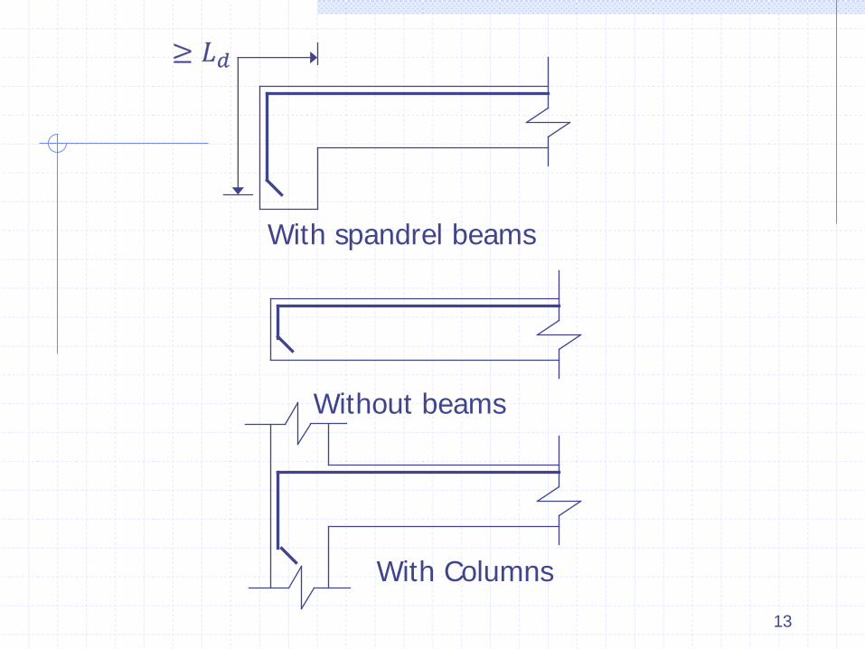
13
With spandrel beams
Without beams
With Columns

14
Details of Slab reinforcement at an edge column

15
C2
Ct C1
Edge of the slab
• Equivalent torsion reinforcement, should be provided along the edge of the slab with the dimensions defined above and extending a distance at least 2h away from the face of the column.

EX. 4-9 Design of a Flat-Plate Floor without Spandrel Beams—DDM
A flat-plate floor supports its own DL, + 125 kg/m2 for partitions + finishes, and a LL of 250 kg/m2. The slab extends 100 mm past the exterior face of the col. to support an exterior wall of weight 450 kg/m of length of the wall.
Story height is 2.8m. fc = 27.6 MPa and f y = 414 MPa. Select the thickness,
compute the moments, and select the reinf. in the slab.
16

To design the slab, it is necessary to consider: • Two east–west strips (Fig. a), and • Two north–south strips (Fig. b).
17
Solution
Figure a

18

Therefore, use the direct-design method. 19

2. Select the thickness. (a) Slab thickness for deflections control.
Panel 1–2–A–B (corner panel; exterior):
Panel 1–2–B–C (exterior):
Panel 2–3–A–B (exterior); same as 1-2-A-B.
Panel 2–3–B–C (interior)
20
Clear span Ln = 5.5 – (0.3/2 + 0.5/2) =5.1 m Minimum h = Ln/30 = 5100/30 = 170 mm
Clear span Ln = 6 – (0.5/2 + 0.5/2) =5.5 m Minimum h = Ln/30 = 5500/30 = 183 mm
Ln =5.5 m, hmin = Ln/33 = 166 mm

(b) Check the thickness for shear. Check at col. B2 and B1.
21
Try h = 200 mm
Column B1
• The maximum moment about the E-F axis occurs when the area EFGH is all loaded with live loads.
• The maximum moment about the B-B axis occurs when
live loads are on one side of the column line B-B.
Assume the tributary area extends 0.5 L from the centers of the edge or corner columns.

22
Initial critical shear perimeters and tributary areas for col. B1 and B2
x1.15 x1.15
x1.15
External panels
x1.15
Internal panels

23
Tributary Area for Slab Strip A
Span A2-A3
Span A1-A2

24
Tributary Area for Slab Strip B Span B1-B2
Span B2-B3

Column B2: Internal Column
25
Ultimate Load: Wu =1.2 WDL + 1.6 WLL
= 1.2 [0.2 x2.5 + 0.125] 1.6 (0.25) = 1.15 t/m2
Wu =1.4 WDL = 0.875 t/m2 (does not control)
Therefore, Wu = 1.15 t/m2 = 11.5 kN/m2
Assume effective depth d = 200-30 = 170 mm
The critical section for an internal column b1 = C1 + d = 500 + 170 = 670 mm b2 = C2 + d = 300 + 170 = 470 mm
Perimeter of the C. S: bo = 2(b1 + b2) = 2(470+670) = 2280 mm

26
Shear Area = bo.d= 387600 mm2
Ultimate Shear force Vu = Wu (L1L2- b1b2) Vu = 11.5[(2.75 x 1.15 +3)(2.4 x 1.15 + 2.4) – 0.67 x 0.47] = 362 kN
Shear strength of concrete
Therefore, Vc = 678.76 kN

27
Vn = Vu/Φ = 362/0.75 = 482.74 kN < Vc
Note:

Column B1: Edge Column
28
670
485 The critical section for an internal column b2 = C2 + d = 500 + 170 = 670 mm b1 = C1 + d/2 + 100 =300+170/2 + 100 = 470 mm
Perimeter of the C. S: bo = 2b1 + b2 = 1640 mm
Shear Area = bo.d= 278800 mm2
Ultimate Shear force Vu = Wu (L1L2- b1b2) Vu = 11.5[(2.75 x 1.15 +3)(2.4 + 0.25) – 0.67 x 0.485] +[0.45 x 1.2 (5.5/2 +6/2)]= 188.165 kN

29
Shear strength of concrete
Therefore, Vc = 488.23 kN
Vn = Vu/Φ = 188.15/0.75 = 250.88 kN < Vc

30
(3) Compute the moments in a slab strip along column line 2. Because there are no edge beams, af = 0 In this strip, slab panels A2-B2 and C2-D2 are end panels B2-C2 is an interior panels
Note:

31

Line 8.
Line 6. The moment in the exterior panels is divided by using Table 4-2:
32
The ACI requires that interior columns be designed for moment:
= 0.07[(1.2 x 0.625 + 0.5 x 1.6 x 0.25) 4.8 x 5.52
– (1.2 x 0.625) 4.8 x 5.12] = 44.3 kN.m
This moment is to be distributed between the lower and upper columns in the ratio of their stiffness.

33
Note;
(a) At interior columns, design the slab at the joint for the larger negative moment.
(c) The unbalanced moment at the exterior edge 46.67 kN.m is divided between the lower and upper columns in the ratio of their stiffness. The moment due to the wall load acting at the edge of the slab may counterbalance the moment transferred from the slab to columns, but this moment was neglected in this example.

34
4 – Moment in the slab strip along column line 1

35

Line 8. The interior col. (B1 and C1) are designed for the moment from the slab given by:
Line 9. The factored DL of the wall is 1.2×0.45 = 0.54 t/m = 5.4 kN/m
Line 10. The total static moment of the wall load is Therefore,
36
= 0.07[(1.2 x 0.625 + 0.5 x 1.6 x 0.25) 2.65 x 5.52
– (1.2 x 0.625) 2.65 x 5.12] = 17.12 kN.m
In span A1–B1,
In span B1–C1,

37
5- Distribution of Moments to column and Middle Strips- Strips 1 and 2
Strips 1 and 2 are horizontal strips along axis 1 and 2.
(a) Divide the slab strip into Middle and column strips. The column strip extends Lmin/4 from the center of the column. Column strip width = 2.4 m Along line 2 middle strip width = 2.4 m
Along line 1 ½ Column strip width = 1.45 m
½ Middle strip width = 1.2 m

38

39

40

41

42 Details of Reinforcement in the horizontal Direction

43 Details of Reinforcement in the Vertical Direction

9. Check the shear at the exterior columns for combined shear and moment transfer.
Check the shear at column B1
(a) Locate the critical shear perimeter.
44
The effective depth d = 170 mm
b1=C1+d/2 =(300+100)+170/2=485 b2= C2+d 500+170=670mm
Critical section- Col. B1

(b) Locate the centroid of the shear perimeter. For moments about the AB axis,
Moments about the w–w axis,
45
CAB = 143.43 mm, CCD = 485-143.43 =341.57 mm
CCB = CAD = b2/2 =335 mm
Critical section- Col. B1

(c) Compute the shear and the moment about the centroid of the shear perimeter. As calculated in step 2(b), Vu = 188.165 kN
Moment transferred from the slab to the column is given in the table (end moment) = 41.60 kN.m
46
Note:
• The moment from the short slab cantilever is neglected (Safe side). However, if the cantilever span is long and the wall is heavy, then this can be considered.
• Moments about axis w–w come from the slab strips parallel to the edge. In the Table in strip 1, line 8 gives the moment transferred to the column when one adjacent panel is loaded with half live load and the other panel is not.

47
In summary, B1 must be designed for: Vu = 188.165 kN and Mzz = 41.6 kN.m
and Mww = 6.5 kN.m.
• Because, the critical shear check normally involves the shear due to all the panels loaded, we will use the moments from line 7.
From line 12 (table), we find that the unbalanced moment due to the wall load
Munb = 0.97 kN.m
From line 7, slab strip 1 in the table, Munb = 74.9-69.37 = 5.53 kN.m
The total moment to be transferred is Munb = 5.53 + 0.97= 6.5 kN.m

(d) Det the fraction of the moment transferred by flexure, gf . Moments about the z–z axis:
Moments about the w–w axis: Exchanging b1 and b2, gives gf2 = 0.561. ACI 13.5.3.3 allows gf to be increased by up to 25% if Vu /fVc <0.4. Thus, no increase can be made in gf2. Moment transferred by flexure is
48 Mf2 = gf2 Mww = 0.561 x 6.5=3.64 kN.m

(e) Design the reinforcement required for moment transfer by flexure. Moments about the z–z axis:
• Width effective for flexure:
Effective width
Effective width
• The steel in step 8 in the vertical col. Strip over B1 is 7 Φ 14 mm =1077 mm2 in a col.-strip width=2.4 m. or with a spacing S=2400/7 = 340 mm
49
W =c2 + 2(1.5h)=500+2(1.5x200)=1100mm
W=c2 + 2ct = 500 + 2(300)= 1100mm
= 1100 mm
• Steel Reinforcement

50
• Because, the computed As was based on (d-a/2)=0.95d Check As

51
< As Prov. OK

52
The moment transferred by flexure Mf2=3.64 kN.m This is a very small moment
• The steel provided in step 8 in the horizontal column strip over B1 is 8 Φ 14 mm = 1251.2 mm2 in an edge column strip width = 1.45 m.
Or with a spacing S = 1450/8=181 mm The No. of bars provided inside W = 700 mm is 700/181= 4 bars which are satisfactory to resist Mf2=3.64 kN.m
Moments about the w–w axis: • Effective width for moment transfer by flexure: W=C2+Lc+1.5h; Lc<1.5h =300+100+1.5(200)=700mm.

(f) Compute the shear stresses (about axis w-w).
The maximum stresses along sides CB and AD are
53
bo=2b1+b2=2x485+670=1640mm gv2 =1- gf2 =1-0.56=0.44
=23.041 x 109 mm4

Because there is no shear reinforcement in the slab, , where, from step 2(b),
Because , the shear is o.k. in this column–slab connection.
10. Check the shear at an interior col. for combined shear and moment transfer. Check the shear at column B2.
(a) Locate the critical shear perimeter.
54
Vc = 488.231 kN
b1=c1+d=300+170= 470mm
b2=c2+d=500+170= 670mm

(b) Locate the centroid of the Critical section. Because it is an internal column, the centroidal axes pass through the centers of the sides.
(c) Compute the forces to be transferred.
From step 2(b), Vu = 362.06 kN • Horizontal strip along line 2, line 7 in the Table , the
difference between the (-) moments on the two sides of column B2 is: Munb,yy=135.6-125.65= 9.95 kN.m
• Horizontal strip along line 2, line 7 in the Table , the difference between the (-) moments on the two sides of column B2 is: Munb,yy=135.6-125.65= 9.95 kN.m
55
bo=2(b1+b2)=2(470+670)= 2280mm

56
ACI allows gf to be increased by up to 25% if Vu /fVc < 0.4.
As shown in step 2(b), Vu /fVc = 0.741< 0.4, then, gf can’t be increased about either axis.
(d) Compute the fraction of the moment transferred by flexure.
gf1 (about x-x axis), b1 = 470mm, b2 = 670 mm
gf1 =o.641
gf2 (about y-y axis), b1 = 670mm, b2 = 470 mm
gf2 =o.512

(e) Compute the torsional moment of inertia, Jc
• Bending about y–y , Horizontal strip
(f) Design the reinf. for moment transfer. By inspection, the reinforcement already provided in the slab in both directions are adequate.
57
• Bending about x–x , Vertical strip
b1 = 470 mm b2 = 670 mm
Jc1 = 15.9 x 109 mm4
b1 = 670 mm b2 = 470 mm
Jc2 = 27.003 x 109 mm4

(g) Compute the shear stresses
The combined shear stress calculation, assumes bending about one principal axis at a time and thus the calculation of a maximum shear stress along one edge of the critical section. In this case, it is not clear which moment will cause the largest combined shear stress, so both will be calculated to determine which one is critical.
58
• For bending about axis x–x, Vertical strip
Mu1 = gv1 Muxx ; gv1 =1- gf1 =1-0.641=0.36 ; Muxx =8 kN.m = 0.36 (8) = 2.88 kN.m

• For bending about axis y–y, Horizontal strip
59
Mu2 = gv2 Muyy ; gv2 =1- gf2 =1-0.512=0.488 ; Muyy =9.95 kN.m

11. Check the shear at the corner col. (column A1) From the Tables, strip 1 and strip A indicate that moments at the corner column A1 are:
Two-Way Shear
(a) Locate the critical perimeter.
(b) Locate the centroid of the perimeter.
60
Muxx = 25.11 kN.m, Muyy = 30.27 kN.m
X X
Y
Two way shear
b1=b2= 485 mm
Cx =Cy =121.25mm

(c) Compute the forces to be transferred.
61
• Direct Shear Stress
Vu = 11.5 (3 x 2.65 – 0.485 x 0.485) = 88.72 kN
Shear due to wall load = [(3+2.65)-2(0.485)] x 0.45 x 1.2= 25.27 kN
Total Shear = 88.72+25.27 = 114 kN
• Unbalanced Moment
-For strip 1 (horizontal direction) Mu=30.27 kN.m
-For strip A (Vertical direction) Mu=25.11 kN.m

(d) Determine the fraction of the moment transferred by flexure.
The ACI allows gf to be increased to 1.0, provided that Vu /fVc <0.5 in the strip of slab and ρ < 0.375 ρb . In this case, the transfer width = 100 + 300 + 1.5 × 200 = 700 mm Perimeter bo = b1 + b2 = 2 (485) =970 mm
Shear strength of concrete:
62
b1 = b2 = 485 mm

(e) Design the reinf. for moment transfer by flexure. For strip 1; Mf1=0.6(30.27)= 18.162 kN.m Over a width For strip A; MfA=0.6(25.11)= 15.066 kN.m W W= 300 + 100 + 1.5(200) = 700 mm
63
Reinforcement can be calculated similar to edge column

(f) Compute the torsional moment of inertia, Jc
(g) Compute the shear stresses. ACI eccentric shear stress eqs were developed for bending about only one principal axis. However, for a corner col. we may want to consider simultaneous bending about both principal axes.
64

65
Since it is a square column, and critical section.
gv1 = gv2 = 0.60 ; c1 = c2 = 121.25 mm Jc1 = Jc2 = 4.238 x 109 mm4

66
One-Way Shear
(a) Locate the critical section
1040
1040
(b) Compute the shear at the critical section
• Shear due to slab Vu = 11.5 [(3 x 2.65) – 0.5 x 1.042]= 85.20 kN • Shear due to wall Vu = [(3 – 1.04) + (2.65 -1.04)] x 1.2 x 0.45 = 17.04 kN • Total shear = 85.2 + 17.04 = 102.24 kN

67

DESIGN OF SLABS WITH BEAMS IN TWO DIRECTIONS
The greater stiffness of the beams reduces the overall deflections, allowing a thinner slab to be used than in the case of a flat plate.
An advantage of slabs with beams in two directions lies in their reduced weight.
Two-way shear does not govern for most two-way slabs with beams, again allowing thinner slabs. This is offset by the increased overall depth of the floor system and increased forming and reinf-placing costs.
The direct-design method for computing moments in the slab and beams is the same as the procedure used in slabs without beams, with one additional step.
68

DESIGN OF SLABS WITH BEAMS IN TWO DIRECTIONS
1. Compute M0
2. Divide M0 between the + and - moment regions.
3. Divide the + and - moments between the col. and middle strips.
The additional step needed is 4. Divide the column-strip moments between
the beam and the slab.
69

If the beams have af1l2/l1, between 0 and 1.0, the shear forces computed from these tributary areas are multiplied by af1l2/l1.
When slabs are supported on beams having af1l2/l1>1, the beams must be designed for shear forces computed by assuming tributary areas bounded by 45º lines at the corners of the panels and the centerlines of the panels.
Tributary areas for computing shear in beams supporting two-way slabs 70
Distribution of shear between slab Column Strips and beams
F

71
Distribution of shear between slab Column Strips and beams
Beam Shear Force
F
1 0

Design of a Two-Way Slab with Beams in Both Directions—DDM
A floor supports its own weight, SDL of 25 kg/m2 for ceiling + 125 kg/m2 for future partitions + LL of 400 kg/m2. The exterior wall weights 450 kg/m and is supported by an edge beam. Design the horizontal strips of slab along column lines A and B, using fc = 27.6 MPa and fy = 414 MPa.
72

1. Select the design method, load, and resistance factors
73
• More than 3 panels in each direction. O.K • Max. difference of successive spans < 1/3. O.K • Ratio of L1/L2 < 2. O.K • Columns offset < 10 %. O.K • All loads are uniformly distributed loads. O.K • Service live load < 2 x service dead load. To be
checked.
• So use the DDM
Consider all beams have the same b and h.

74
2. Select the slab thickness and beam dimensions.
If there were only edge beams, the min. slab thickness for deflection would be governed by Table 13-1 and would be ln/33=206 mm based on ln = 6.8 m.
To select a thickness for a slab with beams between interior columns, the thickness will be arbitrarily reduced by 15% to account for the stiffening effect of the beams, giving a trial thickness of 175 mm.
Assume a beam with an overall depth of about 2.5 times that of the slab to give a value of af > 1.0. For the first trial, select a slab thickness of 175 mm and a beam 450mm wide by 450mm deep.

The cross sections of the beams are shown below.
75
Check the slab thickness

76

77

78
The slab thickness is the largest value, hs = 175 mm is O.K

Before continuing, check whether the shears at the column with the largest tributary area would put excessive shear forces into the beams at that column:
Ignoring the weight of the beam and assuming that the value of d is (450 - 60) = 390 mm Then,
fVc for the four beams is
Thus, (for two way shear) which will not be excessive if stirrups are used. Then, the beam dimensions are satisfactory. 79
Wu = 1.2 x (0.175 x 2.5 + 0.125 + 0.025) + 1.6 x 0.4 = 13.45 kN/m2
Vu = 13,45 [7.3 x 7.3 –(0.45 +0.39)2] = 707.26 kN

3. Compute the moments in the slab strip along col. line B
80

For the structural analysis, the unfactored DL and LL acting on the slab beam are:
81

82

83

84

85

9. Design the beams. The beams must be designed for moment, shear, and bar anchorage
86