Embed Size (px)
Citation preview

www.woodgroupodl.com
Dimensional Control Survey Team
“Zero Failures to Fit”
Presented by
Stewart Buchanan Global Head of Sales & Marketing

2 www.woodgroupodl.com
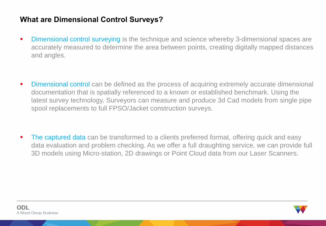
What are Dimensional Control Surveys?
3 www.woodgroupodl.com
Dimensional control surveying is the technique and science whereby 3-dimensional spaces are
accurately measured to determine the area between points, creating digitally mapped distances
and angles.
Dimensional control can be defined as the process of acquiring extremely accurate dimensional
documentation that is spatially referenced to a known or established benchmark. Using the
latest survey technology, Surveyors can measure and produce 3d Cad models from single pipe
spool replacements to full FPSO/Jacket construction surveys.
The captured data can be transformed to a clients preferred format, offering quick and easy
data evaluation and problem checking. As we offer a full draughting service, we can provide full
3D models using Micro-station, 2D drawings or Point Cloud data from our Laser Scanners.
What are Dimensional Control Surveys?

4 www.woodgroupodl.com
Your Challenges- Lack of knowledge of installation, clear visibility, little or no accurate data
The Benefits - Preventing failures to fit, clash free installations, client owned reusable data,
asset integrity, familiarisation, HSE, accurate repairs, upgrades and maintenance etc.
Reduce Costs – cost effective, multi use data, such as construction planning, reduce “hot-
work”, increase in safety, reduce on site material handling, “Zero failures to fit”. Reduce the
number of offshore visits
Dimensional Control can meet these challenges and help ensure "clash-free" design and
installation of projects involving piping, structural and equipment that must integrate and “fit first
time”.
Fabric & Maintenance, HSE, Familiarisation & Induction, Training, Emergency Response
Why use Dimensional Control Surveys?

5 www.woodgroupodl.com
Who are we?
• Global Leaders in Dimensional Control
• Providing High-Quality, Cutting Edge Surveys to Suit Every Client's Unique
Requirements
• Zero Failures to Fit

6 www.woodgroupodl.com
Introduction
Wood Group ODL Dimensional Control Surveys provide cost effective dimensional control
services to the Oil & Gas Industry:
A Global team of experienced surveyors – using proven technology
Considerable experience of surveying offshore platforms and onshore installations for the oil
and gas industry
Precision survey data to fabricate items that fit when installed, without clashes

7 www.woodgroupodl.com
Why are we the best choice?
• Access to surveyors by BG project teams
• Ease of sharing data
• Communication and responsiveness
• Leading technologies on the market
• Highly qualified team of surveyors
• Output customized to customer needs

8 www.woodgroupodl.com
How do we capture the data?
Laser scanner – uses
controlled steering of laser
beams followed by a
distance measurement at
every pointing direction, to
capture the shape of
objects, buildings and
landscapes. Captures large
amount of spatial data in
short period of time.
Total station – a theodolite
integrated with an
electronic distance meter to
read distances from the
instrument to a particular
point with the highest
accuracy. Used for small,
high accuracy tasks (e.g.
tie point surveys)
Camera with a fisheye lens
on a panoramic bracket –
used to capture a complete
panoramic view from each
scan position. The image
can be integrated with laser
scans. Used to produce
highest quality Truviews.

9 www.woodgroupodl.com
What do we offer?
• Clear, high-resolution pictures of as-built
installations
• Accurate measurements to plan and design tie-
ins
• Visualization of potential clashes
• Re-usable surveys
• Flexibility to change scope
• Truview panoramas, available for everyone as
freeware
• Integration with PDMS, AutoCAD, Microstation
and Navisworks
10 www.woodgroupodl.com
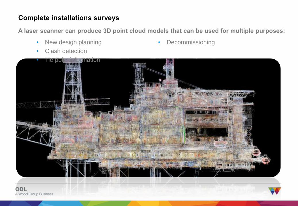
Complete installations surveys
A laser scanner can produce 3D point cloud models that can be used for multiple purposes:
• New design planning
• Clash detection
• Tie point information
• Decommissioning

11 www.woodgroupodl.com
Whole-life Asset Support
Government Negotiations Seismic Assessment Exploration / Appraisal Drilling Development Project Operation (Production) Downstream Decommissioning Relinquish License
LogisticsProduction FacilitiesDrillingWells / Drilling ManagementReservoir and Production
Development Project Operations Maintenance Modifications Downstream Decommissioning
Operating Profit
Development Costs
Brownfield Activity
Wood Group PSN Core Services
Supporting your asset throughout its life – from fabrication to decommissioning
12 www.woodgroupodl.com
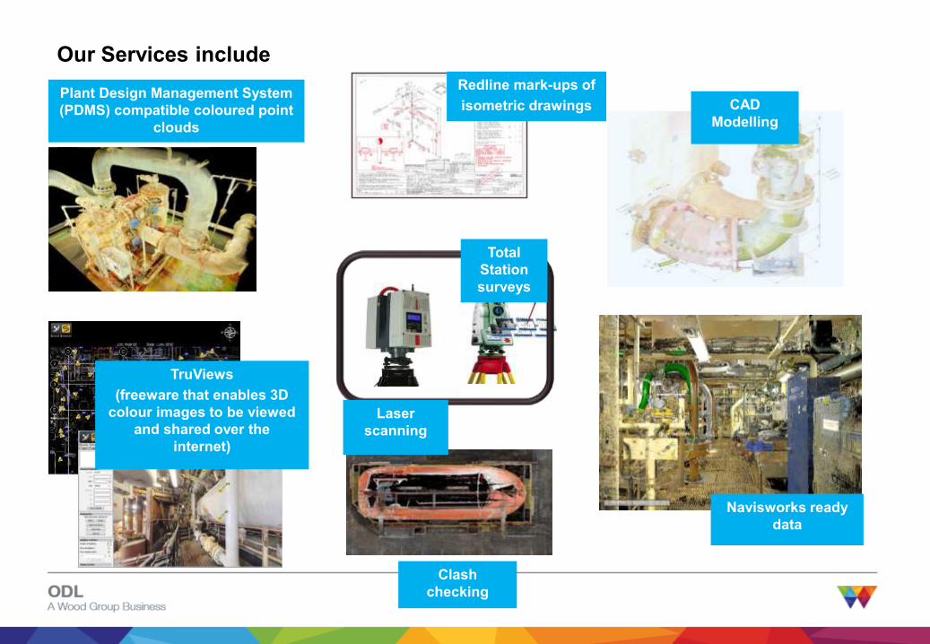
Our Services include
Laser
scanning
Total
Station
surveys
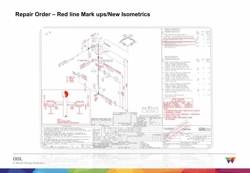
Redline mark-ups of
isometric drawingsPlant Design Management System
(PDMS) compatible coloured point
clouds
TruViews
(freeware that enables 3D
colour images to be viewed
and shared over the
internet)
Clash
checking
CAD
Modelling
Navisworks ready
data
13 www.woodgroupodl.com
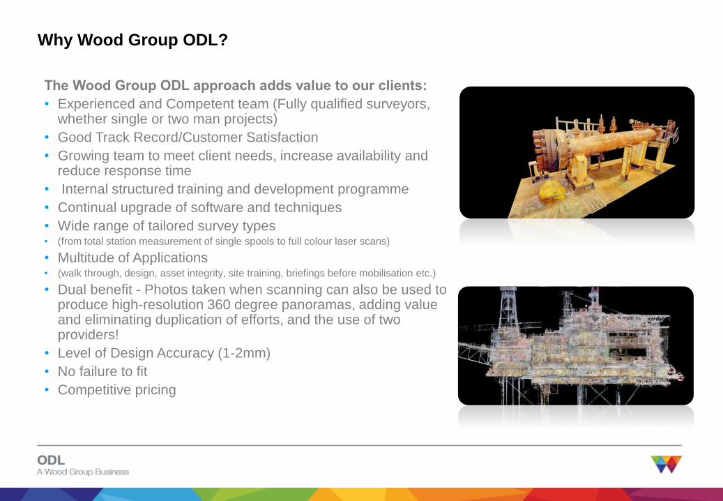
Why Wood Group ODL?
The Wood Group ODL approach adds value to our clients:
• Experienced and Competent team (Fully qualified surveyors, whether single or two man projects)
• Good Track Record/Customer Satisfaction
• Growing team to meet client needs, increase availability and reduce response time
• Internal structured training and development programme
• Continual upgrade of software and techniques
• Wide range of tailored survey types • (from total station measurement of single spools to full colour laser scans)
• Multitude of Applications • (walk through, design, asset integrity, site training, briefings before mobilisation etc.)
• Dual benefit - Photos taken when scanning can also be used to produce high-resolution 360 degree panoramas, adding value and eliminating duplication of efforts, and the use of two providers!
• Level of Design Accuracy (1-2mm)
• No failure to fit
• Competitive pricing

14 www.woodgroupodl.com
Innovation and Development of New Services
• Close links with industry:
• Test latest technology
• Only adopt if it provides additional benefits
• Manage scan data from all sources
• Enable project team, ops, construction etc to
have access to most recent scan data
• Asset management
• Use scan data as portal for:• Maintenance information
• Asset integrity
• Web-based to allow widespread access
• Condition monitoring
• Respond to customer requirements
15 www.woodgroupodl.com
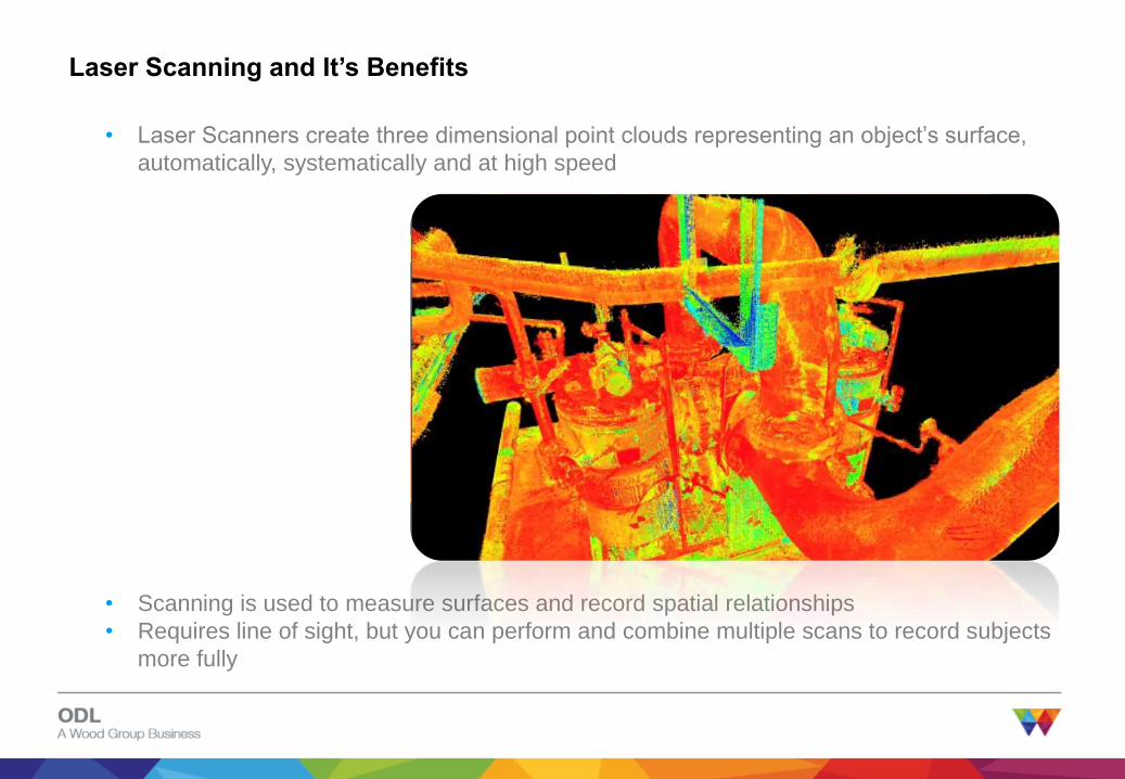
Laser Scanning and It’s Benefits
• Scanning is used to measure surfaces and record spatial relationships
• Requires line of sight, but you can perform and combine multiple scans to record subjects
more fully
• Laser Scanners create three dimensional point clouds representing an object’s surface,
automatically, systematically and at high speed

16 www.woodgroupodl.com
• 3D measurements of distances and volumes
• Clash detection
• Design visualisations
Manipulation of the Point Cloud

17 www.woodgroupodl.com
What level of detail can we capture? What accuracy?

18 www.woodgroupodl.com
How do we do that?

19 www.woodgroupodl.com
Design visualization
20 www.woodgroupodl.com
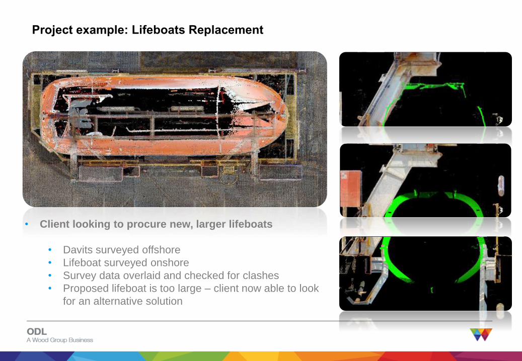
Project example: Lifeboats Replacement
• Client looking to procure new, larger lifeboats
• Davits surveyed offshore
• Lifeboat surveyed onshore
• Survey data overlaid and checked for clashes
• Proposed lifeboat is too large – client now able to look
for an alternative solution
21 www.woodgroupodl.com
Repair Order – Red line Mark ups/New Isometrics
22 www.woodgroupodl.com
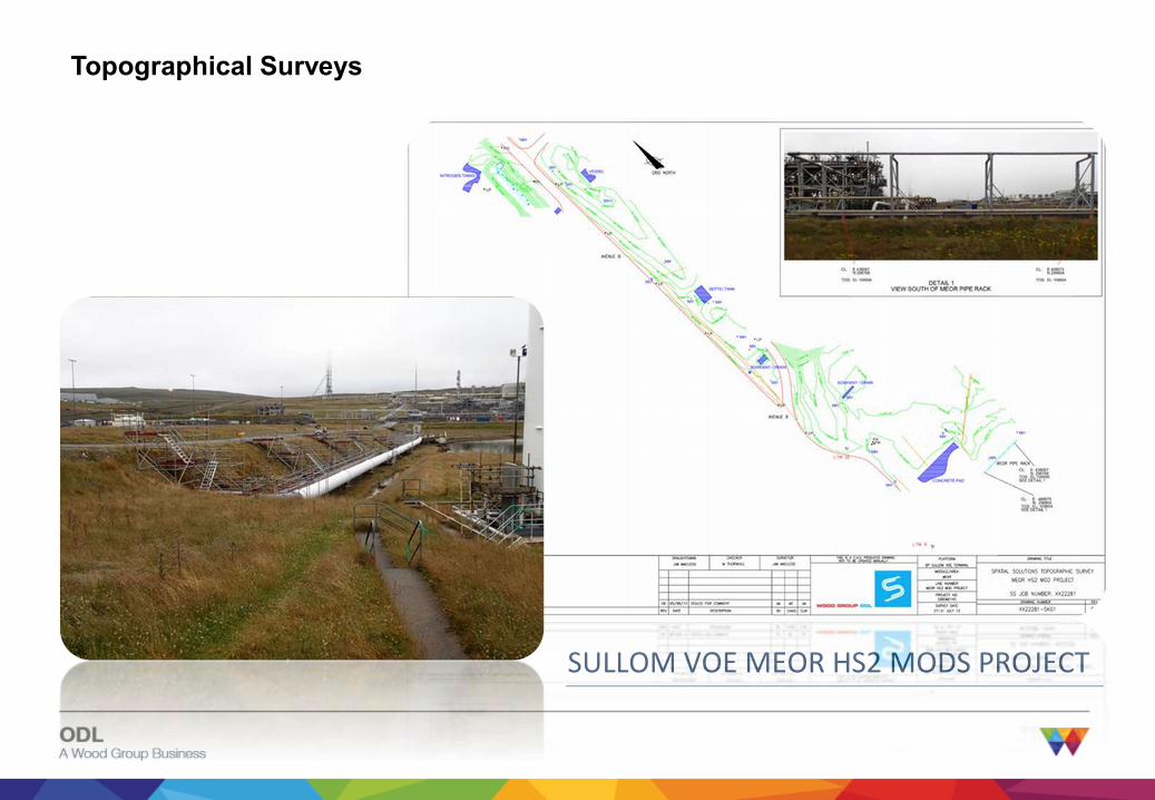
SULLOM VOE MEOR HS2 MODS PROJECT
Topographical Surveys
23 www.woodgroupodl.com
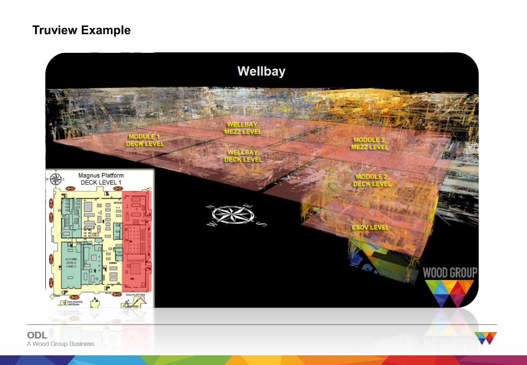
Truview Example
24 www.woodgroupodl.com
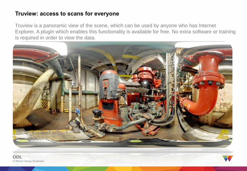
Truview: access to scans for everyone
Truview is a panoramic view of the scene, which can be used by anyone who has Internet
Explorer. A plugin which enables this functionality is available for free. No extra software or training
is required in order to view the data.

25 www.woodgroupodl.com
Truview: access to scans for everyone
The image is enhanced so that basic measurements can be taken directly on the screen:

26 www.woodgroupodl.com
How do we work?
The scheme below shows the usual workflow of a typical project:
Survey
request
from Client
Surveyor
allocated to
job
Surveyor
discusses
requirement
s with Client
Finalise scope
of work,
survey method
and
deliverables
Prepare kit
for air freight
or despatch
by boat
Mobilise.
Complete site
inductions and
obtain permit
to work
Perform the
survey
Return to
office,
process data
Final scans,
models and
drawings
delivered to
Client

27 www.woodgroupodl.com
Any Questions?

28 www.woodgroupodl.com
Proposed Dimensional Control Pilot Survey
• Proposed Pilot – what are your challenges? We will pilot the survey to give the best
results to address the current issues you have. We would suggest consideration is given
to any new equipment installation, such as, skids, pumps, pipes etc.
• Duration- we would suggest 2 weeks on the facility
• Team – this would be a two man team on site working 12 hour shifts
• Outputs - we will produce a full colour 3D virtual model of the facility, TruViews and
drawings/redline mark-ups.

29 www.woodgroupodl.com
Contacts
Stewart Buchanan: Wood Group ODL
+44 07738 405529
Michael Sakr: Autochim Systems
971 2 6265774

30 www.woodgroupodl.com
List of Survey Equipment Required
The following equipment will be required for the duration of this survey,
and will be shipped to the platform prior to the survey. Upon completion
of the offshore survey the equipment will be returned to the ODL office
in Aberdeen:

31 www.woodgroupodl.com
To be hand-carried by surveyors:
• Dell Precision Laptop
• Olympus TG1 camera
• Tape measure & steel rule
• PPE bag
32 www.woodgroupodl.com
Clarifications
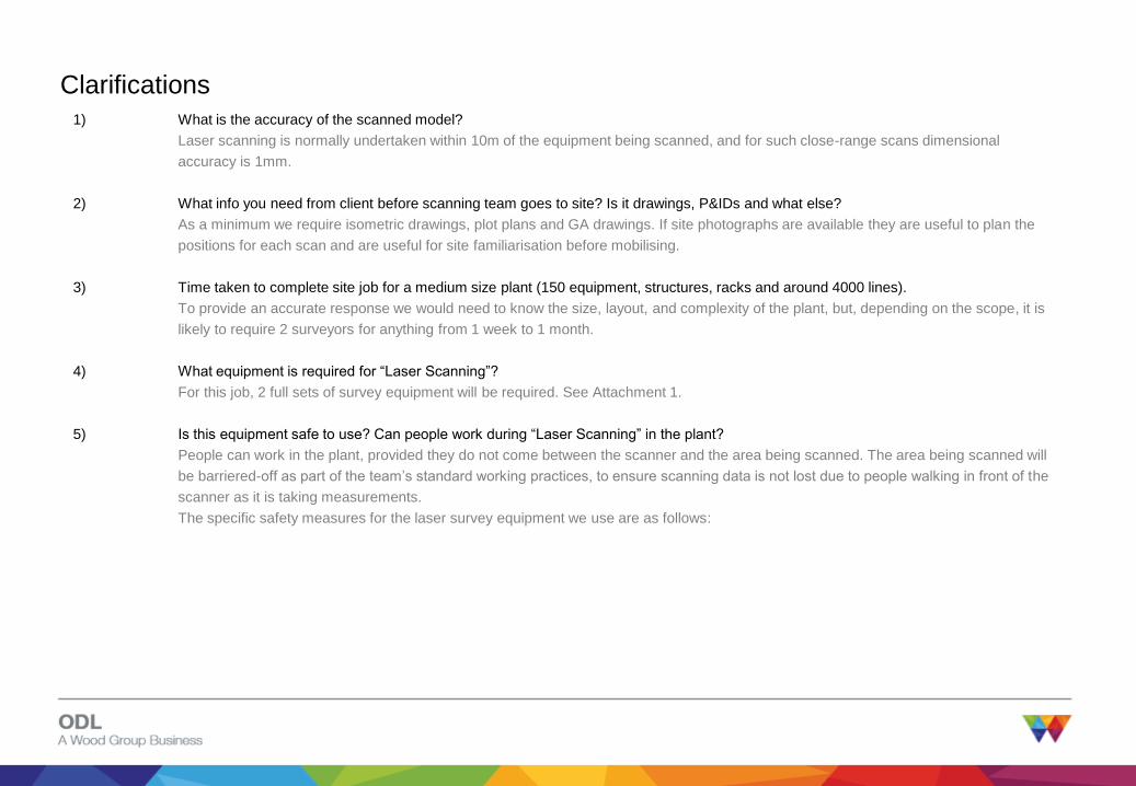
1) What is the accuracy of the scanned model?
Laser scanning is normally undertaken within 10m of the equipment being scanned, and for such close-range scans dimensional
accuracy is 1mm.
2) What info you need from client before scanning team goes to site? Is it drawings, P&IDs and what else?
As a minimum we require isometric drawings, plot plans and GA drawings. If site photographs are available they are useful to plan the
positions for each scan and are useful for site familiarisation before mobilising.
3) Time taken to complete site job for a medium size plant (150 equipment, structures, racks and around 4000 lines).
To provide an accurate response we would need to know the size, layout, and complexity of the plant, but, depending on the scope, it is
likely to require 2 surveyors for anything from 1 week to 1 month.
4) What equipment is required for “Laser Scanning”?
For this job, 2 full sets of survey equipment will be required. See Attachment 1.
5) Is this equipment safe to use? Can people work during “Laser Scanning” in the plant?
People can work in the plant, provided they do not come between the scanner and the area being scanned. The area being scanned will
be barriered-off as part of the team’s standard working practices, to ensure scanning data is not lost due to people walking in front of the
scanner as it is taking measurements.
The specific safety measures for the laser survey equipment we use are as follows:
33 www.woodgroupodl.com
Clarifications
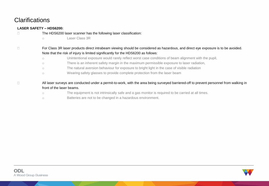
LASER SAFETY – HDS6200:
The HDS6200 laser scanner has the following laser classification:
o Laser Class 3R
For Class 3R laser products direct intrabeam viewing should be considered as hazardous, and direct eye exposure is to be avoided.
Note that the risk of injury is limited significantly for the HDS6200 as follows:
o Unintentional exposure would rarely reflect worst case conditions of beam alignment with the pupil,
o There is an inherent safety margin in the maximum permissible exposure to laser radiation,
o The natural aversion behaviour for exposure to bright light in the case of visible radiation
o Wearing safety glasses to provide complete protection from the laser beam
All laser surveys are conducted under a permit-to-work, with the area being surveyed barriered-off to prevent personnel from walking in
front of the laser beams.
o The equipment is not intrinsically safe and a gas monitor is required to be carried at all times.
o Batteries are not to be changed in a hazardous environment.

34 www.woodgroupodl.com
LASER SAFETY – TOTAL STATIONS:
The TS11 and TCRP1201+ total stations both have the following laser classifications:o Laser Class 1 for measurements with reflectors
o Laser Class 3R for measurements without reflectors
o Laser Class 2 for plummet (laser beam points directly at ground level)
Class 1 laser products are not harmful to the eyes provided they are used in accordance with the manufacturer’s instructions.
For Class 3R laser products direct intrabeam viewing should be considered as hazardous, and direct eye exposure is to be avoided.
Note that the risk of injury is limited signkificantly for either model of Total Station, as follows:o Unintentional exposure would rarely reflect worst case conditions of beam alignment with the pupil,
o There is an inherent safety margin in the maximum permissible exposure to laser radiation,
o The natural aversion behaviour for exposure to bright light in the case of visible radiation
o Wearing safety glasses to provide complete protection from the laser beam
Class 2 laser products are safe for momentary exposures, but can be hazardous for deliberate staring into the beam. The beam is not to
be pointed at others.
All surveys are conducted under a permit-to-work, with the area being surveyed barriered-off to prevent personnel from walking in front
of the laser beams.o The equipment is not intrinsically safe and a gas monitor is required to be carried at all times.
o Batteries are not to be changed in a hazardous environment.
35 www.woodgroupodl.com
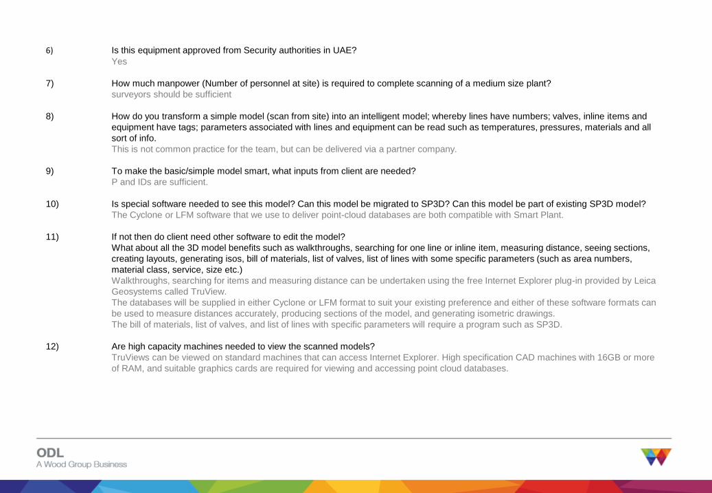
6) Is this equipment approved from Security authorities in UAE?
Yes
7) How much manpower (Number of personnel at site) is required to complete scanning of a medium size plant?
surveyors should be sufficient
8) How do you transform a simple model (scan from site) into an intelligent model; whereby lines have numbers; valves, inline items and
equipment have tags; parameters associated with lines and equipment can be read such as temperatures, pressures, materials and all
sort of info.
This is not common practice for the team, but can be delivered via a partner company.
9) To make the basic/simple model smart, what inputs from client are needed?
P and IDs are sufficient.
10) Is special software needed to see this model? Can this model be migrated to SP3D? Can this model be part of existing SP3D model?
The Cyclone or LFM software that we use to deliver point-cloud databases are both compatible with Smart Plant.
11) If not then do client need other software to edit the model?
What about all the 3D model benefits such as walkthroughs, searching for one line or inline item, measuring distance, seeing sections,
creating layouts, generating isos, bill of materials, list of valves, list of lines with some specific parameters (such as area numbers,
material class, service, size etc.)
Walkthroughs, searching for items and measuring distance can be undertaken using the free Internet Explorer plug-in provided by Leica
Geosystems called TruView.
The databases will be supplied in either Cyclone or LFM format to suit your existing preference and either of these software formats can
be used to measure distances accurately, producing sections of the model, and generating isometric drawings.
The bill of materials, list of valves, and list of lines with specific parameters will require a program such as SP3D.
12) Are high capacity machines needed to view the scanned models?
TruViews can be viewed on standard machines that can access Internet Explorer. High specification CAD machines with 16GB or more
of RAM, and suitable graphics cards are required for viewing and accessing point cloud databases.