Embed Size (px)
Citation preview

1
Unit-4Waves and applications
Mr. HIMANSHU DIWAKARAssistant ProfessorGETGI
Himanshu Diwakar, AP

2
Learning objectives
• Faraday’s Laws• Various Induced Emf’s Directions and Magnitude• Practical applications
Himanshu Diwakar, AP
3
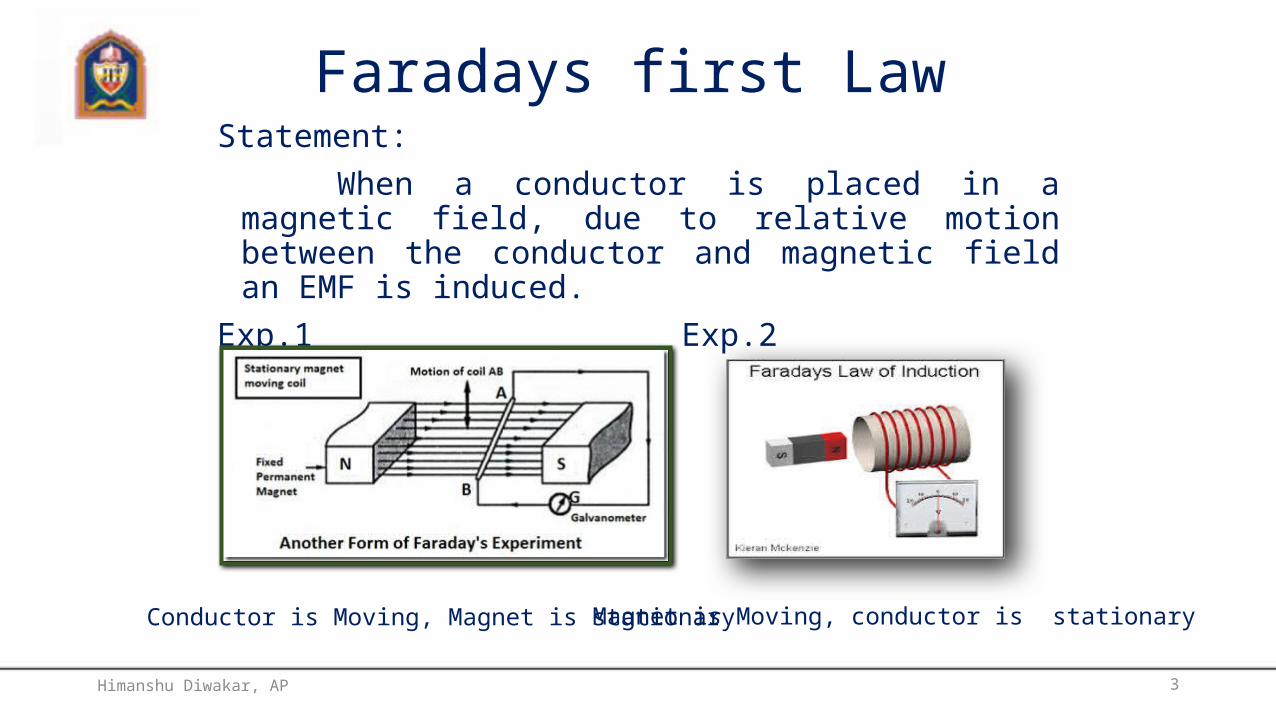
Magnet is Moving, conductor is stationary
Faradays first LawStatement:
When a conductor is placed in a magnetic field, due to relative motion between the conductor and magnetic field an EMF is induced.
Exp.1 Exp.2
Conductor is Moving, Magnet is stationary
Himanshu Diwakar, AP

4
Faraday’s Second law
Statement:
The magnitude of induced EMF is directly proportional to the rate of Change of Flux linkages.
Dynamically Induced EMF Statically Induced EMF Self Induced EMF Mutual Induced EMF
Himanshu Diwakar, AP

5
Magnitude and direction of Dynamically induced EMF
Right hand Thumb rule
E=BLV SIN
E= Induced EMF in voltsB= Magnetic Flux Density in webersV= velocity m/sec
= Angle between flux and conductor position
Himanshu Diwakar, AP

6
Dynamically induced EMF
• EMF produced due to space variation between the magnetic field and the conducto
AlternatorDC GeneratorHimanshu Diwakar, AP

7
Negative sign indicates the opposition
Statically Induced EMF• EMF produced due to the time variation of flux linking with the stationary
conductor.
Self induced EMF Mutually induced EMF
Himanshu Diwakar, AP
8
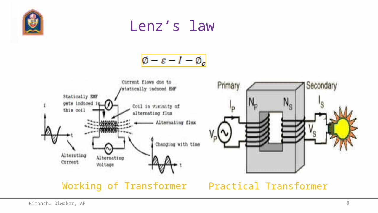
Lenz’s law
Working of Transformer Practical Transformer
Himanshu Diwakar, AP
9
Displacement current
Himanshu Diwakar, AP

10
Recall Ampere’s Law
encIsdB 0
Himanshu Diwakar, AP
11
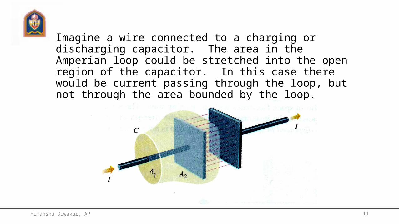
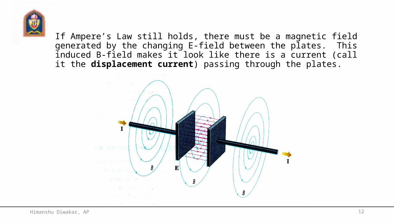
Imagine a wire connected to a charging or discharging capacitor. The area in the Amperian loop could be stretched into the open region of the capacitor. In this case there would be current passing through the loop, but not through the area bounded by the loop.
Himanshu Diwakar, AP
12
If Ampere’s Law still holds, there must be a magnetic field generated by the changing E-field between the plates. This induced B-field makes it look like there is a current (call it the displacement current) passing through the plates.
Himanshu Diwakar, AP

13
Properties of the Displacement Current
• For regions between the plates but at radius larger than the plates, the B-field would be identical to that at an equal distance from the wire.
• For regions between the plates, but at radius less than the plates, the Ienc would be determined as through the total I were flowing uniformly between the plates.
Himanshu Diwakar, AP

14
Equation for Displacement current
dtdI E
d
0
Himanshu Diwakar, AP

15
Modified Ampere’s Law (Ampere-Maxwell Law)
dtdIsdB
IIsdB
Eenc
encdenc
000
,00
Himanshu Diwakar, AP
16
Maxwell’s Equations
h
09-18-2008Himanshu Diwakar, AP
17
Content sField equationsEquation of continuity for time varying fieldsInconsistency of Ampere’s LawMaxwell’s equationsConditions at a Boundary surfaces
Himanshu Diwakar, AP

18
The equations governing electric field due to charges at rest and the static magnetic field due to steady currents are
Contained in the above is the equation of continuity Time Varying Fields:From Faraday’s Law
In time varying electric and magnetic fields path of integration can be considered fixed. Faraday’s Law
becomes Hence 1st equation becomes
0.dsE
D. dvdaD .
JH daJdsH ..
0. B 0. daB
0. J 0.daJ
s
daBdtd
dtddsE ..
datBdsE
s
..
s
datBdsE ..
0 E
tBE
Himanshu Diwakar, AP

19
Equation of continuity for Time-Varying Fields:
From conservation of charge concept
if the region is stationary
Divergence theorem
time varying form of equation of Continuity
Inconsistency of Ampere’s Law:Taking divergence of Ampere’s law hence Ampere’s law is not consistent for time varying equation of continuity.
(from Gauss’s Law)
displacement current density.
dVdtddaJ .
dVt
daJ .
dVt
JdV .
tJ
.
JH .).( 0J
Dt
J ..
0.
JtD
0.
daJtD
Himanshu Diwakar, AP

20
Hence Ampere’s law becomes .Now taking divergence results equation of continuity
Integrating over surface and applying Stokes’s theorem
magneto motive force around a closed path=total current enclosed by the path.
Maxwell’s equations: These are electromagnetic equations .one form may be derived from the other with the help of Stoke’s
theorem or the divergence theorem
Contained in the above is the equation of continuity.
JtDH
daJtDdsH ..
JtDH
daJtDdsH ..
tBE
datBdsE ..
D. dVdaD .
0. B 0.daB
tJ
. dV
tdaJ
.
Himanshu Diwakar, AP

21
Word statement of field equation:1. The magneto motive force (magnetic voltage)around a closed path is equal to the conduction current plus the
time derivative of electric displacement through any surface bounded by the path.
2. The electromotive force (electric voltage)around a closed path is equal to the time derivative of magnetic displacement through any surface bounded by the path
3. Total electric displacement through the surface enclosing a volume is equal to the total charge wihin the volume.
4. The net magnetic flux emerging through any closed surface is zero.
Interpretation of field equation:Using Stokes’ theorem to Maxwell’s 2nd equation
Again from Faraday’s law region where there is no time varying magnetic flux ,voltage
around the loop would be zero the field is electrostatic and irrational.
Again
there are no isolated magnetic poles or “magnetic charges” on which lines of magnetic flux can terminate(the lines of mag.flux are continuous)
dsEdaE ..da
dsEnE
.ˆ.
tBE
0 E0. B
Himanshu Diwakar, AP

22
Boundary condition:1. E,B,D and H will be discontinuous at a boundary between two different media or at surface that
carries charge density σ and current density K2. Discontinuity can be deduced from the Maxwell’s equations
1. over any closed surface S 2.
3. for any surface S bounded by closed loop p
4.
From 1
Spf
Sp
S
Sf
daDdtdIdlH
daBdtddlE
daB
QdaD
enc
enc
..
..
0.
.
f
f
DD
aaDaD
21
21 ..1
2
f
D2
D1
a
Himanshu Diwakar, AP

25
For metallic conductor it is zero for electrostatic case or in the case of a perfect conductor
normal component of the displacement density of dielectric = surface charge density of on the conductor.
Similar analysis leads for magnetic field
ED
snD 1
21 nn BB
Himanshu Diwakar, AP

26
Electromagnetic Waves in homogeneous medium:The following field equation must be satisfied for solution of electromagnetic problem
there are three constitutional relation which determines
characteristic of the medium in which the fields exists.
Solution for free space condition:
In particular case of e.m. phenomena in free space or in a perfect dielectric containing no charge and
no conduction current
Differentiating 1st
JtDH
tBE
D.
0. B EJHBED
tDH
tBE
0. D0. B
tH
tH
Himanshu Diwakar, AP
27
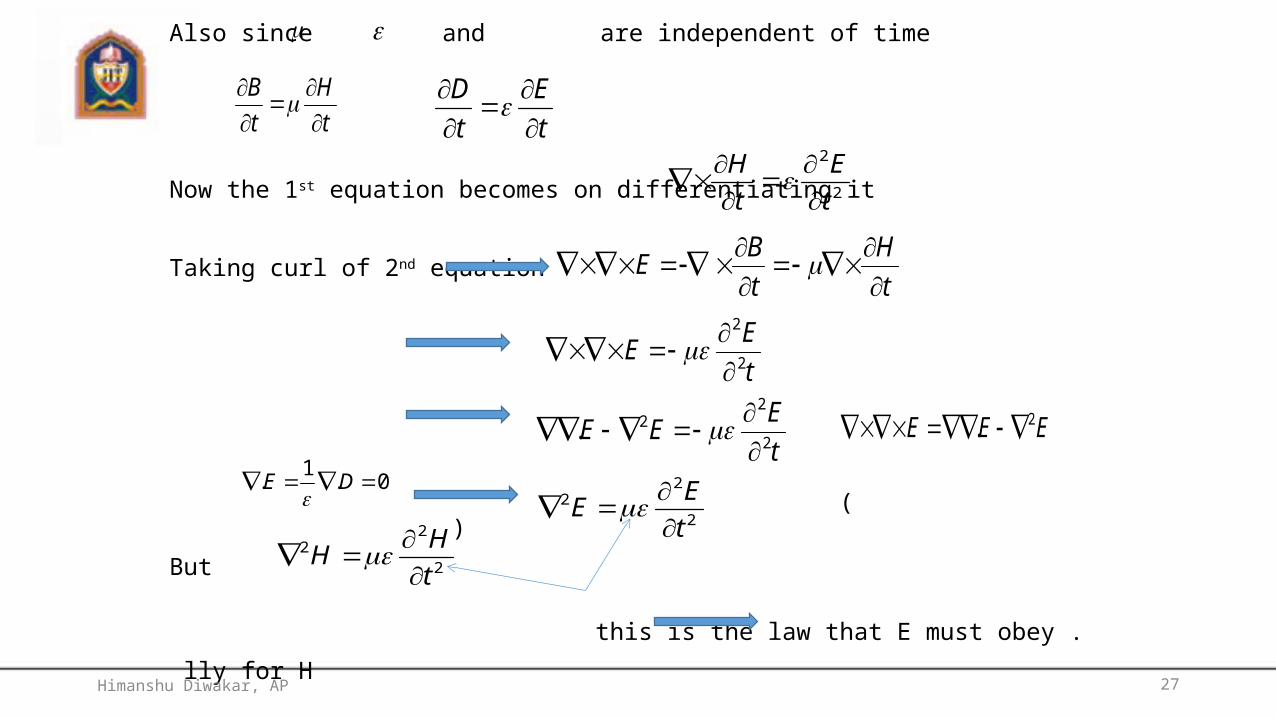
Also since and are independent of time
Now the 1st equation becomes on differentiating it
Taking curl of 2nd equation
( )
But
this is the law that E must obey .
lly for H
these are wave equation so E and H satisfy wave equation.
tH
tB
tE
tD
2
2
tE
tH
tH
tBE
tEE 2
2
tEEE 2
22.
EEE 2.
0.1. DE
2
22
tEE
2
22
tHH
Himanshu Diwakar, AP

28
Uniform Plane wave propagation:If E and H are considered to be independent of two dimensions say X and Y
For uniform wave propagation differential equation equation for voltage or
current along a lossless transmission line.
General solution is of the form
reflected wave.
Uniform Plane Wave:
Above equation is independent of Y and Z and is a function of x and t only .such a wave is uniform plan
wave. the plan wave equation may be written as component of E
2
2
2
2
tE
xE
2
2
2
2
tE
xE yy
tvxftvxfE 0201
2
2
2
2
tE
xE
2
2
2
2
2
2
2
2
2
2
2
2
tE
xE
tE
xE
tE
xE
zz
yy
xx
Himanshu Diwakar, AP
29
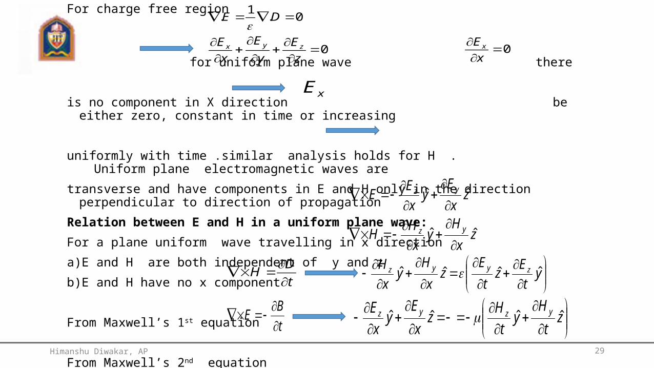
For charge free region
for uniform plane wave there
is no component in X direction be either zero, constant in time or increasing
uniformly with time .similar analysis holds for H . Uniform plane electromagnetic waves are
transverse and have components in E and H only in the direction perpendicular to direction of propagation
Relation between E and H in a uniform plane wave:For a plane uniform wave travelling in x direction
a)E and H are both independent of y and z
b)E and H have no x component
From Maxwell’s 1st equation
From Maxwell’s 2nd equation
0
0.1.
zE
yE
xE
DE
zyx
0xEx
xE
zxH
yxHH
zxE
yxEE
yz
yz
ˆˆ
ˆˆ
tDH
ytEz
tE
zxH
yxH zyyz ˆˆˆˆ
tBE
ztH
ytHz
xE
yxE yzyz ˆˆˆˆ
Himanshu Diwakar, AP

30
Comparing y and z terms from the above equations
on solving finally we get
lly Since
The ratio has the dimension of impedance or ohms , called characteristic impedance or intrinsicimpedance of the (non conducting) medium. For space
tH
xE
tH
xE
tE
xH
tE
xH
zy
yz
zy
yz
y
z
z
y
yz
HE
HE
EH
22
22
zy
zy
HHH
EEE
HE
ohms
mhenry
v
v
v
v
377120
10361
/104
9
7
Himanshu Diwakar, AP

31
ohmsv
vv 377
The relative orientation of E and H may be determined by taking their dot product and using above relation
In a uniform plane wave ,E and H are at right angles to each other.
electric field vector crossed into the magnetic field vector gives the direction in which the wave travells.
0. zyzyzzyy HHHHHEHEHE
222 ˆˆˆ HxHHxHEHExHE yzyzzy
Himanshu Diwakar, AP

32
Thank you
Himanshu Diwakar, AP