Embed Size (px)
Citation preview

Industrial Control andAutomation
Unit-3 Computer NumericalControl

Contents
• Introduction to CNC Systems
• Types –Analogue & Digital CNC System
• Absolute and Incremental
• Open Loop System and Closed Loop System
• CNC Drives
• Classification and Operation
• Feedback Devices-Adaptive Control
• CNC Part Programming.
19-09-2016 [email protected] 2

Introduction to CNC Systems
• CNC is defined as an NC system whose microcontroller isbased on a dedicated microcomputer rather than on a hard-wired controller.
• The numerical data required to produce a part is providedto a machine in the form of program, called part program orCNC (computer numerical control)
• The program is translated into the appropriate electricalsignals for input to motors that run the machine.
19-09-2016 [email protected] 3

Milestones in the development of CNC Machine
1775• John Wilkinson- cannon boring machine (lathe)
1881•Eli Whitney- milling machine
1947•Mr. John Parsons began experimenting for using 3-axis curvature data to
control the machine tool motion for the production for aircraft components.
1949•parsons- first NC machine
1951•MIT was involved in the project
1955•after refinements NC became available in industry
2016•Today, modern machinery are CNC milling machines and lathes.
19-09-2016 [email protected] 4

Features of CNC Machine
• Storage of more than one part program
• Various form of program input
• Program editing in machine tool
• Fixed cycles and program subroutines
• Interpolation
• Positioning feature for setup
• Cutter length and tool compensation
• Acceleration and deceleration calculation
• Communication interface
19-09-2016 [email protected] 5

• Diagnostic tools• Control start-up diagnostics
• malfunction and failure analysis
• Extended diagnostics for individual components
• Tool life monitoring
• Preventive maintenance notices
• Programming diagnostics
19-09-2016 [email protected] 6

Subsystems of MCU for CNC
• Central Processing Unit (CPU)Control section
Arithmetic-logic unit
Immediate Access Memory
• Memory
• Input/ Output Interface
• Control for Machine Tool Axes and Spindle Speed
• Sequence Control for other machine tool function
• Personal Computer and the MCU
19-09-2016 [email protected] 8

Analysis on Positioning Systems
• The NC positioning system converts the coordinateaxis values in the NC part program into relativepositions of the tool and work part during processing.
• The worktable moves linearly by means of a rotatinglead screw, which is driven by a stepping motor orservomotor.
• The velocity of the worktable, which corresponds tothe feed rate in a machining operation, is determinedby the rotational speed of the lead screw,
19-09-2016 [email protected] 9

• There are two types of positioning systems used in NC systems:
(a) open loop and
(b) closed loop,
19-09-2016 [email protected] 10

Open Loop Positioning System
• Operates without verifying the actual positionachieved in the move is same as the desiredposition
• Cost is less than the Closed loop system and areappropriate when the force resisting the actualmotion is minimal
19-09-2016 [email protected] 11

• It uses a stepping motor to rotate the leadscrew a stepping motor is driven by a series ofelectrical pulses, which are generated by theMCU in an NC system.
• Each pulse causes the motor to rotate a fractionof one revolution called the step angle.
• The possible step angles must be consistentwith the following relationship:
19-09-2016 [email protected] 12

• The angle through which the motor shaft rotates is given by
• The motor shaft is generally connected to the lead screw through a gear box, which reduces the angular rotation of the lead screw.
19-09-2016 [email protected] 13

• The linear movement of the worktable is given by the number of full and partial rotations of the lead screw multiplied by its pitch:
• Control pulses are transmitted from the pulsegenerator at a certain frequency, which drives theworktable at a corresponding velocity or feed rate inthe direction of the lead screw axis.
• The rotational speed of the lead screw depends on thefrequency of the pulse train .
• The table travel speed in the direction of lead screwaxis is determined by the rotational speed.
19-09-2016 [email protected] 14

Closed Loop System
• It uses feedback measurements to confirm that thefinal position of the worktable is the locationspecified in the program.
• Mostly used for continuous path operations such asmilling or turning, in which there are significantforces resisting the forward motion of the cuttingtool
19-09-2016 [email protected] 15

• It uses servomotors and feedback measurements toensure that the worktable is moved to the desiredposition
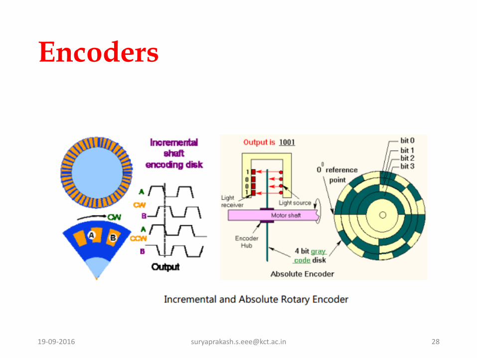
• Commonly used feed back sensor is OpticalEncoder
• optical encoder consists of a light source and aphoto detector on either side of a disk
• The disk contains slots uniformly spaced aroundthe outside of its face. These slots allow the lightsource to shine through and energize the photodetector.
19-09-2016 [email protected] 16

• The flashes are converted into an equal number of electrical pulses.
• By counting the pulses and computing the frequency of the pulse train, worktable position and velocity can be determined
19-09-2016 [email protected] 17

• In the basic optical encoder, the angle between slots in the disk must satisfy the following requirement:
• The pulse count can he used to determine the linear x-axis position of the worktable by factoring in the leadscrew pitch and the gear reduction between theencoder shaft and the lead screw.
• The velocity of the worktable, which is normally thefeed rate in a machining operation, is obtained fromthe frequency of the pulse train.
19-09-2016 [email protected] 18

• The pulse train generated by the encoder is comparedwith the coordinate position and feed rate specified inthe part program and the difference is used by theMCV to drive a servomotor, which in turn drives theworktable.
• A digital-to-analog converter converts the digitalsignals used by the MCU into a continuous analogcurrent that powers the drive motor.
• Metal cutting machine tools that perform continuouspath cutting operations, such as milling and turning,fall into this category
19-09-2016 [email protected] 19

CNC Software• Operating System Software- to interpret the NC part programs and
generate the corresponding control signals to drive the machine tool
axes.
1. Editor -which permits the machine operator to input and edit NC part
programs and perform other file management functions
2. Control Program- which decodes the part program instructions, performs
interpolation and acceleration /deceleration calculations, and
accomplishes other related functions to produce the coordinate control
signals for each axis.
3. Executive Program-which manages the execution of the CNC software as
well as the I/O operations of the MCU.
19-09-2016 [email protected] 20
• Machine Interface Software-to operate the communication link between the
CPU and the machine tool to accomplish the CNC auxiliary functions
• Application Software- applications in the user's plant.
19-09-2016 [email protected] 21

Driving System
• It must response accurately according to the programmed instruction
• Mostly electric motor for small tools and hydraulics for large tools
• Motor is coupled directly to the gear box to the machine lead screw to
slide or spindle
• Four types of electrical driving system used are
DC Servo Motor
AC Servo Motor
Stepping Motor
Linear Motor
19-09-2016 [email protected] 22

Feed back Devices
• In order to operate accurately machine should be updated with good positional and velocity feedback devices.
• Positional Feedback Devices1. Linear Transducer
2. Rotary Encoder
• Velocity Feed back Devices
19-09-2016 [email protected] 27

CNC Part Programming
• planning and documenting the sequence of processingsteps to be performed on an NC machine.
• Traditional input medium dating back to the first NCmachines in 1950s is l-inch wide punched tape
• More recently the use of magnetic tape and floppydisks were used due to high data intensity.
• The methods are:1. manual part programming,
2. computer-assisted part programming,
3. part programming using CAD/CAM. and
4. manual data input.
19-09-2016 [email protected] 30

NC Coding System
• Low Level Languages- Binary Number
- Binary Coded Decimal
• High Level Languages-APT( Automated Programming tools)
19-09-2016 [email protected] 31

19-09-2016 [email protected] 33

Dimension system
• Incremental System• Sequence of Points
• Error will be accumulated
19-09-2016 [email protected] 35

Definition of Programming
“all machining data is compiled and where the data are translated into language which can be
understood by the control system of machine tool”
Machine Sequence- classification of process, tool start point, cutting depth , tool path etc.,
Cutting Condition spindle speed, feed rate, coolant, etc
Selecting of cutting tools
19-09-2016 [email protected] 37

19-09-2016 [email protected] 39

19-09-2016 [email protected] 41

19-09-2016 [email protected] 42
19-09-2016 [email protected] 43

19-09-2016 [email protected] 44

19-09-2016 [email protected] 45

19-09-2016 [email protected] 46

19-09-2016 [email protected] 48