Embed Size (px)
Citation preview

Mentor: Mr. D.K. Raheja Presented by:
Name: Ashwini Kumar Naresh
Branch: RF and Microwave
Roll No.: 00410100613

Abstract The objective of this paper is to provide the context,
physical insight, and perspective on antennas in wireless communications.
Although it does not mean to be comprehensive, the four key technologies related to small antenna designs to be reviewed and discussed, including multiband planar inverted-F antennas, broadband folded patch antennas, compact differentially fed antennas, and miniature circularly polarized patch antennas, would cover a wide range of topical interests and practical applications.

Introduction Numerous wireless communications systems have
been successfully developed and deployed in recent years.
Wireless devices such as cell phones, tablets, laptops, Bluetooth earphones, game pad controllers, Global Positioning System (GPS) receivers, and security sensors are very common in our daily life.
They require different kinds of antennas with different characteristics for enhancing their performance in connectivity, stability, and data rate.

In most cases, the antennas are required to be small in size and wide in bandwidth, which are contradicting requirements.
Attempt in this paper to summarize the development of small antennas for modern wireless communications under four different generic antenna technologies, including multiband planar inverted-F antennas (PIFA), broadband folded patch antennas, compact differentially fed antennas, and miniature circularly polarized patch antennas.
Although the coverage does not mean to be comprehensive, we hope it will provide the context, physical insight, and perspective for the readers.

1. MULTIBAND PLANARINVERTED-F ANTENNAS The vertical monopole antenna which has an
omnidirectional horizontal radiation pattern is suitable for mobile devices since the directions of signal arrival can be varied at different locations.
To achieve high antenna efficiency, its height should be nearly one-quarter wavelength long. For applications at lower microwave frequencies, the monopole antenna can be longer than a mobile device.
By shortening the length of the monopole and then bending it into an inverted-L shape, the height of the antenna can be substantially reduced.
A drawback of this approach is the reduction of the radiation resistance.

It was found that the radiation resistance can be increased by adding a shorting pin near the feed point of the inverted-L antenna.
The success in the development of this antenna designated as the inverted-F antenna (IFA) marked a major milestone in antenna miniaturization.
A basic IFA of height 0.03 λ0 and horizontal width 0.15 λ 0 has about 10% impedance bandwidth, where λ 0 is the operating wavelength.
For improving the impedance bandwidth, the horizontal portion of the IFA can be replaced by a flat metal plate. The resulting antenna structure became the well-known planar inverted-F antenna (PIFA).

The Planar Inverted-F antenna (PIFA) is increasingly used in the mobile phone market. The antenna is resonant at a quarter-wavelength.
This antenna resembles an inverted F, which explains the PIFA name. The Planar Inverted-F Antenna is popular because it has a low profile and an omnidirectional pattern.

For applications in modern wireless systems, further enhancement in bandwidth of the PIFA is necessary.
Different methods for enhancement of bandwidth in PIFA:
One method is to load the open end of the PIFA with a capacitor.
Alternatively, the impedance bandwidth can be enhanced noticeably by adding a shorted parasitic element beside the PIFA.
Furthermore, the PIFA can be operated in two frequency bands by etching an L-shaped slot in the planar surface of the PIFA.
A PIFA can perform with multiple resonances if multiple horizontal branches are added on the patch or generated from the defected ground.
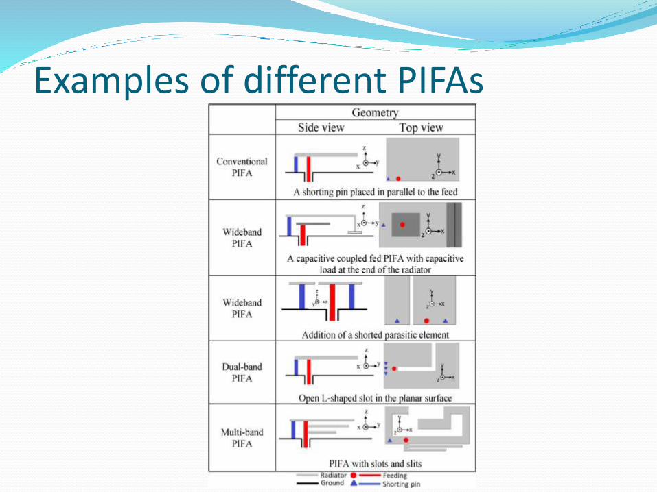
Examples of different PIFAs

These techniques can be used together to produce a practical multiband PIFA, as shown in Fig. below:

Today, many small antennas for wireless portable devices are based on the PIFA design.
PIFAs are particularly useful as embedded antennas for cellular phones owing to their small size and wide bandwidth characteristics.
A recent trend on the development of PIFAs is to print the antennas on the casing of a wireless device. As an example, the plastic cover of a smartphone printed with many conformal antennas is illustrated on next slide.


2. Broadband Shorted Patch Antenna Basic Patch Antenna:
The basic microstrip patch antenna has a dimension slightly less than half-wavelength and an impedance bandwidth of about a few percent of the resonant frequency. The antenna has two effective radiating edges producing a symmetrical radiation pattern with respect to the normal direction of the ground plane.

The major disadvantage of this half-wave patch antenna is that it is difficult, to reduce the size and to increase the impedance bandwidth simultaneously to fulfill practical requirements.
Alternatively, it was found that the basic shorted patch antenna is not only intrinsically smaller in size but also can be improved with much wider impedance bandwidth.
The shorted patch antenna has a patch length near a quarter of a wavelength, which is smaller than the basic patch antenna by 50%.

Simple techniques for increasing the bandwidth of the antenna are shown below.
(a) Basic shorted patch antenna BW=3%.
(b) Stacked shorted patch antenna BW=9.6%.
(c) Shorted patch antenna with L-probe feed BW=39% .
(d) Shorted U-slot patch antenna BW=22.7% .

To further minimize the antenna size and broaden the impedance bandwidth, two major approaches were suggested.
The first one is to generate double or multiple resonances by folding the resonant patch and the other one is to reduce the undesirable feed inductance by employing a “folded patch feed”.
Here, they are reclassified into:
1) upward-folded shorted patch antenna and
2) downward-folded patch antenna.

For the upward-folded type, the antenna can be considered as a combination of two face-to-face shorted patch antennas of different dimensions stacking together as shown in (a) and (b).

In doing so, two different resonances are created. Depending on the separation of the two resonant points which is controlled by the relative sizes of the two portions, the antenna can be operated in two narrow frequency bands or in a single wide frequency band.
The dual-band design, as shown in (a), operates at 1.55 and 2.2 GHz with bandwidth 8% and 10%, respectively.
The single wideband design, as shown in (b), has 29% bandwidth.

The bandwidth of the upward-folded shorted patch antenna can be enhanced to 99% by introducing two L-shaped open slits in the lower patch of the antenna, as depicted in(c).
Alternatively, it was shown that the bandwidth can be increased dramatically to 133% by etching just one L-shaped open slot in the lower patch of the antenna, using a folded patch feed and adjusting the antenna to have larger dimensions, as shown in (d)

The antenna depicted in (e) can be considered as an enhanced version of the shorted U-slot patch antenna, by folding the inner portion of the U-shaped slot downward. The bandwidth can be enhanced to 53%.
The antenna, as depicted in (f), can be considered as a modification of the shorted E-patch antenna by folding the middle arm of the E-shaped patch downward. Similar to the previous design, the required length of the probe feed for this structure is much smaller than that for the original shorted E-patch. This antenna has a wide BW of 73%.

If an application can tolerate an antenna with a larger size and higher profile, the antenna shown in (g) may be chosen. With the introduction of a trapezoidal-shaped slot in the top surface of the downward-folded patch, the antenna exhibits a bandwidth of 104%.
Recently, the design was enhanced into a more symmetrical structure, as shown in (h). It was demonstrated that the two triangular fins and rectangular slot can help to create more resonant points for improving the bandwidth to 125%.

3. Compact Differentially Fed Antennas Small differentially fed antennas are increasingly used
in portable wireless devices.
The dipole and the loop are two notable types of balanced antennas which are commonly used as differentially fed antennas for small wireless devices.
They are simple in structure, low in profile, and easy to fabricate.

Dipole Antenna :A dipole antenna is the simplest and most widely used class of antenna. It consists of two identical conductive elements such as metal wires or rods, which are usually bilaterally symmetrical. The driving current from the transmitter is applied, or for receiving antennas the output signal to the receiver is taken, between the two halves of the antenna. Each side of the feedline to the transmitter or receiver is connected to one of the conductors.

Size Reduction techniques:
The first common technique is to use meandering lines instead of straight wires for the two arms of an electric dipole.
Similarly, the zigzag dipole is another popular solution for antenna miniaturization.
Both the meandering and zigzag designs are simple ways for reducing the dipole size, however, a mismatching problem may occur in some applications.

To solve this problem, a U-matched or T-matched component can be connected across the differential ports of the dipole.

Recently, a new small dipole called the left-hand loaded dipole was proposed.
Although this technique is very effective for size reduction, it is more costly to fabricate the antenna with complex left-hand structures.

Loop antenna: A loop antenna is a radio antenna consisting of a loop (or loops) of wire, tubing, or other electrical conductor with its ends connected to a balanced transmission line. Within this physical description there are two very distinct antenna designs: the small loop (or magnetic loop) with a size much smaller than a wavelength, and the resonant loop antenna with a circumference approximately equal to the wavelength.

For ease of impedance matching and for generating a usable radiation pattern, the circumference of a circular loop antenna should be about one wavelength long which, however, is too large for many portable wireless devices.
So various size reduction techniques are used to reduce the size for use in portable wireless devices:
The most popular size reduction technique for the loop antenna operated at low frequencies is to use a small loop loaded with a variable capacitor.

This technique can shorten significantly the loop circumference to 10% of the operating wavelength but the radiation efficiency of the antenna is drastically reduced owing to the decrease in effective area of radiation and the power dissipation in the capacitor.
Similarly, inductor loaded loop antennas were also proposed. However, these antennas also have disadvantages of low radiation efficiency and narrow impedance bandwidth.

Alternatively, the 3-D folded loop method was developed. Since the total length of the 3-D folded loop antenna is kept at about one wavelength, the antenna has a larger effective area for radiation contributed by the vertical and horizontal portions of the 3-D folded loop.

The data available in show that the 3-D folded loop design not only yields a reasonable antenna gain but also can operate with double resonances.
The drawback of the 3-D folded loop antenna is high fabrication costs, which is expected.The antenna can be used as a handset antenna.
If multiband operation is required, additional resonances can be created by adding a printed monopole.

Small RF modules with differential feed antennas. (a) Rf module with meandering U-matched dipole. (b) RF module with zigzag loop antenna. (c) RFID tag with meandering loop antenna for CD/DVD.

4. Miniature circularly polarized Patch Antennas Circularly Polarized Patch Antennas: It is also possible
to fabricate patch antennas that radiate circularly-polarized waves. One approach is to excite a single square patch using two feeds, with one feed delayed by 90° with respect
to the other.
An alternative is to use a single feed but introduce some sort of asymmetric slot or other feature on the patch, causing the current distribution to be displaced.

A basic CP antenna is not a compact structure. Several size reduction techniques are used.
They can be categorized as:
1) using dielectric substrate to support the patch
2) slot loaded patch
3) slit loaded patch
4) folded patch
5) defected ground plane
6) addition of shorted pins

Employing a dielectric substrate to support the patch is a simple and effective method to reduce the size of a patch antenna. Using a higher value of relative Permittivity Єr can achieve a smaller patch size. However, the bandwidth and gain can be reduced drastically. Expensive material cost is also a concern.

Using slots loaded patch is another common method for patch antenna size reduction. With the presence of slots, the effective current path length on the patch can be extended.
Consequently, the resonance of the patch antenna can be shifted down to a lower frequency. In particular, the cross slot loaded patch antenna has been popularly used for various wireless applications.

Using slit loaded patch is similar in principle to using slot loaded patch for reducing the size of a patch antenna.
This method also increases the current path on the patch and results in size reduction. The slits can be located near the edges or corners of the patch.

To design a small CP patch antenna without a supporting dielectric material, the folded patch technique can be considered. With the addition of vertical plates at the edges of the patch, the effective current path in the patch is increased without the need to increase the projection area of the antenna. This approach has drawbacks of large antenna thickness and high fabrication cost.

Another size reduction technique is to use a defected ground plane for the patch antenna. By cutting some slots in the ground plane, the effective current path in the ground plane can be increased. The weakness of the method is high back radiation contributed by the slots in the ground plane.

Inspired by the development of the compact shorted quarter-wave CP patch antenna, the shorted elliptical CP patch antenna, and the miniature antenna composed of four IFA elements, a compact CP patch antenna with four virtually shorting pins was invented. This method of using virtually shorting pins was found to be very effective to reduce the size of a CP patch antenna.

Although many techniques are available to reduce the size of a CP antenna substantially, the resulting radiation pattern of the antenna may not be acceptable in applications. For examples, the small antennas described either have high in back radiation or with an asymmetric radiation pattern.
They are not suitable for the mobile satellite communications that requires a broadside radiation pattern with wide beam width, acceptable gain, and good axial ratio. Therefore, it is necessary to check the radiation patterns of CP patch antennas.

Three-dimensional radiation patterns. (a) Truncated patch antenna. (b) Cross-slot patch antenna. (c) Virtually shorted patch antenna.
They have the same ground plane size, substrate of relative permittivity of Єr=4, and antenna thickness.

References Small Antennas in Wireless Communications
Complexities and developments in small antennas for wireless communications are discussed in this paper including context, physical insight, and perspective. By Hang Wong, Member IEEE, Kwai-Man Luk, Fellow IEEE, Chi Hou Chan, Fellow IEEE, Quan Xue, Fellow IEEE, Kwok Kan So, Member IEEE, and Hau Wah Lai, Member IEEE.
en.wikipedia.org
http://www.antenna-theory.com/


![[PPT]SMART ANTENNAS FOR WIRELESS …dsp.ucsd.edu/~liwen/ECE287A/intro.ppt · Web viewTitle SMART ANTENNAS FOR WIRELESS COMMUNICATION Author Bhaskar Rao Last modified by Bhaskar Rao](https://img.dokumen.tips/doc/110x75/5ab076467f8b9a6b468b4c87/pptsmart-antennas-for-wireless-dspucsdeduliwenece287aintropptweb-viewtitle.jpg)


![InTech-Microstrip Antennas for Mobile Wireless Communication Systems[1]](https://img.dokumen.tips/doc/110x75/577d1de01a28ab4e1e8d28a5/intech-microstrip-antennas-for-mobile-wireless-communication-systems1.jpg)


