Embed Size (px)
Citation preview

AJ2
Synergy Engineers
CFB Boiler Assessment
Site Inspection Guidelines & Protocol
Compiled and Edited
By
José Agustín González

AJ2
PROJECT MANAGEMENT
QUALITY SYSTEMS ENGINEERING
Synergy Engineers
JOSÉ AGUSTÍN GONZÁLEZ II
SUMMARY OF DOCUMENT REVISIONS
Rev. Date Revised Section Revised
Revision Description
00 21/12/2016 N/A Internal issue of document
00A 30/12/2016 N/A Issued for Internal Review and Edition
00 03/01/2017 N/A Issued with new file name - FROM: Inspection.XC-1306.86-M8.CFB.Peru.Rev.00 – TO: Site.Inspection.XC-1306.86-M8.CFB.Peru.Rev.00
01 05/01/2017 4 & 5 Include missing internal inspection sections and transfer sections previously included in section 5 onto 4
01A 09/01/2017 N/A Document´s Properties
02 16/01/2017 6 Section 6 Safety added to the document thus improving the site inspection guidelines
DOCUMENT´S PROPERTIES
Prepared by José Agustín González Engineering & Systems Integration
Reviewed by Alberto Balarezo Construction and Commissioning
Approved by Joel González Morante Planning & Control
Date of Creation Monday, January 16, 2017
Saved Date Wednesday, January 18, 2017
Number of Words 22913 Words
File Name Site.Inspection.XC-1306.86-M8.CFB.Peru.Rev.02
File Size 5882 Kilobytes 6 Megabytes

AJ2
PROJECT MANAGEMENT
QUALITY SYSTEMS ENGINEERING
Synergy Engineers
JOSÉ AGUSTÍN GONZÁLEZ III
TABLE OF CONTENT
1 BOILERS INSPECTION ................................................................................................................................... 7
2 CIRCULATING FLUIDIZED BED BOILERS ..................................................................................................... 8
2.1 CFB BOILER GENERAL ARRANGEMENT.............................................................................................. 9
2.1.1 FLUE GAS STREAM .............................................................................................................................. 11
2.1.2 SOLID STREAM ..................................................................................................................................... 11
2.1.3 WATER – STEAM CIRCUIT ................................................................................................................... 12
2.1.4 ECONOMIZER ....................................................................................................................................... 12
2.1.5 EVAPORATORS .................................................................................................................................... 13
2.1.6 SUPER-HEATERS AND RE-HEATERS ................................................................................................. 13
2.2 TYPES OF CFB BOILERS ..................................................................................................................... 14
2.2.1 BOILERS WITHOUT BUBBLING BED HEAT EXCHANGERS ............................................................... 15
2.2.2 BOILERS WITH BUBBLING FLUIDIZED BED HEAT EXCHANGER ..................................................... 16
2.2.3 BOILERS WITH INERTIAL OR IMPACT SEPARATORS ....................................................................... 16
2.2.4 BOILERS WITH VERTICAL, NONCIRCULAR CYCLONES ................................................................... 17
2.2.5 OTHER TYPES ...................................................................................................................................... 17
3 BOILER DEGRADATION MECHANISMS ...................................................................................................... 18
3.1 CORROSION .......................................................................................................................................... 18
3.2 EROSION ............................................................................................................................................... 18
3.3 FATIGUE ................................................................................................................................................ 18
3.4 OVER-HEATING .................................................................................................................................... 19
3.5 HYDROGEN DAMAGE .......................................................................................................................... 19
3.6 VIBRATION ............................................................................................................................................ 19
4 CONDITION ASSESSMENT EXAMINATION METHODS.............................................................................. 20
4.1 NON-DESTRUCTIVE EXAMINATIONS ................................................................................................. 22
4.1.1 VISUAL ................................................................................................................................................... 22
4.1.2 MAGNETIC PARTICLES ........................................................................................................................ 22
4.1.3 LIQUID PENETRANT ............................................................................................................................. 22
4.1.4 ULTRASONIC ......................................................................................................................................... 23
4.1.4.1 ULTRASONIC THICKNESS TESTING ............................................................................................... 23
4.1.4.2 ULTRASONIC OXIDE MEASUREMENT ............................................................................................ 23
4.1.4.3 ULTRASONIC MEASUREMENT OF INTERNAL TUBE DAMAGE .................................................... 25
4.1.4.4 IMMERSION ULTRASONIC TESTING............................................................................................... 25
4.1.4.5 SHEER WAVE ULTRASONIC TESTING ........................................................................................... 25
4.1.4.6 TIME OF FLIGHT DEFRACTION (TOFD) .......................................................................................... 26
4.1.5 EDDY CURRENT ................................................................................................................................... 26
4.1.6 RADIOGRAPHY ..................................................................................................................................... 26
4.1.7 NUCLEAR FLUORESCENCE ................................................................................................................ 27
4.1.8 ELECTROMAGNETIC ACOUSTICS ...................................................................................................... 27

AJ2
PROJECT MANAGEMENT
QUALITY SYSTEMS ENGINEERING
Synergy Engineers
JOSÉ AGUSTÍN GONZÁLEZ IV
4.1.9 ACOUSTICS ........................................................................................................................................... 29
4.1.10 ACOUSTIC EMISSIONS .................................................................................................................... 30
4.1.11 METALLOGRAPHIC REPLICATION .................................................................................................. 30
4.1.12 STRAIN MEASUREMENT .................................................................................................................. 30
4.1.13 TEMPERATURE MEASUREMENT .................................................................................................... 30
4.2 DESTRUCTIVE EXAMINATIONS .......................................................................................................... 31
4.2.1 TUBE SAMPLES .................................................................................................................................... 31
4.2.2 BOAT SAMPLES .................................................................................................................................... 31
4.3 ADVANCES IN NON-DESTRUCTIVE EXAMINATIONS ........................................................................ 31
5 SITE INSPECTION OF BOILER COMPONENTS AND AUXILIARIES .......................................................... 32
5.1 EXTERNAL BOILER INSPECTION ........................................................................................................ 32
5.1.1 LADDERS, STAIRWAYS AND PLATFORMS ........................................................................................ 32
5.1.1.1 CRACKS ............................................................................................................................................. 32
5.1.1.2 TIGHTNESS OF BOLTS ..................................................................................................................... 33
5.1.1.3 CONDITION OF PAINT OR GALVANIZED MATERIAL ..................................................................... 33
5.1.1.4 WEAR ON LADDER RUNGS AND STAIR TREADS. ......................................................................... 33
5.1.1.5 SECURITY OF HANDRAILS .............................................................................................................. 33
5.1.1.6 THE CONDITION OF FLOORING ...................................................................................................... 33
5.1.2 FANS ...................................................................................................................................................... 33
5.1.3 AIR DUCTS AND FLUE GAS DUCTS .................................................................................................... 33
5.1.4 SUPPORT STRUCTURE AND BOILER CASING .................................................................................. 33
5.1.5 STACK .................................................................................................................................................... 34
5.1.6 BOILER PIPING ..................................................................................................................................... 35
5.1.7 INSTRUMENTATION ............................................................................................................................. 35
5.1.8 PAINT AND INSULATION ...................................................................................................................... 35
5.2 INTERNAL BOILER INSPECTION ......................................................................................................... 35
5.2.1 SAFE ENTRY ......................................................................................................................................... 36
5.2.2 REFRACTORY ....................................................................................................................................... 36
5.2.3 STEAM DRUM ........................................................................................................................................ 37
5.2.4 BOILER TUBING .................................................................................................................................... 37
5.2.4.1 STEAM-COOLED ............................................................................................................................... 37
5.2.4.2 WATER-COOLED............................................................................................................................... 38
5.2.5 RISERS .................................................................................................................................................. 38
5.2.6 HEADERS .............................................................................................................................................. 38
5.2.6.1 HIGH TEMPERATURE ....................................................................................................................... 38
5.2.6.2 LOW TEMPERATURE........................................................................................................................ 41
5.2.7 ATTEMPERATORS ................................................................................................................................ 41
5.2.8 HIGH TEMPERATURE PIPING .............................................................................................................. 43
5.2.8.1 DAMAGE MECHANISMS ................................................................................................................... 43
5.2.8.2 OVERALL EVALUATION PROGRAM ................................................................................................ 43

AJ2
PROJECT MANAGEMENT
QUALITY SYSTEMS ENGINEERING
Synergy Engineers
JOSÉ AGUSTÍN GONZÁLEZ V
5.2.9 DETAILED EVALUATION PROGRAM ................................................................................................... 43
5.2.9.1 Phase I................................................................................................................................................ 43
5.2.9.2 Phase II ............................................................................................................................................... 44
5.2.10 TYPICAL FAILURES .......................................................................................................................... 45
5.2.11 LOW TEMPERATURE PIPING .......................................................................................................... 45
5.2.11.1 TYPICAL FAILURES ...................................................................................................................... 45
5.2.12 TUBULAR AIR HEATERS .................................................................................................................. 46
5.3 BOILER SETTINGS ................................................................................................................................ 46
5.3.1 DESIGN REQUIREMENTS .................................................................................................................... 47
5.3.2 TUBE WALL ENCLOSURES .................................................................................................................. 48
5.3.2.1 MEMBRANE TUBES .......................................................................................................................... 48
5.3.2.2 MEMBRANE TUBES WITH REFRACTORY LINING.......................................................................... 49
5.3.2.3 FLAT STUD TUBE WALLS ................................................................................................................. 49
5.3.2.4 TANGENT TUBE WALL ..................................................................................................................... 51
5.3.2.5 FLAT STUD AND TANGENT TUBE WALL UPGRADES ................................................................... 52
5.3.3 CASING ENCLOSURES ........................................................................................................................ 52
5.3.3.1 HOPPER ............................................................................................................................................. 52
5.3.3.2 WIND-BOX ......................................................................................................................................... 53
5.3.3.3 TEMPERING GAS PLENUM .............................................................................................................. 53
5.3.3.4 PENTHOUSE ..................................................................................................................................... 53
6 SAFETY.......................................................................................................................................................... 54
6.1 EXPLOSIONS ......................................................................................................................................... 54
6.2 IMPLOSIONS ......................................................................................................................................... 55
7 INSPECTION FORM TEMPLATE .................................................................................................................. 56
7.1 EXTERNAL BOILER INSPECTION ........................................................................................................ 58
7.2 INTERNAL BOILER INSPECTION ......................................................................................................... 83
8 RELIABLE INFORMATION IS KEY TO A RELIABLE ASSESSMENT ........................................................... 99
9 CFB Boilers – Reheat and Non-reheat ......................................................................................................... 100

AJ2
PROJECT MANAGEMENT
QUALITY SYSTEMS ENGINEERING
Synergy Engineers
JOSÉ AGUSTÍN GONZÁLEZ VI
TABLE OF FIGURES
Figure 1 – Non-reheat Circulating fluidized bed boiler major components ............................................................... 8
Figure 2 – General arrangement of a typical circulating fluidized bed boiler ............................................................ 9
Figure 3 – Air and feed circuit of a CFB boiler with an external heat exchanger .................................................... 10
Figure 4 – Water and Steam circuit of a CFB boiler without an external heat exchanger ....................................... 12
Figure 5 – Arrangement of a CFB boiler with impact separators ............................................................................ 14
Figure 6 – CFB boiler with a vertical non-circular cyclone ...................................................................................... 15
Figure 7 – Application of steel, refractory, and expansion joints to a CFB boiler .................................................... 16
Figure 8 – A novel design of CFB boiler with central multi-entry cyclone ............................................................... 17
Figure 9 – Three phase (levels) of boiler damage assessment .............................................................................. 21
Figure 10 – Steam side oxide scale on ID surface ................................................................................................. 24
Figure 11 – Typical ultrasonic signal response ....................................................................................................... 24
Figure 12 - Sheer wave technique for detecting hydrogen damage ....................................................................... 26
Figure 13 – Basic principles of EMAT operation ..................................................................................................... 28
Figure 14 – B&W´s Fast-Scanning Thickness Gage (FST-GAGE®) ....................................................................... 28
Figure 15 - header locations susceptible of cracking .............................................................................................. 39
Figure 16 - Steam temperature variation in a header ............................................................................................. 40
Figure 17 - Super-heater tube leg temperatures vary with load .............................................................................. 40
Figure 18 - Large ligament cracks on header ID. ................................................................................................... 41
Figure 19 - Typical attemperator assembly ............................................................................................................ 42
Figure 20 - Failed attemperator spray head ........................................................................................................... 42
Figure 21 - Acoustic Ranger® schematic ................................................................................................................ 46
Figure 22 – Membrane wall construction ................................................................................................................ 48
Figure 23 – Fully studded membrane wall .............................................................................................................. 49
Figure 24 – Flat stud tube wall construction with inner casing shown .................................................................... 50
Figure 25 – Tangent tube wall construction with outer casing shown ..................................................................... 51
Figure 26 – Casing attachment to membrane wall ................................................................................................. 51
Figure 27 – Tangent tubes with closure rods .......................................................................................................... 52
Figure 28 – Widely spaced tubes with flat studs and closure bars ......................................................................... 52
Figure 29 – Tie bar and buck-stay arrangement at corner of furnace ..................................................................... 55
Figure 30 – CFB Boilers Reheat and Non-reheat ................................................................................................. 100

AJ2
PROJECT MANAGEMENT
QUALITY SYSTEMS ENGINEERING
Synergy Engineers
JOSÉ AGUSTÍN GONZÁLEZ Page 7 de 100
1 BOILERS INSPECTION
Inspections are done to determine the amount of maintenance required to have the equipment operate
properly, until the next turnaround. Boilers should be inspected at least every two years. Inspection
intervals are based on service and experience.
Inspection is not an exact science and requires the use of judgment and experience as well as science.
Records should be reviewed before an inspection, to become thoroughly familiar with the equipment. This
review should result in identifying expected problems and planning areas of emphasis for the planned
inspection. The following records that should be checked are as follows:
1. Original Design Drawings
2. Piping and Instrumentation Diagrams (P&IDs)
3. E & I Single Line Diagrams
4. DCS (Distributed Control System)
5. Boiler Log
6. Maintenance Records
7. Safety Instruction Sheets (SIS)
8. Hydrostatic Test Diagram
9. Previous hydrostatic test results
The original design drawings and the P&IDs provide information on the pressure and temperature of the
original design. The original design drawings indicate inspection points, with notes on inspection
procedures. These drawings also contain notes on how to access equipment. The P&IDs should also
show all pipe sizes, materials of construction, vent and drain locations, and blind. They also provide
material specifications and original thickness of equipment.
The boiler log provides a record of each inspection, maintenance check, and notes on the equipment.
These notes are necessary to prepare for inspection. The maintenance records indicate conditions found
in a previous inspection that required maintenance. The Safety Instruction Sheets (SIS) provides operating
pressure and temperature information, and pressure test targets. It also contains the retirement thickness
on critical piping. The hydraulic test diagram is a line drawing showing blinds, piping layout, and location
of pressure test connections. The test diagram will specify the relief valve size, set pressure, and location.
Previous hydraulic test results indicate problem areas from previous inspections.

AJ2
PROJECT MANAGEMENT
QUALITY SYSTEMS ENGINEERING
Synergy Engineers
JOSÉ AGUSTÍN GONZÁLEZ Page 8 de 100
2 CIRCULATING FLUIDIZED BED BOILERS
The circulating fluidized bed (CFB) boiler is a member of the fluidized bed boiler family. It has gained
popularity, especially in the electric power-generation market, for its several practical advantages (Figure
1 – Non-reheat Circulating fluidized bed boiler major components), such as efficient operation and
minimum effect on the environment. Although it entered the market only in the 1980s, CFB technology is
well beyond its initial stage of development. The technology has matured through successful operation in
hundreds of units of capacities ranging from 1 MWe to 340 MWe (until 2005). The problems of the first
generation have been solved and CFB is now considered to be a mature technology for atmospheric-
pressure units. Its design methodology, however, is not as well-established as that of pulverized coal-fired
boilers. Many aspects of its design are still based on rules of thumb. The present chapter describes
different aspects of the circulating fluidized bed boiler including a brief outline of a design approach.
Figure 1 – Non-reheat Circulating fluidized bed boiler major components

AJ2
PROJECT MANAGEMENT
QUALITY SYSTEMS ENGINEERING
Synergy Engineers
JOSÉ AGUSTÍN GONZÁLEZ Page 9 de 100
2.1 CFB BOILER GENERAL ARRANGEMENT
A CFB boiler (See Figure 1 – Non-reheat Circulating fluidized bed boiler major components) may be
divided into two sections:
1. The CFB loop and the convective or back-pass section of the boiler (Figure 2 – General arrangement
of a typical circulating fluidized bed boiler). The CFB loop consists of the following items making up
the external solid recirculation system.
1. Furnace or CFB riser
2. Gas–solid separation (cyclone)
3. Solid recycle system (loop-seal)
4. External heat exchanger (optional)
Figure 2 – General arrangement of a typical circulating fluidized bed boiler
Whereas Figure 2 – General arrangement of a typical circulating fluidized bed boiler shows the general
arrangement of a typical CFB boiler without the external heat exchanger; Figure 3 – Air and feed circuit of
a CFB boiler with an external heat exchanger shows the same for one with the heat exchanger.
2. The back-pass is comprised of:
1. Super-heater
2. Re-heater
3. Economizer
4. Air heater

AJ2
PROJECT MANAGEMENT
QUALITY SYSTEMS ENGINEERING
Synergy Engineers
JOSÉ AGUSTÍN GONZÁLEZ Page 10 de 100
Figure 3 – Air and feed circuit of a CFB boiler with an external heat exchanger
The following section describes the working of the boiler, tracing the path of air, gas, solids and water
through it.
The primary air fan delivers air at high pressure (10 to 20 kPa). This air is preheated in the air preheater
of the boiler and then enters the furnace through the air distributor grate at the bottom of the furnace.
The secondary air fan delivers air, also preheated in the air preheater, at a relatively low pressure (5 to
15 kPa). It is then injected into the bed through a series of ports located around the periphery of the
furnace and at a height above the lower tapered section of the bed. In some boilers, the secondary air
provides air to the start-up burner as well as to the tertiary air at a still higher level, if needed. The
secondary air fan may also provide air to the fuel feeder to facilitate the smooth flow of fuel into the furnace.
Loop-seal blowers deliver the smallest quantity of air but at the highest pressure. This air directly enters
the loop-seals through air distribution grids. Unlike primary and secondary air, the loop-seal air is not
heated.

AJ2
PROJECT MANAGEMENT
QUALITY SYSTEMS ENGINEERING
Synergy Engineers
JOSÉ AGUSTÍN GONZÁLEZ Page 11 de 100
2.1.1 FLUE GAS STREAM
Generally, only one suction fan is used to handle the flue gas in a CFB boiler. This fan, called induced
draft (ID) fan, creates suction in the system to draw flue gas from the boiler and through the dust control
or any other gas emission-control equipment. The suction head of the ID fan is designed to have a
balanced draft in the air/flue gas system with zero (or atmospheric) pressure at the mid or the top section
of the furnace. This helps keep the boiler-house clean and at the same time optimizes the power
consumption by the ID fan.
2.1.2 SOLID STREAM
Fuel from the bunker drops on to a belt or some other type of feeder, which then feeds measured quantities
of fuel into the fuel chute. In most large CFB boilers, the fuel chute feeds the fuel into the loop-seal’s
inclined pipe (Figure 3 – Air and feed circuit of a CFB boiler with an external heat exchanger). Here, the
fuel mixes with hot solids recirculating around the CFB loop, and therefore enters the bed better dispersed.
Other boilers either take the fuel directly into the lower section of the bed through the front wall or use
another conveyor to take it around the furnace for sidewall feeding.
The sorbent is generally finer than the fuel, so it is carried by conveying air and injected into the bed
through several feed injection points. As sorbents react very slowly, the location of their feed points is not
as critical as that for the fast-burning fuel.
The ash or spent sorbent is drained from the boiler through the following points:
1. Bed drain
2. Fly ash collection hopper under the fabric filter or electrostatic precipitator
3. Economizer or back-pass hopper
In some cases, ash is also drained partially from the external heat exchanger. In the case of a coarse bed
drain, the ash is cooled by air or water before it is disposed of. The fly ash, being relatively cold, can be
disposed of without cooling. Its particles are generally smaller than 100 mm with a mean size of 30 mm
and are, therefore, easily carried pneumatically into a fly ash silo, where they are hauled away by truck or
rail wagon as necessary.
The mixture of fuel, ash, and sorbents circulate around the CFB loop. Particles, coarser than the cyclone
cut-off size, are captured in the cyclone and recycled near the base of the furnace. Finer solid residues
like ash or spent sorbents, generated during combustion and desulfurization, escape through the
cyclones. These are collected by the fabric filter or electrostatic precipitator located further downstream.
AJ2
PROJECT MANAGEMENT
QUALITY SYSTEMS ENGINEERING
Synergy Engineers
JOSÉ AGUSTÍN GONZÁLEZ Page 12 de 100
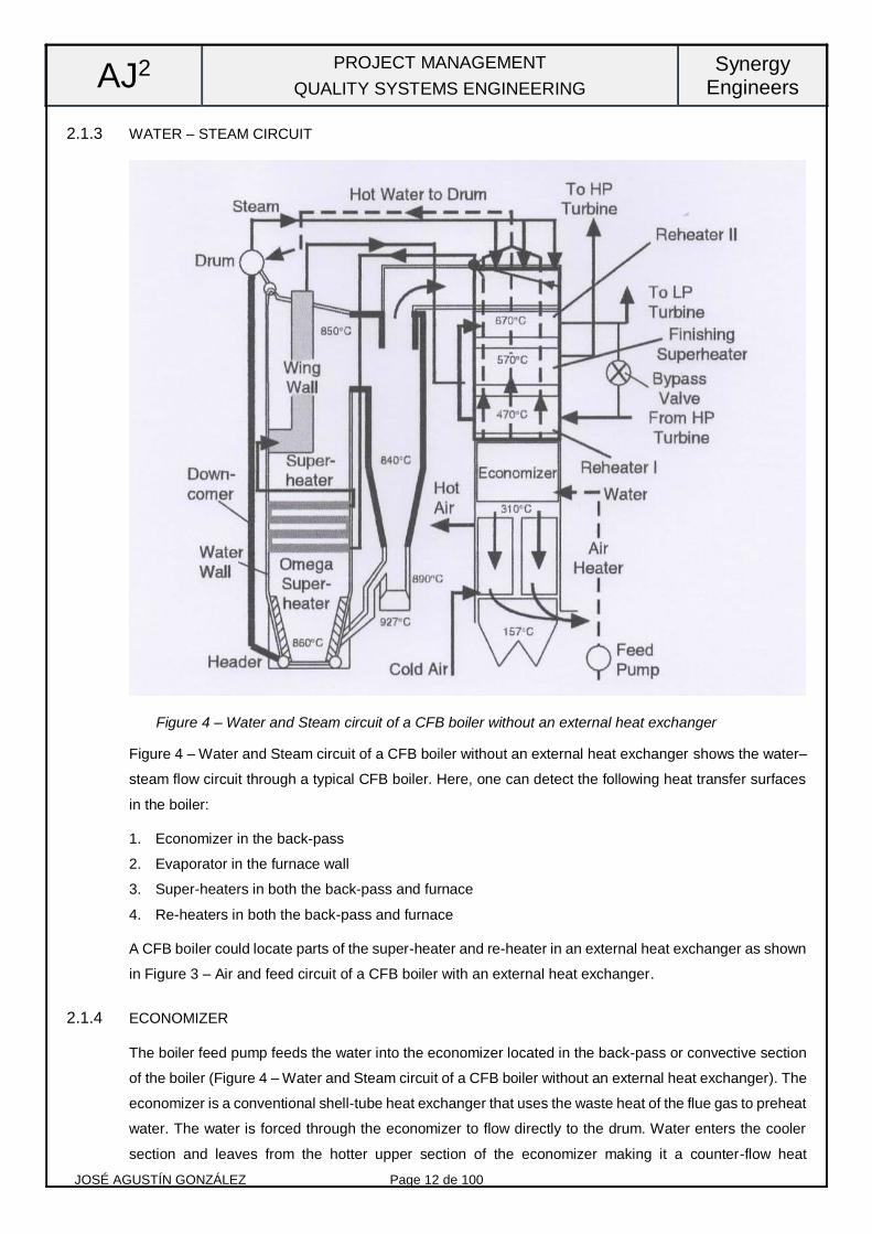
2.1.3 WATER – STEAM CIRCUIT
Figure 4 – Water and Steam circuit of a CFB boiler without an external heat exchanger
Figure 4 – Water and Steam circuit of a CFB boiler without an external heat exchanger shows the water–
steam flow circuit through a typical CFB boiler. Here, one can detect the following heat transfer surfaces
in the boiler:
1. Economizer in the back-pass
2. Evaporator in the furnace wall
3. Super-heaters in both the back-pass and furnace
4. Re-heaters in both the back-pass and furnace
A CFB boiler could locate parts of the super-heater and re-heater in an external heat exchanger as shown
in Figure 3 – Air and feed circuit of a CFB boiler with an external heat exchanger.
2.1.4 ECONOMIZER
The boiler feed pump feeds the water into the economizer located in the back-pass or convective section
of the boiler (Figure 4 – Water and Steam circuit of a CFB boiler without an external heat exchanger). The
economizer is a conventional shell-tube heat exchanger that uses the waste heat of the flue gas to preheat
water. The water is forced through the economizer to flow directly to the drum. Water enters the cooler
section and leaves from the hotter upper section of the economizer making it a counter-flow heat

AJ2
PROJECT MANAGEMENT
QUALITY SYSTEMS ENGINEERING
Synergy Engineers
JOSÉ AGUSTÍN GONZÁLEZ Page 13 de 100
exchanger. The temperature of the water leaving the economizer is generally kept at least 288C below
the saturation temperature of the water to ensure good circulation. Some high-performance boilers allow
steam formation, but considering the possibility of non-uniform flow distribution between tubes, flow
instabilities and other factors the rise in enthalpy in the economizer should be guided by the following
equation (Stultz and Kitto, 1992):
Equation 1
𝐻2 − 𝐻1 = 2
3(𝐻𝑓 − 𝐻1)
Where H1, H2, and Hf are enthalpies of water entering the economizer, leaving the economizer and at
saturated condition at the economizer outlet pressure, respectively.
The water velocity through the economizer is typically in the range of 600 to 800 kg/m2s and gas velocity
is in the range of 7 to 15 m/s.
2.1.5 EVAPORATORS
In a typical subcritical boiler, the water flows down large-diameter unheated pipes (known as down-
comers) into distributing manifolds called headers. The header distributes water amongst vertical tubes
rising along the walls of the furnace. Water rises through these tubes and hence they are called riser, or
water wall tubes. To make an airtight enclosure around the furnace, these tubes are generally welded
together by means of fins between them in the form of panels.
As the water rises up the tubes it absorbs heat from the furnace, converting part of it into steam. Hot water,
carrying steam bubbles, leaves the top of the water wall panels and is collected in headers, which in turn
carry it to the steam drum. Steam is separated from the water in the drum, which mixes with fresh water
from the economizer and flows down through the down-comer and into the riser for heating again.
Sometimes four walls of the furnace cannot provide sufficient surface area to carry the entire evaporative
load of the boiler. Additional surfaces are provided in the form of wing walls in the furnace (Figure 4 –
Water and Steam circuit of a CFB boiler without an external heat exchanger) or in the form of bank tubes
downstream of the furnace to take this load.
2.1.6 SUPER-HEATERS AND RE-HEATERS
Figure 4 – Water and Steam circuit of a CFB boiler without an external heat exchanger shows the
arrangement of re-heaters and super-heaters in a typical CFB boiler. Saturated steam from the drum flows
through a set of tube panels forming the walls of the back-pass. Then it goes to the omega super-heater
panels inside the furnace. These tubes are formed from a special steel section that, when joined, gives a
flat vertical surface to minimize the erosion potential. The partially-heated steam then rises up through
wing wall tubes as shown (Figure 4 – Water and Steam circuit of a CFB boiler without an external heat
exchanger) and passes through the final super-heater located in the back pass. Such a complex back-
and-forth tube arrangement helps minimize the cost of tubes while minimizing any risk of tube overheating.
Steam temperature can be controlled by spraying water into the steam at appropriate locations.

AJ2
PROJECT MANAGEMENT
QUALITY SYSTEMS ENGINEERING
Synergy Engineers
JOSÉ AGUSTÍN GONZÁLEZ Page 14 de 100
Low pressure steam enters the re-heater section immediately upstream of the economizer (Figure 4 –
Water and Steam circuit of a CFB boiler without an external heat exchanger). It then passes through the
final re-heater section upstream of the final super-heater. One may use a bypass valve between the entry
and exit of the re-heater section to control the steam temperature.
2.2 TYPES OF CFB BOILERS
Numerous designs of CFB boilers are available in the market, some of which are more common than
others. The following are four major types of CFB boiler designs:
1. Boilers with vertical, hot cyclones with or without in-furnace heating surfaces (Figure 2 – General
arrangement of a typical circulating fluidized bed boiler)
2. Boilers as above, with bubbling fluidized bed heat exchanger parallel in the CFB loop (Figure 3 – Air
and feed circuit of a CFB boiler with an external heat exchanger)
3. Boilers with impact or inertial-type separators (Figure 5 – Arrangement of a CFB boiler with impact
separators)
4. Boilers with vertical, noncircular, cooled cyclones (Figure 6 – CFB boiler with a vertical non-circular
cyclone)
Figure 5 – Arrangement of a CFB boiler with impact separators

AJ2
PROJECT MANAGEMENT
QUALITY SYSTEMS ENGINEERING
Synergy Engineers
JOSÉ AGUSTÍN GONZÁLEZ Page 15 de 100
Figure 6 – CFB boiler with a vertical non-circular cyclone
2.2.1 BOILERS WITHOUT BUBBLING BED HEAT EXCHANGERS
This is the most popular type and belongs to the first generation CFB boilers that entered the market in
the 1980s. The furnace is connected by way of an expansion joint to a thick, refractory-lined, vertical, hot
cyclone, which feeds the collected solids to a loop-seal. The loop-seal returns the solids to the furnace.
Several expansion joints are used at different sections to compensate for the differential expansion
between the cooled furnace and uncooled cyclone-loop-seal circuit as shown by Figure 7 – Application of
steel, refractory, and expansion joints to a CFB boiler. Following types of in-furnace surfaces are used if
needed to meet the demand for required furnace heat absorption:
1. Wing wall (also called platen) (Figure 2 – General arrangement of a typical circulating fluidized bed
boiler)
2. Omega tube panel (Figure 3 – Air and feed circuit of a CFB boiler with an external heat exchanger)
3. Division wall

AJ2
PROJECT MANAGEMENT
QUALITY SYSTEMS ENGINEERING
Synergy Engineers
JOSÉ AGUSTÍN GONZÁLEZ Page 16 de 100
Figure 7 – Application of steel, refractory, and expansion joints to a CFB boiler
2.2.2 BOILERS WITH BUBBLING FLUIDIZED BED HEAT EXCHANGER
The flue gas needs to be cooled down to the required temperature (800º to 900º C) before it leaves the
CFB loop. In large boilers (.100 MWe) the furnace walls alone cannot absorb this heat, so additional
surfaces like wing walls are required. Such surfaces do not give the flexibility of control of heat absorption,
which may be required for partial load operation or for burning alternative types of fuel. For this reason, a
bubbling fluidized bed heat exchanger as shown in Figure 3 – Air and feed circuit of a CFB boiler with an
external heat exchanger is used in the CFB loop in this type of boiler. It is placed in parallel to the solid
recycle line between the loop-seal and furnace. A part of the solid stream from the loop-seal is diverted
through the bubbling fluidized bed heat exchanger. Boiler heat-absorbing tubes are located in the fluidized
bed to absorb heat from the hot solids circulating through it. By regulating the amount of solids diverted
through it, solid flow through the heat exchanger is easily controlled. Two type bubbling fluidized beds are
used:
1. External heat exchanger located outside the furnace (Figure 3 – Air and feed circuit of a CFB boiler
with an external heat exchanger)
2. Internal heat exchanger located in the furnace.
2.2.3 BOILERS WITH INERTIAL OR IMPACT SEPARATORS
In order to avoid the high cost of hot cyclones an alternative type of gas–solid separator is used by this
type of CFB boiler as shown in Figure 5 – Arrangement of a CFB boiler with impact separators. Here, the
solids are separated through impact against a row of U-shaped flow barriers. Such separators are located

AJ2
PROJECT MANAGEMENT
QUALITY SYSTEMS ENGINEERING
Synergy Engineers
JOSÉ AGUSTÍN GONZÁLEZ Page 17 de 100
partially in the furnace and partially outside it. They are not as efficient as centrifugal-type cyclones, so an
additional multi-clone or other type of gas–solid separator is required downstream of the back-pass. Solids
from these separators are also recycled to the furnace. Compactness is a major feature of such boilers.
2.2.4 BOILERS WITH VERTICAL, NONCIRCULAR CYCLONES
This type of boiler is also known as compact design. Here, a geometric-shaped (square or octagonal)
separator chamber is formed by boiler tubes covered with a thin refractory (Figure 6 – CFB boiler with a
vertical non-circular cyclone). Circular gas exits are located on the roof of these chambers. Gas–solid
suspension from the furnace is made to enter the separator chamber through tangential entry points. Such
entries create horizontal vortices, which separate the solids in the chamber and allow the gas to leave
from the top.
2.2.5 OTHER TYPES
In addition to the above, many of other types of CFB boilers are available in the market and are generally
used in smaller-sized units. An important type is the innovative Cymicq design shown in Figure 8 – A novel
design of CFB boiler with central multi-entry cyclone. Here the gas–solid separator and the standpipe are
located in the center of the furnace, with risers around it. Gas–solid suspension enters the central cyclone
through a number of tangential vanes, forming a vortex. The solids drop into the central standpipe while
gas leaves from the top. The collected solids move to the riser through openings at the bottom of the
standpipe as shown in Figure 8 – A novel design of CFB boiler with central multi-entry cyclone. This design
is very compact and needs less refractory because it makes greatest use of heating surfaces. Large
boilers can be built with multiple central tubes in a rectangular riser chamber.
Figure 8 – A novel design of CFB boiler with central multi-entry cyclone

AJ2
PROJECT MANAGEMENT
QUALITY SYSTEMS ENGINEERING
Synergy Engineers
JOSÉ AGUSTÍN GONZÁLEZ Page 18 de 100
3 BOILER DEGRADATION MECHANISMS
3.1 CORROSION
Corrosion occurs inside and outside the tubes, pipes, drums and headers of these lower temperature
components. Internal corrosion is usually associated with the boiler water, contaminants in the water, and
improper chemical cleaning or poor storage procedures. External corrosion can be caused by corrosive
combustion products, a reducing atmosphere in the furnace, moisture between insulation and a
component, and acid formed on components in the colder flue gas zones when the temperature reaches
the acid dew point. Corrosion results in wall metal loss. This wall thinning raises the local stresses of the
component and can lead to leaks or component failure.
Corrosion may also be accelerated by the thermal fatigue stresses associated with startup and shutdown
cycles. Furnace wall tubes, in areas of high structural restraint or high heat flux, often contain internal
longitudinal or external circumferential or longitudinal corrosion fatigue cracks in cycled units.
Corrosion fatigue can occur in the steam drum around rolled tube joints. The residual stresses from the
tube rolling process are additive to the welding and operating pressure stresses. Corrosion from chemical
cleaning and water chemistry upsets acts on this highly stressed area to produce cracking around the seal
weld or the tube hole. Extensive cracking can require drum replacement.
3.2 EROSION
Erosion of boiler components is a function of the percent ash in the fuel, ash composition, and local gas
velocity or soot-blower activity. Changing fuels to a high-ash western United States (U.S.) fuel may lead
to more erosion, slagging and fouling problems.
Changing fuels might also require a change in the lower temperature convection pass elements to
accommodate higher fouling and erosion. The tube wall loss associated with erosion weakens the
component and makes it more likely to fail under normal thermal and pressure stresses. Erosion is
common near soot-blowers; on the leading edges of economizers, super-heaters and re-heaters; and
where there are vortices or around eddies in the flue gas at changes in gas velocity or direction.
Such changes are caused by closely spaced tube surfaces, slag deposits, or other obstructions including
extended surfaces and staggered tube arrangements.
3.3 FATIGUE
The thermal stresses from temperature differentials that develop between components during boiler
startup and shutdown can lead to fatigue cracks. These cracks can develop at tube or pipe bends; at tube-
to-header, pipe-to-drum, fitting-to-tube, and support attachment welds; and at other areas of stress
concentration. Smaller, lower temperature boilers are less prone to fatigue failures because the thermal
differentials are lower and operate over small distances in these units. As unit size and steam temperature
increase, the potential for thermal stresses and the resulting fatigue cracking also rises.

AJ2
PROJECT MANAGEMENT
QUALITY SYSTEMS ENGINEERING
Synergy Engineers
JOSÉ AGUSTÍN GONZÁLEZ Page 19 de 100
3.4 OVER-HEATING
Overheating is generally a problem that occurs early in the life of the plant and can often result in tube
ruptures. These problems may go undetected until a tube failure occurs. Overheating attributable to
operation is generally resolved during the early stages of boiler life. Other problems regarding overheating
may be difficult to ascertain, and specialized boiler performance testing is generally required to identify
the source and determine corrective actions.
In spite of these aging mechanisms, low temperature components are normally expected to be replaced
after more than two decades without major overhauls unless the unit burns a corrosive fuel, burns fuel in
a reducing atmosphere, or is improperly operated. When erosion, corrosion, fatigue, or overheating lead
to frequent leaking, failures, or the threat of a major safety related failure, then component repair, redesign,
or replacement is appropriate.
3.5 HYDROGEN DAMAGE
Boilers operating at pressures above 1200 psi (8274 kPa) and 900º F (482º C) final steam temperature
suffer from more complicated aging mechanisms than lower temperature units. These boilers are
generally larger than the low pressure, low temperature units and this increases the likelihood of thermal
fatigue from boiler cycling. The higher pressures and associated higher furnace wall temperatures make
these units more susceptible to water-side corrosion. The high temperatures in combination with any
furnace wall internal deposits may promote hydrogen damage of the furnace tubing in areas of high
corrosion or heavy internal deposits. Severe cases of furnace wall hydrogen damage have forced the
retirement of older units.
3.6 VIBRATION
Excessive vibration can cause failures of the tubes, insulation, casing and supports. These vibrations can
be produced by external rotating equipment, furnace pulsations from the uneven combustion of the fuel,
or turbulence in the flowing streams of air or gas in flues, ducts and tube banks.
Tube walls, flues and ducts are designed to limit vibration during normal operating conditions. In regard
to wall tube vibrations, buck-stays are typically spaced to ensure that the natural frequency of the wall
tubes is greater than or equal to 6 hertz. The moment of inertia of a buckstay must be chosen to ensure
that the buckstay natural frequency is greater than or equal to 3 hertz, based on a simply loaded uniform
beam. Flues, ducts and casings are similarly stiffened by bars or structural shapes to limit vibration. This
stiffening is particularly necessary in sections of flues and ducts where the flow is highly turbulent, as in
the fan discharge connecting piece. Every effort should be made to eliminate the sources of severe
vibration, such as unbalanced rotating equipment, poor combustion and highly turbulent or unbalanced
air or gas flow.
Vibration ties or tube guides are required on some end-supported tube sections. These ties may be
needed if the natural frequencies within the boiler load range are in or near resonance with the vortex
shedding frequency. Stringer tubes are also subject to vibration. This vibration is magnified by long
unsupported stringer tube lengths near the large cavity below the convection pass roof.

AJ2
PROJECT MANAGEMENT
QUALITY SYSTEMS ENGINEERING
Synergy Engineers
JOSÉ AGUSTÍN GONZÁLEZ Page 20 de 100
4 CONDITION ASSESSMENT EXAMINATION METHODS
The assessment of accumulated damage, or condition assessment, has a long history in the boiler
industry. Whenever a component was found to contain damage or had failed, engineers asked what
caused the damage and whether other components would fail. These questions typically pertained to
tubing and headers, which caused the majority of downtime. As boiler cycling became more common, the
need for more routine condition assessment increased to avoid component failure and unscheduled
outages.
Condition assessment includes the use of tools or methods in the evaluation of specific components and
then the interpretation of the results to identify:
1. The component’s remaining life and
2. Areas requiring immediate attention.
A boiler component’s damage assessment, typically compared to its design life, is based on accumulated
damage, and can be performed in three phases.
1. PHASE 1
In Phase 1 of the assessment, design and overall operating records are reviewed and interviews are
held with operating personnel.
2. PHASE 2
In Phase 2, nondestructive examinations, stress analysis, verification of dimensions, and operating
parameters are undertaken.
3. PHASE 3
If required, the more complex Phase 3 includes finite element analysis, operational testing and
evaluation, and material properties measurement. (Figure 9 – Three phase (levels) of boiler damage
assessment).
The major boiler components must be examined by nondestructive and destructive tests (See Figure 1 –
Non-reheat Circulating fluidized bed boiler major components).

AJ2
PROJECT MANAGEMENT
QUALITY SYSTEMS ENGINEERING
Synergy Engineers
JOSÉ AGUSTÍN GONZÁLEZ Page 21 de 100
Figure 9 – Three phase (levels) of boiler damage assessment
(Courtesy of the Electric Power Research Institute).
RL: Remaining life of component predicted by
evaluation
DL: Desired life of component (derived by unit
objective)
Assemble Historical Records
¿Is key information
Missing?
¿Is RL >= DL?Establish
Re-Evaluation Period
YES
NO
Additional Information(Generally Inspection
Results)
¿Is RL >= DL?Establish
Re-Inspection Period
YES
¿Economically Justified?
NO
Cost Evaluation
Level III
LEVEL III
Additional Information(Sampling, Analysis,
Inspection)
YES
Level II MethodscalculateRL and DL
LEVEL II
Level IIICalculateRL and DL
¿Is RL >= DL?
LEVEL III
NO
Establish Re-Inspection
Period
¿Establish Re-Evaluation &
Re-Inspection Period?
YES
Establish Re-Evaluation / Re-Inspection
Period
YES
Establish Re-Evaluation
Period
¿Establish Re-Inspection
Period?NO
NO
YES
Root Cause Analysis NO
Understand Root Cause of Damage
Mitigation of Driving Force
Choice of Repair/Replace
Refurbish Components
Level IMethods
NO
Yes

AJ2
PROJECT MANAGEMENT
QUALITY SYSTEMS ENGINEERING
Synergy Engineers
JOSÉ AGUSTÍN GONZÁLEZ Page 22 de 100
4.1 NON-DESTRUCTIVE EXAMINATIONS
Most nondestructive examination (NDE) methods for fossil fuel-fired plants have been in use for many
years, although new methods are being developed for major components. Nondestructive testing does
not damage the component.
The NDE methods used in evaluating electric utility power stations and industrial process plants include:
1. Visual,
2. Magnetic particle,
3. Liquid penetrant,
4. Ultrasonic,
5. Eddy current,
6. Radiography,
7. Nuclear fluorescence,
8. Electromagnetic acoustics,
9. Acoustic emissions,
10. Metallographic replication,
11. Strain measurement, and
12. Temperature measurement.
4.1.1 VISUAL
Whether the inspected component is subject to mechanical wear, chemical attack, or damage from
thermal stress, visual examination can detect and identify some of the damage. Visual inspection is
enhanced by lighting, magnification, mirrors, and optical equipment such as borescopes, fiberscopes and
binoculars.
4.1.2 MAGNETIC PARTICLES
Magnetic particle testing (MT) and wet fluorescent magnetic particle testing (WFMT) detect surface and
near surface flaws. Because a magnetic field must be imparted to the test piece, these tests are only
applicable to ferromagnetic materials. The choice between these techniques generally depends on the
geometry of the component and the required sensitivity. For typical power plant applications, one of two
methods is used:
1. The component is indirectly magnetized using an electromagnetic yoke with alternating current (AC)
2. The part is directly magnetized by prods driven by AC or direct current (DC).
In magnetic particle testing, any discontinuity disrupts the lines of magnetic force passing through the test
area creating a leakage field. Iron particles applied to the area accumulate along the lines of magnetic
force. Any leakage field created by a discontinuity is easily identified by the pattern of the iron particles.
Dry magnetic particle testing is performed using a dry medium composed of colored iron particles that are
dusted onto the magnetized area. In areas where a dry medium is ineffective, such as in testing overhead
components or the inside surfaces of pressure vessels, the wet fluorescent method is more effective. With
this method, fluorescent ferromagnetic particles are suspended in a liquid medium such as kerosene. The
liquid-borne particles adhere to the test area. Because the particles are fluorescent, they are highly visible
when viewed under an ultraviolet light.
4.1.3 LIQUID PENETRANT
Liquid penetrant testing (PT) detects surface cracking in a component. PT is not dependent on the
magnetic properties of the material and is less dependent on component geometry. It is used by The

AJ2
PROJECT MANAGEMENT
QUALITY SYSTEMS ENGINEERING
Synergy Engineers
JOSÉ AGUSTÍN GONZÁLEZ Page 23 de 100
Babcock & Wilcox Company (B&W) in limited access areas such as tube stub welds on high temperature
headers which are generally closely spaced. PT detects surface flaws by capillary action of the liquid dye
penetrant and is only effective where the discontinuity is open to the component surface. Following proper
surface cleaning the liquid dye is applied. The penetrant is left on the test area for about ten minutes to
allow it to penetrate the discontinuity. A cleaner is used to remove excess penetrant and the area is
allowed to dry. A developer is then sprayed onto the surface. Any dye that has been drawn into the surface
at a crack bleeds into the developer by reverse capillary action and becomes highly visible.
4.1.4 ULTRASONIC
Ultrasonic testing (UT) is the fastest developing technology for nondestructive testing of pressure
components. Numerous specialized UT methods have been developed. A piezoelectric transducer is
placed in contact with the test material, causing disturbances in the interatomic spacings and inducing an
elastic sound wave that moves through the material. The ultrasonic wave is reflected by any discontinuity
it encounters as it passes through the material. The reflected wave is received back at the transducer and
is displayed on an oscilloscope.
4.1.4.1 ULTRASONIC THICKNESS TESTING
Ultrasonic thickness testing (UTT) is the most basic ultrasonic technology. A common cause of pressure
part failure is the loss of material due to oxidation, corrosion or erosion. UTT is relatively fast and is used
extensively for measuring wall thicknesses of tubes or piping. The surface of the component must first be
thoroughly cleaned. Because ultrasonic waves do not pass through air, a couplant such as glycerine, a
water soluble gel, is brushed onto the surface. The transducer is then positioned onto the component
surface within the couplant. A high frequency (2 to 5 MHz) signal is transmitted by the transducer and
passes through the metal. UTT is performed using a longitudinal wave which travels perpendicular to the
contacted surface. Because the travel time for the reflected wave varies with distance, the metal thickness
is determined by the signal displacement, as shown on the oscilloscope screen (Figure 10 – Steam side
oxide scale on ID surface).
4.1.4.2 ULTRASONIC OXIDE MEASUREMENT
In the mid-1980s, B&W developed an ultrasonic technique specifically to evaluate high temperature tubing
found in super-heaters and re-heaters. This NDE method, called the Nondestructive Oxide Thickness
Inspection Service (NOTIS®), measures the oxide layer on the internal surfaces of high temperature tubes.
The test is generally applicable to low alloy steels because these materials are commonly used in outlet
sections of the super-heater and re-heater.
Low alloy steels grow an oxide layer on their internal surfaces when exposed to high temperatures for
long time periods (Figure 11 – Typical ultrasonic signal response). The NOTIS test is not applicable to
stainless steels because they do not develop a measurable oxide layer.

AJ2
PROJECT MANAGEMENT
QUALITY SYSTEMS ENGINEERING
Synergy Engineers
JOSÉ AGUSTÍN GONZÁLEZ Page 24 de 100
Figure 10 – Steam side oxide scale on ID surface
Figure 11 – Typical ultrasonic signal response
The technique used for NOTIS testing is similar to UTT; the major difference between the two is the
frequency range of the ultrasonic signal. A much higher frequency is necessary to differentiate the
interface between the oxide layer and inside diameter (ID) surface of the tube. Using data obtained from
this NOTIS testing, tube remaining creep life can also be calculated as discussed later in Analysis
techniques. NOTIS and UTT are methods in which the transducer is placed in contact with the tube using
a couplant gel. Because of the high sensitivity of the NOTIS method, it is less tolerant of rough tube
surfaces or poor surface preparation.

AJ2
PROJECT MANAGEMENT
QUALITY SYSTEMS ENGINEERING
Synergy Engineers
JOSÉ AGUSTÍN GONZÁLEZ Page 25 de 100
4.1.4.3 ULTRASONIC MEASUREMENT OF INTERNAL TUBE DAMAGE
Several ultrasonic methods have been investigated for detecting damage within boiler tubes. All
techniques use contact UT where a transducer is placed on the outside diameter (OD) or tube surface
using a couplant, and an ultrasonic signal is transmitted through the material. The techniques can be
categorized by type of signal evaluation: backscatter, the evaluation of UT wave scatter when reflected
by damaged material; attenuation, the evaluation of UT signal loss associated with transmission through
damaged material; and velocity, the measurement and comparison of UT wave velocity through the tube
material.
When a longitudinal wave passes through a tube, part of the signal is not reflected to the receiver if it
encounters damaged material. The damaged areas reflect part of the wave at various angles,
backscattering the reflected signal. The loss of wave amplitude that is received back at the transducer is
then used to evaluate the degree of damage.
Damage in the tube can also be assessed by evaluating the loss of signal amplitude (attenuation) as a
shear wave is transmitted through the tube wall. The technique uses a fixture with two transducers
mounted at angles to each other. One unit transmits a shear wave into the tube and the second transducer,
the receiver, picks up the signal as the wave is reflected from the tube ID. A drop in signal amplitude
indicates damage in the tube wall.
This technology is the basis of the B&W patented Furnace wall Hydrogen damage Nondestructive
Examination Service (FHyNES®) test method (Figure 12 - Sheer wave technique for detecting hydrogen
damage). The velocity test method uses either longitudinal or shear ultrasonic waves. As a wave passes
through a chordal section of tube with hydrogen damage, there is a measurable decrease in velocity.
Because the signal is not reflected from the tube inside surface, ultrasonic velocity measurement is not
affected by damage to the inside of the tube and therefore specifically detects hydrogen damage.
4.1.4.4 IMMERSION ULTRASONIC TESTING
In immersion ultrasonic testing, the part is placed in a water bath which acts as the couplant. B&W uses
a form of immersion UT for tube wall thickness measurements. In two-drum industrial power boilers,
process recovery boilers and some utility power generation boilers, most of the tubes in the convective
bank between the drums are inaccessible for conventional contact UTT measurements. For these
applications, an ultrasonic test probe was developed which is inserted into the tubes from the steam drum;
it measures the wall thickness from inside the tubes. As the probe is withdrawn in measured increments,
the transducers measure the tube wall thicknesses. A limitation of this technique is that the ID surface of
the tubes must be relatively clean.
4.1.4.5 SHEER WAVE ULTRASONIC TESTING
This is a contact ultrasonic technique in which a shear wave is directed at an angle into the test material.
Angles of 45º and 60º (deg) (0.79 and 1.05 rad) are typically used for defect detection and weld
assessment. The entire weld must be inspected for a quality examination.

AJ2
PROJECT MANAGEMENT
QUALITY SYSTEMS ENGINEERING
Synergy Engineers
JOSÉ AGUSTÍN GONZÁLEZ Page 26 de 100
Figure 12 - Sheer wave technique for detecting hydrogen damage
4.1.4.6 TIME OF FLIGHT DEFRACTION (TOFD)
TOFD is an ultrasonic technique that relies on the diffraction of ultrasonic energies from defects in the
component being tested. The primary application is weld inspection on piping, pressure vessels, and
tanks. TOFD is an automated inspection that uses a pitch-catch arrangement with two probes, one on
each side of the weld. The weld material is saturated with angled longitudinal waves to inspect for
discontinuities. Because the time separation of the diffracted waves is directly related to flaw size (height),
TOFD can detect both the flaw and allow estimation of the flaw size.
4.1.5 EDDY CURRENT
Measuring the effects of induced eddy currents on the primary or driving electromagnetic field is the basis
of eddy current testing. The electromagnetic induction needed for eddy current testing is created by using
an alternating current. This develops the electromagnetic field necessary to produce eddy currents in a
test piece.
Eddy current testing is applicable to any materials that conduct electricity and can be performed on
magnetic and nonmagnetic materials. The test is therefore applicable to all metals encountered in power
station condition assessment work.
Parameters affecting eddy current testing include the resistivity, conductivity, and magnetic permeability
of the test material; the frequency of the current producing the eddy currents; and the geometry and
thickness of the component being tested.
4.1.6 RADIOGRAPHY
Radiography testing (RT) is the most common NDE method used during field erection of a boiler.
Radiography is also valuable in condition assessments of piping. As x-rays and gamma rays pass through

AJ2
PROJECT MANAGEMENT
QUALITY SYSTEMS ENGINEERING
Synergy Engineers
JOSÉ AGUSTÍN GONZÁLEZ Page 27 de 100
a material, some of the rays are absorbed. Absorption depends upon material thickness and density.
When the rays passing through an object are exposed to a special film, an image of the object is produced
due to the partial absorption of the rays.
In practical terms, a radioactive source is placed on one side of a component such as a pipe, at a weld,
and a film is placed on the opposite side. If x-rays are directed through the weld and there is a void within
the weld, more rays pass through this void and reach the film, producing a darker image at that point. By
examining the radiographic films, the weld integrity can be determined. During the field erection of a boiler
and power station, thousands of tube and pipe welds are made and radiographed.
The major disadvantage of radiography is the harmful effect of excessive exposure to the radioactive rays.
RT is also limited in its ability to provide the orientation and depth of an indication.
4.1.7 NUCLEAR FLUORESCENCE
The primary use of this testing in condition assessment is the verification of alloy materials in high
temperature piping systems. When certain elements are exposed to an external source of x-rays they
fluoresce (emit) additional x-rays that vary in energy level. This fluorescence is characteristic of the key
alloys common to high temperature piping and headers. Chromium and molybdenum are the key elements
measured. The nuclear alloy analyzer is a portable instrument that contains a low level source of x-rays.
A point on the surface of the pipe is exposed to x-rays emitted from the analyzer. As the source x-rays
interact with the atoms of the metal, the alloys emit x-rays back to the analyzer. Within the detector system
of the analyzer, the fluoresced x-rays are separated into discrete energy regions. By measuring the x-ray
intensity in each energy region, the elemental composition is also determined.
4.1.8 ELECTROMAGNETIC ACOUSTICS
Electromagnetic acoustics combine two nondestructive testing sciences, ultrasonics (UT) and
electromagnetic induction. This technology uses an electromagnetic acoustic transducer (EMAT) to
generate high frequency sound waves in materials, similar to conventional ultrasonics. Conventional UT
transducers used for field testing convert electrical impulses to mechanical pulses by use of piezoelectric
crystals. These crystals must be coupled to the test piece through a fluid couplant. For electrically
conductive materials, ultrasonic waves can be produced by electromagnetic acoustic wave generation. 5
In contrast to conventional contact UT where a mechanical pulse is coupled to the material, the acoustic
wave is produced by the interaction of two magnetic sources. The first magnetic source modulates a time-
dependent magnetic field by electromagnetic induction as in eddy current testing. A second constant
magnetic field provided by an AC or DC driven electromagnet or a permanent magnet is positioned near
the first field. The interaction of these two fields generates a force, called the Lorentz force, in the direction
perpendicular to the two other fields. This Lorentz force interacts with the material to produce a shock
wave analogous to an ultrasonic pulse, eliminating the need for a couplant.
Figure 13 – Basic principles of EMAT operation; shows the basic principles of EMAT operation. A strong
magnetic field (B) is produced at the surface of the test piece by either a permanent magnet or
electromagnet. Eddy currents (J) are induced in the test material surface. An alternating eddy flow in the
presence of the magnetic field generates a Lorentz force (F) that produces an ultrasonic wave in the

AJ2
PROJECT MANAGEMENT
QUALITY SYSTEMS ENGINEERING
Synergy Engineers
JOSÉ AGUSTÍN GONZÁLEZ Page 28 de 100
material. For boiler tubes that are electromagnetically conductive (including alloys such as SA-213T22),
the EMAT technology is ideal.
Figure 13 – Basic principles of EMAT operation
B&W, working with the Electric Power Research Institute (EPRI), developed a nondestructive rapid scan
system to inspect boiler tubes using EMAT technology. This EMAT based system is known as the Fast-
Scanning Thickness Gage (FST-
a continuous measurement of tube wall thickness. (Figure 14 – B&W´s Fast-Scanning Thickness Gage
(FST-GAGE®)). The system conducts tests at exceptional speeds, allowing scanning of thousands of feet
(m) of boiler tubing in a single shift. To perform an inspection, the FST-GAGE system is manually scanned
along individual boiler tubes. System sampling rates greater than 65 samples per second supports rapid
scanning of tubes. During a scan, the system provides an immediate display of both tube wall thickness
and signal amplitude. At the conclusion of each tube scan, a complete record of the inspection is
electronically stored and is traceable to each boiler tube and position.
Figure 14 – B&W´s Fast-Scanning Thickness Gage (FST-GAGE®)
EMAT based system can provide continuous measurement of tube wall thickness.

AJ2
PROJECT MANAGEMENT
QUALITY SYSTEMS ENGINEERING
Synergy Engineers
JOSÉ AGUSTÍN GONZÁLEZ Page 29 de 100
As with conventional UT, the FST-GAGE system can assess internal tube damage by evaluating the loss
of signal amplitude (attenuation) as a shear wave is transmitted through the tube wall. By monitoring and
indicating signal amplitude, the system can also be used to detect tube damage such as hydrogen
damage, similar to B&W’s patented FHyNES technique. The FST-GAGE has also demonstrated the ability
to detect internal tube pitting, caustic gouging, and under-deposit corrosion.
As with any NDE method, surface preparation is important for effective testing with EMATs. However,
EMAT is not as sensitive to scale as conventional UT since it produces the ultrasonic wave within the
material. Some scales, such as magnetite oxide of uniform thickness, have no detrimental effect on the
signal generation of the EMAT probe. When the plant burns a clean fuel such as natural gas, testing may
be conducted without any special surface cleaning. To protect the coil from damage, surface preparation
will normally be required for boilers firing oil or solid fuels. Some gas-fired units may require surface
cleaning if external buildup or corrosion is present. Grit blasting or water blasting are effective methods of
cleaning larger areas. Smooth metal is the preferred surface to ensure rapid testing.
EMAT technology continues to be applied where its unique properties have advantages over conventional
UT techniques. B&W and EPRI are developing a system for the detection of cracking in boiler tubes
associated with corrosion fatigue. Waterside corrosion fatigue is a serious boiler tube failure mechanism.
The failures usually occur close to attachments such as buckstay welds, wind-box attachment welds, or
membrane welds. The combination of thermal fatigue stresses and corrosion leads to ID-initiated cracking
that is oriented along the tube axis. The EMAT system under development for corrosion fatigue has unique
characteristics that enhance its ability to scan past welds and attachments and scan the full circumference
of the boiler tube. The EMAT equipment uses a tone burst EMAT signal allowing the use of horizontally
polarized shear wave (SH waves) to detect cracking adjacent to external tube attachment welds.
B&W has developed an EMAT application to inspect horizontal banks (i.e., economizer, re-heater) of
tubing within the boiler. Horizontal bank tubing may experience tube failures caused by out of service
corrosion pitting forming aligned voids in the tube ID. The purpose of this EMAT test is to detect the internal
aligned pitting at the lower portion of the horizontal tube internal surface. The test is accomplished by
scanning along the outside of the horizontal tube at either the 3 or 9 o’clock positions with an EMAT
transducer generating a Lamb wave (ultrasonic waves that travel at right angles to the tube surface) which
is focused at the 6 o’clock position on the tube.
B&W has also developed a surface wave EMAT application to show surface indications including axially
oriented cracks in boiler tubes. Conventional surface nondestructive test methods were unsatisfactory
because they lacked adequate sensitivity and had slow production rates for testing on large areas. A tone
burst EMAT technique was developed that uses a bidirectional focused surface wave EMAT that follows
the tube surface circumferentially until the signal is reflected back from a longitudinally orientated OD
crack.
4.1.9 ACOUSTICS
Acoustics refers to the use of transmitted sound waves for nondestructive testing. It is differentiated from
ultrasonics and electromagnetic acoustics in that it features low frequency, audible sound. B&W uses
acoustic technology in testing tubular air heaters. Because the sound waves are low frequency, they can

AJ2
PROJECT MANAGEMENT
QUALITY SYSTEMS ENGINEERING
Synergy Engineers
JOSÉ AGUSTÍN GONZÁLEZ Page 30 de 100
only be transmitted through air. A pulse of sound is sent into the air heater tube. As the wave travels along
the tube, it is reflected by holes, blockage or partial obstructions. By evaluating the reflected wave on an
oscilloscope, the type of flaw and its location along the tube can be determined.
4.1.10 ACOUSTIC EMISSIONS
Acoustic emissions (AE) detect subsurface crack growth in pressure vessels. When a structure such as a
pipe is pressurized and heated, the metal experiences mechanical and thermal stresses. Due to the stress
concentration at a defect such as a crack, a small overall stress in the pipe can produce localized yield
and fracture stresses resulting in plastic deformation. These localized yields release bursts of energy or
stress wave emissions that are commonly called acoustic emissions. AE testing uses acoustic transducers
that are positioned along the vessel being monitored. AE signals are received at various transducers on
the vessel. By measuring the time required for the signal to reach each of the transducers, the data can
be interpreted to identify the location of the defect.
4.1.11 METALLOGRAPHIC REPLICATION
Metallographic replication is an in situ test method that enables an image of the metal grain structure to
be nondestructively lifted from a component. Replication is important in evaluating high temperature
headers and piping because it allows the structure to be examined for creep damage. Prior to the use of
replication techniques, it was necessary to remove samples of the material for laboratory analysis. The
replication process involves three steps: grinding, polishing and etching, and replicating. In the first step,
the surface is rough ground then flapper wheel ground with finer grit paper. In the second step, the surface
is polished using increasingly finer grades of diamond paste while intermittently applying a mixture of nitric
acid and methanol in solution. The acid solution preferentially attacks the grain boundaries of the metal.
In the final step, the replica, which is a plastic tape, is prepared by coating one face of the tape with
acetone for softening. The tape is then firmly pressed onto the prepared surface. Following a suitable
drying time, the tape is removed and mounted onto a glass slide for microscopic examination.
4.1.12 STRAIN MEASUREMENT
Strain measurements are obtained nondestructively by using strain gauges. Gauges used for piping
measurements are characterized by an electrical resistance that varies as a function of the applied
mechanical strain. For high temperature components, the gauge is made of an alloy, such as platinum-
tungsten, which can be used at temperatures up to 1200º F (649º C). The gauge is welded to the surface
of the pipe and the strain is measured as the pipe ramps through a temperature-pressure cycle to
operating temperature. Strain gauges used for lower temperature applications such as for analysis of
hanger support rods are made of conventional copper-nickel alloy (constantan). These low temperature
gauges are made of thin foil bonded to a flexible backing and are attached to the test surface by a special
adhesive.
4.1.13 TEMPERATURE MEASUREMENT
Most temperature measurements can be obtained with sheathed thermocouples (TC). In special
applications where temperature gradients are needed such as detailed stress analysis of header

AJ2
PROJECT MANAGEMENT
QUALITY SYSTEMS ENGINEERING
Synergy Engineers
JOSÉ AGUSTÍN GONZÁLEZ Page 31 de 100
ligaments, special embedded TCs are used. The embedded unit is constructed by drilling a small hole into
the header. A sheathed TC wire is then inserted and peened in place.
4.2 DESTRUCTIVE EXAMINATIONS
B&W tries to minimize the use of sample analysis because it is generally more expensive to perform
destructive testing. However, for certain components, complete evaluation can only be done by removing
and analyzing test samples. Destructive testing is described for two types of specimens, tube samples
and boat samples.
4.2.1 TUBE SAMPLES
Tubes are the most common destructively tested components. Tube samples are generally removed from
water- and steam-cooled circuits. A relatively large number of samples may be removed for visual
inspections, from which a smaller number are selected for complete laboratory analysis. A tube analysis
usually includes the following:
1. As-received sample photo documentation,
2. Complete visual inspection under magnification,
3. Dimensional evaluation of a ring section removed from the sample,
4. Material verification by spectrographic analysis,
5. Optical metallography, and
6. Material hardness measurement.
On water-wall tubes removed from the boiler furnace, the analysis includes a measurement of the internal
deposit loading [g/ft2 (g/m2)] and elemental composition of the deposit. On steam-cooled super-heater and
re-heater tubes, the thickness of the high temperature oxide layer is also provided. Specialized tests are
performed as required to provide more in-depth information. Failure analysis is a common example. When
failures occur in which the root cause is not readily known from standard tests, fractography is performed.
Fractography involves examination of the fracture surface using a scanning electron microscope.
4.2.2 BOAT SAMPLES
Boat samples are wedge shaped slices removed from larger components such as headers, piping and
drums. The shape of the cut allows the material to be replaced by welding. Because the repairs usually
require post weld heat treating, the use of boat samples is expensive. In most instances, replication is
adequate for metallographic examination of these components and boat sample removal is not required.
4.3 ADVANCES IN NON-DESTRUCTIVE EXAMINATIONS
Innovative techniques are being developed to replace or enhance existing NDE methods. Some are
becoming viable due to advancements in microprocessor technology. Others are relatively new and may
replace current methods. Advanced techniques include:
1. Infrared scanning.
2. Automated Phased Array UT.
3. Pipe and wall scanners which automatically cover large areas.

AJ2
PROJECT MANAGEMENT
QUALITY SYSTEMS ENGINEERING
Synergy Engineers
JOSÉ AGUSTÍN GONZÁLEZ Page 32 de 100
4. Through-insulation radiography.
EMAT technology is being refined and studied for further applications in the NDE field.
5 SITE INSPECTION OF BOILER COMPONENTS AND AUXILIARIES
In Phase 1 of a condition assessment program, interviews of plant personnel and review of historical
maintenance records help identify problem components. These components are targeted for a closer
onsite examination during Phase 2 of the program. Nondestructive and destructive examination methods
can then be used to evaluate the remaining life of the boiler components and its major auxiliaries.
5.1 EXTERNAL BOILER INSPECTION
The external boiler inspection may be conducted when the boiler is operating or shutdown. If possible, an
external inspection should begin before shutdown in order to detect hot spots, leaks, etc. during operation.
An external inspection determines the amount of deterioration and is used to evaluate whether the boiler
is operating safely. The external boiler inspection may be conducted at any time and should include the
following:
1. Ladders, stairways and platforms
2. Air and flue gas ducts
3. Boiler support structure
4. Stack
5. Support structure & boiler casing
6. Boiler piping
7. Instrumentation
8. Safety relief valves
9. Paint and insulation
10. Boiler circulating pumps
11. Vents and drains
5.1.1 LADDERS, STAIRWAYS AND PLATFORMS
This inspection will insure that you can move around the equipment. The primary means of inspection is
visual. Hammering and scraping to remove oxide scales and other corrosion products may also be
necessary. Inspect for the following:
5.1.1.1 CRACKS
Inspect welds and structural steel for cracks. Remove floor plates to inspect supporting structure. Inspect
crevices by picking them with a pointed scraper. Determine if a crack warrants repair or further inspection
via ultrasonic measurements.

AJ2
PROJECT MANAGEMENT
QUALITY SYSTEMS ENGINEERING
Synergy Engineers
JOSÉ AGUSTÍN GONZÁLEZ Page 33 de 100
5.1.1.2 TIGHTNESS OF BOLTS
Bolt tightness can be determined by tapping with an inspector’s hammer or by trying the nuts with a
wrench. Note any loose bolts on the inspection sheet. Note any thread wear. Bolts that continue to loosen
up between inspections may indicate a structural fault.
5.1.1.3 CONDITION OF PAINT OR GALVANIZED MATERIAL
5.1.1.4 WEAR ON LADDER RUNGS AND STAIR TREADS.
Inspect depressions carefully because water lying in depressions can cause corrosion. Find loose or
broken parts by tapping with an inspectors hammer
5.1.1.5 SECURITY OF HANDRAILS
Inspect for broken braces, supports, or signs of movement. Inspect anchor points for deterioration.
5.1.1.6 THE CONDITION OF FLOORING
Check for any unsafe conditions. Check for worn flooring that could become slippery. Be especially
observant of any overhangs in and around platforms and ladders that may project into path during use.
5.1.2 FANS
Both forced and induced draft fans should be inspected when a boiler is shutdown. The inspection should
include:
1. Removal and inspection of motor including bearings and lubricant
2. Rotor and rotor blade inspection for loose blades. Examination of coupling and alignment of all parts
3. Inspection of induced draft fans for corrosion
4. Inspection of all dampers for operability and corrosion
5.1.3 AIR DUCTS AND FLUE GAS DUCTS
Inspect ducts for any signs of oxidation and the condition of the painted surfaces while the unit is in
operation. Some breeching and ducts are protected internally by refractory. Discoloration or destruction
of painted surfaces may indicate leakage through the refractory. Inspect the seams and joints for any
indications of cracking and leakage. Hammer testing can indicate thin area in ducting and breeching. Thin
areas may indicate internal corrosion. Check alignment of ducts that may indicate failure of supports or
shifting of equipment. Inspect expansion joints to ascertain their general condition and the presence of
cracks in the thinner, flexible joint material.
5.1.4 SUPPORT STRUCTURE AND BOILER CASING
The support structure includes all beams, columns, and girders that support the boiler as well as
foundations.
Inspect all load carrying structural steel for bending which may indicate weakening due to overloading,
lateral forces, corrosion or overheating due to leaks in the refractory. Inspect structural steel for corrosion.

AJ2
PROJECT MANAGEMENT
QUALITY SYSTEMS ENGINEERING
Synergy Engineers
JOSÉ AGUSTÍN GONZÁLEZ Page 34 de 100
Inspect all connections between columns, beams and girders. Visually inspect walls and wall alignment
for any signs of bulging or movement. Inspect walls for signs of hot spots or discoloration that would
indicate refractory problems. (See section 5.3 on page 46).
Foundations are steel reinforced concrete. Inspect the foundation for calcining, settling, cracks, and/or
spalling. One of the main causes of deterioration of the foundation is high temperature. High temperature
may cause calcining and/or cracks. Calcining is the drying out of concrete so that it has very little cohesion.
Locate calcining by chipping at the suspected area with a hammer.
Cracks in concrete may be caused by high temperature, poor design, and/or improper installation
(materials, curing). Cracks provide an entrance for water to corrode the reinforcing steel. When the steel
corrodes, it expands making cracks wider, which results to more corrosion. Spalling can result from
internal corrosion of reinforcing steel and/or overheating.
All foundations settle to some extent. Little or no trouble may be experienced if the settling is small and
evenly distributed. When settlement is noted, examine all pipe connections to the boiler. Inspect all anchor
points for the support structure for indications of excessive stress. Check various points with a bubble
level to find settlement. Spalling is a form of concrete deterioration caused by heat, corrosion of steel or
insufficient thickness of concrete over reinforcement. Major cracks or spalling may indicate the necessity
to removal of a core for testing.
Note all deficiencies on the inspection sheets.
5.1.5 STACK
Stacks have been known to collapse when allowed to deteriorate.
Deposits that accumulate in the stack can be explosive.
Deposits should be removed occasionally.
Inspect brick, concrete, and steel stacks for conditions that may weaken these structures. Use field
glasses to inspect high stacks from the ground. Use infrared temperature measurements to look for hot
spots that would indicate internal refractory problems.
Conduct a thorough hammer testing of the steel stacks. Pay particular attention to the seams, stiffening
rings, lugs, and nozzles. Acids in the flue gas that may condense may attack the upper cool portion of a
stack.
Inspect bolts at the base and at elevated sections for loosening and breakage. Check a loose bolt for
abrasion from movement of the structure. Inspect guy lines for corrosion. Inspect lightning rods and
grounding cables to see that they are securely grounded and not corroded. Guy line connections to the
dead-man at the bottom, and at the top are especially subject to corrosion due to moisture settling retained
around these connections. Guy wires should be replaced at safe intervals, since inspection is impractical
between the dead-man and the top. The electrical resistance of the ground should be less than 25 ohms.

AJ2
PROJECT MANAGEMENT
QUALITY SYSTEMS ENGINEERING
Synergy Engineers
JOSÉ AGUSTÍN GONZÁLEZ Page 35 de 100
5.1.6 BOILER PIPING
A leak or failure in a piping system may be a major problem or a minor inconvenience, depending on the
location and service. Study historical records to determine which sections may be approaching retirement
thickness. Inspect all lines including vents, drains, fuel supply lines, steam atomizing lines and fuel
smothering steam piping.
Inspect piping supports, and spring hangers for external corrosion, distortion, damage, settlement or
movement of the foundation.
Inspect for internal corrosion, using ultrasonic testing. X-ray and/or inspect internally when the lines are
opened. Ultrasonic inspection may not detect pitting, which is why internal visual inspection is important.
5.1.7 INSTRUMENTATION
Inspect all lines to instrumentation for leakage. Inspect all control valves for leakage. Verify if any safety
devices or alarms are bypassed. Alarm and shutdown settings should be verified when possible.
Inspect water glasses, since these are extremely important in operating the boiler. Make sure they are
well lit. Have the operator blow down the water gage in a normal manner and observe how the level
returns. A sluggish response may indicate an obstruction in the pipe connections to the boiler.
Check pressure gages in the field against those in the control room. Test the pressure with a test gage.
5.1.8 PAINT AND INSULATION
Visually inspect the condition of the protective coating and/or insulation. Any cracks or openings should
be repaired. Any rust spots and or bulging may indicate corrosion underneath thus, further inspection may
be required. Scrapping paint away from blisters or rust spots often reveals pits in the vessel walls. Measure
the depth of pitting with a pit gage. The most likely spots for paint failure are in crevices, in constantly
moist areas, and at welded seams.
5.2 INTERNAL BOILER INSPECTION
Internal boiler inspection can only be done when the boiler has been shut-down, properly blanked, and
purged. Internal inspection of the boiler may require removal of much of the casing and
insulation/refractory. Boilers should not be entered until entry can be done safely.
Internal boiler inspections are conducted whenever a boiler is shutdown. It is opened to determine the
amount of deterioration, and evaluated if the deterioration affects the safe use of the boiler. The main
types of deterioration are as follows: corrosion, erosion, metallurgical and physical changes, and
mechanical forces. Metallurgical changes include cracking and micro structural changes such as
graphitization, carbide precipitation, inter-granular corrosion, and embrittlement. Mechanical forces
include thermal shock, cyclic temperature changes, vibration, excessive pressure surges, and external
loads.

AJ2
PROJECT MANAGEMENT
QUALITY SYSTEMS ENGINEERING
Synergy Engineers
JOSÉ AGUSTÍN GONZÁLEZ Page 36 de 100
5.2.1 SAFE ENTRY
Entry into a boiler is not safe until the following have been done:
1. All fuel supply lines have been blocked in and blinded.
2. The boiler has been purged and tested to be free of fuel and flue gases.
3. Pumps are shut-down and tagged.
4. All feed valves have been blocked, tagged, padlocked and blinded, if necessary. Boiler has been
rained of all liquids. All drain lines and vents are open.
5. Manhole and hand-hole plates have been removed.
6. Boiler has cooled sufficiently for safe entry.
7. An entry permit has been issued.
5.2.2 REFRACTORY
The firebox refractory should be visually inspected for breakage, crumbling, spalling, and open joints.
Leakage of hot gases through the joints when the edges have crumbled, or when the tile or insulating
concrete has fallen out, may expose supporting steel to high metal temperatures, rapid oxidation, and
corrosion.
Fly-ash corrosion may occur, when fly ash and refractory are in contact. Fluxing occurs and produces a
slag that may be fluid at heater operating conditions. Slagging may cause rapid deterioration of hardware,
such as tube hangers. Metal oxides found in fuel oil are the fluxing agents that cause slagging. Spalling
can be caused by overheating, or heating up too fast after a turnaround or after repairs to refractory.
Sagging of refractory would indicate problems with the refractory supports. Overheating or corrosion of
supports usually causes support problems.
External deposits may indicate the need for external water washing. The water washing procedure may
include sealing the refractory with bitumen sealer to prevent water damage of the refractory, and the use
of 0.5% soda ash solution to minimize stress cracking of austenitic steels such as stainless steels. Under
no circumstances should raw water or salt water be used for water washing boilers. The bitumen sealer
will be burned off during normal operation.
Inspect all baffles for condition of baffle and refractory protecting baffles. Inspect the linings of all stacks
and ducts for cracks, wear, and structural soundness. Use ultrasonic measurements to check wall
thickness.
Field experience has demonstrated that corrosive slag in any form should be kept away from the tubes by
a refractory coating. Experience on operating units has proven that the most durable refractories are ram-
type high density formulations. The specific refractory selection may be contingent upon the specific plant
fuel.
Key overall issues to achieve the best potential chance for increased refractory life include:
1. Ensure proper maintenance/application of studs (along with maximizing stud density).
2. Choose the proper refractory for the application (proven positive experience).
3. Use refractory that has not exceeded its shelf life.

AJ2
PROJECT MANAGEMENT
QUALITY SYSTEMS ENGINEERING
Synergy Engineers
JOSÉ AGUSTÍN GONZÁLEZ Page 37 de 100
4. Follow proper refractory installation and curing procedures.
5. Follow good Cyclone startup/operation procedures.
Any one of these items done incorrectly can cause early loss of refractory.
5.2.3 STEAM DRUM
The steam drum is the most expensive boiler component and must be included in any comprehensive
condition assessment program. There are two types of steam drums, the all-welded design used
predominantly in electric utilities where the operating pressures exceed 1800 psi (12.4 MPa), and drums
with rolled tubes. The steam drum operates at saturation temperature [less than 700º F (371º C)]. Because
of this relatively low operating temperature, the drum is made of carbon steel and is not subject to
significant creep. Creep is defined as increasing strain at a constant stress over time.
Regardless of drum type, damage is primarily due to internal metal loss. The causes of metal loss include:
corrosion and oxidation, which can occur during extended outages; acid attack; oxygen pitting; and chelant
attack. Damage can also occur from mechanical and thermal stresses on the drum that concentrate at
nozzle and attachment welds. These stresses, most often associated with boilers that are on/off cycled,
can result in crack development. Cyclic operation can lead to drum distortion (humping) and can result in
concentrated stresses at the major support welds, seam welds, and girth welds. The feed-water
penetration area has the greatest thermal differential because incoming feed-water can be several
hundred degrees below drum temperature.
A problem unique to steam drums with rolled tube seats is tube seat wee-page (slight seeping of water
through the rolled joint). If the leak is not stopped, the joint, with its high residual stresses from the tube
rolling operation, can experience caustic embrittlement. In addition, the act of eliminating the tube seat
leak by repeated tube rolling can overstress the drum shell between tube seats and lead to ligament
cracking.
Condition assessment of the steam drum can include visual and fiber optic scope examination, MT, PT,
WFMT, UT and replication.
5.2.4 BOILER TUBING
5.2.4.1 STEAM-COOLED
Steam-cooled tubing is found in the super-heater and reheat super-heater. Both components have tubes
subjected to the effects of metal creep. Creep is a function of temperature, stress and operating time. The
creep life of the super-heater tubes is reduced by higher than expected operating temperature, thermal
cycling, and by other damage mechanisms, such as erosion and corrosion, causing tube wall thinning and
increased stresses. Excessive stresses associated with thermal expansion and mechanical loading can
also occur, leading to tube cracks and leaks independent of the predicted creep life.
Super-heater tubing can also experience erosion, corrosion, and interacting combinations of both.
Condition assessment of the super-heater tubes includes visual inspection, NOTIS, UTT and tube sample
analysis. Problems due to erosion, corrosion, expansion, or excessive temperature can generally be
located by visual examination.

AJ2
PROJECT MANAGEMENT
QUALITY SYSTEMS ENGINEERING
Synergy Engineers
JOSÉ AGUSTÍN GONZÁLEZ Page 38 de 100
5.2.4.2 WATER-COOLED
Water-cooled tubes include those of the economizer, boiler (generating) bank and furnace. The convection
pass side wall and screen tubes may also be water-cooled. These tubes operate at or below saturation
temperature and are not subject to significant creep. Modern boilers in electric utilities and many industrial
plants operate at high pressures. Because these boilers are not tolerant of waterside deposits, they must
be chemically cleaned periodically, which results in some tube material loss. Proper water chemistry
control will limit tube inside surface material loss due to ongoing operations and cleaning.
With the exception of creep deformation, the factors that reduce steam-cooled tube life can also act upon
water-cooled tubes. Erosion is most likely to occur on tube outside surfaces in the boiler or economizer
bank from soot-blowing or ash particle impingement. Corrosion of the water-cooled tubes is most common
on internal tube surfaces and results from excessive waterside deposits. Deposit accumulations promote
corrosion, caustic gouging or hydrogen damage.
5.2.5 RISERS
The riser tubes are generally found in the penthouse or over the roof of the boiler. They carry the saturated
steam-water mixture exiting the upper water-wall headers to the steam drum. Condition assessment
includes UTT measurements on non-drainable sections and on the extrados (outside surface) of bends.
When access is available it is advantageous to perform internal visual inspection with a fiber optic or video
probe.
5.2.6 HEADERS
Headers and their associated problems can be grouped according to operating temperature. High
temperature steam-carrying headers are a major concern because they have a finite creep life and their
replacement cost is high. Lower temperature water and steam-cooled headers are not susceptible to creep
but may be damaged by corrosion, erosion, or severe thermal stresses.
5.2.6.1 HIGH TEMPERATURE
The high temperature headers are the super-heater and re-heater outlets that operate at a bulk
temperature of 900º F (482º C) or higher. Headers operating at high temperature experience creep under
normal conditions. The mechanics of creep crack initiation and crack growth are further discussed in the
data analysis section of this chapter. Figure 15 - header locations susceptible of cracking; illustrates the
locations where cracking is most likely to occur on high temperature headers. In addition to material
degradation resulting from creep, high temperature headers can experience thermal and mechanical
fatigue. Creep stresses in combination with thermal fatigue stress lead to failure much sooner than those
resulting from creep alone.
There are three factors influencing creep fatigue in super-heater high temperature headers: combustion,
steam flow and boiler load. Heat distribution within the boiler is not uniform: burner inputs can vary, air
distribution is not uniform, and slagging and fouling can occur. The net effect of these combustion
parameters is variations in heat input to individual super-heater and re-heater tubes. When combined with
steam flow differences between tubes within a bank, significant variations in steam temperature entering

AJ2
PROJECT MANAGEMENT
QUALITY SYSTEMS ENGINEERING
Synergy Engineers
JOSÉ AGUSTÍN GONZÁLEZ Page 39 de 100
the header can occur. See Figure 16 - Steam temperature variation in a header. Changes in boiler load
further aggravate the temperature difference between the individual tube legs and the bulk header. As
boiler load increases, the firing rate must increase to maintain pressure. During this transient, the boiler is
temporarily over fired to compensate for the increasing steam flow and decreasing pressure. During load
decreases, the firing rate decreases slightly faster than steam flow in the super-heater with a resulting
decrease in tube outlet temperature relative to that of the bulk header Figure 17 - Super-heater tube leg
temperatures vary with load. As a consequence of these temperature gradients, the header experiences
localized stresses much greater than those associated with steam pressure and can result in large
ligament cracks as shown in Figure 18 - Large ligament cracks on header ID. In addition to the effects of
temperature variations, the external stresses associated with header expansion and piping loads must be
evaluated. Header expansion can cause damage on cycling units resulting in fatigue cracks at support
attachments, torque plates, and tube stub to header welds. Steam piping flexibility can cause excessive
loads to be transmitted to the header outlet nozzle. These stresses result in externally initiated cracks at
the outlet nozzle to header saddle weld.
Figure 15 - header locations susceptible of cracking
Condition assessment of high temperature headers should include a combination of NDE techniques that
are targeted at the welds where cracks are most likely to develop. Creep of the header causes it to swell;
the diameter should be measured at several locations on the header and the outlet nozzle. All major
header welds, including the outlet nozzle, torque plates, support lugs, support plates and circumferential
girth welds, should be examined by MT or PT. A percentage of the stub to header welds should be
examined by PT. Each section of the header should be examined by eddy current or acid etching to locate
the seam if it is not readily apparent. The seam weld is examined for surface indications by MT or PT, and
ultrasonic shear wave testing is performed to locate subsurface flaws. To examine the header for creep
damage, metallographic replication is performed. The last test that should be performed on any high
temperature header is internal examination of at least two tube bore holes. This test is considered the
most effective. Ideally, the evaluation should correspond to the hottest location along the header.

AJ2
PROJECT MANAGEMENT
QUALITY SYSTEMS ENGINEERING
Synergy Engineers
JOSÉ AGUSTÍN GONZÁLEZ Page 40 de 100
Figure 16 - Steam temperature variation in a header
Figure 17 - Super-heater tube leg temperatures vary with load

AJ2
PROJECT MANAGEMENT
QUALITY SYSTEMS ENGINEERING
Synergy Engineers
JOSÉ AGUSTÍN GONZÁLEZ Page 41 de 100
Figure 18 - Large ligament cracks on header ID.
5.2.6.2 LOW TEMPERATURE
The low temperature headers are those operating at temperatures below which creep is a consideration.
These include water-wall headers, economizer inlet and outlet headers, and super-heater inlet and
intermediate headers. Any damage to the low temperature headers is generally caused by corrosion or
erosion. Water-wall headers, found in most electric utility and industrial power generation boilers, are
generally located outside the hostile environment of the combustion zone. One exception is the
economizer inlet header; this may be in the gas stream and is subject to unique problems associated with
cycling. Boilers that are held overnight in a hot standby condition without firing can experience severe
damage to the economizer inlet header in a very short time. This damage is typically caused by thermal
shock.
The magnitude of the thermal shock is a function of the temperature differential between the feed-water
and the inlet header. It is also a function of water flow, which is usually large because the feed-water
piping/ valve train is sized for rated boiler capacity. The thermal shock is worst near the header feed-water
inlet and rapidly decreases as flow passes into the header and tubes. The primary concern with other low
temperature headers is internal and external corrosion during out of service periods. Lower water-wall
headers on stoker-fired boilers that burn coal or refuse may experience erosion along the side walls
adjacent to the stoker grates.
5.2.7 ATTEMPERATORS
The attemperator, or desuperheater, is located in the piping of the super-heater and is used for steam
temperature control. The spray attemperator is the most common type used. (See Figure 19 - Typical
attemperator assembly) In the spray unit, high quality water is sprayed directly into the superheated steam

AJ2
PROJECT MANAGEMENT
QUALITY SYSTEMS ENGINEERING
Synergy Engineers
JOSÉ AGUSTÍN GONZÁLEZ Page 42 de 100
flow where it vaporizes to cool the steam. The attemperator is typically located in the piping between the
primary super-heater outlet header and the secondary super-heater inlet header. Steam exiting the
primary header at temperatures of 800º to 900º F (427º to 482º C) enters the attemperator, where relatively
cool water [approximately 300º F (149º C)] is sprayed into the steam and reduces the temperature to the
inlet of the secondary super- eater. Because of the large temperature difference between the steam and
spray water, parts of the attemperator experience thermal shock each time it is used. Over a period of
years this can lead to thermal fatigue and eventual failure (Figure 20 - Failed attemperator spray head).
Figure 19 - Typical attemperator assembly
Figure 20 - Failed attemperator spray head
Condition assessment of the attemperator requires removal of the spray nozzle assembly. The thermal
stresses occurring in the attemperator are most damaging at welds, which act as stress concentrators.
The spray head and welds on the nozzle assembly are examined visually and by PT to ensure there are
no cracks. With the spray head removed, the liner can be examined with a video or fiber optic probe. For
larger attemperators, it may be necessary to remove radiograph plugs before and after the attemperator
to better view the critical liner welds.

AJ2
PROJECT MANAGEMENT
QUALITY SYSTEMS ENGINEERING
Synergy Engineers
JOSÉ AGUSTÍN GONZÁLEZ Page 43 de 100
5.2.8 HIGH TEMPERATURE PIPING
5.2.8.1 DAMAGE MECHANISMS
Damage to high temperature piping systems operating at more than 800º F (427º C) arises from creep,
cycle fatigue, creep fatigue, and erosion-corrosion.
Most modern high temperature piping systems are designed for temperatures ranging from 950º to 1050º
F (510º to 566º C), or higher. The American Society of Mechanical Engineers (ASME) allowable material
stresses at these temperatures may produce creep rupture in approximately 30 to 40 years. Systems
designed from 1950 through 1965, that used 1-1/4 Cr- 1/2 Mo alloy steel, may be under-designed by
today’s standards because the ASME Code has evolved, lowering the allowable high temperature stress
for this material.
Fatigue damage to a piping system is caused by repeated cyclic loading, which can be the result of
mechanical loads, thermal expansion and contraction, and vibration. Most piping systems are designed
with some degree of fatigue resistance. This built-in flexibility comes from hangers and supports.
Creep and fatigue can occur together and interact to cause more damage than each mechanism by itself;
it is not fully understood which mechanism is the primary cause. This combination of conditions is by far
the most prominent because most power piping systems are highly dynamic.
Erosion-corrosion is not as prominent as the creep fatigue failure mechanisms. It is defined as wall thinning
that is flow induced and occurs on the fluid side of the piping system. Factors that contribute to erosion-
corrosion include bulk fluid velocity, material composition and fluid percent moisture.
5.2.8.2 OVERALL EVALUATION PROGRAM
When evaluating high temperature piping, condition assessment is usually necessary if the following
conditions exist: piping operates above 1000º F (538º C); was manufactured of SA335-P11 or P22
material, or manufactured of long seam welded material; has had hanger problems; was manufactured
with specific weld joint types; has a history of steam leaks; or operates above design conditions. Once a
priority list is developed, the evaluation can begin. This evaluation program should be as complete as
economically possible.
5.2.9 DETAILED EVALUATION PROGRAM
5.2.9.1 Phase I
To determine where physical testing is required, the following preliminary steps are part of a Phase I
evaluation: plant personnel interviews, plant history review, walk-downs, stress analysis, and life fraction
analysis.
Plant personnel interviews are conducted to gather information that is not readily available from plant
records. Significant history may only be found in recollections of experienced personnel.
Operating history reviews complement personnel interviews. They can provide problem histories and
design or operating solutions.

AJ2
PROJECT MANAGEMENT
QUALITY SYSTEMS ENGINEERING
Synergy Engineers
JOSÉ AGUSTÍN GONZÁLEZ Page 44 de 100
Piping system walk-downs serve three major functions: to evaluate pipe supports and hangers, to find
major bending or warpage, and to verify changes.
Pipe hangers and supports should be carefully examined. This can be done by creating a baseline
inspection record of all supports.
While the data are being taken on the piping walk-down, the general appearance should also be noted. In
particular, inspections may reveal the following damages: necked-down rods or yokes, spring coil
fractures, deterioration of the hanger can, and deterioration of tiebacks into building steel.
Many times a walk-down reveals that a modification was performed. If the entire system was not reviewed
during the modification, other problems may result.
Stress analysis of the piping system can now be performed. Typically, a computer program is used to
perform the stress calculations based on design and any abnormal conditions found during the walk-down.
Once a piping system is modeled, the analysis allows the engineer to pinpoint high stress locations. The
objective is to limit the nondestructive examination work to these high stress areas.
Life fraction analysis (LFA) of a pipe is done if the primary failure mode is creep due to operating
temperatures above 900º F (482º C). The LFA is based on the unit’s operating history and stress levels
are calculated using design conditions and minimum wall thicknesses. This analysis is discussed at length
later.
5.2.9.2 Phase II
Phase II of the evaluation includes all physical testing of the piping system. The majority of the testing
should be nondestructive; however, some destructive testing may be required. The results from Phase I
testing provide test location priority. Specific test recommendations are shown in Table 1 – Typical Piping
System Tests.
The test data generated from the inspections must be evaluated to determine the remaining component
life. This is known as the Phase III evaluation and is covered under Analysis techniques.
Table 1 – Typical Piping System Tests
TEST AREA TEST TYPE OPTIONAL*
Circumferential welds A, B, D, E, F, G, H C, I, J
Longitudinal welds A, B, D, E, F, G, H C, I, J
Wye blocks A, B, E, F, G, H C, D, I, J
Hanger sheer lugs A, B C, F, G, J
Hanger bracket and supports A, B C, F, G, J
Branch connections A, B, D, E, F, G, H C, I, J
RT plugs A, B C, F, G, I
Miscellaneous taps and drains A, B C, I
Elbows / bends A. E, F B, C, G
* Optional tests should be used to gather more detailed information

AJ2
PROJECT MANAGEMENT
QUALITY SYSTEMS ENGINEERING
Synergy Engineers
JOSÉ AGUSTÍN GONZÁLEZ Page 45 de 100
A Visual F Replication
B Magnetic particle G Material ID
C Liquid penetrant H Dimensional
D Ultrasonic sheet I Radiography
E Ultrasonic thickness J Metallography
5.2.10 TYPICAL FAILURES
The most typical steam pipe failure is cracking of attachment welds (support welds or shear lugs). These
cracks are caused by thermal fatigue, improper support, or improper welding.
Radiograph plugs often have cracked seal welds. Although the plug threads are the pressure bearing
surfaces, they can become disengaged over time due to corrosion, creep swelling or oxidation.
Steam pipe warping is another serious problem. If the pipe has deformed, it has undoubtedly gone through
a severe thermal shock. The high strain between the upper and lower sections of pipe can cause
permanent deformation.
Two final common failure areas are the boiler outlet headers and turbine stop (throttle) valves. These
areas should always be considered in any piping evaluation.
5.2.11 LOW TEMPERATURE PIPING
Low temperature piping operating at less than 800º F (427º C) is not damaged by creep. These systems
typically fail due to fatigue, erosion or corrosion. The evaluation methods are the same as those for high
temperature piping; however, a finite life is not predicted. Low temperature pipes, if maintained, last much
longer than their high temperature counterparts. Typical systems are reheat inlet steam lines, extraction
lines, feed-water lines and general service water lines.
5.2.11.1 TYPICAL FAILURES
Many high temperature failure modes occur in low temperature pipes. Cold reheat lines experience
thermal shock because the reheat temperature control is typically an in-line attemperator. The
attemperator spray can shock the line if the liner is damaged or the nozzle is broken. Economizer
discharge lines that run from the economizer outlet header to the boiler drum can be damaged during
startup sequences. If the economizer is steaming and flow is initiated as a water slug, the line can
experience severe shocks. This can cause line distortion and cracking at the end connections and support
brackets. Other low temperature piping can be damaged by oxygen pitting caused by inadequate water
treatment. Erosion due to flow cavitation around intrusion points can cause severe wall thinning. If solid
particles are entrained in the fluid, erosion of pipe elbows results. General corrosion of the inside pipe
surface can be caused by extended outage periods. Proper line draining is recommended unless
protective materials are in place.

AJ2
PROJECT MANAGEMENT
QUALITY SYSTEMS ENGINEERING
Synergy Engineers
JOSÉ AGUSTÍN GONZÁLEZ Page 46 de 100
5.2.12 TUBULAR AIR HEATERS
Tubular air heaters are large heat exchangers that transfer heat from the boiler flue gas to the incoming
combustion air. On large utility boilers, tubular air heaters can contain up to 90,000 tubes with lengths of
50 ft. (15.2 m) each. These 2 in. (50.8 mm) OD tubes are densely grouped with spacings of 3 to 6 in. (76.2
to 152.4 mm) centers in two directions. Flue gas flow direction is typically opposite that of the combustion
air to maximize thermal efficiency. Unfortunately, this promotes corrosion on the gas side cold end.
Condensate formation promotes acid corrosion from the flue gas which causes wall thinning. If left
unchecked for several years the tubes eventually corrode through, causing air leakage from the air to gas
side.
Because access to air heater tubes is limited, eddy current and acoustic technologies are used to test for
blockage, holes and wall thinning. Eddy current technology is used to measure wall thicknesses of thin [<
0.065 in. (< 1.65 mm)] nonferrous heat exchanger tubing. Holes and partial and complete blockage are
located using acoustic technology. When an audible sound is introduced into a tube it travels the length
of the tube and exits the open end. If a hole exists in the tube, however, it changes the signal pitch in the
same manner as a flutist changes a note pitch. In a like manner, partial or total tube blockage yields a
pitch change. B&W uses The Acoustic Ranger® inspection probe for this test. (See Figure 21 - Acoustic
Ranger® schematic)
Figure 21 - Acoustic Ranger® schematic
5.3 BOILER SETTINGS
The boiler components that are not part of the steam-water pressure boundary are general maintenance
items that do not have a significant impact on remaining life of the unit. The non-pressure components
include the penthouse, boiler casing, brickwork and refractories, and flues and ducts. Deterioration of
these components results from mechanical and thermal fatigue, overheat, erosion and corrosion. In all
cases, condition assessment is done by performing a detailed visual inspection. For flues, ducts and
casing, it is of value to inspect the in-service boiler to detect hot spots, air leaks and flue gas leaks that
can indicate a failed seal.

AJ2
PROJECT MANAGEMENT
QUALITY SYSTEMS ENGINEERING
Synergy Engineers
JOSÉ AGUSTÍN GONZÁLEZ Page 47 de 100
The structural members of the boiler must be reviewed during a condition assessment inspection.
Normally these members, along with the support rods above the boiler and auxiliaries, last the life of the
boiler. However, because non-uniform expansion can lead to boiler load movement, the support system
should be examined during the boiler outage inspections. Particular attention should be given to header
and drum supports that could be damaged if the vessel is distorted.
The term boiler setting originally applied to the brick walls enclosing the furnace and heat transfer surfaces
of the boiler. Today, boiler setting comprises all the water-cooled walls, casing, insulation, outer covering
and reinforcement steel that form the outside envelope of the boiler and furnace enclosure. The term
enclosure may refer to either the entire setting or to a part of it.
As larger capacity steam generating units were demanded, boiler settings underwent a long evolution
from uncooled brick surfaces to today’s water-cooled walls. Water-cooled walls began as widely spaced
tubes exposed to the furnace and covered with insulating block. These progressed to tangent tubes
covered with refractory. They gradually evolved to the present day construction of membrane tubes.
5.3.1 DESIGN REQUIREMENTS
The boiler settings must safely contain high temperature pressurized gases and air. Leakage, heat loss
and maintenance must be reduced to acceptable values. The following factors must be considered in the
setting design:
1. Enclosures must withstand the effects of temperatures up to 3500º F (1927º C).
2. The effects of ash and slag, or molten ash, must be considered because:
a. Destructive chemical reactions between slag and metal or refractory can occur under certain
conditions,
b. Accumulation of ash on the water-walls can significantly reduce heat absorption,
c. Ash accumulations can fall causing injury to personnel or damage to the boiler, and
d. High velocity ash particles can erode the pressure parts and refractory.
3. Provisions must be made for the thermal expansion of the enclosure and for differential expansion of
attached components.
4. The buckstay system must accommodate the effects of thermal expansion, temperature and pressure
stresses, as well as wind and earthquake loading appropriate to the plant site.
5. The effect of explosions and implosions must be considered to lessen the risk of injury to personnel
and damage to equipment.
6. Vibrations caused by combustion pulsations and the flow characteristics of flue gas and air must be
limited to acceptable values.
7. Insulation of the enclosures should limit the heat loss to an economical minimum.
8. Neither the exterior surface temperature nor the ambient air temperature should cause discomfort or
hazard to operating personnel.
9. Enclosures must be gas-tight to minimize leakage into or out of the setting.
10. Settings of outdoor and indoor units that require periodic wash-down must be weatherproof.
11. Settings must be designed for economic fabrication, erection and service life.
12. Serviceability, including access for inspection and maintenance, is essential.

AJ2
PROJECT MANAGEMENT
QUALITY SYSTEMS ENGINEERING
Synergy Engineers
JOSÉ AGUSTÍN GONZÁLEZ Page 48 de 100
13. Good appearance, in conjunction with cost and maintenance requirements, is desirable.
5.3.2 TUBE WALL ENCLOSURES
In today’s units, water- or steam-cooled tubes, or both, are used as the basic structure of the enclosure in
high temperature areas of the setting. Important types of water-cooled enclosures are membrane tubes,
membrane tubes with refractory lining, flat stud tubes and tangent tubes.
5.3.2.1 MEMBRANE TUBES
Figure 22 – Membrane wall construction; illustrates a typical furnace wall with membrane construction.
These walls are water-cooled and constructed of bare tubes joined by thin membrane bars. The walls are
gas-tight and do not require an exterior casing to contain the products of combustion. Insulation is placed
on the outside of the wall and sheet metal or lagging is installed over the insulation to protect it.
One of the advantages of membrane walls compared to cased walls is that they eliminate flue gas
corrosion on the cold face of the enclosure walls. Most flue gases contain sulfur; therefore, metal parts of
the setting must either be kept above the dew point of the gases or out of contact with the gases. The dew
point generally ranges between 150º and 250º F (66º and 12lº C) and is dependent on the fuel, its sulfur
content and the firing method.
Figure 22 – Membrane wall construction
Flues carrying low temperature spent gases should be insulated on the outside to inhibit corrosion. This
is particularly necessary on outdoor units. Water-cooled doors and slag tap coils require water
temperatures above 150º F (66º C) to keep the cooling coils above the dew point of the gases.
When casing is located outside of insulation or refractory, it is still subject to the action of the flue gases.
When this type of casing is subjected to a temperature below the dew point, an asphalt mastic or other
type of coating is needed to protect it from corrosion on the inside. This problem requires special attention

AJ2
PROJECT MANAGEMENT
QUALITY SYSTEMS ENGINEERING
Synergy Engineers
JOSÉ AGUSTÍN GONZÁLEZ Page 49 de 100
in the design of outdoor installations where temperatures may, at times, be below flue gas dew point
temperatures.
With the use of externally insulated casing, corrosion problems are greatly reduced because the flue gases
are completely contained by a metal skin, which is well above the dew point temperature. However, even
with the inner casing, seals and expansion joints must be insulated properly to avoid cold spots and
consequent corrosion.
5.3.2.2 MEMBRANE TUBES WITH REFRACTORY LINING
There are several locations in selected types of boilers that require refractory lining on the furnace side of
the tubes to protect the tubes from either erosion or corrosion from the products of combustion. Some of
the most common applications are:
1. Cyclone-fired units: lower furnace and cyclone burner walls.
2. Circulating fluidized-bed boilers: lower furnace.
3. Refuse boilers: lower furnace.
4. Pulverized coal-fired boilers: burner throats.
Cylindrical pin studs, welded on the hot side of the tubes at close intervals, hold the refractory in place
Figure 23 – Fully studded membrane wall. Lining the wall with refractory can also increase furnace
temperature by reducing heat absorption where this is desired. The increase in temperature helps to
maintain the coal, peat, or lignite ash in a liquid state, thereby preventing large ash buildup and allowing
better removal of slag. However, because of maintenance problems it is usually desirable to avoid
refractory where technically acceptable.
Figure 23 – Fully studded membrane wall
5.3.2.3 FLAT STUD TUBE WALLS
These walls consist of tubes with small, flat bar studs welded at the sides Figure 24 – Flat stud tube wall
construction with inner casing shown. These walls are typically backed by one of two construction methods
which are usually found in the convection pass enclosure.

AJ2
PROJECT MANAGEMENT
QUALITY SYSTEMS ENGINEERING
Synergy Engineers
JOSÉ AGUSTÍN GONZÁLEZ Page 50 de 100
Figure 24 – Flat stud tube wall construction with inner casing shown
In the current method, the flat studded tubes are backed with refractory covered with a welded inner hot
casing that is insulated and covered with metal lagging for protection. The casing is supported from
channel tie bars welded to the tubes at each buckstay row. The walls are reinforced with buck-stays and
the inner casing is reinforced with stiffeners. Stiffener spacing and size are set by the design pressure of
the walls between buck-stays. This system provides a better gas-tight enclosure than the former method.
In former practice, as shown in Figure 25 – Tangent tube wall construction with outer casing shown, the
tubes are backed with refractory, followed by a dense insulation and an outer cold casing. The casing is
supported from the buck-stays with expansion folds at the attachments. These folds minimize stresses in
the casing caused by differential expansions between the hot tube wall and cold casing. This method is
now obsolete, but found on many old boilers that are still in service.

AJ2
PROJECT MANAGEMENT
QUALITY SYSTEMS ENGINEERING
Synergy Engineers
JOSÉ AGUSTÍN GONZÁLEZ Page 51 de 100
Figure 25 – Tangent tube wall construction with outer casing shown
While the construction of the casings described in the preceding paragraphs applies to areas of horizontal
buckstay reinforcement, some industrial boiler designs require a vertical casing that is welded vertically to
a bar located between two tubes Figure 26 – Casing attachment to membrane wall.
Figure 26 – Casing attachment to membrane wall
5.3.2.4 TANGENT TUBE WALL
These walls are constructed of bare tubes placed next to each other with a typical gap of 0.03125 in.
(0.7937 mm). The refractory backup, casing and insulation system design, similar to that described for flat
stud tube walls, has also been used with tangent tube walls. These walls are typically found in the furnace
area of older boiler designs Figure 25 – Tangent tube wall construction with outer casing shown.

AJ2
PROJECT MANAGEMENT
QUALITY SYSTEMS ENGINEERING
Synergy Engineers
JOSÉ AGUSTÍN GONZÁLEZ Page 52 de 100
5.3.2.5 FLAT STUD AND TANGENT TUBE WALL UPGRADES
Figure 27 – Tangent tubes with closure rods
In recent years, two methods have been used to provide a better enclosure seal on units with either inner
(hot) or outer (cold) casing as the gas seal. In one method, on boiler enclosure areas with tangent tubes,
a round bar is seal welded between each tube for the full length Figure 27 – Tangent tubes with closure
rods. In the other method, where boiler enclosure areas have widely spaced tubes with flat studs, a flat
bar is seal welded between the tubes just behind the flat studs over the full length Figure 28 – Widely
spaced tubes with flat studs and closure bars.
Figure 28 – Widely spaced tubes with flat studs and closure bars
These methods have been effective on many boilers, providing an improved gas seal with considerably
less maintenance and longer life than the casing seal they replaced. Their biggest drawback is high
installation costs because the entire boiler must be stripped of its existing casing and insulation, then a
new insulation and lagging system must be installed.
5.3.3 CASING ENCLOSURES
The casing is the sheet or plate attached to pressure parts for supporting, insulating, or forming a gastight
enclosure.
A boiler unit contains many cased enclosures that are not water-cooled. These enclosures must be
designed to withstand relatively high temperatures while having external walls that minimize heat loss and
protect operating personnel.
Casings are constructed of sheet or plate reinforced with stiffeners to withstand the design pressures and
temperatures. When the casing is directly attached to the furnace walls, expansion elements are added
to allow for differential thermal expansion of the tubes and casing.
5.3.3.1 HOPPER
Hopper enclosures are used in various areas of the boiler setting that may include the economizer hopper,
furnace hopper enclosure and the wash hopper for dry bottom units.

AJ2
PROJECT MANAGEMENT
QUALITY SYSTEMS ENGINEERING
Synergy Engineers
JOSÉ AGUSTÍN GONZÁLEZ Page 53 de 100
The enclosure provided by the hopper casing may also serve as a plenum for the recirculating gas which
leaves the economizer hopper through ports and enters the furnace through openings between tubes in
the furnace hopper
5.3.3.2 WIND-BOX
The wind-box is a reinforced, metal-cased enclosure that attaches to the furnace wall, houses the burners,
and distributes the combustion air. It may be located on one furnace wall, on two opposite furnace walls,
or on all furnace walls using a wraparound configuration. The attachments to the furnace walls must be
gas-tight and permit differential thermal expansion between the tubes and casing.
For large capacity boilers, the wind-box may be compartmented and placed only on the front and rear
furnace walls. The wind-boxes are compartmented (internally separated with horizontal division plates)
for better combustion air control.
5.3.3.3 TEMPERING GAS PLENUM
This enclosure, located above the wind-box, provides for the distribution and injection of flue gas which is
used to temper the furnace gases and control the ash fouling of heating surfaces. It is constructed similarly
to the wind-box, but is normally protected on the inside by a combination of refractory and stainless steel
shields opposite the gas ports
5.3.3.4 PENTHOUSE
The penthouse casing forms the enclosure for all miscellaneous pressure parts located above the furnace
and convection pass roofs. It is a series of reinforced flat plate panels welded together and to the top
perimeter of the furnace pressure parts. Various seals are used at the penetrations through the penthouse
walls, roof and roof tubes. Some examples are cylindrical bellows or flexible cans sealing the suspension
hangers, large fold (pagoda) seals around the steam piping and refractory or casing seals around heating
surface tube penetrations through the roof tubes. On many utility and some industrial boilers a gas-tight
roof casing is used on top of the roof tubes as the primary gas seal (pressure boundary). Penthouses may
or may not be designed as pressure-tight enclosures with seal air. It depends upon whether the boiler is
a pressure fired or a balanced draft unit and whether the roof seals are seal welded gas-tight or are of the
refractory type.

AJ2
PROJECT MANAGEMENT
QUALITY SYSTEMS ENGINEERING
Synergy Engineers
JOSÉ AGUSTÍN GONZÁLEZ Page 54 de 100
6 SAFETY
6.1 EXPLOSIONS
In the design of settings, the effect of possible explosions must be considered to minimize the possibilities
of personnel injury and serious equipment damage. It is imperative that all types of boilers be designed to
minimize the risk and effect of explosion. This requires that all new boilers and boilers undergoing major
alterations be designed and evaluated so that they are in compliance with the National Fire Protection
Association (NFPA) 85 Standard, Boiler Combustion Systems Hazards Code. On units with fluid or
fluidized fuels, care must be taken to avoid puffs that can occur from improper fuel and air mixture during
startup. A better understanding of the technical problems and the development of adequate design and
operating codes have eliminated most explosions.
The enclosure is designed to withstand common puffs and large transient gas-side pressure excursions.
A design can be provided that results in the failure of studs, stud attachments and welds rather than failure
of tube walls in the event of a major furnace explosion.
This minimizes the risk of release of large quantities of high pressure steam. Unfortunately, this design
may also result in extremely hot gases being directed at platforms and steel in areas that were not
designed to accommodate high temperature gases. Explosion doors were once used on small furnaces
to relieve excessive internal furnace pressure. These doors are no longer used because the rapid internal
pressure increase from a fuel explosion is not significantly relieved by opening one or more doors.
Explosion doors may also be more of a hazard than a safety margin because, in the event of a puff, they
may discharge hot gases that would otherwise be completely contained within the setting.
The forces from normal operating negative or positive furnace gas-side pressures and from transient
negative or positive furnace gas-side pressures, as defined by NFPA 85, are contained by rectangular
bars called tie bars and/or channel tie bars attached to wall tubes to form continuous bands around the
setting. Cold beams (buck-stays), which are attached to the tie bars with slip connections, accommodate
the gas side pressure loadings and limit the inward and outward deflection of the wall tubes.
Because the buck-stays are outside of the insulation, special corner connections are required that allow
the walls to expand Figure 29 – Tie bar and buck-stay arrangement at corner of furnace. Forces generated
by furnace gas-side pressures concentrate at the corner connections. These connections must be tight
during startup when the walls have not fully expanded and during the normal operating fully expanded
position.

AJ2
PROJECT MANAGEMENT
QUALITY SYSTEMS ENGINEERING
Synergy Engineers
JOSÉ AGUSTÍN GONZÁLEZ Page 55 de 100
Figure 29 – Tie bar and buck-stay arrangement at corner of furnace
The vertical tubes that span between the buck-stays act as a beam to resist the internal furnace pressure.
The larger the tube diameter and the heavier the tube wall, the farther apart the buck-stays may be spaced,
provided that allowable wall tube vibration limits are not exceeded. Permissible deflections and/or
combinations of the positive or negative pressure loadings with wind or seismic loadings determine the
size of the buck-stay beam.
6.2 IMPLOSIONS
Implosions are usually caused by an extremely rapid decay of furnace pressure due to sudden loss of fuel
supply or by the improper operation of dampers on units with high static pressure induced draft fans.
The risk of furnace implosions exists whenever a fan is located between the furnace and the stack. This
risk exists even if the furnace is not normally being operated at a negative pressure since the rapid furnace
temperature decay occurring on a Master Fuel Trip (MFT) results in the furnace being exposed to the
maximum head capacity of the fan on a transient basis during the fuel trip. This risk is also increased
where axial flow forced draft (FD) fans are used since they can go into stall on the negative transient,
blocking air flow into the furnace which is needed to restore the furnace pressure. The rules for determining
minimum continuous and transient design pressures for the furnace enclosures can be found in the NFPA
85 Standard. In addition, induced draft fan controls are specified in NFPA 85 to minimize possible
operating or control errors and to reduce the degree of furnace draft excursion following a fuel trip.

AJ2
PROJECT MANAGEMENT
QUALITY SYSTEMS ENGINEERING Synergy Engineers
A HEALTH & SAFETY ISSUE B MINOR FINDING C MAJOR FINDING SQ SUPPLEMENTARY QUESTION Page 56 of 100
7 INSPECTION FORM TEMPLATE
Circulating Fluidized Bed Boiler CFB
Major Components
Site Inspection
INSPECTION FORM TEMPLATE
150 MW utility re-heat internal re-circulation circulating fluidized bed CFB (IR-CFB) boiler

AJ2
PROJECT MANAGEMENT
QUALITY SYSTEMS ENGINEERING Synergy Engineers
A HEALTH & SAFETY ISSUE B MINOR FINDING C MAJOR FINDING SQ SUPPLEMENTARY QUESTION Page 57 of 100
TYPICAL CIRCULATING BED BOILER SCHEMATIC CFB PRIMARY PARTICLE COLLECTION SYSTEM

AJ2
PROJECT MANAGEMENT
QUALITY SYSTEMS ENGINEERING Synergy Engineers
A HEALTH & SAFETY ISSUE B MINOR FINDING C MAJOR FINDING SQ SUPPLEMENTARY QUESTION Page 58 of 100
7.1 EXTERNAL BOILER INSPECTION
ITEM INSPECTION REQUIREMENT
FINDINGS
DESCRIPTION AND LOCATION OF FINDING NO YES
SQ A B C
1. EXTERNAL BOILER INSPECTION
1.1. LADDERS
Refer to 5.1.1 Page 32
1.1.1. Deformations & Cracks
1.1.2. Tightness of bolts
1.1.3. Corrosion & Condition of paints (Go to page 18; section 3.1)
1.1.4. Wear on ladder rungs
1.1.5. Security of handrails
1.1.6. Condition of galvanized surfaces

AJ2
PROJECT MANAGEMENT
QUALITY SYSTEMS ENGINEERING Synergy Engineers
A HEALTH & SAFETY ISSUE B MINOR FINDING C MAJOR FINDING SQ SUPPLEMENTARY QUESTION Page 59 of 100
ITEM INSPECTION REQUIREMENT
FINDINGS
DESCRIPTION AND LOCATION OF FINDING NO YES
SQ A B C
1. EXTERNAL BOILER INSPECTION
1.2. STAIRWAYS
Refer to 5.1.1 Page 32
1.2.1. Deformations & Cracks
1.2.2. Tightness of bolts
1.2.3. Corrosion & Condition of paints (Go to page 18; section 3.1)
1.2.4. Wear on stairway treads
1.2.5. Security of handrails
1.2.6. Condition of galvanized surfaces

AJ2
PROJECT MANAGEMENT
QUALITY SYSTEMS ENGINEERING Synergy Engineers
A HEALTH & SAFETY ISSUE B MINOR FINDING C MAJOR FINDING SQ SUPPLEMENTARY QUESTION Page 60 of 100
ITEM INSPECTION REQUIREMENT
FINDINGS
DESCRIPTION AND LOCATION OF FINDING NO YES
SQ A B C
1. EXTERNAL BOILER INSPECTION
1.3. PLATFORMS
Refer to 5.1.1 Page 32
1.3.1. Condition of flooring
1.3.2. Deformations
1.3.3. Cracks
1.3.4. Tightness of bolts
1.3.5. Corrosion & Condition of paints (Go to page 18; section 3.1)
1.3.6. Security of handrails

AJ2
PROJECT MANAGEMENT
QUALITY SYSTEMS ENGINEERING Synergy Engineers
A HEALTH & SAFETY ISSUE B MINOR FINDING C MAJOR FINDING SQ SUPPLEMENTARY QUESTION Page 61 of 100
ITEM INSPECTION REQUIREMENT
FINDINGS
DESCRIPTION AND LOCATION OF FINDING NO YES
SQ A B C
1. EXTERNAL BOILER INSPECTION
1.4. STRUCTURAL MEMBERS
Refer to 5.1.4 Page 33
1.4.1. COLUMNS
1.4.1.1. Deformations & Cracks
1.4.1.2. Tightness of bolts
1.4.1.3. Condition of paint
1.4.1.4. Corrosion (Go to page 18; section 3.1)
1.4.1.5. Welded joints

AJ2
PROJECT MANAGEMENT
QUALITY SYSTEMS ENGINEERING Synergy Engineers
A HEALTH & SAFETY ISSUE B MINOR FINDING C MAJOR FINDING SQ SUPPLEMENTARY QUESTION Page 62 of 100
ITEM INSPECTION REQUIREMENT
FINDINGS
DESCRIPTION AND LOCATION OF FINDING NO YES
SQ A B C
1. EXTERNAL BOILER INSPECTION
1.4.2. BEAMS
1.4.2.1. Deformations & Cracks
1.4.2.2. Tightness of bolts
1.4.2.3. Condition of paint
1.4.2.4. Corrosion (Go to page 18; section 3.1)
1.4.2.5. Welded joints

AJ2
PROJECT MANAGEMENT
QUALITY SYSTEMS ENGINEERING Synergy Engineers
A HEALTH & SAFETY ISSUE B MINOR FINDING C MAJOR FINDING SQ SUPPLEMENTARY QUESTION Page 63 of 100
ITEM INSPECTION REQUIREMENT
FINDINGS
DESCRIPTION AND LOCATION OF FINDING NO YES
SQ A B C
1. EXTERNAL BOILER INSPECTION
1.4.3. GIRDERS
1.4.4. Deformations & Cracks
1.4.5. Tightness of bolts
1.4.6. Condition of paint
1.4.7. Corrosion (Go to page 18; section 3.1)
1.4.8. Welded joints

AJ2
PROJECT MANAGEMENT
QUALITY SYSTEMS ENGINEERING Synergy Engineers
A HEALTH & SAFETY ISSUE B MINOR FINDING C MAJOR FINDING SQ SUPPLEMENTARY QUESTION Page 64 of 100
ITEM INSPECTION REQUIREMENT
FINDINGS
DESCRIPTION AND LOCATION OF FINDING NO YES
SQ A B C
1. EXTERNAL BOILER INSPECTION
1.4.9. STRUCTURE REINFORCING ELEMENTS
1.4.10. Deformations & Cracks
1.4.11. Tightness of bolts
1.4.12. Condition of paint
1.4.13. Corrosion (Go to page 18; section 3.1)
1.4.14. Welded joints

AJ2
PROJECT MANAGEMENT
QUALITY SYSTEMS ENGINEERING Synergy Engineers
A HEALTH & SAFETY ISSUE B MINOR FINDING C MAJOR FINDING SQ SUPPLEMENTARY QUESTION Page 65 of 100
ITEM INSPECTION REQUIREMENT
FINDINGS
DESCRIPTION AND LOCATION OF FINDING NO YES
SQ A B C
1. EXTERNAL BOILER INSPECTION
1.4.15. SUPPORTS
1.4.16. Deformations & Cracks
1.4.17. Tightness of bolts
1.4.18. Condition of paint
1.4.19. Corrosion (Go to page 18; section 3.1)
1.4.20. Welded joints

AJ2
PROJECT MANAGEMENT
QUALITY SYSTEMS ENGINEERING Synergy Engineers
A HEALTH & SAFETY ISSUE B MINOR FINDING C MAJOR FINDING SQ SUPPLEMENTARY QUESTION Page 66 of 100
ITEM INSPECTION REQUIREMENT
FINDINGS
DESCRIPTION AND LOCATION OF FINDING NO YES
SQ A B C
1. EXTERNAL BOILER INSPECTION
1.5. FANS
Refer to 5.1.2 Page 33
1.5.1.
Fans require frequent inspection to detect and correct irregularities that might cause problems. This can be assured by proper lubrication and cooling of fan shafts, couplings and bearings.
1.5.2.
A fan should be properly balanced, both statically and dynamically, to assure smooth and long-term service. This balance should be checked after each maintenance shutdown by running the fan at full speed, first with no air flow and second with full air flow.
1.5.3.
Fans handling gases with entrained abrasive dust particles are subject to erosion. Abrasion resistant materials and liners can be used to reduce such wear. In some cases, beads of weld metal are applied to build up eroded surfaces.
1.5.4.
Inlet sound levels from forced draft and primary air fans are most commonly controlled by the installation of an absorption-type silencer. Fan casing noise can usually be effectively controlled by the use of mineral wool insulation and acoustic lagging.
1.5.5.
Fan discharge noise, however, requires a more detailed evaluation to determine the most cost-effective method of control. For forced draft and primary air fans, insulating the outlet ducts or installing an absorption-type discharge silencer can be effective. For induced draft fans, installation of thermal insulation and lagging on the outlet flues will generally be sufficient.

AJ2
PROJECT MANAGEMENT
QUALITY SYSTEMS ENGINEERING Synergy Engineers
A HEALTH & SAFETY ISSUE B MINOR FINDING C MAJOR FINDING SQ SUPPLEMENTARY QUESTION Page 67 of 100
ITEM INSPECTION REQUIREMENT
FINDINGS
DESCRIPTION AND LOCATION OF FINDING NO YES
SQ A B C
1. EXTERNAL BOILER INSPECTION
1.6. AIR DUCTS
Refer to 5.1.3 Page 33
1.6.1. PRIMARY AIR DUCTS
1.6.1.1. Corrosion (Go to page 18; section 3.1)
1.6.1.2. Expansion joints
1.6.1.3. Vibration (Go to page 19; section 3.6)
1.6.1.4. Supports
1.6.1.5. Tightness of bolts
1.6.1.6. Reinforcing elements

AJ2
PROJECT MANAGEMENT
QUALITY SYSTEMS ENGINEERING Synergy Engineers
A HEALTH & SAFETY ISSUE B MINOR FINDING C MAJOR FINDING SQ SUPPLEMENTARY QUESTION Page 68 of 100
ITEM INSPECTION REQUIREMENT
FINDINGS
DESCRIPTION AND LOCATION OF FINDING NO YES
SQ A B C
1. EXTERNAL BOILER INSPECTION
1.6.2. SECONDARY AIR DUCTS
1.6.2.1. Corrosion (Go to page 18; section 3.1)
1.6.2.2. Expansion joints
1.6.2.3. Vibration (Go to page 19; section 3.6)
1.6.2.4. Supports
1.6.2.5. Tightness of bolts
1.6.2.6. Tightness of bolts

AJ2
PROJECT MANAGEMENT
QUALITY SYSTEMS ENGINEERING Synergy Engineers
A HEALTH & SAFETY ISSUE B MINOR FINDING C MAJOR FINDING SQ SUPPLEMENTARY QUESTION Page 69 of 100
ITEM INSPECTION REQUIREMENT
FINDINGS
DESCRIPTION AND LOCATION OF FINDING NO YES
SQ A B C
1. EXTERNAL BOILER INSPECTION
1.6.3. AIR DUCT TO FLUID BED COOLER
1.6.3.1.1. Corrosion (Go to page 18; section 3.1)
1.6.3.1.2. Tightness of bolts
1.6.3.1.3. Vibration (Go to page 19; section 3.6)
1.6.3.1.4. Deformations
1.6.3.1.5. Galvanized surfaces
1.6.3.1.6. Corrosion (Go to page 18; section 3.1)

AJ2
PROJECT MANAGEMENT
QUALITY SYSTEMS ENGINEERING Synergy Engineers
A HEALTH & SAFETY ISSUE B MINOR FINDING C MAJOR FINDING SQ SUPPLEMENTARY QUESTION Page 70 of 100
ITEM INSPECTION REQUIREMENT
FINDINGS
DESCRIPTION AND LOCATION OF FINDING NO YES
SQ A B C
1. EXTERNAL BOILER INSPECTION
1.7. FLUE GAS DUCTS
Refer to 5.1.3 Page 33
1.7.1.1. Corrosion (Go to page 18; section 3.1)
1.7.1.2. Tightness of bolts
1.7.1.3. Vibration dampeners
1.7.1.4. Insulation protection
1.7.1.5. Insulation material condition
1.7.1.6. Deformations

AJ2
PROJECT MANAGEMENT
QUALITY SYSTEMS ENGINEERING Synergy Engineers
A HEALTH & SAFETY ISSUE B MINOR FINDING C MAJOR FINDING SQ SUPPLEMENTARY QUESTION Page 71 of 100
ITEM INSPECTION REQUIREMENT
FINDINGS
DESCRIPTION AND LOCATION OF FINDING NO YES
SQ A B C
1. EXTERNAL BOILER INSPECTION
1.8. FUEL BUNKER
Refer to Page
1.8.1. Integrity of the sub-system
1.8.2. Deposits
1.8.3. Cracks
1.8.4. Corrosion (Go to page 18; section 3.1)
1.8.5. Welding

AJ2
PROJECT MANAGEMENT
QUALITY SYSTEMS ENGINEERING Synergy Engineers
A HEALTH & SAFETY ISSUE B MINOR FINDING C MAJOR FINDING SQ SUPPLEMENTARY QUESTION Page 72 of 100
ITEM INSPECTION REQUIREMENT
FINDINGS
DESCRIPTION AND LOCATION OF FINDING NO YES
SQ A B C
1. EXTERNAL BOILER INSPECTION
1.9. GRAVIMETRIC FEEDER
Refer to Page
1.9.1. Integrity of the Sub-system
1.9.2. Deformations
1.9.3. Deposits
1.9.4. Joints
1.9.5. Cracks

AJ2
PROJECT MANAGEMENT
QUALITY SYSTEMS ENGINEERING Synergy Engineers
A HEALTH & SAFETY ISSUE B MINOR FINDING C MAJOR FINDING SQ SUPPLEMENTARY QUESTION Page 73 of 100
ITEM INSPECTION REQUIREMENT
FINDINGS
DESCRIPTION AND LOCATION OF FINDING NO YES
SQ A B C
1. EXTERNAL BOILER INSPECTION
1.10. FUEL CHUTE
Refer to Page
1.10.1. Integrity of the sub-system
1.10.2. Deposits
1.10.3. Joints
1.10.4. Cracks
1.10.5. Corrosion (Go to page 18; section 3.1)
1.10.6. Welding

AJ2
PROJECT MANAGEMENT
QUALITY SYSTEMS ENGINEERING Synergy Engineers
A HEALTH & SAFETY ISSUE B MINOR FINDING C MAJOR FINDING SQ SUPPLEMENTARY QUESTION Page 74 of 100
ITEM INSPECTION REQUIREMENT
FINDINGS
DESCRIPTION AND LOCATION OF FINDING NO YES
SQ A B C
1. EXTERNAL BOILER INSPECTION
1.11. REFRACTORY LINE
Refer to 5.2.2 Page 36
1.11.1. The firebox refractory should be visually inspected for breakage, crumbling, spalling, and open joints.
1.11.2.
Fly-ash corrosion may occur, when fly ash and refractory are in contact. Fluxing occurs and produces a slag that may be fluid at heater operating conditions.
1.11.3.
Sagging of refractory would indicate problems with the refractory supports. Overheating or corrosion of supports usually causes support problems.
1.11.4. External deposits may indicate the need for external water washing.
1.11.5.
Inspect all baffles for condition of baffle and refractory protecting baffles. Inspect the linings of all stacks and ducts for cracks, wear, and structural soundness. Use ultrasonic measurements to check wall thickness

AJ2
PROJECT MANAGEMENT
QUALITY SYSTEMS ENGINEERING Synergy Engineers
A HEALTH & SAFETY ISSUE B MINOR FINDING C MAJOR FINDING SQ SUPPLEMENTARY QUESTION Page 75 of 100
ITEM INSPECTION REQUIREMENT
FINDINGS
DESCRIPTION AND LOCATION OF FINDING NO YES
SQ A B C
1. EXTERNAL BOILER INSPECTION
1.12. FLUID BED COOLER
Refer to Page
1.12.1.
Corrosion (Go to page 18; section 3.1)
Corrosion results in wall metal loss. This wall thinning raises the local stresses of the component and can lead to leaks or component failure.
1.12.2.
Erosion (Go to page 18; section 3.2)
Erosion is common near soot-blowers; on the leading edges of economizers, super-heaters and re-heaters; and where there are vortices or around eddies in the flue gas at changes in gas velocity or direction.
1.12.3.
Fatigue (Go to page 18; section 3.3)
Temperature differentials that develop between components during boiler startup and shutdown can lead to fatigue cracks. Cracks can develop at tube or pipe bends; tube-to-header, pipe-to-drum, fitting-to-tube, support attachment welds.
1.12.4.
Over-heating (Go to page 19; section 3.5)
Overheating is a problem that occurs early in the life of the plant and can often result in tube ruptures. These problems may go undetected until a tube failure occurs.
1.12.5.
Hydrogen damage (Go to page 19; section 3.5)
High temperatures in combination with any furnace wall internal deposits may promote hydrogen damage of the furnace tubing in areas of high corrosion or heavy internal deposits.

AJ2
PROJECT MANAGEMENT
QUALITY SYSTEMS ENGINEERING Synergy Engineers
A HEALTH & SAFETY ISSUE B MINOR FINDING C MAJOR FINDING SQ SUPPLEMENTARY QUESTION Page 76 of 100
ITEM INSPECTION REQUIREMENT
FINDINGS
DESCRIPTION AND LOCATION OF FINDING NO YES
SQ A B C
1. EXTERNAL BOILER INSPECTION
1.13. STEAM COIL AIR HEATER
Refer to 5.2.12 Page 46
1.13.1.
Corrosion (Go to page 18; section 3.1)
Corrosion results in wall metal loss. This wall thinning raises the local stresses of the component and can lead to leaks or component failure.
1.13.2.
Erosion (Go to page 18; section 3.2)
Erosion is common near soot-blowers; on the leading edges of economizers, super-heaters and re-heaters; and where there are vortices or around eddies in the flue gas at changes in gas velocity or direction.
1.13.3.
Fatigue (Go to page 3.318; section 3.3)
Temperature differentials that develop between components during boiler startup and shutdown can lead to fatigue cracks. Cracks can develop at tube or pipe bends; tube-to-header, pipe-to-drum, fitting-to-tube, support attachment welds.
1.13.4.
Over-heating (Go to page 19; section 3.4)
Overheating is a problem that occurs early in the life of the plant and can often result in tube ruptures. These problems may go undetected until a tube failure occurs.
1.13.5.
Vibration (Go to page 19; section 3.6)
Excessive vibration can cause failures of the tubes, insulation, casing and supports. These vibrations can be produced by external rotating equipment, furnace pulsations from the uneven combustion of the fuel, or turbulence in the flowing streams of air or gas in flues, ducts and tube banks.

AJ2
PROJECT MANAGEMENT
QUALITY SYSTEMS ENGINEERING Synergy Engineers
A HEALTH & SAFETY ISSUE B MINOR FINDING C MAJOR FINDING SQ SUPPLEMENTARY QUESTION Page 77 of 100
ITEM INSPECTION REQUIREMENT
FINDINGS
DESCRIPTION AND LOCATION OF FINDING NO YES
SQ A B C
1. EXTERNAL BOILER INSPECTION
1.14. AIR HEATER
Refer to 5.2.12 Page 46
1.14.1.
Corrosion (Go to page 18; section 3.1)
Corrosion results in wall metal loss. This wall thinning raises the local stresses of the component and can lead to leaks or component failure.
1.14.2.
Erosion (Go to page 18; section 3.2)
Erosion is common near soot-blowers; on the leading edges of economizers, super-heaters and re-heaters; and where there are vortices or around eddies in the flue gas at changes in gas velocity or direction.
1.14.3.
Fatigue (Go to page 18; section 3.3)
Temperature differentials that develop between components during boiler startup and shutdown can lead to fatigue cracks. Cracks can develop at tube or pipe bends; tube-to-header, pipe-to-drum, fitting-to-tube, support attachment welds.
1.14.4.
Over-heating (Go to page 19; section 3.4)
Overheating is a problem that occurs early in the life of the plant and can often result in tube ruptures. These problems may go undetected until a tube failure occurs.
1.14.5.
Vibration (Go to page 19; section 3.6) Excessive vibration can cause failures of the tubes, insulation, casing and supports. These vibrations can be produced by external rotating equipment, furnace pulsations from the uneven combustion of the fuel, or turbulence in the flowing streams of air or gas in flues, ducts and tube banks.

AJ2
PROJECT MANAGEMENT
QUALITY SYSTEMS ENGINEERING Synergy Engineers
A HEALTH & SAFETY ISSUE B MINOR FINDING C MAJOR FINDING SQ SUPPLEMENTARY QUESTION Page 78 of 100
ITEM INSPECTION REQUIREMENT
FINDINGS
DESCRIPTION AND LOCATION OF FINDING NO YES
SQ A B C
1. EXTERNAL BOILER INSPECTION
1.15. MULTI-CYCLONE DUST COLLECTOR
Refer to Page
1.15.1.
Corrosion (Go to page 18; section 3.1)
Corrosion results in wall metal loss. This wall thinning raises the local stresses of the component and can lead to leaks or component failure.
1.15.2.
Erosion (Go to page 18; section 3.2)
Erosion is common near soot-blowers; on the leading edges of economizers, super-heaters and re-heaters; and where there are vortices or around eddies in the flue gas at changes in gas velocity or direction.
1.15.3.
Fatigue (Go to page 18; section 3.3)
Temperature differentials that develop between components during boiler startup and shutdown can lead to fatigue cracks. Cracks can develop at tube or pipe bends; tube-to-header, pipe-to-drum, fitting-to-tube, support attachment welds.
1.15.4.
Over-heating (Go to page 19; section 3.4)
Overheating is a problem that occurs early in the life of the plant and can often result in tube ruptures. These problems may go undetected until a tube failure occurs.
1.15.5.
Vibration (Go to page 19; section 3.6) Excessive vibration can cause failures of the tubes, insulation, casing and supports. These vibrations can be produced by external rotating equipment, furnace pulsations from the uneven combustion of the fuel, or turbulence in the flowing streams of air or gas in flues, ducts and tube banks.

AJ2
PROJECT MANAGEMENT
QUALITY SYSTEMS ENGINEERING Synergy Engineers
A HEALTH & SAFETY ISSUE B MINOR FINDING C MAJOR FINDING SQ SUPPLEMENTARY QUESTION Page 79 of 100
ITEM INSPECTION REQUIREMENT
FINDINGS
DESCRIPTION AND LOCATION OF FINDING NO YES
SQ A B C
1. EXTERNAL BOILER INSPECTION
1.16. STACK
Refer to 5.1.5 Page 34
1.16.1.
Corrosion (Go to page 18; section 3.1)
Corrosion results in wall metal loss. This wall thinning raises the local stresses of the component and can lead to leaks or component failure.
1.16.2.
Erosion (Go to page 18; section 3.2)
Erosion is common near soot-blowers; on the leading edges of economizers, super-heaters and re-heaters; and where there are vortices or around eddies in the flue gas at changes in gas velocity or direction.
1.16.3.
Fatigue (Go to page 18; section 3.3)
Temperature differentials that develop between components during boiler startup and shutdown can lead to fatigue cracks. Cracks can develop at tube or pipe bends; tube-to-header, pipe-to-drum, fitting-to-tube, support attachment welds.
1.16.4.
Over-heating (Go to page 19; section 3.4)
Overheating is a problem that occurs early in the life of the plant and can often result in tube ruptures. These problems may go undetected until a tube failure occurs.
1.16.5.
Vibration (Go to page 19; section 3.6) Excessive vibration can cause failures of the tubes, insulation, casing and supports. These vibrations can be produced by external rotating equipment, furnace pulsations from the uneven combustion of the fuel, or turbulence in the flowing streams of air or gas in flues, ducts and tube banks.

AJ2
PROJECT MANAGEMENT
QUALITY SYSTEMS ENGINEERING Synergy Engineers
A HEALTH & SAFETY ISSUE B MINOR FINDING C MAJOR FINDING SQ SUPPLEMENTARY QUESTION Page 80 of 100
ITEM INSPECTION REQUIREMENT
FINDINGS
DESCRIPTION AND LOCATION OF FINDING NO YES
SQ A B C
1. EXTERNAL BOILER INSPECTION
1.17. BOILER PIPING
Refer to 5.1.6 Page 35
1.17.1.
Corrosion (Go to page 18; section 3.1)
Corrosion results in wall metal loss. This wall thinning raises the local stresses of the component and can lead to leaks or component failure.
1.17.2.
Erosion (Go to page 18; section 3.2)
Erosion is common near soot-blowers; on the leading edges of economizers, super-heaters and re-heaters; and where there are vortices or around eddies in the flue gas at changes in gas velocity or direction.
1.17.3.
Fatigue (Go to page 18; section 3.3)
Temperature differentials that develop between components during boiler startup and shutdown can lead to fatigue cracks. Cracks can develop at tube or pipe bends; tube-to-header, pipe-to-drum, fitting-to-tube, support attachment welds.
1.17.4.
Over-heating (Go to page 19; section 3.4)
Overheating is a problem that occurs early in the life of the plant and can often result in tube ruptures. These problems may go undetected until a tube failure occurs.
1.17.5.
Vibration (Go to page 19; section 3.6) Excessive vibration can cause failures of the tubes, insulation, casing and supports. These vibrations can be produced by external rotating equipment, furnace pulsations from the uneven combustion of the fuel, or turbulence in the flowing streams of air or gas in flues, ducts and tube banks.

AJ2
PROJECT MANAGEMENT
QUALITY SYSTEMS ENGINEERING Synergy Engineers
A HEALTH & SAFETY ISSUE B MINOR FINDING C MAJOR FINDING SQ SUPPLEMENTARY QUESTION Page 81 of 100
ITEM INSPECTION REQUIREMENT
FINDINGS
DESCRIPTION AND LOCATION OF FINDING NO YES
SQ A B C
1. EXTERNAL BOILER INSPECTION
1.18. INSTRUMENTATION
Refer to 5.1.7 Page 35
1.18.1.
Inspect all lines to instrumentation for leakage.
Inspect all control valves for leakage.
1.18.2. Verify if any safety devices or alarms are bypassed.
1.18.3.
Inspect water glasses, since these are extremely important in operating the boiler. Make sure they are well lit. Have the operator blow down the water gage in a normal manner and observe how the level returns.
1.18.4. Check pressure gages in the field against those in the control room.
1.18.5. Test the pressure with a test gage.

AJ2
PROJECT MANAGEMENT
QUALITY SYSTEMS ENGINEERING Synergy Engineers
A HEALTH & SAFETY ISSUE B MINOR FINDING C MAJOR FINDING SQ SUPPLEMENTARY QUESTION Page 82 of 100
ITEM INSPECTION REQUIREMENT
FINDINGS
DESCRIPTION AND LOCATION OF FINDING NO YES
SQ A B C
1. EXTERNAL BOILER INSPECTION
1.19. PAINT AND INSULATION
Refer to 5.1.8 Page 35
1.19.1. Visually inspect the condition of the protective coating and/or insulation.
1.19.2.
Any cracks or openings should be repaired.
If not repaired immediately, logged to the next paint maintenance cycle.
1.19.3. Any rust spots and or bulging may indicate corrosion underneath thus, further inspection may be required
1.19.4.
Scrapping paint away from blisters or rust spots often reveals pits in the vessel walls.
Measure the depth of pitting with a pit gage.
1.19.5. The most likely spots for paint failure are in crevices, in constantly moist areas, and at welded seams.

AJ2
PROJECT MANAGEMENT
QUALITY SYSTEMS ENGINEERING Synergy Engineers
A HEALTH & SAFETY ISSUE B MINOR FINDING C MAJOR FINDING SQ SUPPLEMENTARY QUESTION Page 83 of 100
7.2 INTERNAL BOILER INSPECTION
ITEM INSPECTION REQUIREMENT
FINDINGS
DESCRIPTION AND LOCATION OF FINDING NO YES
SQ A B C
2. INTERNAL BOILER INSPECTION
2.1. STEAM DRUM
Refer to 5.2.3 Page 37
2.1.1.
Corrosion (Go to page 18; Section 3.1) Corrosion results in wall metal loss. This wall thinning raises the local stresses of the component and can lead to leaks or component failure.
2.1.2.
Erosion (Go to page 18; section 18) Erosion is common near soot-blowers; on the leading edges of economizers, super-heaters and re-heaters; and where there are vortices or around eddies in the flue gas at changes in gas velocity or direction.
2.1.3.
Fatigue (Go to page 18; section 3.3) Temperature differentials that develop between components during boiler startup and shutdown can lead to fatigue cracks. Cracks can develop at tube or pipe bends; tube-to-header, pipe-to-drum, fitting-to-tube, support attachment welds.
2.1.4.
Over-heating (Go to page 19; section 3.4) Overheating is a problem that occurs early in the life of the plant and can often result in tube ruptures. These problems may go undetected until a tube failure occurs.
2.1.5.
Vibration (Go to page 19; section 3.6) Excessive vibration can cause failures of the tubes, insulation, casing and supports. These vibrations can be produced by external rotating equipment, furnace pulsations from the uneven combustion of the fuel, or turbulence in the flowing streams of air or gas in flues, ducts and tube banks.

AJ2
PROJECT MANAGEMENT
QUALITY SYSTEMS ENGINEERING Synergy Engineers
A HEALTH & SAFETY ISSUE B MINOR FINDING C MAJOR FINDING SQ SUPPLEMENTARY QUESTION Page 84 of 100
ITEM INSPECTION REQUIREMENT
FINDINGS
DESCRIPTION AND LOCATION OF FINDING NO YES
SQ A B C
2. INTERNAL BOILER INSPECTION
2.2. RISERS
Refer to 5.2.5 Page 38
2.2.1.
Corrosion (Go to page 18; section 3.1)
Corrosion results in wall metal loss. This wall thinning raises the local stresses of the component and can lead to leaks or component failure
2.2.2.
Erosion (Go to page 18; section 3.2)
Erosion is common near soot-blowers; on the leading edges of economizers, super-heaters and re-heaters; and where there are vortices or around eddies in the flue gas at changes in gas velocity or direction.
2.2.3.
Fatigue (Go to page 18; section 3.3)
Temperature differentials that develop between components during boiler startup and shutdown can lead to fatigue cracks. Cracks can develop at tube or pipe bends; tube-to-header, pipe-to-drum, fitting-to-tube, support attachment welds.
2.2.4.
Over-heating (Go to page 19; section 3.4)
Overheating is a problem that occurs early in the life of the plant and can often result in tube ruptures. These problems may go undetected until a tube failure occurs.
2.2.5.
Vibration (Go to page 19; section 3.6)
Excessive vibration can cause failures of the tubes, insulation, casing and supports. These vibrations can be produced by external rotating equipment, furnace pulsations from the uneven combustion of the fuel, or turbulence in the flowing streams of air or gas in flues, ducts and tube banks.

AJ2
PROJECT MANAGEMENT
QUALITY SYSTEMS ENGINEERING Synergy Engineers
A HEALTH & SAFETY ISSUE B MINOR FINDING C MAJOR FINDING SQ SUPPLEMENTARY QUESTION Page 85 of 100
ITEM INSPECTION REQUIREMENT
FINDINGS
DESCRIPTION AND LOCATION OF FINDING NO YES
SQ A B C
2. INTERNAL BOILER INSPECTION
2.3. DOWN-COMERS
Refer to Page
2.3.1.
Corrosion (Go to page 18; section 3.1)
Corrosion results in wall metal loss. This wall thinning raises the local stresses of the component and can lead to leaks or component failure
2.3.2.
Erosion (Go to page 18; section 3.2)
Erosion is common near soot-blowers; on the leading edges of economizers, super-heaters and re-heaters; and where there are vortices or around eddies in the flue gas at changes in gas velocity or direction.
2.3.3.
Fatigue (Go to page 18; section 3.3)
Temperature differentials that develop between components during boiler startup and shutdown can lead to fatigue cracks. Cracks can develop at tube or pipe bends; tube-to-header, pipe-to-drum, fitting-to-tube, support attachment welds.
2.3.4.
Over-heating (Go to page 19; section 3.4)
Overheating is a problem that occurs early in the life of the plant and can often result in tube ruptures. These problems may go undetected until a tube failure occurs.
2.3.5.
Vibration (Go to page 19; section 3.6)
Excessive vibration can cause failures of the tubes, insulation, casing and supports. These vibrations can be produced by external rotating equipment, furnace pulsations from the uneven combustion of the fuel, or turbulence in the flowing streams of air or gas in flues, ducts and tube banks.

AJ2
PROJECT MANAGEMENT
QUALITY SYSTEMS ENGINEERING Synergy Engineers
A HEALTH & SAFETY ISSUE B MINOR FINDING C MAJOR FINDING SQ SUPPLEMENTARY QUESTION Page 86 of 100
ITEM INSPECTION REQUIREMENT
FINDINGS
DESCRIPTION AND LOCATION OF FINDING NO YES
SQ A B C
2. INTERNAL BOILER INSPECTION
2.4. HEADERS – HIGH TEMPERATURE
Refer to 5.2.6.1 Page 38
2.4.1.
Corrosion (Go to page 18; section 3.1)
Corrosion results in wall metal loss. This wall thinning raises the local stresses of the component and can lead to leaks or component failure
2.4.2.
Erosion (Go to page 18; section 3.2)
Erosion is common near soot-blowers; on the leading edges of economizers, super-heaters and re-heaters; and where there are vortices or around eddies in the flue gas at changes in gas velocity or direction.
2.4.3.
Fatigue (Go to page 18; section 3.3)
Temperature differentials that develop between components during boiler startup and shutdown can lead to fatigue cracks. Cracks can develop at tube or pipe bends; tube-to-header, pipe-to-drum, fitting-to-tube, support attachment welds.
2.4.4.
Over-heating (Go to page 19; section 3.4)
Overheating is a problem that occurs early in the life of the plant and can often result in tube ruptures. These problems may go undetected until a tube failure occurs.
2.4.5.
Hydrogen Damage (Go to page 19; section 3.5)
High temperatures in combination with any furnace wall internal deposits may promote hydrogen damage of the furnace tubing in areas of high corrosion or heavy internal deposits.

AJ2
PROJECT MANAGEMENT
QUALITY SYSTEMS ENGINEERING Synergy Engineers
A HEALTH & SAFETY ISSUE B MINOR FINDING C MAJOR FINDING SQ SUPPLEMENTARY QUESTION Page 87 of 100
ITEM INSPECTION REQUIREMENT
FINDINGS
DESCRIPTION AND LOCATION OF FINDING NO YES
SQ A B C
2. INTERNAL BOILER INSPECTION
2.5. HEADERS – LOW TEMPERATURE
Refer to 5.2.6.2 Page 41
2.5.1.
Corrosion (Go to page 18; section 3.1)
Corrosion results in wall metal loss. This wall thinning raises the local stresses of the component and can lead to leaks or component failure
2.5.2.
Erosion (Go to page 18; section 3.2)
Erosion is common near soot-blowers; on the leading edges of economizers, super-heaters and re-heaters; and where there are vortices or around eddies in the flue gas at changes in gas velocity or direction.
2.5.3.
Fatigue (Go to page 18; section 3.3)
Temperature differentials that develop between components during boiler startup and shutdown can lead to fatigue cracks. Cracks can develop at tube or pipe bends; tube-to-header, pipe-to-drum, fitting-to-tube, support attachment welds.
2.5.4.
Over-heating (Go to page 19; section 3.4)
Overheating is a problem that occurs early in the life of the plant and can often result in tube ruptures. These problems may go undetected until a tube failure occurs.
2.5.5.
Hydrogen Damage (Go to page 19; section 3.5)
High temperatures in combination with any furnace wall internal deposits may promote hydrogen damage of the furnace tubing in areas of high corrosion or heavy internal deposits.

AJ2
PROJECT MANAGEMENT
QUALITY SYSTEMS ENGINEERING Synergy Engineers
A HEALTH & SAFETY ISSUE B MINOR FINDING C MAJOR FINDING SQ SUPPLEMENTARY QUESTION Page 88 of 100
ITEM INSPECTION REQUIREMENT
FINDINGS
DESCRIPTION AND LOCATION OF FINDING NO YES
SQ A B C
2. INTERNAL BOILER INSPECTION
2.6. INTERNAL EVAPORATIVE CIRCUIT
Refer to 5.2.4.2 Page 38
2.6.1.
Corrosion (Go to page 18; section 3.1)
Corrosion results in wall metal loss. This wall thinning raises the local stresses of the component and can lead to leaks or component failure
2.6.2.
Erosion (Go to page 18; section 3.2)
Erosion is common near soot-blowers; on the leading edges of economizers, super-heaters and re-heaters; and where there are vortices or around eddies in the flue gas at changes in gas velocity or direction.
2.6.3.
Fatigue (Go to page 18; section 3.3)
Temperature differentials that develop between components during boiler startup and shutdown can lead to fatigue cracks. Cracks can develop at tube or pipe bends; tube-to-header, pipe-to-drum, fitting-to-tube, support attachment welds.
2.6.4.
Over-heating (Go to page 19; section 3.4)
Overheating is a problem that occurs early in the life of the plant and can often result in tube ruptures. These problems may go undetected until a tube failure occurs.
2.6.5.
Hydrogen Damage (Go to page 19; section 3.5)
High temperatures in combination with any furnace wall internal deposits may promote hydrogen damage of the furnace tubing in areas of high corrosion or heavy internal deposits.

AJ2
PROJECT MANAGEMENT
QUALITY SYSTEMS ENGINEERING Synergy Engineers
A HEALTH & SAFETY ISSUE B MINOR FINDING C MAJOR FINDING SQ SUPPLEMENTARY QUESTION Page 89 of 100
ITEM INSPECTION REQUIREMENT
FINDINGS
DESCRIPTION AND LOCATION OF FINDING NO YES
SQ A B C
2. INTERNAL BOILER INSPECTION
2.7. ECONOMIZER
Refer to 5.2.4.2 Page 38
2.7.1.
Corrosion (Go to page 18; section 3.1)
Corrosion results in wall metal loss. This wall thinning raises the local stresses of the component and can lead to leaks or component failure
2.7.2.
Erosion (Go to page 18; section 3.2)
Erosion is common near soot-blowers; on the leading edges of economizers, super-heaters and re-heaters; and where there are vortices or around eddies in the flue gas at changes in gas velocity or direction.
2.7.3.
Fatigue (Go to page 18; section 3.3)
Temperature differentials that develop between components during boiler startup and shutdown can lead to fatigue cracks. Cracks can develop at tube or pipe bends; tube-to-header, pipe-to-drum, fitting-to-tube, support attachment welds.
2.7.4.
Over-heating (Go to page 19; section 3.4)
Overheating is a problem that occurs early in the life of the plant and can often result in tube ruptures. These problems may go undetected until a tube failure occurs.
2.7.5.
Hydrogen Damage (Go to page 19; section 3.5)
High temperatures in combination with any furnace wall internal deposits may promote hydrogen damage of the furnace tubing in areas of high corrosion or heavy internal deposits.

AJ2
PROJECT MANAGEMENT
QUALITY SYSTEMS ENGINEERING Synergy Engineers
A HEALTH & SAFETY ISSUE B MINOR FINDING C MAJOR FINDING SQ SUPPLEMENTARY QUESTION Page 90 of 100
ITEM INSPECTION REQUIREMENT
FINDINGS
DESCRIPTION AND LOCATION OF FINDING NO YES
SQ A B C
2. INTERNAL BOILER INSPECTION
2.8. FEED-WATER TO DRUM
Refer to 5.2.4.2 Page 38
2.8.1.
Corrosion (Go to page 18; section 3.1)
Corrosion results in wall metal loss. This wall thinning raises the local stresses of the component and can lead to leaks or component failure.
2.8.2.
Erosion (Go to page 18; section 3.2)
Erosion is common near soot-blowers; on the leading edges of economizers, super-heaters and re-heaters; and where there are vortices or around eddies in the flue gas at changes in gas velocity or direction.
2.8.3.
Fatigue (Go to page 18; section 3.3)
Temperature differentials that develop between components during boiler startup and shutdown can lead to fatigue cracks. Cracks can develop at tube or pipe bends; tube-to-header, pipe-to-drum, fitting-to-tube, support attachment welds.
2.8.4.
Over-heating (Go to page 19; section 3.4)
Overheating is a problem that occurs early in the life of the plant and can often result in tube ruptures. These problems may go undetected until a tube failure occurs.
2.8.5.
Hydrogen Damage (Go to page 19; section 3.5)
High temperatures in combination with any furnace wall internal deposits may promote hydrogen damage of the furnace tubing in areas of high corrosion or heavy internal deposits.
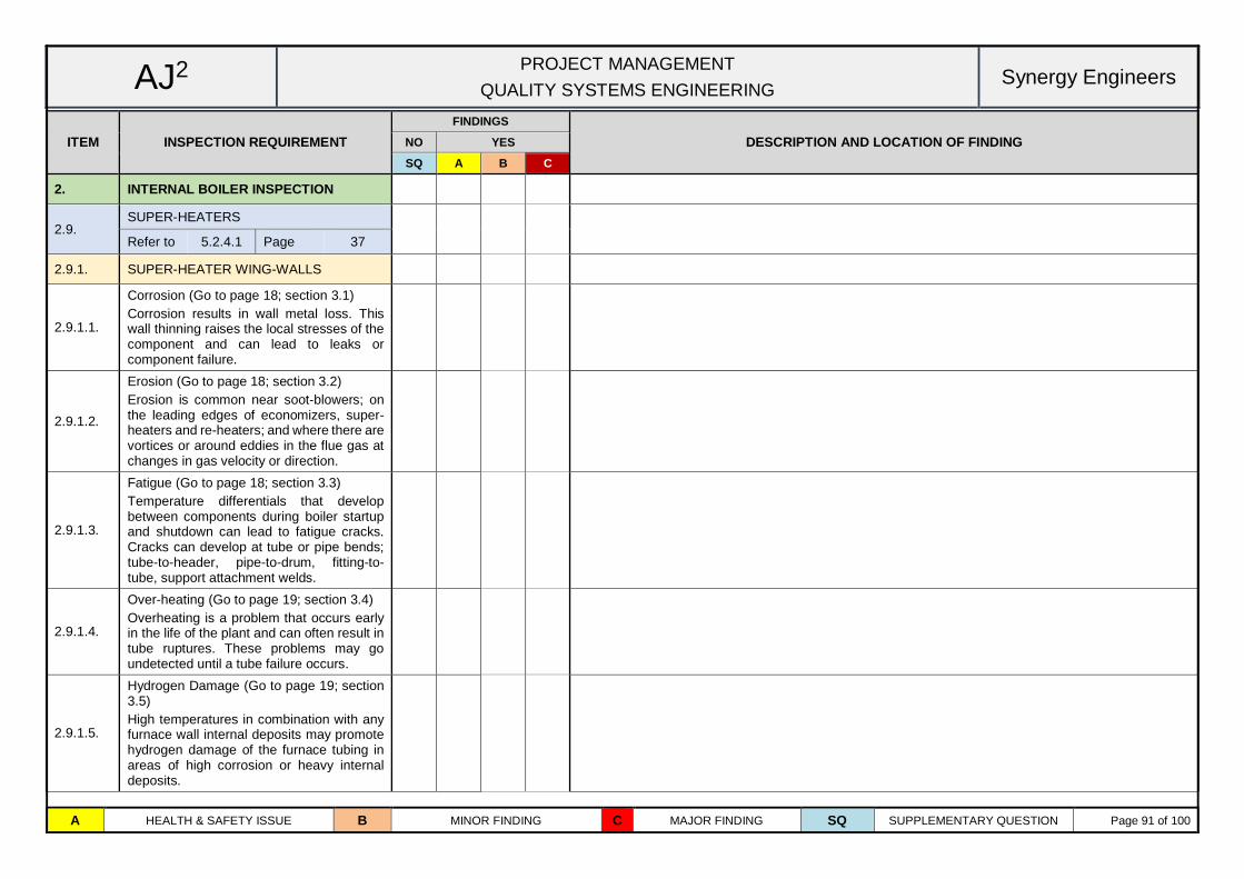
AJ2
PROJECT MANAGEMENT
QUALITY SYSTEMS ENGINEERING Synergy Engineers
A HEALTH & SAFETY ISSUE B MINOR FINDING C MAJOR FINDING SQ SUPPLEMENTARY QUESTION Page 91 of 100
ITEM INSPECTION REQUIREMENT
FINDINGS
DESCRIPTION AND LOCATION OF FINDING NO YES
SQ A B C
2. INTERNAL BOILER INSPECTION
2.9. SUPER-HEATERS
Refer to 5.2.4.1 Page 37
2.9.1. SUPER-HEATER WING-WALLS
2.9.1.1.
Corrosion (Go to page 18; section 3.1)
Corrosion results in wall metal loss. This wall thinning raises the local stresses of the component and can lead to leaks or component failure.
2.9.1.2.
Erosion (Go to page 18; section 3.2)
Erosion is common near soot-blowers; on the leading edges of economizers, super-heaters and re-heaters; and where there are vortices or around eddies in the flue gas at changes in gas velocity or direction.
2.9.1.3.
Fatigue (Go to page 18; section 3.3)
Temperature differentials that develop between components during boiler startup and shutdown can lead to fatigue cracks. Cracks can develop at tube or pipe bends; tube-to-header, pipe-to-drum, fitting-to-tube, support attachment welds.
2.9.1.4.
Over-heating (Go to page 19; section 3.4)
Overheating is a problem that occurs early in the life of the plant and can often result in tube ruptures. These problems may go undetected until a tube failure occurs.
2.9.1.5.
Hydrogen Damage (Go to page 19; section 3.5)
High temperatures in combination with any furnace wall internal deposits may promote hydrogen damage of the furnace tubing in areas of high corrosion or heavy internal deposits.

AJ2
PROJECT MANAGEMENT
QUALITY SYSTEMS ENGINEERING Synergy Engineers
A HEALTH & SAFETY ISSUE B MINOR FINDING C MAJOR FINDING SQ SUPPLEMENTARY QUESTION Page 92 of 100
ITEM INSPECTION REQUIREMENT
FINDINGS
DESCRIPTION AND LOCATION OF FINDING NO YES
SQ A B C
2. INTERNAL BOILER INSPECTION
2.9.2. SECONDARY SUPER-HEATERS
2.9.2.1.
Corrosion (Go to page 18; section 3.1)
Corrosion results in wall metal loss. This wall thinning raises the local stresses of the component and can lead to leaks or component failure.
2.9.2.2.
Erosion (Go to page 18; section 3.2)
Erosion is common near soot-blowers; on the leading edges of economizers, super-heaters and re-heaters; and where there are vortices or around eddies in the flue gas at changes in gas velocity or direction.
2.9.2.3.
Fatigue (Go to page 18; section 3.3)
Temperature differentials that develop between components during boiler startup and shutdown can lead to fatigue cracks. Cracks can develop at tube or pipe bends; tube-to-header, pipe-to-drum, fitting-to-tube, support attachment welds.
2.9.2.4.
Over-heating (Go to page 19; section 3.5)
Overheating is a problem that occurs early in the life of the plant and can often result in tube ruptures. These problems may go undetected until a tube failure occurs.
2.9.2.5.
Hydrogen Damage (Go to page 19; section 3.5)
High temperatures in combination with any furnace wall internal deposits may promote hydrogen damage of the furnace tubing in areas of high corrosion or heavy internal deposits.

AJ2
PROJECT MANAGEMENT
QUALITY SYSTEMS ENGINEERING Synergy Engineers
A HEALTH & SAFETY ISSUE B MINOR FINDING C MAJOR FINDING SQ SUPPLEMENTARY QUESTION Page 93 of 100
ITEM INSPECTION REQUIREMENT
FINDINGS
DESCRIPTION AND LOCATION OF FINDING NO YES
SQ A B C
2. INTERNAL BOILER INSPECTION
2.10. ATTEMPERATORS
Refer to 5.2.7 Page 41
2.10.1.1.
Corrosion (Go to page 18; section 3.1)
Corrosion results in wall metal loss. This wall thinning raises the local stresses of the component and can lead to leaks or component failure.
2.10.1.2.
Erosion (Go to page 18; section 3.2)
Erosion is common near soot-blowers; on the leading edges of economizers, super-heaters and re-heaters; and where there are vortices or around eddies in the flue gas at changes in gas velocity or direction.
2.10.1.3.
Fatigue (Go to page 18; section 3.3)
Temperature differentials that develop between components during boiler startup and shutdown can lead to fatigue cracks. Cracks can develop at tube or pipe bends; tube-to-header, pipe-to-drum, fitting-to-tube, support attachment welds.
2.10.1.4.
Over-heating (Go to page 19; section 3.4)
Overheating is a problem that occurs early in the life of the plant and can often result in tube ruptures. These problems may go undetected until a tube failure occurs.
2.10.1.5.
Hydrogen Damage (Go to page 19; section 3.5)
High temperatures in combination with any furnace wall internal deposits may promote hydrogen damage of the furnace tubing in areas of high corrosion or heavy internal deposits.

AJ2
PROJECT MANAGEMENT
QUALITY SYSTEMS ENGINEERING Synergy Engineers
A HEALTH & SAFETY ISSUE B MINOR FINDING C MAJOR FINDING SQ SUPPLEMENTARY QUESTION Page 94 of 100
ITEM INSPECTION REQUIREMENT
FINDINGS
DESCRIPTION AND LOCATION OF FINDING NO YES
SQ A B C
2. INTERNAL BOILER INSPECTION
2.11. RE-HEATERS
Refer to 5.2.4.1 Page 37
2.11.1. COLD RE-HEATER
2.11.1.1.
Corrosion (Go to page 18; section 3.1)
Corrosion results in wall metal loss. This wall thinning raises the local stresses of the component and can lead to leaks or component failure.
2.11.1.2.
Erosion (Go to page 18; section 3.2)
Erosion is common near soot-blowers; on the leading edges of economizers, super-heaters and re-heaters; and where there are vortices or around eddies in the flue gas at changes in gas velocity or direction.
2.11.1.3.
Fatigue (Go to page 18; section 3.3)
Temperature differentials that develop between components during boiler startup and shutdown can lead to fatigue cracks. Cracks can develop at tube or pipe bends; tube-to-header, pipe-to-drum, fitting-to-tube, support attachment welds.
2.11.1.4.
Over-heating (Go to page 19; section 3.4)
Overheating is a problem that occurs early in the life of the plant and can often result in tube ruptures. These problems may go undetected until a tube failure occurs.
2.11.1.5.
Hydrogen Damage (Go to page 19; section 3.5)
High temperatures in combination with any furnace wall internal deposits may promote hydrogen damage of the furnace tubing in areas of high corrosion or heavy internal deposits.

AJ2
PROJECT MANAGEMENT
QUALITY SYSTEMS ENGINEERING Synergy Engineers
A HEALTH & SAFETY ISSUE B MINOR FINDING C MAJOR FINDING SQ SUPPLEMENTARY QUESTION Page 95 of 100
ITEM INSPECTION REQUIREMENT
FINDINGS
DESCRIPTION AND LOCATION OF FINDING NO YES
SQ A B C
2. INTERNAL BOILER INSPECTION
2.11.2. HOT RE-HEATER
2.11.2.1.
Corrosion (Go to page 18; section 3.1)
Corrosion results in wall metal loss. This wall thinning raises the local stresses of the component and can lead to leaks or component failure.
2.11.2.2.
Erosion (Go to page 18; section 3.2)
Erosion is common near soot-blowers; on the leading edges of economizers, super-heaters and re-heaters; and where there are vortices or around eddies in the flue gas at changes in gas velocity or direction.
2.11.2.3.
Fatigue (Go to page 18; section 3.3)
Temperature differentials that develop between components during boiler startup and shutdown can lead to fatigue cracks. Cracks can develop at tube or pipe bends; tube-to-header, pipe-to-drum, fitting-to-tube, support attachment welds.
2.11.2.4.
Over-heating (Go to page 19; section 3.4)
Overheating is a problem that occurs early in the life of the plant and can often result in tube ruptures. These problems may go undetected until a tube failure occurs.
2.11.2.5.
Hydrogen Damage (Go to page 19; section 3.5)
High temperatures in combination with any furnace wall internal deposits may promote hydrogen damage of the furnace tubing in areas of high corrosion or heavy internal deposits.

AJ2
PROJECT MANAGEMENT
QUALITY SYSTEMS ENGINEERING Synergy Engineers
A HEALTH & SAFETY ISSUE B MINOR FINDING C MAJOR FINDING SQ SUPPLEMENTARY QUESTION Page 96 of 100
ITEM INSPECTION REQUIREMENT
FINDINGS
DESCRIPTION AND LOCATION OF FINDING NO YES
SQ A B C
2. INTERNAL BOILER INSPECTION
2.12. U-BEAMS
Refer to 5.2.4.2 Page 38
2.12.1. IN-FURNACE U-BEAMS
2.12.1.1.
Corrosion (Go to page 18; section 3.1)
Corrosion results in wall metal loss. This wall thinning raises the local stresses of the component and can lead to leaks or component failure.
2.12.1.2.
Erosion (Go to page 18; section 3.2)
Erosion is common near soot-blowers; on the leading edges of economizers, super-heaters and re-heaters; and where there are vortices or around eddies in the flue gas at changes in gas velocity or direction.
2.12.1.3.
Fatigue (Go to page 18; section 3.3)
Temperature differentials that develop between components during boiler startup and shutdown can lead to fatigue cracks. Cracks can develop at tube or pipe bends; tube-to-header, pipe-to-drum, fitting-to-tube, support attachment welds.
2.12.1.4.
Over-heating (Go to page 19; section 3.4)
Overheating is a problem that occurs early in the life of the plant and can often result in tube ruptures. These problems may go undetected until a tube failure occurs.
2.12.1.5.
Hydrogen Damage (Go to page 19; section 3.5)
High temperatures in combination with any furnace wall internal deposits may promote hydrogen damage of the furnace tubing in areas of high corrosion or heavy internal deposits.

AJ2
PROJECT MANAGEMENT
QUALITY SYSTEMS ENGINEERING Synergy Engineers
A HEALTH & SAFETY ISSUE B MINOR FINDING C MAJOR FINDING SQ SUPPLEMENTARY QUESTION Page 97 of 100
ITEM INSPECTION REQUIREMENT
FINDINGS
DESCRIPTION AND LOCATION OF FINDING NO YES
SQ A B C
2. INTERNAL BOILER INSPECTION
2.12.2. U-BEAMS
2.12.2.1.
Corrosion (Go to page 18; section 3.1)
Corrosion results in wall metal loss. This wall thinning raises the local stresses of the component and can lead to leaks or component failure.
2.12.2.2.
Erosion (Go to page 18; section 3.2)
Erosion is common near soot-blowers; on the leading edges of economizers, super-heaters and re-heaters; and where there are vortices or around eddies in the flue gas at changes in gas velocity or direction.
2.12.2.3.
Fatigue (Go to page 18; section 3.3)
Temperature differentials that develop between components during boiler startup and shutdown can lead to fatigue cracks. Cracks can develop at tube or pipe bends; tube-to-header, pipe-to-drum, fitting-to-tube, support attachment welds.
2.12.2.4.
Over-heating (Go to page 19; section 3.4)
Overheating is a problem that occurs early in the life of the plant and can often result in tube ruptures. These problems may go undetected until a tube failure occurs.
2.12.2.5.
Hydrogen damage (Go to page 19; section 3.5)
High temperatures in combination with any furnace wall internal deposits may promote hydrogen damage of the furnace tubing in areas of high corrosion or heavy internal deposits.

AJ2
PROJECT MANAGEMENT
QUALITY SYSTEMS ENGINEERING Synergy Engineers
A HEALTH & SAFETY ISSUE B MINOR FINDING C MAJOR FINDING SQ SUPPLEMENTARY QUESTION Page 98 of 100
ITEM INSPECTION REQUIREMENT
FINDINGS
DESCRIPTION AND LOCATION OF FINDING NO YES
SQ A B C
2. INTERNAL BOILER INSPECTION
2.13. HIGH TEMPERATURE PIPING
Refer to 5.2.8.2 Page 43
2.13.1.1.
Corrosion (Go to page 18; section 3.1)
Corrosion results in wall metal loss. This wall thinning raises the local stresses of the component and can lead to leaks or component failure.
2.13.1.2.
Erosion (Go to page 18; section 3.2)
Erosion is common near soot-blowers; on the leading edges of economizers, super-heaters and re-heaters; and where there are vortices or around eddies in the flue gas at changes in gas velocity or direction.
2.13.1.3.
Fatigue (Go to page 18; section 3.3)
Temperature differentials that develop between components during boiler startup and shutdown can lead to fatigue cracks. Cracks can develop at tube or pipe bends; tube-to-header, pipe-to-drum, fitting-to-tube, support attachment welds.
2.13.1.4.
Over-heating (Go to page 19; section 3.4)
Overheating is a problem that occurs early in the life of the plant and can often result in tube ruptures. These problems may go undetected until a tube failure occurs.
2.13.1.5.
Hydrogen Damage (Go to page 19; section 3.5)
High temperatures in combination with any furnace wall internal deposits may promote hydrogen damage of the furnace tubing in areas of high corrosion or heavy internal deposits.
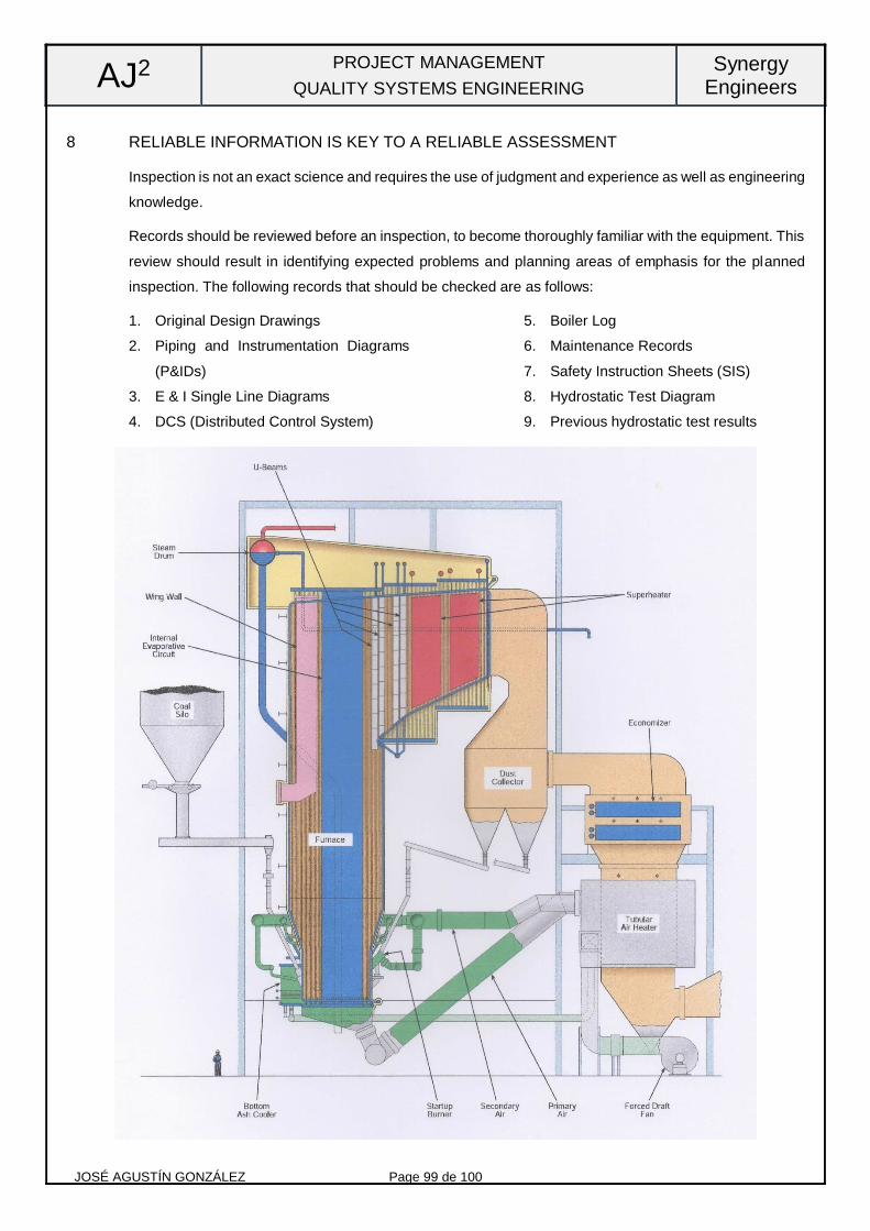
AJ2
PROJECT MANAGEMENT
QUALITY SYSTEMS ENGINEERING
Synergy Engineers
JOSÉ AGUSTÍN GONZÁLEZ Page 99 de 100
8 RELIABLE INFORMATION IS KEY TO A RELIABLE ASSESSMENT
Inspection is not an exact science and requires the use of judgment and experience as well as engineering
knowledge.
Records should be reviewed before an inspection, to become thoroughly familiar with the equipment. This
review should result in identifying expected problems and planning areas of emphasis for the planned
inspection. The following records that should be checked are as follows:
1. Original Design Drawings
2. Piping and Instrumentation Diagrams
(P&IDs)
3. E & I Single Line Diagrams
4. DCS (Distributed Control System)
5. Boiler Log
6. Maintenance Records
7. Safety Instruction Sheets (SIS)
8. Hydrostatic Test Diagram
9. Previous hydrostatic test results

AJ2
PROJECT MANAGEMENT
QUALITY SYSTEMS ENGINEERING
Synergy Engineers
JOSÉ AGUSTÍN GONZÁLEZ Page 100 de 100
9 CFB Boilers – Reheat and Non-reheat
Figure 30 – CFB Boilers Reheat and Non-reheat