Embed Size (px)
Citation preview
Previous Issue: 21 March 2010 Next Planned Update: 11 October 2015
Revised paragraphs are indicated in the right margin Page 1 of 1
Primary contact: Shiha, Saad Mohammed on 966-3-8760163
Copyright©Saudi Aramco 2010. All rights reserved.
Engineering Standard
SAES-L-108 11 October 2010
Se l e c t i o n o f Va l v e s
Document Responsibility: Valves Standards Committee
Saudi Aramco DeskTop Standards
Table of Contents
1 Scope............................................................. 2
2 Conflicts and Deviations................................. 2
3 References..................................................... 2
4 General........................................................... 4
5 General Design Limitations............................ 6
6 Specific Valve Type Limitations...................... 8
7 Specific Service Limitations.......................... 10
8 Materials Limitations..................................... 12 Materials Appendix............................................. 14
Document Responsibility: Valves Standards Committee SAES-L-108
Issue Date: 11 October 2010
Next Planned Update: 11 October 2015 S e l e c t i o n o f V a l v e s
Page 2 of 2
1 Scope
1.1 This Standard covers limitations on the selection of all valves normally
classified under Saudi Aramco Materials System (SAMS) Class 04. This will
normally include ball, butterfly, check, choke, diaphragm, gate, globe, needle,
and plug valves used for on-off, for manual control service or for prevention of
reverse flow, as appropriate.
1.2 Specifically excluded from the scope are:
a) Control, safety-relief, relief, surge relief, solenoid, pilot and other valves
classified under SAMS Class 34.
b) Applications involving flues and chimneys, air conditioning and
ventilation ducts.
c) Drilling and wellhead valves classified under SAMS Class 45.
1.3 Where applicable, this Standard supplements the requirements of ASME B31,
Code for Pressure Piping.
2 Conflicts and Deviations
2.1 Any conflicts between this standard and other applicable Saudi Aramco
Engineering Standards (SAESs), Materials System Specifications (SAMSSs),
Standard Drawings (SASDs), or industry standards, codes, and forms shall be
resolved in writing by the Company or Buyer Representative through the
Manager, Consulting Services Department of Saudi Aramco, Dhahran.
2.2 Direct all requests to deviate from this standard in writing to the Company or
Buyer Representative, who shall follow internal company procedure SAEP-302
and forward such requests to the Manager, Consulting Services Department of
Saudi Aramco, Dhahran.
3 References
The selection of material and equipment, and the design, construction, maintenance, and
repair of equipment and facilities covered by this standard shall comply with the latest
edition of the references below, unless otherwise noted.
3.1 Saudi Aramco References
Saudi Aramco Engineering Procedure
SAEP-302 Instructions for Obtaining a Waiver of a
Mandatory Saudi Aramco Engineering
Requirement

Document Responsibility: Valves Standards Committee SAES-L-108
Issue Date: 11 October 2010
Next Planned Update: 11 October 2015 S e l e c t i o n o f V a l v e s
Page 3 of 3
Saudi Aramco Engineering Standards
SAES-B-017 Fire Water System Design
SAES-L-102 Regulated Vendor List for Valves
SAES-L-110 Limitations on Pipe Joints and Components
SAES-L-133 Corrosion Protection Requirements for
Pipelines/Piping
SAES-L-136 Pipe Selection and Restriction
Saudi Aramco Materials System Specifications
04-SAMSS-001 Gate Valves
04-SAMSS-002 Globe Valves
04-SAMSS-003 Additional Requirements for Low Temperature
Valves
04-SAMSS-005 Swing Check Valves
04-SAMSS-035 General Requirements for Valves
04-SAMSS-041 Expanding Plug Valve
04-SAMSS-042 4-Way Diverter Valves
04-SAMSS-048 Valve Inspection and Testing Requirements
04-SAMSS-049 Inspection & Testing Requirements for
API SPEC 6A 10,000 psi Valves
04-SAMSS-050 Thru-conduit Gate Valves
04-SAMSS-051 API SPED 6D Ball Valves
04-SAMSS-052 API SPEC 6A Ball Valves
09-SAMSS-080 Shop-Applied Baked Internal Coatings
09-SAMSS-091 Qualification Requirements for Shop-Applied
Internal FBE Coatings
Saudi Aramco Form and Data Sheet
6233-1-ENG Valve Data Sheet
3.2 Industry Codes and Standards
American National Standards Institute/Fluid Controls Institute
ANSI/FCI 70.2 Control Valve Seat Leakage

Document Responsibility: Valves Standards Committee SAES-L-108
Issue Date: 11 October 2010
Next Planned Update: 11 October 2015 S e l e c t i o n o f V a l v e s
Page 4 of 4
American Petroleum Institute
API SPEC 6A Specification for Wellhead and Christmas Tree
Equipment
API SPEC 6D Specification for Pipeline Valves
API SPEC 6FA Specification for Fire Test for Valves
API STD 598 Valve Inspection and Testing
API STD 602 Compact Steel Gate Valves - Flanged, Threaded,
Welding, and Extended-Body Ends
API STD 607 Fire Test for Soft Seated Quarter-Turn Valves
API STD 609 Butterfly Valves, Lug-Type and Wafer-Type
American Society of Mechanical Engineers
ASME B16.5 Steel Pipe Flanges and Flanged Fittings
ASME B16.34 Valves - Flanged, Threaded, and Welding End
ASME B31 Code for Pressure Piping
British Standards Institution
BS 6755 Testing of Valves
Manufacturers Standardization Society of the Valve and Fittings Industry, Inc.
MSS SP-45 Bypass and Drain Connection Standard
National Association of Corrosion Engineers/International Standardization
Organization
NACE MR0175/ISO 15156 Petroleum and Natural Gas Industries –
Materials for Use in H2S Containing
Environments in Oil and Gas Production
4 General
4.1 Valves shall be purchased from approved manufacturers listed in SAES-L-102.
Approval of purchase from manufacturers not listed in this document shall be
strictly governed by the provisions provided therein.
4.2 The selection of valves shall normally be limited to the materials, types and
sizes that are listed in SAMS Class 04 unless no suitable valve is listed.
Document Responsibility: Valves Standards Committee SAES-L-108
Issue Date: 11 October 2010
Next Planned Update: 11 October 2015 S e l e c t i o n o f V a l v e s
Page 5 of 5
4.3 Whenever applicable, the relevant Saudi Aramco Materials System
Specifications (SAMSS's) listed in Section 3 of this Standard shall be included
in all requisitions.
4.4 At times it is necessary to purchase a valve that is generally similar to that
covered by an SAMSS but differing from it in some specific design,
construction, materials or performance characteristics. In such cases, the
SAMSS shall be included in the purchase requisition in addition to the required
modifications provided that these modifications are in accordance with all other
Mandatory Saudi Aramco Engineering Requirements.
4.5 All valve requisitions, except those for API SPEC 6A 10000 psi valves 2-1/16
inch and larger, shall reference 04-SAMSS-035, General Requirements for
Valves, and 04-SAMSS-048, Valve Inspection & Testing Requirements.
4.6 Form 6233-1-ENG, Valve Data Sheet, shall be filled out and attached to every
non-SAMS class 04 valve purchase requisition.
4.7 Field Tests
4.7.1 Testing location shall be specified by proponent.
4.7.2 If requested by the proponent, all new valves designated for isolation
service (as specified by the Proponent) shall be subjected to a high
pressure hydrostatic seat test prior to installation in the line.
4.7.3 A low pressure pneumatic seat test at 35 kPa (5 psig) shall be
substituted for the high pressure hydrostatic seat test for flare system
valves.
4.7.4 Buttweld and socketweld end valves in nominal pipe size (NPS) 2
inches and smaller are exempt from the above field testing
requirements.
4.7.5 Test procedures, pressures, durations, and leakage acceptance criteria
shall be equal to those that the valves were originally purchased to. All
resilient (soft) seated isolation valves shall have zero leakage.
4.8 The use of ANSI FCI 70.2 to specify seat leakage criteria is not permitted
without the specific approval of the Chairman of the Valves Standards
Committee.
4.9 Trim material includes the stem, the body and closure seating surfaces,
bushings, pins, springs, guides, and any other small parts in contact with the
service fluid.

Document Responsibility: Valves Standards Committee SAES-L-108
Issue Date: 11 October 2010
Next Planned Update: 11 October 2015 S e l e c t i o n o f V a l v e s
Page 6 of 6
5 General Design Limitations
5.1 Bonnet/Cover
5.1.1 Pressure seal bonnet valves shall be used only in steam or other clean
non-corrosive services. They are permitted in other services only if the
body has been inlayed in the bonnet sealing area with an 18-8 material
or higher alloy suitable for the service.
5.1.2 Bonnets retained by split rings and sealed by means of an O-ring or a
seal-welded membrane shall only be used after approval by the
Chairman of the Valves Standards Committee.
5.1.3 The use of welded bonnet valves in hydrocarbon services shall be
limited to NPS 4 inch and smaller provided it is approved by the
Manager of the responsible operating department.
5.1.4 Screwed bonnet and screwed body valves shall not be used in any
hydrocarbon or hazardous material services unless the bonnets and
body end connections are tack welded to the body or provided with
locking pin.
5.1.5 Straight-thru union body check valves shall be used only in portions of
piping systems where pipe unions are permissible.
5.1.6 Union bonnet valves shall not be used in any hydrocarbon or hazardous
material services.
5.2 End Connections
5.2.1 The requirements of SAES-L-110 are applicable to all valves.
5.2.2 Integral flanged valve bodies with tapped bolt holes shall not be used
except with specific approval of the Proponent and the Chairman of the
Valves Standards Committee. These requirements do not apply to lug
type valves.
5.2.3 If requested by the proponent, critical valves, welding end valves, and
others that cannot be removed from the line without serious difficulty
(e.g., in restrained pipelines), NPS 8 inch and larger, shall be of a type
that is repairable in the line (top-entry) provided it is specifically
approved by the Chairman of the Valves Standards Committee.
5.3 Ratings
5.3.1 Valves utilizing soft seats do not necessarily follow ASME B16.5 or

Document Responsibility: Valves Standards Committee SAES-L-108
Issue Date: 11 October 2010
Next Planned Update: 11 October 2015 S e l e c t i o n o f V a l v e s
Page 7 of 7
other industry standard pressure/temperature relationships at
temperatures above 38°C. The specific Vendor's literature shall be
consulted when the pressure-temperature ratings for higher
temperatures have not been specified by the relevant SAMSS or the
Purchase Order.
5.3.2 In hydrocarbon services, the minimum body rating of threaded and
socketweld end NPS 2 inch and smaller valves shall be equivalent to
API STD 602 Class 800.
5.4 Sizes
Valves shall be subject to the same size limitations specified for pipe in
SAES-L-136.
5.5 Stem Packing
Isolation valves NPS 3 inch and larger in hydrocarbon services shall not be
provided with pure polymer/elastomer stem packing or stem seals unless the
valves have been qualified as fire-safe, except as permitted by an approved
SAMSS.
5.6 Actuators
5.6.1 The need for power actuation of all valves NPS 12 inch and larger in
all pressure classes shall be reviewed with the responsible operating
organization.
5.6.2 Chainwheel operation shall not be provided for emergency isolation
valves or valves having a threaded body connection.
5.7 Installation
5.7.1 Gate valves with back-seats shall not be installed with their stems
below the horizontal except in the following cases: (a) clean services,
(b) when they function as isolation valves in pressure relief and flare
system piping, and (c) when in utility or other similar non-critical
services (firewater is considered to be critical service).
Note: Critical / non-critical valves shall be specified by proponent and specifically approved by the Chairman of the Valves Standards Committee.
5.7.2 Seal welding
5.7.2.1 All threaded connections on valve bodies and associated
piping shall be seal welded.

Document Responsibility: Valves Standards Committee SAES-L-108
Issue Date: 11 October 2010
Next Planned Update: 11 October 2015 S e l e c t i o n o f V a l v e s
Page 8 of 8
Exceptions:
Exceptions are those connections that are frequently disassembled (such as vent and drain plugs) and those that are adjacent to elements that contain small moving parts (such as injection fittings and body relief valves).
5.7.2.2 Seal welding shall follow the general requirements of
SAES-L-110.
5.8 Coating
The body of steel gate valve shall not be internally coated unless the wedge is
rubber-lined.
6 Specific Valve Type Limitations
6.1 Ball Valves
Lever operated ball valves shall be equipped with a handwheel or self-locking
handle to prevent accidental operation.
6.2 Butterfly Valves
6.2.1 Concentric butterfly valves, such as the API STD 609 Category A type
(typically with internal rubber linings), are permitted only in non-
hydrocarbon applications.
6.2.2 The use of high performance butterfly valves in hydrocarbon service
shall be limited to a maximum rating of Class 900. Minimum
requirements in hydrocarbon service are as follows:
a) Valves shall be designed in accordance with API STD 609
Category B valves with offset-seat type construction.
b) Valves shall be qualified fire-safe to either API SPEC 6FA,
API STD 607, or BS 6755 Part 2, except in applications where
other components of the system are not designed to be firesafe
such as Single-Point-Mooring (SPM) systems.
c) The body shall be of the lug-type design with tapped bolt holes,
unless the (double) flanged type has been specified. Use of the
wafer-type body is not permitted.
d) Valves shall be full-rated. In systems where the normal operating
pressure is 103 kPa (15 psig) or less, the valve may be specified

Document Responsibility: Valves Standards Committee SAES-L-108
Issue Date: 11 October 2010
Next Planned Update: 11 October 2015 S e l e c t i o n o f V a l v e s
Page 9 of 9
with half-rated trim (approximately 50% of the full-rated
pressure).
e) Valves shall be bi-directional, although they may have a
"preferred" direction. Valves shall be installed in the "preferred"
direction indicated on the valve.
6.3 Check Valves
6.3.1 Dual and single plate wafer check and swing check valves shall not be
used in reciprocating pump and compressor suction and discharge
services or similar pulsating services.
6.3.2 A non-slam internal-spring-assisted type check valve shall be installed
at the discharge of pumps and compressors. Other check valve types
shall be specifically approved by the Chairman of the Valves Standards
Committee.
6.3.3 If requested by the proponent, for parallel pump systems with
individual pump discharge piping of NPS 20 inch and larger, a
hydraulic analysis shall be conducted to verify that the selected check
valves have the correct dynamic response to prevent slamming and
limit pressure surge to an acceptable level. The analysis shall include
consideration of the "worst case" operating mode scenario.
6.3.4 For all sizes NPS 4 inch and above, a turbulence-free minimum
distance of 5 pipe diameters upstream and 2 pipe diameters
downstream of every check valve shall be maintained. No pipe fittings
such as elbows, reducers, tees, etc., or flow restricting devices such as
orifices, control valves, etc., shall be installed in these zones unless
specifically approved by the Chairman of the Valves Standards
Committee. Valves in intermittent service and valves in skid-mounted
systems are exempt from these requirements.
6.3.5 Check valves in sizes NPS 3 inch and above shall not be installed in
vertical lines, unless specifically approved by the Chairman of the
Valve Standards Committee. Valves in skid-mounted systems are
exempt from this requirement.
6.3.6 Check valves in hydrocarbon service up to Class 600 shall either have
a lug-type body with tapped bolt holes or a flanged body. In higher
ratings, a flanged body is mandatory. Wafer-type bodies are not
permitted in any hydrocarbon service.
6.3.7 Spring-assisted non-slam piston check valves (also referred to as
nozzle check valves) shall be long-pattern with face-to-face
Document Responsibility: Valves Standards Committee SAES-L-108
Issue Date: 11 October 2010
Next Planned Update: 11 October 2015 S e l e c t i o n o f V a l v e s
Page 10 of 10
dimensions in accordance with API SPEC 6D. Short-pattern valves
shall not be used without the review and approval of the Chairman of
the Valves Standards Committee.
6.4 Plug Valves (Hydrocarbon service only)
Flanged plug valves in hydrocarbon service shall be of the inverted lubricated
pressure balanced design, except that Class 150 valves NPS 6 inch and smaller
may have a standard plug with springs for balancing the plug.
7 Specific Service Limitations
7.1 Low Temperature Services
7.1.1 Valves in services between -45°C and -18°C shall meet the
requirements of 04-SAMSS-003. If the service is also sour,
compliance with NACE MR0175/ISO 15156 shall be specifically
stated in the purchase requisition.
7.1.2 All valves in services below -45°C shall be full austenitic stainless steel
and shall meet the requirements of 04-SAMSS-003, paragraph 6.3.
7.1.3 All valves in service below -100°C shall have an extended bonnet.
7.1.4 For LPG or high pressure gases which autorefrigerate, an upstream
gate valve shall be installed in addition to the throttling valve in any
line that discharges to the atmosphere or to a low pressure system.
7.2 Underwater Valves
Isolation valves shall be ball type per 04-SAMSS-051 with a minimum rating of
Class 300. The flange face shall be the ring joint type.
7.3 Pressure Relief Valve Piping
Isolation valves in stand-alone pressure relief valve inlet and discharge piping
shall be gate, ball, high performance butterfly (flanged) or plug valves that can
be car-sealed open. A gate valve in this service shall be installed with the stem
in or below the horizontal position. For clean gas service, the valves shall be
soft seated with double block and bleed capability if temperature permits.
7.4 Flare Systems
7.4.1 Isolation valves in flare system piping shall be gate, ball, high
performance butterfly or plug valves.

Document Responsibility: Valves Standards Committee SAES-L-108
Issue Date: 11 October 2010
Next Planned Update: 11 October 2015 S e l e c t i o n o f V a l v e s
Page 11 of 11
7.4.2 A gate valve in this service shall be installed with the stem in or below
the horizontal position.
7.5 Emergency Isolation Valves
Emergency isolation valves (EIVs) shall be gate, ball, high performance
butterfly (flanged) or plug valves. Soft seated valves shall be fire safe in
accordance with API STD 607, API SPEC 6FA, or BS 6755 Part 2. Metal
seated valves shall meet the same requirement if they do not have graphite seals
or their standard specified leakage rate exceeds that of API STD 598.
7.6 Firewater Systems
Buried sectionalizing valves in firewater systems shall meet the requirements of
SAES-B-017.
7.7 Drains and Vents
Atmospheric drain and vent valves shall be provided with a plug or blind on the
discharge side.
7.8 Storage Tanks and Vessels
Flangeless valves shall not be used as the first block valve against storage tanks
or vessels containing hazardous materials unless specifically approved by the
Chairman of the Valves Standards Committee.
7.9 API SPEC 6A 10,000 psi services
7.9.1 Valves shall only be purchased from manufacturers approved in
accordance with SAES-L-102.
7.9.2 Valves shall be tested and inspected in accordance with 04-SAMSS-049.
7.10 Scraper Trap Valves
7.10.1 Scraper trap mainline isolation valves shall be full bore thru-conduit
gate or ball valves.
7.10.2 Drain valves shall be inverted pressure balanced lubricated plug valves
with Stellite hardfacing on the plug and body seating surfaces.
7.10.3 Kicker valves and vent valves shall be inverted pressure balanced
lubricated plug valves.
7.10.4 The scraper trap isolation valve and the kicker valve shall have a
minimum trim metallurgy of SS F 51 regardless of service. In
Document Responsibility: Valves Standards Committee SAES-L-108
Issue Date: 11 October 2010
Next Planned Update: 11 October 2015 S e l e c t i o n o f V a l v e s
Page 12 of 12
addition, the valve seat pockets (applicable to spring loaded seats only)
shall be specified to have an Inconel 625 weld overlay. The
requirements of this paragraph override the materials requirements
listed in the Appendix, unless those are more stringent.
7.11 Instrumentation root isolation valves
7.11.1 Instrumentation root isolation valves shall be API STD 602 gate
valves. Approval of equivalents shall be referred to the Chairman of
the Valves Standards Committee.
7.11.2 Modular valve assemblies consisting of a root isolation valve together
with bleed/vent and other types of valves and instruments are permitted
subject to specific review and approval by the Chairman of the Valves
Standards Committee on a case-by-case basis.
7.12 Steam service
Isolation valves, NPS 2 inch and larger, in Class 600 and higher rated systems
shall be parallel slide gate valves equipped with a cavity pressure relief system.
Other gate type shall be specifically approved by the Chairman of the Valves
Standards Committee.
7.13 Blowdown Valves
Blowdown valves in gas pipelines shall be plug valves.
7.14 Bypass/equalization valves
Mainline bypass/equalization valves in gas service shall be inverted pressure
balanced lubricated plug valves.
8 Materials Limitations
8.1 Valves with bodies of cast iron, ductile iron, or low melting point alloys (such as
brass or bronze) shall not be used in hydrocarbon services.
8.2 Valves with steel bodies shall be used in the following cases:
a) The first valve on all tanks and other vessels if failure could create a
personnel or fire hazard or result in a large monetary loss.
b) In hazardous areas where it is essential that the valve not fail in a fire.
8.3 Minimum material requirements are specified in the attached Materials
Appendix, except as modified above. Refer to paragraph 4.3 for cases where the
required materials differ from those in the SAMSS.

Document Responsibility: Valves Standards Committee SAES-L-108
Issue Date: 11 October 2010
Next Planned Update: 11 October 2015 S e l e c t i o n o f V a l v e s
Page 13 of 13
8.4 When austenitic stainless steels are to be seal-welded, welded or overlaid, low
carbon grades shall be specified.
Revision Summary 11 October 2010 Revised the "Next Planned Update". Reaffirmed the contents of the document, and reissued
with editorial changes to reflect the changes in committee members list.

Document Responsibility: Valves Standards Committee SAES-L-108
Issue Date: 11 October 2010
Next Planned Update: 11 October 2015 S e l e c t i o n o f V a l v e s
Page 14 of 14
Materials Appendix
Table I – Service and Application Requirements Valve Body and Trim Materials
Conditions Valve Materials Environment Conc.(%) Temp.(C) Body Trim Remarks Acid, Hydrochloric LT 37 5 - 50 PVC PVC No ferric ions or other B-2 B-2 oxidants for B-2 Acid, Hydrofluoric 1 - 70 5 - 50 M400 C-276 No glass or glass reinforced non-oxidizing GT 65 5 - 40 PTFE PTFE plastics; no titanium, zirconium or tantalum Acid, Hydrofluoric All conc. to 50 20 20 (aerated or oxidizing) Acid, Nitric 1 - 70 5 - 50 304L (6) 304L 304L is preferred to 316L for 70 - 99 30 max. 304L 304L nitric acid Acid, Phosphoric 1 - 85 5 - 50 316 316L Applies to chloride or fluoride G-3(X) G-3(X) free grades of phosphoric acid only Acid, Sulfuric(8) 90 -100+ to 50 316 316L or Sulfurous 1 -103 to 65 20 20 to 60 to 65 CPVC CPVC 1 - 100 100 C-276 C-276 ADIP (Amino- 20 - 30 5 - 150 CS 316 No copper alloys allowed Diisopropanol) Air or Nitrogen gas N/A 0 - 400 CS 410 BR BR Ammonia, 100 0 - 50 CS 410 No copper alloys allowed Anhydrous (10) Carbon Dioxide dry 100 0 - 150 CS 410 wet LT 100 5 - 90 316 316 Chlorine, dry (12) 100 0 - 70 CS M400 M400 M400 wet (13) LT 100 0 - 70 PVC PVC C-276 C-276 For castings, Hastelloy C-4 is preferred to C-276 Chlorine/Water 1 - 5 to 50 PVC PVC 50 - 80 CPVC CPVC to 80 C-276 C-276 For castings, Hastelloy C-4 is preferred to C-276
(Refer to General and Specific Notes at the end of Table 1)

Document Responsibility: Valves Standards Committee SAES-L-108
Issue Date: 11 October 2010
Next Planned Update: 11 October 2015 S e l e c t i o n o f V a l v e s
Page 15 of 15
Table I (Cont'd)
Conditions Valve Materials Environment Conc.(%) Temp.(C) Body Trim Remarks Crude Oil or N/A to 220 CS ENP Up to 10% water cut only Product (15) (10 year projected rate)
TEFZEL or PEEK soft seals and seats shall be specified if valves will be exposed to acidizing conditions
to 280 CS 410 CS 316 CS TC 280 to 340 CrMo5 410 340 to 500 316 316 Diglycolamine to 100 to 65 CS 410 Use 316 bodied valves where (DGA) or CS 316(X) 304 or 316S.S. pipe is Diethanolamine 20 - 70 5 - 190 CS 316 employed or for throttling (DEA) 316(X) 316 applications Flare Lines N/A to 400 CS 410 CS 316 Freon 100 0 to 70 CS 410 -100 to 0 316 316 Hydrocarbon Gas N/A -18 to 220 CS ENP ENP trim not permitted including Khuff - 18 to 280 CS 410 for wet or sour gas Gas (15, 18) CS 316 (Ref: SAES-L-133 CS TC para 3.1,3.2,3.3) Hydrogen (16) 100 0 - 220 CS ENP Same restriction on ENP as CS 410 above 316(X) 316(X) 220 to 325 CrMo22 410 316(X) 316(X) 325 to 400 316 316 Hypochlorite, to 5 5 - 50 PVC PVC Treat same as chlorine/water Sodium or Calcium C-276 C-276 solutions Light Hydrocarbons 100 -18 to 220 CS ENP ENP trim not permitted for (Butane, Ethane, -18 to 400 CS 410 wet or sour gas Hexane, Methane, CS 316 Pentane and CS TC Propane) and -45 to -18 LTS 316 NGL LT -45 304 304 316 316 Lube Oil 100 5 - 120 CS 410 304 304 316 316 (Refer to General and Specific Notes at the end of Table 1)

Document Responsibility: Valves Standards Committee SAES-L-108
Issue Date: 11 October 2010
Next Planned Update: 11 October 2015 S e l e c t i o n o f V a l v e s
Page 16 of 16
Table I (Cont'd)
Conditions Valve Materials Environment Conc.(%) Temp.(C) Body Trim Remarks Naphtha 100 0 - 150 CS 410 CS 316(X) Sewer, Oily Water N/A 5 - 50 DI (7) Br(20) Sewer, N/A 5 - 50 DI (7) Br(20) Storm or Br (20) Br(20) Sanitary PVC PVC Sodium 50 5 - 50 D2 20 Hydroxide 316(X) 316(X) 50 - 80 CS M400 M400(X) M400 (2) 20 5 - 50 CS M400 304L(X) 304L(X) 7 5 - 80 CS 316 CS M400 7 80 - 100 M400 M400 Steam 100 120 - 400 CS 410 Seat rings shall be overlayed 400 - 480 CRMoll 410 with Stellite. For Class 600 systems and higher, all seating areas shall be overlayed Steam 100 5 - 120 CS 410 Condensate CS 410 Sulfur Dioxide 0.5 C-276 C-276 Solution in deaerated sea- (Solution) water, pH 1.5 Sulfur Molten 100 GT 107 CS 316 Keep dry. Moisture causes corrosion Water Non-corrosive N/A 0 - 100 CS 410 Includes deaerated and/or (oxygen free or D1 (7) Br inhibited sea, raw, well water (inhibited) Br Br Zeolite softened, chilled, and CS 316 boiler feed water. pH GT 6, oxygen LT 25 ppb Potable (Sweet) N/A 5 - 50 Br (20) Br (20) PVC PVC CS (26) 316 D1 (7) Br (20) 50 - 72 Br (20) Br (20) CPVC CPVC CS (26) 316 (Refer to General and Specific Notes at the end of Table 1)

Document Responsibility: Valves Standards Committee SAES-L-108
Issue Date: 11 October 2010
Next Planned Update: 11 October 2015 S e l e c t i o n o f V a l v e s
Page 17 of 17
Table I (Cont'd)
Conditions Valve Materials Environment Conc.(%) Temp.(C) Body Trim Remarks Saline N/A 5 - 80 SSS SSS For sour brine, formation and (includes all SSS Ti disposal water, and other untreated sea, Br (20) Br (20) highly corrosive waters such raw, well, and as untreated sea water, aquifier waters) Wasia water, upto NPS (Aerated, corrosive) 4-inch. (21,23) (14, 28, 29) CS SSS For larger sizes, body shall be internally lined or coated. CS (24) Br (20) (22) CS 316 (27) DI Br (20) Br (20) Br (20) For low pressure utility D2 Br (20) service waters (raw water, DI (7) Br (20) well water) which are not as aggressive. Soft or Pure N/A 5 - 500 PVC PVC Includes Zeolite softened, 304 304 distilled or demineralized. 316 316 General Notes:
(A) All valve designs shall incorporate features required to resist galling of mating surfaces by means of necessary hardness differentials, weld overlays, galling resistant material combinations, etc.
(B) Trim material includes the stem, the body and closure seating surfaces, bushings, pins, springs, guides, or any small parts in contact with the service fluid.
(C) The gate, disc, piston, ball, or plug that provide closure are normally made from the "trim" material in smaller valve sizes (less than about 6 inches). The closure may be made from material equivalent to the valve body except that the closure seating surfaces shall be of the material having a corrosion resistance equal to or "better" than the trim.
(D) See Table IV(a), (b) and (c) for material designations.
(E) LT means "Less Than", GT means "Greater Than."
(F) (X) indicates materials for critical applications such as hazardous service, poor accessibility for maintenance, or significant loss of production in the event of failure.
(G) Austenitic ("300 Series") stainless steel components that are to be welded or weld overlaid shall be low carbon (.03% carbon maximum) grades. Low carbon grades may be substituted for regular carbon grades, but not vice versa.
Specific Notes:
(2) Monel K-500 may be substituted for Monel 400 where additional hardness or strength is required.
(6) Do not expose stainless-steel trim to HCl acid-cleaning.
(7) Gray cast iron valve bodies may be substituted for ductile iron. However, ductile iron is preferred.

Document Responsibility: Valves Standards Committee SAES-L-108
Issue Date: 11 October 2010
Next Planned Update: 11 October 2015 S e l e c t i o n o f V a l v e s
Page 18 of 18
Table I (Cont'd)
(8) Sulfuric acid concentrations over 100% ("Oleum") contain free sulfur trioxide.
(10) Inhibited against stress corrosion cracking of steel with minimum 2000 ppm water.
(12) Dry chlorine contains less than 2000 ppm water; do not use with titanium components.
(13) Wet chlorine contains at least 2000 ppm water.
(14) These services are subject to additional considerations such as galvanic compatibility, velocity effects or additional water chemistry factors. For example, high velocities or low pH may dictate against the use of bronze trim or Ductile Iron (DI) bodies. Copper alloy bodied valves shall not be used with carbon steel pipe in corrosive water service without the use of insulating sets.
(15) Materials for valves in wet sour service shall meet the requirements of NACE MR0175/ISO 15156. NACE MR0175/ISO 15156 defines sour service. See also SAES-L-133.
(16) See Nelson Charts for details concerning the influence of temperature and partial pressure of hydrogen on material selection.
(18) Body materials for Khuff Gas valves are per API SPEC 6A. Drain valves and valves at low points where water may collect under stagnant conditions shall have 316 stainless steel "or better" bodies.
(20) Where indicated, the zinc content of wetted copper alloy components shall be 16% or less.
(21) Availability of bronze valves in ratings above Class 150 is limited, and have not yet been tried in Saudi Aramco.
(22) Linings are generally used in butterfly valves, non-lubricated plug valves, and some wedge gate valves. Coatings are used on ball, check, globe and gate valves, and shall be specified in accordance with 09-SAMSS-080 and 09-SAMSS-091 as applicable.
(23) Sour brine services may require specification of NACE MR0175/ISO 15156.
(24) Use ductile iron body, if available, for butterfly valves in non-hydrocarbon services.
(26) For potable water service, carbon steel body valves with SS316 trim are allowed in NPS 4-inch and above only. For critical service, use coated or lined valves.
(27) Type 316 trim is only acceptable when there is a high degree of confidence that occasional oxygen ingress cannot occur due to startup conditions, pump or valve packing leaks, etc. All trim shall be full SS316.
(28) Carbon steel overlaid with Inconel 625 may be substituted for super austenitic or duplex stainless steels (SSS) provided that (a) the entire exposed area is overlaid and (b) the fused material has no more than 30% dilution.
(29) Where seawater is chlorinated, residual chlorine should be limited to 2 ppm or less for SSS alloys rated A in Table IV-B, 1 ppm for those rated B, and 0.5 ppm for those rated C. Where residual chlorine exceeds 2 ppm, the Alloy C family of alloys in Table IV-A should be considered.

Document Responsibility: Valves Standards Committee SAES-L-108
Issue Date: 11 October 2010
Next Planned Update: 11 October 2015 S e l e c t i o n o f V a l v e s
Page 19 of 19
Table II – Alternate Stem and Spring Materials
The stem and spring alloys listed below may be used in valves having the trim materials
specified in Table I. These alloys usually may be fabricated to the required strength
levels more readily than the general trim materials and their corrosion resistance is
approximately equal to or better than that of the corresponding general trim.
Alternate Alternate Specified Trim Stem Materials Spring Materials (2)
Stainless Steels 410 17-4, A286 17-4, X750, 600 6NM 17-4, A286 17-4, X750, 600 304 17-4, A286 17-4, X750, 600 316 N50, 718 718, MP35N, E1g 20 625 MP35N, Elg, 625, C-276 SSS 625 MP35N, Elg, 625, C-276 Low Alloy Steels CrMoll, CrMo22, CrMo5 17-4, 410 17-4, X750 Copper Alloys M400, MK500, SSS, 625, C-276, MP35N, Elg Br Aluminum Bronze, Nickel Aluminum Bronze, Silicon Bronze C69400 Nickel Base Alloys M400 MK500, 718, C-276 (1) MP35N, Elg, C-276, 625, 718 G-3 625, C-276 MP35N, Elg, C-276, 625
Notes:
(1) A specialized application for gaseous chlorine service.
(2) Iron base alloy springs shall not be used in sour service.

Document Responsibility: Valves Standards Committee SAES-L-108
Issue Date: 11 October 2010
Next Planned Update: 11 October 2015 S e l e c t i o n o f V a l v e s
Page 20 of 20
Table III – Service and Application Requirements - Plastic/Elastomeric Components
M A T E R I A L S (2) (See Table IV) (See Notes 7 and 8) Regarding Flurocarbon Materials) Environment (1) O-Rings, Diaphragms & Resilient Seats (8) Plastic Parts (7)
Acid, Hydrochloric EPDM, PTR, IIR, CR PVC, CPVC, PE, PP Acid, Hydrofluoric CSM, PTR PP, PE, PVDC, CPE Acid, Nitric to 100% PTFE/Elastomer PF(3) CPE, PTFE, FEP to 60% Fluorocarbon Elastomer CPVC, CPE Acid, Phosphoric EPDM, IIR, CR, RN, CSM PVC, CPVC, PE, PP, CPE, PVDC Acid, Sulfuric Oleum PTFE/Elastomer, PF Fluorocarbon Plastics only, except PVDF Acid, Sulfuric 90%+ CSM PVDC, CPE LT 60% CR, CSM, IIR, EPDM PVDC, CPE, CPVC Acid, Sulfurous Fluorocarbon elastomers Air Any within dry temperature and pressure limits Ammonia (8) Any except amine cured FKM, TFE/P Any except Nylon Amines (MEA, DEA, DGA, VMQ, EPDM, PTR, CSM (amine FEP, PTFE ADIP) (8) cured FKM, TFE/P not suitable) Carbon Dioxide, Dry Any within dry temperature limits 150°C and pressure limits Carbon Dioxide, Wet Any within temperature/ 90°C pressure limits Chlorine, Dry Fluorocarbon Elastomers FVMQ (4) Fluorocarbon Plastics Chlorine, Wet Fluorocarbon Elastomers FVMQ PVC, CPVC Crude Oil to 50°C Fluorocarbon Elastomers PVC, CPVC, PP, PPS to 200°C Fluorocarbon Elastomers Fluorocarbon Plastics Freon 11 or 12 NBR, CSM, ECO, TFE/E CPVC, Nylon (FKM not suitable)

Document Responsibility: Valves Standards Committee SAES-L-108
Issue Date: 11 October 2010
Next Planned Update: 11 October 2015 S e l e c t i o n o f V a l v e s
Page 21 of 21
Table III (Cont'd)
M A T E R I A L S (2) (See Table IV) (See Notes 7 and 8) Regarding Flurocarbon Materials) Environment (1) O-Rings, Diaphragms & Resilient Seats (8) Plastic Parts (7) Gas [T LT 121°C Fluorocarbon Elastomers (5) PVC, CPVC, PPS (250°F)] Gasoline (9) FKM,PTR,FVMQ PVDF,PVDC,CPE Gasoline, MTBE blend NBR (min. 40% acrylonitrile) Fluorocarbon plastics Hydrogen Sulfide PTR,CSM,EPDM PE, PP, PVC, PVDF Hypochlorite, Ca/Na Butyl, CSM , CR, ECO PVC, CPVC, PCDC Light Hydrocarbons PTR, ECO, FKM, FVMQ Fluorocarbon Plastics, PPS (Butane, Ethane, Methane, Pentane, Propane) Naphtha PTR, ECO, FVMQ PVDC, CPE Sewage, Oily CR, NBR, PTR PVC, CPVC, PVDC Sewage, Sanitary Any Any Sodium Hydroxide Any except FKM and TFE/P Any except PVDC at high conc. Sodium Carbonate (all conc.) Any Polypropylene, RN, PVC, CPVC Sodium Sulfite Any Any Sulfur, Molten PTFE/Elastomer, PF Fluorocarbon Plastics Sulfur Trioxide Solution 0.5% Fluorocarbon Elastomers Sulfamic Acid (to 30%) EPDM, IIR, CSM, RN PP, PVC Water, All Services Any Any (6) Notes:
(1) Temperatures are 49°C or less unless otherwise indicated.
(2) See Table IV-A, B and C for material designations.
(3) "/Elastomer" indicates any backup elastomer within the permissible temperature range.
Document Responsibility: Valves Standards Committee SAES-L-108
Issue Date: 11 October 2010
Next Planned Update: 11 October 2015 S e l e c t i o n o f V a l v e s
Page 22 of 22
Table III (Cont'd)
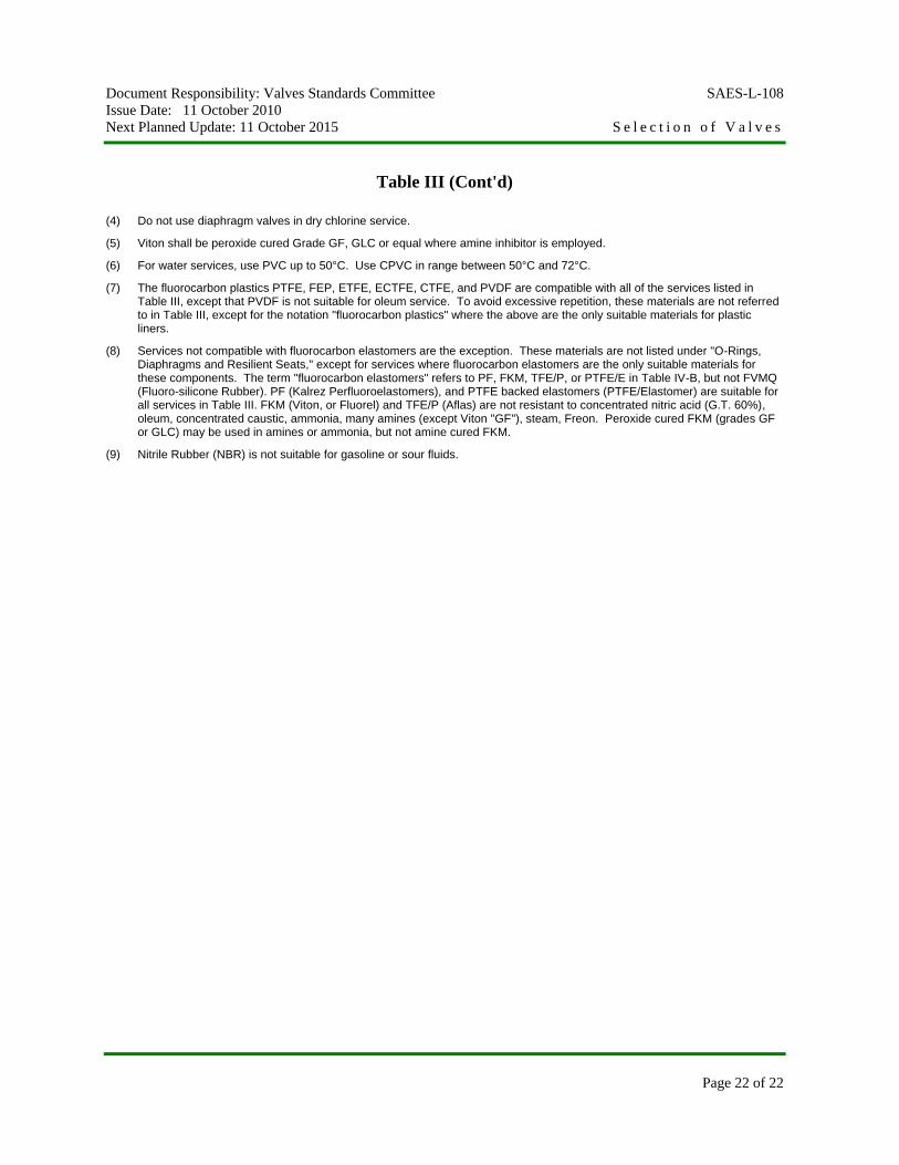
(4) Do not use diaphragm valves in dry chlorine service.
(5) Viton shall be peroxide cured Grade GF, GLC or equal where amine inhibitor is employed.
(6) For water services, use PVC up to 50°C. Use CPVC in range between 50°C and 72°C.
(7) The fluorocarbon plastics PTFE, FEP, ETFE, ECTFE, CTFE, and PVDF are compatible with all of the services listed in Table III, except that PVDF is not suitable for oleum service. To avoid excessive repetition, these materials are not referred to in Table III, except for the notation "fluorocarbon plastics" where the above are the only suitable materials for plastic liners.
(8) Services not compatible with fluorocarbon elastomers are the exception. These materials are not listed under "O-Rings, Diaphragms and Resilient Seats," except for services where fluorocarbon elastomers are the only suitable materials for these components. The term "fluorocarbon elastomers" refers to PF, FKM, TFE/P, or PTFE/E in Table IV-B, but not FVMQ (Fluoro-silicone Rubber). PF (Kalrez Perfluoroelastomers), and PTFE backed elastomers (PTFE/Elastomer) are suitable for all services in Table III. FKM (Viton, or Fluorel) and TFE/P (Aflas) are not resistant to concentrated nitric acid (G.T. 60%), oleum, concentrated caustic, ammonia, many amines (except Viton "GF"), steam, Freon. Peroxide cured FKM (grades GF or GLC) may be used in amines or ammonia, but not amine cured FKM.
(9) Nitrile Rubber (NBR) is not suitable for gasoline or sour fluids.

Document Responsibility: Valves Standards Committee SAES-L-108
Issue Date: 11 October 2010
Next Planned Update: 11 October 2015 S e l e c t i o n o f V a l v e s
Page 23 of 23
Table IVA – Metallic Material Designations
Alloy Designation Description UNS No.
17-4 17-4 PH Stainless Steel S17400 20 Alloy 20 N08020 304 AISI 304 Stainless Steel S30400 304L AISI 304L Stainless Steel S30403 316 AISI 316 Stainless Steel S31600 316L AISI 316L Stainless Steel S31603 410 AISI 410 Stainless Steel S41000 4140 AISI 4140 Steel G41400 600 Inconel 600 N06600 625 Inconel 625 N06625 6NM 13 Cr-4Ni Stainless Steel (Grade CA6NM) (4) J91540 718 Inconel 718 N07718 800 Inconel 800 NO8800 825 Inconel 825 N08825 A286 Precipitation - Hardening Stainless Steel S66286 B-2 Hastelloy B-2 N10665 Br Bronze (See Note 1 and Table IV-B) - C-276 Hastelloy C-276 N10276 CI Gray Cast Iron - CS Carbon Steel - CrMoll 1-1/4 Cr 1/2 Mo Steel J11872 CrMo22 2-1/4 Cr 1 Mo Steel J21890 CrMo5 5 Cr-1/2 Mo Steel J42045 D2 Ductile Ni Resist F43000 DI Ductile Iron -

Document Responsibility: Valves Standards Committee SAES-L-108
Issue Date: 11 October 2010
Next Planned Update: 11 October 2015 S e l e c t i o n o f V a l v e s
Page 24 of 24
Table - IVA (Cont'd)
Alloy Designation Description UNS No. Elg Elgiloy R30003 ENP Electroless Nickel Plating - G-3 Hastelloy G-3 N06985 LTS Carbon Steel for Low Temperature Applications (2) - M400 Monel 400 N04400 MK500 Monel K-500 N05500 MP35N MP35N R30035 N50 Nitronic 50 S20910 NiRe Ni Resist Type 1 F41000 NiRe2 Ni Resist Type 2 F41002 SSS Special Stainless Steels (See Table IV-B) St12 Alloy 12 (Stellite No. 12) R30012 St6 Alloy 6 (Stellite No. 6) R30006 TC Tungsten Carbide - Ti Titanium (Unalloyed) - X750 Inconel X750 N07750
Notes:
(1) Copper alloys shall have 16% or less zinc when used in corrosive aqueous service.
(2) Reference: 04-SAMSS-003.
(3) CA6NM Stainless Steel may be substituted for Type CA15 (AISI 410) for cast valve components.

Document Responsibility: Valves Standards Committee SAES-L-108
Issue Date: 11 October 2010
Next Planned Update: 11 October 2015 S e l e c t i o n o f V a l v e s
Page 25 of 25
Table IVB – Special Stainless Steels and Copper Base Alloys
Alloy Generic, Popular, Designation or Trade Name Form UNS No. Spec or Grade SSS Duplex Stainless (1) Ferralium (A) Wrought S32550 A240 SAF 2507 (A) Wrought S32750 A276, 182 Zeron 100 (A) Wrought S32760 A276, 182 Zeron 100 (A) Cast J93380 Zeron 25 (B) Wrought SAF 2205 (B) Wrought S31803 A182-F51 SAF 2205 (B) Cast J92205 A890-4A CD4MCu (C) Cast J93370 A743, A890 CD4MCu (B) Cast DIN 9.4462 Escoloy (B) Cast J93345 A890-2A Escoloy (B) Cast A890-3A Alloy 958 (A) Cast J93404 A890-5A SSS Superaustenitic AL-6XN (A) Wrought N08366 B675, B690 25-6Mo (A) Wrought B475, B649 1925HMO (A) Wrought N08926 A240, A479 254 SMO (A) Wrought S31254 A182, A312 254 SMO (A) Cast A351 CKMCuN Nitronic 50 (B) Wrought S20910 A479-XM19 904L, 2RK65 (B) Wrought N08904 B625, B649 JS-700 (B) Wrought N08700 B672, B599 IN872, HV-93 (B) Cast A743-CN3M BR Copper Alloys Aluminum Bronze Cast All B148 (2) Aluminum Bronze Wrought C60600 B169 Aluminum Bronze Wrought All B150 Valve Bronze Cast C92200 B61 Ounce Metal Cast C83600 B62 Copper-Silicon Alloy Wrought C65100 B98 Copper-Silicon Alloy Wrought C65500 B98 Copper Alloy Cast C84400 B584 Notes:
(1) SSS alloy rankings for pitting and crevice corrosion resistance are shown in parentheses next to the name, (A) being best. SSS alloys for seawater or sour brine service must be those ranked (A).
(2) ASTM B148 components for seawater service shall receive a temper anneal heat treatment per ASTM B601 Condition "TB".

Document Responsibility: Valves Standards Committee SAES-L-108
Issue Date: 11 October 2010
Next Planned Update: 11 October 2015 S e l e c t i o n o f V a l v e s
Page 26 of 26
Table IVC – Plastics and Elastomers
Material Designation Generic or Trade Names Polymer PLASTICS PVC PVC Polyvinyl Chloride CPVC Chlorinated PVC Chlorinated Polyvinyl Chloride PE Polyethylene Polyethylene PP Polypropylene Polypropylene PVDF Kynar Polyvinylidene-Fluoride FEP Fluorinated Ethylene-Propylene ETFE Tefzel Ethylene-Tefrafluoro Ethylene ECTFE Halar Ethylene-Chlorotrifluoro-Ethylene CTFE Kel-f Chlorotrifluoro-Ethylene PTFE Teflon Poly-Tetrafluoro-Ethylene Nylon Polyamide PVDC Saran Polyvinylidene Chloride CPE Penton Chlorinated Polyether PPS Ryton Polyphenylene Sulfide ELASTOMERS RN Natural Rubber Poly-Isoprene CR Neoprene or Chloroprene Poly-Chloroprene EPDM Nordel, Epcar Ethylene-Propylene IIR Butyl Rubber GR-1 Isobutylene Isoprene NBR Buna-N, Nitrile Rubber, GR-N Butadiene-Acrylonitrile SBR Buna-S, GR-S Styrene-Butadiene CSM Hypalon Chlorosulfonated Polyethylene PTR Polysulfide Rubber Dichlorile-Polysulfide
Document Responsibility: Valves Standards Committee SAES-L-108
Issue Date: 11 October 2010
Next Planned Update: 11 October 2015 S e l e c t i o n o f V a l v e s
Page 27 of 27
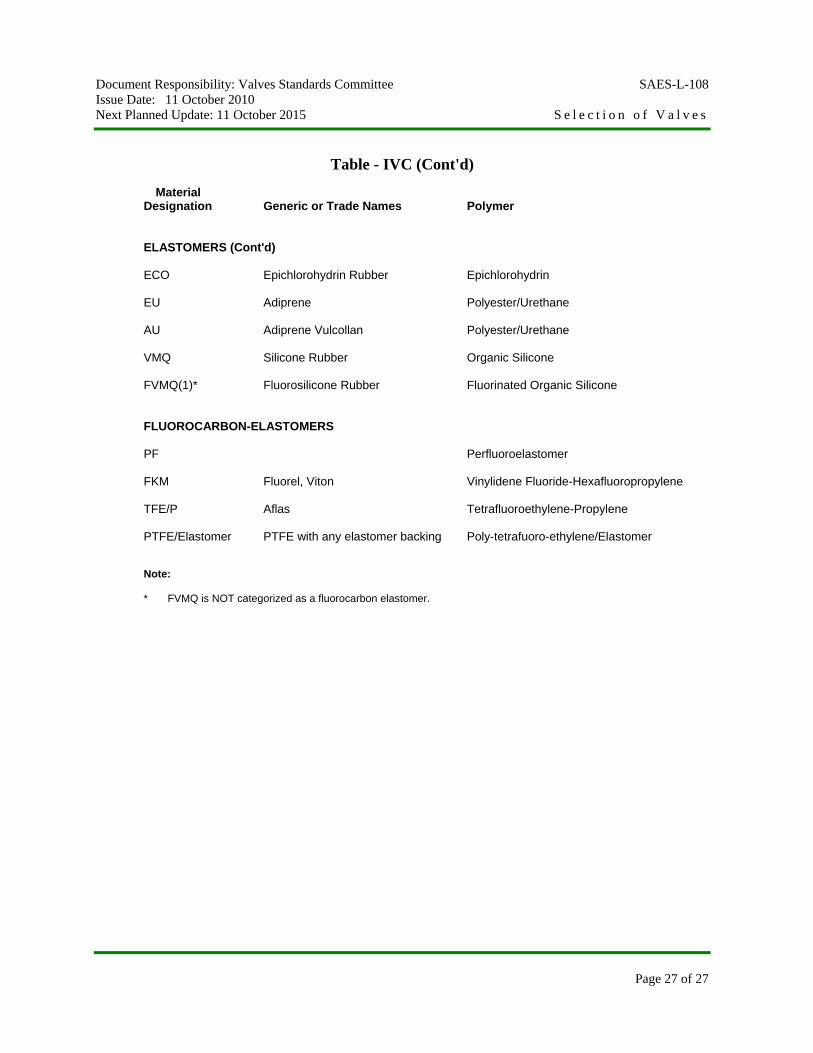
Table - IVC (Cont'd)
Material Designation Generic or Trade Names Polymer ELASTOMERS (Cont'd) ECO Epichlorohydrin Rubber Epichlorohydrin EU Adiprene Polyester/Urethane AU Adiprene Vulcollan Polyester/Urethane VMQ Silicone Rubber Organic Silicone FVMQ(1)* Fluorosilicone Rubber Fluorinated Organic Silicone FLUOROCARBON-ELASTOMERS PF Perfluoroelastomer FKM Fluorel, Viton Vinylidene Fluoride-Hexafluoropropylene TFE/P Aflas Tetrafluoroethylene-Propylene PTFE/Elastomer PTFE with any elastomer backing Poly-tetrafuoro-ethylene/Elastomer
Note: * FVMQ is NOT categorized as a fluorocarbon elastomer.