Embed Size (px)
Citation preview


Faisal Qadeer

Thyristor introduction Thyristor Characteristics Thyristor turn on Thyristor turn off Series and Parallel operation di/dt Protection dv/dt Protection

A thyristor is normally four layer three terminal device. Four layers are formed by alternating n – type and p – type semiconductor materials.
Consequently there are three p – n junctions formed in the device.
It is a bistable device. The three terminals of this device are called
anode (A), cathode (K) and gate (G) respectively.

The gate (G) terminal is control terminal of the device. That means, the current flowing through the device is controlled by electrical signal applied to the gate (G) terminal. The anode (A) and cathode (K) are the power terminals of the device handle the large applied voltage and conduct the major current through the thyristor.
Have the highest power handling capability. It has a rating of 1200V / 1500A with switching
frequencies ranging from 1KHz to 20KHz.

Silicon Controlled Rectifier (SCR)
TRIAC
DIAC

When the anode is at a positive potential VAK with respect to the cathode with no voltage applied at the gate, junctions J1 and J3 are forward biased, while junction J2 is reverse biased. As J2 is reverse biased, no conduction takes place.
Now if VAK is increased beyond the breakdown voltage VBO of the thyristor, avalanche breakdown of J2 takes place and the thyristor starts conducting.
If a positive potential VG is applied at the gate terminal with respect to the cathode, the breakdown of the junction J2 occurs at a lower value of VAK. By selecting an appropriate value of VG, the thyristor can be switched into the on state suddenly.

Reverse breakdown voltage
Holding current
Reverse leakage current
Latching current
Forward volt-drop(conducting)
Forward break-over voltage
Forward leakage current
Gatetriggered
IH
IL
VBO VAK
IT

Thyristors have three states: 1. Reverse blocking mode — Voltage is applied in
the direction that would be blocked by a diode. 2. Forward blocking mode — Voltage is applied in
the direction that would cause a diode to conduct, but the thyristor has not been triggered into conduction.
3. Forward conducting mode — The thyristor has been triggered into conduction and will remain conducting until the forward current drops below a threshold value known as the "holding current"
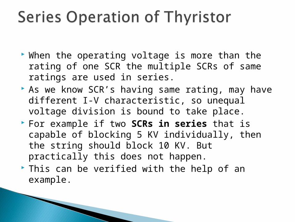
When the operating voltage is more than the rating of one SCR the multiple SCRs of same ratings are used in series.
As we know SCR’s having same rating, may have different I-V characteristic, so unequal voltage division is bound to take place.
For example if two SCRs in series that is capable of blocking 5 KV individually, then the string should block 10 KV. But practically this does not happen.
This can be verified with the help of an example.
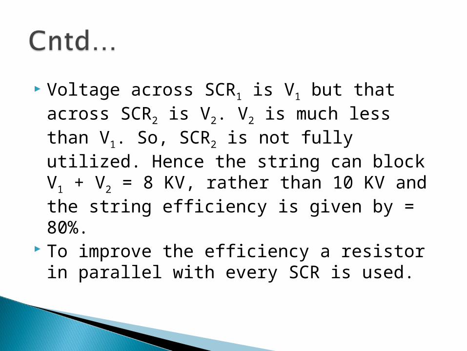
Voltage across SCR1 is V1 but that across SCR2 is V2. V2 is much less than V1. So, SCR2 is not fully utilized. Hence the string can block V1 + V2 = 8 KV, rather than 10 KV and the string efficiency is given by = 80%.
To improve the efficiency a resistor in parallel with every SCR is used.

When the operating current is more than the individual current ratings of SCRs then we use more than one SCRs in parallel.
Due to different V-I characteristics SCRs of same rating shares unequal current in a string.
Let a string consists of two transistors in parallel and their current rating by 1 KA.
From the VI characteristics of the devices it can be seen that for operating volume V, current through SCR1 is 1 KA and that through SCR2 is 0.8 KA. Hence, SCR2 is not fully utilized here.

Though the string should withstand R KA theoretically it is only capable of handling 1.8 KA. So, the string efficiency is = 90%.

When a thyristor is in forward blocking state then only J2 junction is reverse biased which acts as a capacitor having constant capacitance value Cj (junction capacitance). As we know that current through capacitor follows the relation

Hence leakage current through the J2 junction which is nothing but the leakage current through the device will increase with the increase in dva/dt i.e. rate of change of applied voltage across the thyristor.
This current can turn-on the device even when the gate signal is absent.
This is called dv/dt triggering and must be avoided which can be achieved by using Snubber circuit in parallel with the device.

When a thyristor is turned on by gate pulse then charge carriers spread through its junction rapidly.
But if rate of rise of anode current, i.e. di/dt is greater than the spreading of charge carriers then localized heat generation will take place which is known as local hot spots. This may damage the thyristor.
To avoid local hot spots we use an inductor in series with the device as it prevents high rate of change of current through it.


![Power Electronics of Piezoelectric Elements - BGUpel/presentation/Gordon/PZ_3_Slides.pdf · 2 Prof. S. Ben-Yaakov, Power Electronics of Piezoelectric Elements, June 2006 [4] Piezoelectricity](https://img.dokumen.tips/doc/110x75/5a78837f7f8b9aa2448d0950/power-electronics-of-piezoelectric-elements-pelpresentationgordonpz3slidespdf2.jpg)