Embed Size (px)
Citation preview

Topic: owen’s bridge and measurement of increment inductance.
Owen’s bridge:

parameters of bridge :L1 = unknown inductance having its resistance R1
R2 = variable non inductive resistance
R3 = fixed non inductive resistance
C2 = variable standard capacitor
C4 = fixed standard capacitor

Use of own’s bridge
The own’s bridge use for the measurement of inductance is expressed in the terms of capacitance

For A.C. bridges the balancing condition for bridge is
Z1 Z4 = Z2 Z3Z1 = ( R1 + jω L1 )
Z2 = R2 +
Z3 = R3
Z4 =

Z1 Z4 = Z2 Z3
comparing real terms;

Comparing imaginary terms

Phasor diagram:

Measurements Of Incremental InductanceThe magnetic flux linking an ion-cored coil is not in direct
proportion to the current flowing in the coil, but varies in manner usually indicated by a magnetization curve. The flux usually increases fairly rapidly when the current build-up process first begins.
The flux increment to a particular size of current increment becomes smaller with continual increase of current as the core approaches saturation.

An induced voltage in the coil depends on a change of flux and hence becomes smaller for a given current change at higher values of current.
The basic expression for induced voltage in terms of a changing flux is usually replaced by the coefficient of self inductance multiplied by the rate of change of current.
Effect On Induced Voltage.

In terms of a flux change, the induced voltage is
ℓ= -Ndф/dt.In terms of inductance, ℓ= -Ldi/dt where; L= coefficient of self inductance.Comparison of the two expressions gives L=Ndф/diWhich helps to explain the nature of this quantity. Inductance may
be repesented by the slope of the ф-i magnetization curve of a reactor.
For an air-cored coil there is a linear relationship between flux and current hence L is a constant.
For an iron-cored coil there is no linear flux-current relationship hence L has different values depending on the portion of magnetization curve being used and on the manner of defining L.
Many iron cored coils are used as filter reactors in rectifier circuits and in other applications.
Description Of Ø-i Magnetizing Curve
The incremental inductance at this point may be defined a square of turns multiply the slope of the ф-i curve.
Therefore, Incremental inductance L= N² dф/di
Similarly incremental permeability may be defined as the slope of the B-H curve at the operating point.
Therefore, Incremental permeability μ = dB/dH
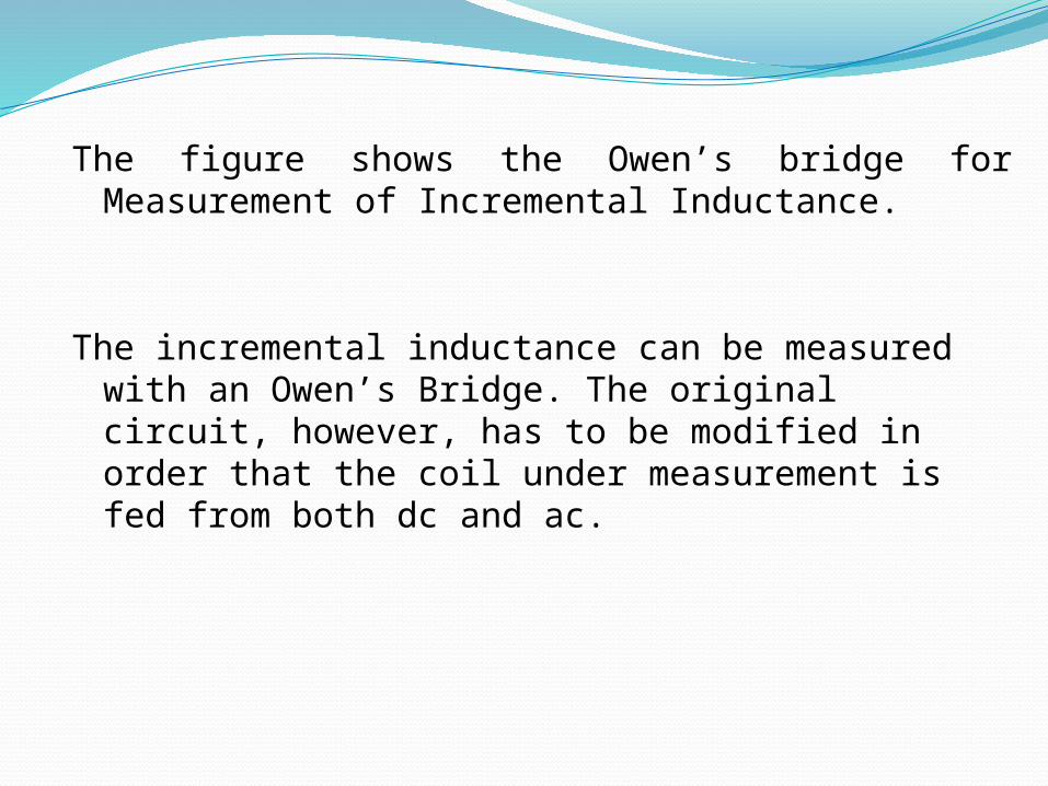
The figure shows the Owen’s bridge for Measurement of Incremental Inductance.
The incremental inductance can be measured with an Owen’s Bridge. The original circuit, however, has to be modified in order that the coil under measurement is fed from both dc and ac.

Diagram Of Increment Inductance.

• The coil is fed from ac and dc sources in parallel. A blocking capacitor C, is used to block direct current from entering the ac source.
• A high inductance L, is used to block alternating current to
enter dc source. Any direct current must not affect the balance and this condition is automatically satisfied in owen’s bridge because capacitors C2 and C4 block any dc current flowing through the detector.

Dc component of current is measured by a moving coil ammeter A connected in the dc supply circuit.
Ac component of current can be obtained from the reading of a valve voltmeter connected across R3.
The value of current calculated from this readind is ac current through R3, but this is also the ac current through the coil at balance.

At balance, incremental inductance
L1 = N²/(l/μA) μ= L1l/N²A
Where; N= number of turns l= length of flux path A= area of flux path L1=incremental inductance

Thank you


![Brainf*ck Lexical Analysis - GitHub Pages€¦ · Brainf*ck Lexical Analysis Program: ++[>+[+]]. Program Tokens: INCREMENT INCREMENT LOOP_HEADER MOVE_RIGHT INCREMENT LOOP_HEADER INCREMENT](https://img.dokumen.tips/doc/110x75/5f98faba31b4de6080596e95/brainfck-lexical-analysis-github-pages-brainfck-lexical-analysis-program-.jpg)