Embed Size (px)
Citation preview

Alexandria UniversityFaculty of Engineering
Application of Line Heating Method In Shipbuilding Industry
1
”تطبيق طريقة التسخين الخطى فى صناعة بناء السفن “
9-Apri-2009
Submitted by
Engr. Kamal Hassan Kamal Mohamed
Supervisors
Prof. Dr. Ahmed El-BadanProf. Dr. Ahmed Mohamed Rashwan
Naval Architecture & Marine Engineering DepartmentFaculty of EngineeringAlexandria University
Submitted: April 2009

THESIS OUTLINES1. INTRODUCTION
2
2. AIM OF THE STUDY
3. THE PRINCIPLES OF HEATING OF METALS
4. PARAMETERS AFFECTING PERMANENT DEFORMATIONS
5. LINE HEATING FORMING PROCEDURES
6. EXPERIMENTS VERIFICATION
7. CONCLUSION
8. RECOMMENDATIONS FOR FUTURE WORK
9-Apri-2009

1. INTRODUCTION
1. Quicker and more accurate than methods using heavy machinery.
2. Build much more complicated shapes with only minor investment in new equipment.
3
Line Heating Advantages:Line Heating
Press
Roller
9-Apri-2009

2. AIM OF THE STUDY
To build a scientific practical guide informing flat plates to certain shapesby Line Heating Method.
49-Apri-2009
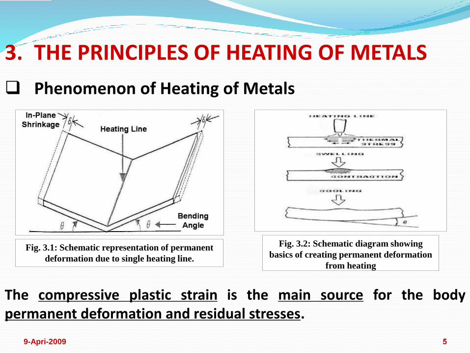
3. THE PRINCIPLES OF HEATING OF METALS
Phenomenon of Heating of Metals
Fig. 3.2: Schematic diagram showing
basics of creating permanent deformation
from heating
Fig. 3.1: Schematic representation of permanent
deformation due to single heating line.
The compressive plastic strain is the main source for the body permanent deformation and residual stresses.
59-Apri-2009

These simple examples suggest the following:1. The shrinkage is important to form a spherical shape which has
curvatures in two directions.2. The bending angle is necessary to create cylindrical shape which has
unidirectional curvature.
Line Heating Idea
Fig. 3.3: Forming of cylinder shape Fig. 3.4: Forming of shallow spherical shell shape
69-Apri-2009

4. PARAMETERS AFFECTING PERMANENT DEFORMATIONS Maximum Heating Surface Temperature
79-Apri-2009

Fig. 4.1: Bending angle as a function of heat input power [10]
8
Effective Heat Input Power
9-Apri-2009

Plate Thickness and Heating Torch Travel Speed
Torch Tip-Plate Separation
Fig. 4.2: Torch tip-plate separation detail 99-Apri-2009

Fig. 4.3: Bending angle obtained with no
initial stress (0 N/mm2) [4]
Fig. 4.4: Bending angle obtained with
initial stress (-80 N/mm2) [4]
Fig. 4.5: Bending angle obtained with
initial stress (-160 N/mm2) [4]
Initial Stress
109-Apri-2009

Cooling Method
Fig. 4.6: Cooling on the heated side of steel plate.
Fig. 4.7: Cooling on the back side
of steel plate
119-Apri-2009

5. LINE HEATING FORMING PROCEDURES
Fig. 5.1: Usual Different Forms of Curved Plates in Ship Structure
129-Apri-2009

a) Single Curvature Shape
Constant Curvature Shape in Transverse Direction without Twist
Fig. 5.2: Constant Curvature Shape in the
Transverse Direction without Twist
Fig. 5.3: Heating Application Sequence
Constant Curvature Shape in the Transverse
Direction without Twist139-Apri-2009

Constant Curvature Shape in Transverse Direction with Twist
Fig. 5.4: Constant curvature shape in
the transverse direction with twist
Fig. 5.5: Heating application sequence
for constant curvature shape in the
transverse direction with twist149-Apri-2009

Variable Curvature Shape in Transverse Direction
Fig. 5.6: Variable curvature shape in the transverse direction
159-Apri-2009

b) Double Curvature Shape in the Same Direction of thePlate Surface – Longitudinal Concave Curvature Shape(Pillow Shape)
Fig. 5.27: Longitudinal concave
curvature shape (Pillow Shape)
169-Apri-2009

Longitudinal Concave Curvature Shape without Twist
Stage 1 Stage 2
22
22
2
Tradrad
T
Trad
T
rad
hy
hWNOHL
hy
hWNOHL
R
WNOHL
22
22
481.0
4
481.0
4
LTT
TL
LT
TL
hL
hhLNOHT
hL
hhLNOHT
(Eq. 4.1)(Eq. 4.3)
Fig. 5.8: Heating application sequence for longitudinal concave
curvature without twist 179-Apri-2009

Longitudinal Concave Curvature Shape with Twist
Stage 1 Stage 2
22
1
22
1
1
2
Tradrad
T
Trad
T
rad
hy
hWNOHL
hy
hWNOHL
R
WNOHL
22
22
481.0
4
481.0
4
LTT
TL
LT
TL
hL
hhLNOHT
hL
hhLNOHT
(Eq. 4.2) (Eq. 4.3)
Fig. 5.9: Heating Application Sequence for longitudinal
concave curvature with twist 189-Apri-2009

c) Reverse Double Curvature Shape – Longitudinal convexcurvature Shape (Saddle Shape)
Fig. 5.10: Longitudinal convex curvature shape
Fig. 5.11: Line heating technique details for forming the longitudinal convex curvature shape (Saddle shape)
199-Apri-2009

Longitudinal Convex Curvature Shape without Twist
Stage 1
22
22
481.0
4
481.0
4
LLL
TL
LL
TL
hL
hhLNOHL
hL
hhLNOHL
(Eq. 4.1) (Eq. 4.4)
22
22
2
Tradrad
T
Trad
T
rad
hy
hWNOHL
hy
hWNOHL
R
WNOHL
Stage 2
Fig. 5.12: Heating sequence for longitudinal convex curvature shape without twist209-Apri-2009
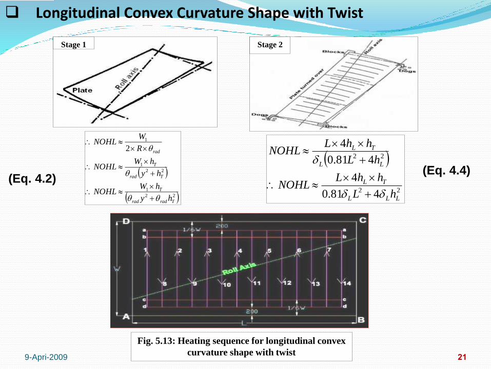
Longitudinal Convex Curvature Shape with Twist
Stage 1
22
1
22
1
1
2
Tradrad
T
Trad
T
rad
hy
hWNOHL
hy
hWNOHL
R
WNOHL
22
22
481.0
4
481.0
4
LLL
TL
LL
TL
hL
hhLNOHL
hL
hhLNOHL
Stage 2
(Eq. 4.2)(Eq. 4.4)
Fig. 5.13: Heating sequence for longitudinal convex
curvature shape with twist219-Apri-2009
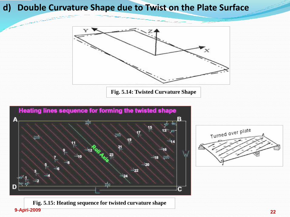
d) Double Curvature Shape due to Twist on the Plate Surface
Fig. 5.14: Twisted Curvature Shape
Fig. 5.15: Heating sequence for twisted curvature shape
229-Apri-2009

Line Heating Tools
Line Heating Workstation
23
6. EXPERIMENTS VERIFICATION
9-Apri-2009

24
Modals Dimensions & Line Heating Conditions
9-Apri-2009

259-Apri-2009

26
Experiments of Single Curvature Shape1. Constant Curvature Shape in Transverse Direction without Twist
(Expr.1) Plate Dims. 12X4060X1789 mm.
9-Apri-2009

Fig. 6.1: The result of Experiment No. 1279-Apri-2009
28
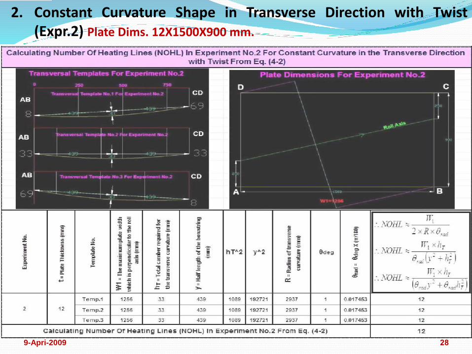
2. Constant Curvature Shape in Transverse Direction with Twist (Expr.2) Plate Dims. 12X1500X900 mm.
9-Apri-2009
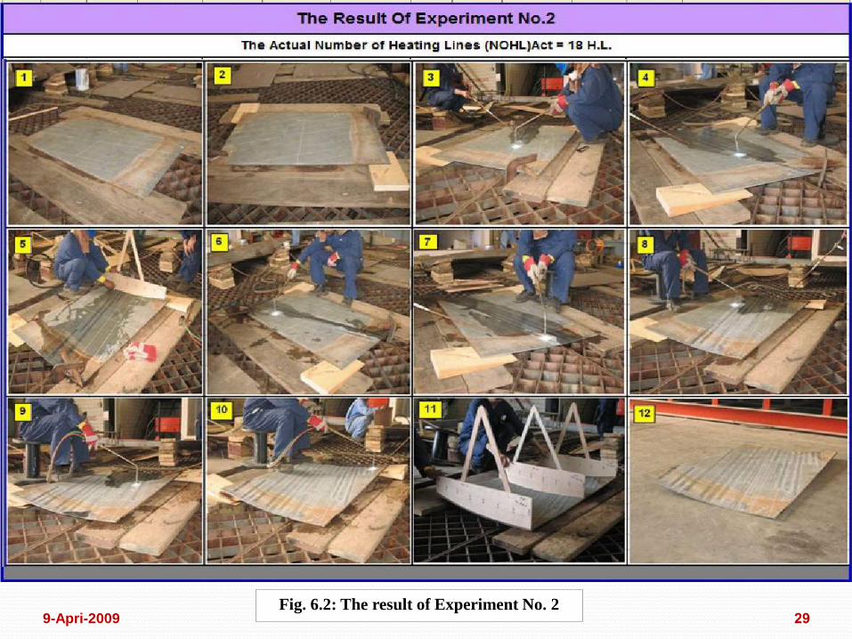
Fig. 6.2: The result of Experiment No. 2299-Apri-2009

30
3. Variable Curvature Shape in Transverse Direction (Expr.3) Plate Dims.
10X3000X(820+720) mm.
9-Apri-2009

Fig. 6.3: The result of Experiment No. 3 Part (1) 319-Apri-2009
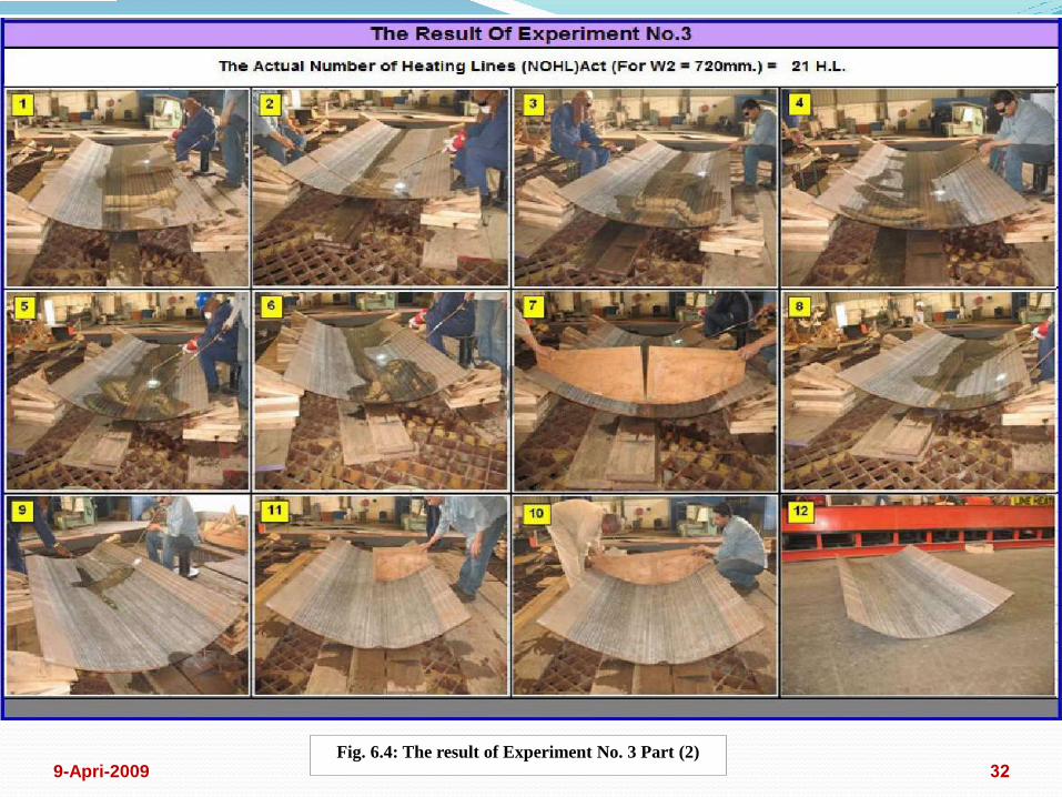
Fig. 6.4: The result of Experiment No. 3 Part (2)329-Apri-2009

33
1. Longitudinal Concave Curvature Shape without Twist (Expr.4) Plate Dims. 10X1500X900 mm.
Experiments of Double Curvature Shape in the SameDirection of the Plate Surface (Pillow Shape)
9-Apri-2009

349-Apri-2009

Fig. 6.5: The result of Experiment No. 4359-Apri-2009

36
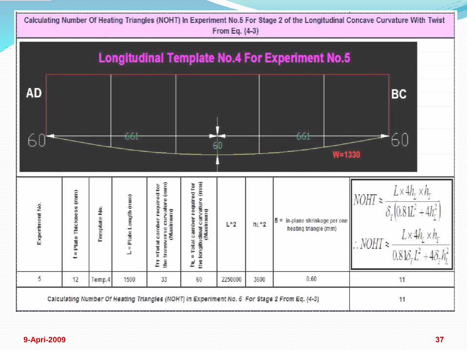
2. Longitudinal Concave Curvature Shape with Twist (Expr.5) Plate Dims. 12X1500X900 mm.
9-Apri-2009
379-Apri-2009

Fig. 6.6: The result of Experiment No. 5389-Apri-2009

39
Experiments of Reverse Double Curvature Shape (SaddleShape)
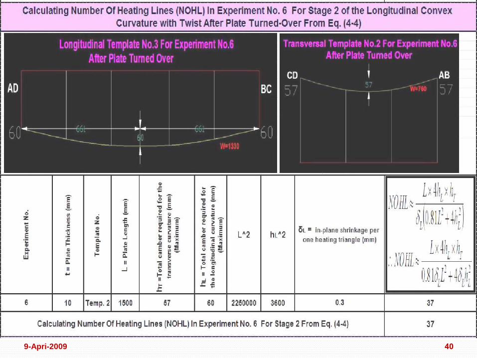
1. Longitudinal Convex Curvature Shape without Twist (Expr.6) Plate Dims. 10X1500X870 mm.
9-Apri-2009
409-Apri-2009

Fig. 6.7: The result of Experiment No. 6419-Apri-2009

42
2. Longitudinal Convex Curvature Shape with Twist (Expr.7) Plate Dims.
12X1500X900 mm.
9-Apri-2009
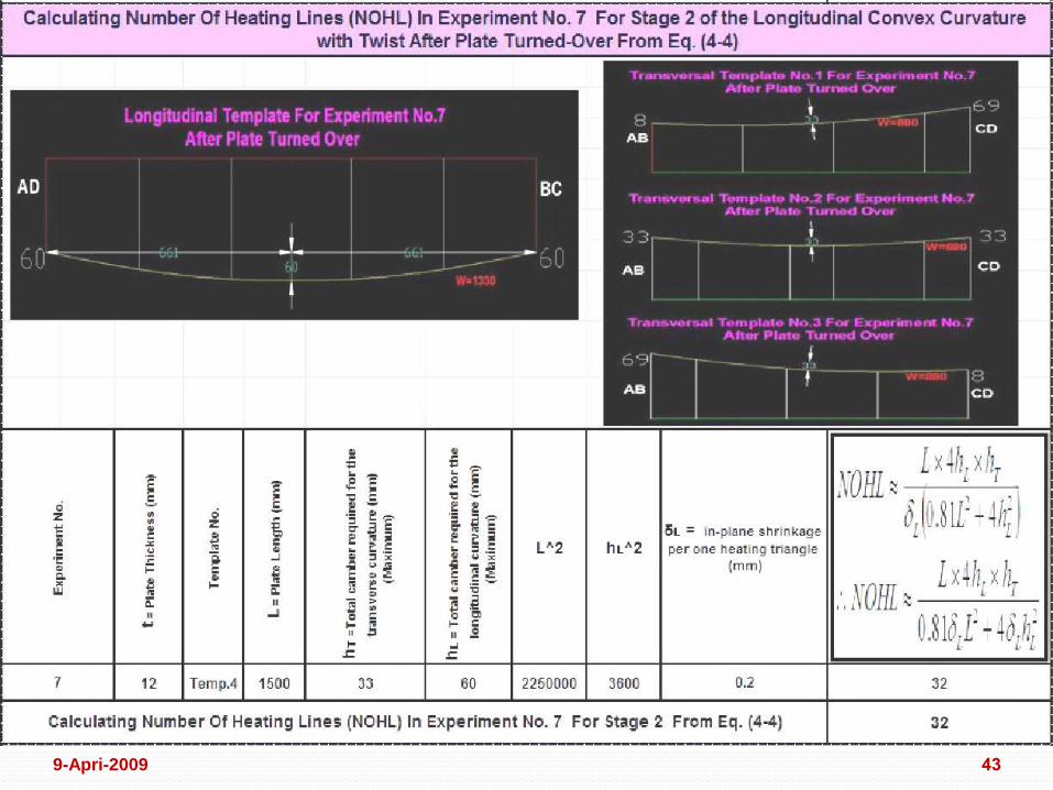
439-Apri-2009

Fig. 6.8: The result of Experiment No. 7449-Apri-2009

45
Experiments of Double Curvature Shape due to Twist on the Plate Surface (Expr.8) Plate Dims. 10X5343X2283 mm.
9-Apri-2009

Fig. 6.9: The result of Experiment No. 8469-Apri-2009

7. CONCLUSION
47
8. RECOMMENDATIONS FOR FUTURE WORK
9-Apri-2009

?
QUESTIONS
489-Apri-2009

499-Apri-2009

THANK YOU
509-Apri-2009


![[MASTER THESIS] - Universiteit Twenteessay.utwente.nl/62792/1/Master_thesis_Ivo_Schutz_-_NedMobiel.pdf · this master thesis. First and most of all my gratitude goes to Maarten Hellemans,](https://img.dokumen.tips/doc/110x75/5afd639c7f8b9a814d8d6b2b/master-thesis-universiteit-master-thesis-first-and-most-of-all-my-gratitude.jpg)