Embed Size (px)
Citation preview

INDUSTRIAL TRAINING RE PO RTo n
“ READY MIX CONCRETE & PODIUM WORKS “
at
MY HOME VIHANGA
SUBMITTED IN PARTIAL FULFILLMENT OF THE REQUIREMENT FOR
THE AWARD OF DIPLOMA
IN
CIVIL ENGINEERINGby
P.KRUPAKAR RAO 13253-C-023
2nd SHIFT POLYTECHNIC
DIPLOMA IN CIVIL ENGINEERING
VALLURUPALLI NAGESWARA RAO
VIGNANA JYOTHI INSTITUTE OF ENGINEERING AND TECHNOLOGY
VIGNANA JYOTHI NAGAR, BACHUPALLY, NIZAMPET (S. O),
HYDERABAD - 500 090
2015 – 2016

2n d SHIFT POLYTECHNICVALLURUPALLI NAGESWARA RAO VIGNANA JYOTHI
INSTITUTE OF ENGINEERING & TECHNOLOGY(Approved By A.I.C.T.E., New Delhi and S.B.T.E.T, A.P.)
Vignana Jyothi Nagar, Bachupally, Nizampet (S.O), Hyderabad – 500 090, A.P. India.Tel: +91-40-23042758, 23042759, 23042760 Fax: 91-40-23042761
E-mail: [email protected]. Website: www.vnrvjiet.ac.inEstd. 2009
Diploma in Civil Engineering
CERTIFICATE
This is to certify that the “INDUSTRIAL TRAINING REPORT” being submitted by P.KRUPAKAR RAO ,13253-C-023 in partial fulfillment for the award of DIPLOMA in CIVIL ENGINEERING to the State Board of Technical Education and Training, Hyderabad at 2n d SHIFT POLYTECHNIC VALLURUPALLI NAGESWARA RAO VIGNANA JYOTHI INSTITUTE OF ENGINEERING & TECHNOLOGY,HYDERABAD, is a record of bonafide work carried out by him under our guidance and supervision.
Mrs. K.SreevalliIndustrial Training Co-ordinator
Ms. U.Pallavi
Incharge DCE

APPROVAL CERTIFICATE
Industrial Training assessment for the Industrial Training work being submitted by
P.KRUPAKAR13253-C-023
is conducted on … … … … … … … and the work is approved for the
award of DIPLOMA IN CIVIL ENGINEERING.
INTERNAL EXAMINER EXTERNAL EXAMINER


5
ACKNOWLEDGEMENT
It has been great honour and privilege to undergo training at MY HOME
CONSTRUCTIONS, Hyderabad. I am very much thankful to the Mr. Ramesh Mantha
(Director projects), Mr.Dayakar (General Manager), Mr. M.Vijay Kumar (DGM), Mr.
Rajashekar (Manger podiums) & Mr. Prasad (H.R) and all the Engineer staff of MY
HOME CONSTRUCTIONS (My Home Vihanga Project) for providing all facilities and
support to meet my project requirements under whom I executed this work. His constant
guidance and willingness to share his vast knowledge made me understand this work and its
manifestations in great depths and helped me to complete the assigned task and my special
thanks to my College Guide Ms. K.Sreevalli (Civil Dept.) & Incharge Ms. U.Pallavi(Civil
Dept.) for sharing their knowledge and helping me throughout the task.
I extend my gratitude to my Principal whose guidance is never forgettable and gave me
inspiration to complete the internship program successfully.

6
INDEXSL NO CONTENTS Pg no
1 INTRODUCTION 08-08
2 CONSTRUCTION PROJECT SITE 09-09
3 READY MIX CONCRETE 10-13
4 ADMIXTURES 14-17
5 CONCRETE WORKS 18-24
6 CONCRETE TESTING 25-28
7 R.C.C FOOTINGS
28-30
8 COLUMN STARTERS
31-31
9 COLUMN AND BEAM 31-33
10 SLABP.T SLABR.C.C SLAB
33-41
11SHEAR WALLS
41-44
12 FORM WORK :MAINI AND MIVANTECHNOLOGIES (SHUTTERING)
45-48

7
13 BRICK WORK 49-52
14 SAFETY 53-54
15 SITE IMAGES 55-57
16 CONCLUSION 58-58

8
INTRODUCTIONAbout Organisation:
My home group is a fast growing conglomerate headquartered at Hyderabad. It has diversified large scale business interest in cement Production, construction of Residential and commercial complexes, Power generations, Manufacturing fly ash bricks, Ready mix concrete, Transportation, Road works, Power, High yield horticulture, Education, etc. In the state of Telangana.
An integral part of My home group, My home constructions Pvt. Ltd. has had a successful innings in real estate sector in Hyderabad for over 2 decades.
Project Description - My Home Vihanga:
My Home Vihanga, The Hyderabad city's most beautiful and luxurious apartments launched in 2014 and will be completed in 2017. The project is spread across 21 acres of site area with 20 blocks.
My Home Vihanga Project Specification's:
The 21-acre mega project houses with 1996 apartments measuring 1115 ft to 2160 ft in area.
This project is constructed with RCC shear wall-framed structure, resistant to wind and earthquake (Zone — 2).
The Three construction contract-based companies handling this VIHANGA project
S.V.S projects
K.L.C constructions
B.S.R infra
CQRA (Construction Quality Rating Agency) is the 3rd part for Quality Assurance in My Home Vihanga
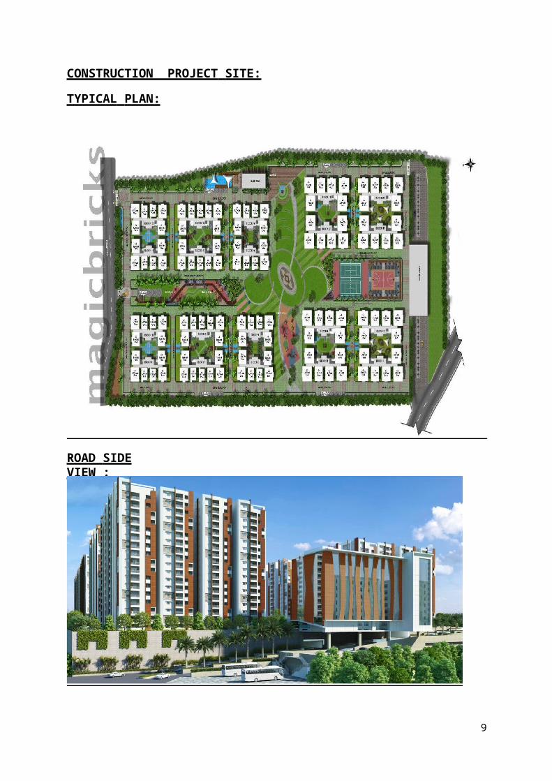
CONSTRUCTION PROJECT SITE:
TYPICAL PLAN:
ROAD SIDE VIEW :
9

10
READY MIX CONCRETE (RMC):
CONCRETE: It is a construction material made of mixture of Cement, Fine aggregate, Coarse aggregate and Water.
Ready-mix concrete is concrete that is manufactured in a factory or batchingplant, according to a set recipe, and then delivered to a work site, by truck mounted in–transit mixers. This results in a precise mixture, allowing specialty concrete mixtures to be developed and implemented on constructionsites. Ready-mix concrete is sometimes preferred over on-site concrete mixing because of the precision of the mixture and reduced work site confusion. However, using a pre-determined concrete mixture reduces flexibility, both inthe supply chain and in the actual components of the concrete.
Merits of RMC:
Better quality concrete is produced.
Elimination of storage space for basic materials at site.
Elimination of procurement/hiring of plant and machinery
Wastage of basic materials is avoided.
Labour associated with production of concrete is eliminated.
Time required is greatly reduced.
Noise and dust pollution at site is reduced.
Organization at site is more streamlined.
Durable & affordable.
No storage space required either for raw materials or for the mix.
Lower labour and supervisory cost.
No wastage at site.
Environment friendly.
Availability of concrete of any grade.Demerits of RMC:
Not suitable for small projects, where the concrete works areconsiderably low.
Requires huge initial investment. Cannot be effective if there is no proper transportation of the concrete.

INGREDIENTS OF CONCRETE: Cement Fine aggregate Coarse aggregate Water
CEMENT: It is a binding material made by grinding of lime stone and clay to a fine powder, which can be mixed with water and poured to set as a solid mass or used as a ingredient in making mortar or concrete.
Specific gravity of cement is 3.15.
TYPES OF CEMENT:
The types of are as follows.
1.43 Grade ordinary Portland cement conforming to IS 8112.
2. 53 Grade ordinary Portland cement conforming to IS 12269 (used at site).
3.Rapid hardening Portland cement
conforming to IS 8041.
4 .Portland slag cement
conforming to IS 455.
5. Portland pozzolana cement (Fly ash based) conforming
to IS 1489 (part 1). 6.Portland pozzolana cement
(Calcined clay based ) conforming to IS 1489 (part 2).
7. Hydrophobic cement conforming to IS 8043.
8 .Low heat Portland cement conforming to IS 12600.
9. Sulphate resisting Portland cement conforming to IS 12330.
ORDINARY PORTLAND CEMENT(OPC):Name Portland is due to resemblance of colour and quality of the set cement to Portland stone, a limestone quarried in a place Dorset in UK.
Composition of Ordinary Portland Cement:The ordinary Portland cement mainly contains calcium oxide, silicon dioxide, aluminium trioxide.The approximate percentage composition of an ordinary Portland cement is present in the table.
Chemical Composition of Ordinary Portland Cement
CONCRETE: It is a construction material made of mixture of Cement, Fine aggregate, Coarse aggregate and Water.
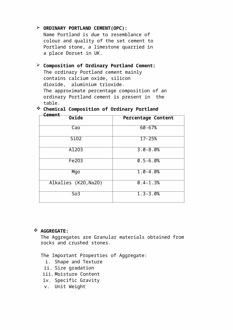
Oxide Percentage Content
Cao 60-67%
SiO2 17-25%
Al2O3 3.0-8.0%
Fe2O3 0.5-6.0%
Mgo 1.0-4.0%
Alkalies (K2O,Na2O) 0.4-1.3%
So3 1.3-3.0%
AGGREGATE:The Aggregates are Granular materials obtained from rocks and crushed stones.
The Important Properties of Aggregate:i. Shape and Texture
ii. Size gradationiii. Moisture Contentiv. Specific Gravityv. Unit Weight
ORDINARY PORTLAND CEMENT(OPC):Name Portland is due to resemblance of colour and quality of the set cement to Portland stone, a limestone quarried in a place Dorset in UK.
Composition of Ordinary Portland Cement:The ordinary Portland cement mainly contains calcium oxide, silicon dioxide, aluminium trioxide.The approximate percentage composition of an ordinary Portland cement is present in the table.
Chemical Composition of Ordinary Portland Cement
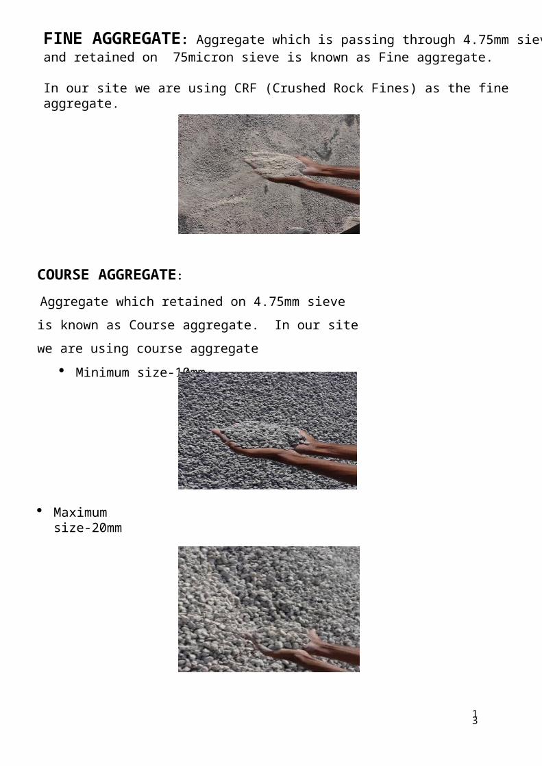
COURSE AGGREGATE:
Aggregate which retained on 4.75mm sieve is known as Course
aggregate. In our site we are using course aggregate
Minimum size-10mm.
Maximum size-20mm
13
FINE AGGREGATE: Aggregate which is passing through 4.75mm sieve and retained on 75micron sieve is known as Fine aggregate.
In our site we are using CRF (Crushed Rock Fines) as the fine aggregate.

10
ADMIXTURE:
An Ingredient other than cement, aggregate, water that is added to the concrete or mortar mix to effect the physical or chemical characteristics of the concrete or mortar. The most common admixtures effects air entertainment plasticity and curing time.
Admixtures are of 2 types
1. Mineral admixtures 2.Chemical admixtures
MINERAL ADMIXTURES:
A substance added to concrete as both a “filler, “improving the physical structure by occupying the spaces between cement particles, and as a “pozzolana”,reacting chemically to impart far greater strength and durability.
In Vihanga site we use GGBS as Mineral Admixtures.
GGBS (Ground Granulated Blast Furnace slag)
GGBS (Ground Granulated Blast Furnace slag):
GGBS is obtained during the steel making process. When the slag is quenched to form granules. GGBS is the by product obtained in the manufacture of pig iron in blast furnace at 1400-1500`c in the molten form. The cost of GGBS is high when compared to FLYASH.
In our site RMC Plants 1&2 we are using Flyash and in plant 3 we use GGBS as a mineral admixtures.
Typical chemical composition:Calcium oxide -
40%Silica -
35%Alumina -
13%Magnesia -
8%Typical physical properties:
Colour
Specific gravity
Bulk density
Fineness
-
-
-
-
off-white
2.9
1200 kg per cubic meter
>350 sq. meter per kg

15
Working with Ground Granulated Blast furnace Slag (GGBS) Concrete:
Water Demand
GGBS allows for water reduction of 3 to 5% in concrete without any loss in workability. Water should not be added to GGBS concrete after dispatch from the concrete plant as it reduces strength and durability of the concrete.
Placing, Compacting and Pumping
GGBS makes concrete more fluid, making it easier to place into form work and easier to compact by vibration. GGBS concrete remains workable for longer periods allowing more time for placing and vibrating. Pumping is also easier due to the better flow characteristics. Concrete with 50% GGBS
Strength development
GGBS concrete has slightly slower strength development at early ages, but will have equal if not greater strength at 28 days compared ton on GGBS concrete. At 7 days GGBS concretes will have 50 to 60% of its characteristic strength compared to 70 to 80% for Portland cement only concrete at the same time. At 28 days GGBS concrete will have fully developed its characteristic strength and will continue to develop strength past 90 days. It is good practice to make 56 day cubes when using GGBS concrete at 50% and above should there be any concern over later strength development.
Setting Times
The initial setting time of concrete is dependent on the concrete’s constituents, curing conditions and its application use. Concrete with up to 30% GGBS will exhibit similar initial setting as concrete with Portland cement only. At replacement levels of 40 to 50% the initial set is likely to be extended by one to two hours and for concrete containing more than 50% GGBS setting time maybe extended past three hours.
Longer setting times can have the advantage of allowing concrete to be worked for longer periods meaning time delays, including delays in transport, between mixing and using concrete are less critical. They also reduce the risk of cold joints in larger concrete pours.

16
CHEMICAL ADMIXTURES:
Chemical admixtures are the ingredients in concrete other than portland cement, water, and aggregate that are added to the mix immediately before or during mixing. Producers use admixtures primarily to reduce the cost of concrete construction; to modify the properties of hardened concrete; to ensure the quality of concrete during mixing, transporting, placing, and curing; and to overcome certain emergencies during concrete operations.
Types of chemical admixtures:
Admixtures are classed according to function. There are five distinct classes of chemical admixtures: air-entraining, water-reducing, retarding, accelerating, and plasticizers (superplasticizers).
Water-reducing admixtures: usually reduce the required water content for a concrete mixture by about 5 to 10 %. Consequently, concrete containing a water-reducing admixture needs less water to reach a required slump than untreated concrete. The treated concrete can have a lower water-cement ratio. This usually indicates that a higher strength concrete can be produced without increasing the amount of cement. Recent advancements in admixture technology have led to the development of mid-range water reducers. These admixtures reduce water content by at least 8 % and tend to be more stable over a wider range of temperatures. Mid-range water reducers provide more consistent setting times than standard water reducers.
Retarding admixtures: which slow the setting rate of concrete, are used to counteract the accelerating effect of hot weather on concrete setting. High temperatures often cause an increased rate of hardening which makes placing and finishing difficult. Retarders keep concrete workable during placement and delay the initial set of concrete. Most retarders also function as water reducers and may entrain some air in concrete.
Accelerating admixtures: increase the rate of early strength development, reduce the time required for proper curing and protection, and speed up the start of finishing operations.Accelerating admixtures are especially useful for modifying the properties of concrete in cold weather.
Superplasticizers: also known as plasticizers or high-range water reducers (HRWR), reduce water content by 12 to 30 percent and can be added to concrete with a low-to-normal slump and water-cement ratio to make high-slump flowing concrete. Flowing concrete is a highly fluid but workable concrete that can be placed with little or no vibration or compaction. The effect of superplasticizers lasts only 30 to 60 minutes, depending on the brand and dosage rate, and is followed by a rapid loss in workability. As a result of the slump loss, superplasticizers are usually added to concrete at the jobsite.

17
Corrosion-inhibiting admixtures: fall into the specialty admixture category and are used to slow corrosion of reinforcing steel in concrete. Corrosion inhibitors can be used as a defensive strategy for concrete structures, such as marine facilities, highway bridges, andparking garages, that will be exposed to high concentrations of chloride. Other specialty admixtures include shrinkage-reducing admixtures and alkali-silica reactivity inhibitors. The shrinkage reducers are used to control drying shrinkage and minimize cracking, while ASR inhibitors control durability problems associated with alkali-silica reactivity.
Two types of Chemical Admixtures Used In our site.
1. CHRYSO
2. ADVA PC 960
In the design of SCC (self compacted concrete) we are not use CHRYSO Admixture.
In the design of Regular concrete we are use the both CHRYSO and ADVA PC 960.
CHRYSO is economically high when compared with the ADVAPC 960.
ADVA:
The ADVA is of high range water reducer is based on a range of new polycarboxylate molecules, which have been specially designed for use as cement dispersants.

CONCRETE WORKS:
TRANSPORTING AND PLACEING:
VIBRATION:
The most commonly used vibrator. It essentially consists of a steel tube having an eccentric vibrating element inside it. This steel tube called poker is connected to an electric motor or a diesel engine through a flexible tube. They are available in size varying from 40 to 100 mm diameter. The diameter of the poker is decided from the consideration of the spacing between the reinforcing bars in the form-work. The frequency of vibration varies upto 15000 rpm.However a range between 3000 to 6000 rpm is suggested as a desirable minimum with an acceleration of 4g to 10g.
18

CONCRETE FINISHING :
Screeding (Strike off)
Screeding is the process of cutting off excess concrete to bring the top surface of a slab to proper grade.
CURING:
A newly placed and finished concrete should be cured protected from drying, extreme changes in temperature, and damage.
The curing should begin immediately after finishing.
CRUSH:
In this image the raw materials which are needed for weigh batching are deposited at one side of the batching plant which will grabbed from crane at batching plant only.
FILLING OF CEMENT SILO:
Cement silos are filled by loaded truck of cement by pumping.
19

The truck in the image carries cement and its capacity is 21 tonnes. And also higher capacity of truck carries cement of 32 tonnes. Cement being pumped to cement silos by truck in the above image.
Concrete can be mixed at jobsite in a stationary mixer:
The circular which seen in this image is the mixer of weigh batched dry materials of concrete the water and admixtures is directly added to that barrel from separate pipe connection, it will be automatically weighed and mixed well.
Central mixing in a stationary mixer of the tilting type with a delivery by a truck mixer operating at agitated speed:
20

1) Truck-mixed concrete mixed completely in truck mixer.
2) Mobile batcher measures material by volume and continuously mixes concrete as the dry ingredients, water, and admixtures are fed into the mixing trough at the rear of the vehicle.
Concrete mixing transport truck:
Special concrete transport trucks are made to transport and mix concrete up to the construction site. They can be charged with dry materials and water, with the mixing occurring during transport. They can be loaded from a "RMC" plant, with this process the material has already been mixed prior to loading. The concrete mixing transport truck maintains the material's liquid state through agitation, or turning of the drum, until delivery. The interior of the drum on a concrete mixing truck is fitted with a spiral blade. In one rotational direction, the concrete is pushed deeper into the drum. This is the direction the drum is rotated while the concrete is being transported to the building site. This is known as "charging" the mixer. When the drum rotates in the other direction forces the concrete out of the drum. From there it may go onto chutes to guide the viscous concrete directly to the job site. If the truck cannot get close enough to the site to use the chutes, the concrete may be discharged into a concrete pump, connected to a flexible hose, or onto a conveyor belt which can be extended some distance. A pump provides the means to move the material to precise locations. The drum is traditionally made of steel but on some newer trucks as a weight reduction measure, fibreglass has been used.
NOMINAL MIX: As per IS-456, Nominal mix is Prescriptive type, means it ingredient ratio is fixed, more over the other parameters like maximum size of Aggregate, w/c ratio, type of cement etc.. are also fixed, aiming that adherence to such prescriptive specification will result in satisfactory performance.
DESIGN MIX: Design mix is Performance based concrete, where the properties of concrete like strength, workability, durability etc. are specified and ingredients ratio, maximum size of aggregate, type of cement etc.. is Our choice.
21

TESTING AND ITS PROCEDURE:
Concrete Cube Moulds:
1. Test specimens cubical in shape of size 150mm X 150mm X 150mm.2. When compacting by hand, the standard tamping bar shall be used and the strokes
of the bar shall be distributed uniformly over the cross section of the mould.3. The number of strokes per layer required to produce specified conditions will vary
according to the type of concrete.4. For cubical specimens, in no case shall the concrete be subjected not less than 20
strokes per layer.5. The strokes shall penetrate in to the under lying layer and the bottom layer shall
be rounded throughout depth, where voids are left by tamping bar.6. The sides of the mould should be tapped to close the voids are left by the tamping
bar.
.
CURING:
The cubes taken out from moulds were cured in water tank. Cubes were kept for required number of days in respective water tank.
22

Age at Test:
Test shall be made at recognised ages of the test specimens, the most usual being7and 28 days .
TESTING:
Compression Testing Machine:
1. Testing machine is used for determining the compressive strength of concrete specimens.
2. The testing machine of 2000 KN sufficient capacity for the tests and capable ofapplying the load with permissible error shall be not greater then ±2 % of maximum load.
3. The testing machine shall be equipped with two steel bearing platens with hardened faces. One of the platens shall be lifted with a ball seating in the form the portion of the sphere, the centre of which coincides with the central point of the face of the plate.
4. The other compression platen shall be plane rigid bearing block.5. The bearing faces of both platens shall be at least as large as, and preferably larger
than the nominal size of the specimen to which the load is applied.6. The bearing surface of the platens, when new, shall not depart from a plane by
morethan 0.01mm at any point, and they shall be maintained with a permissible variation limit of 0.02mm.
7. The movable portion of the spherically seated compression platen shall be held on a spherical seat, but the design shall be such that the bearing face can be rotated freelyand tilted through small angles in any direction.
Compressive strength = failure load / 22.5 N/mm^2.
23

24
percentage strength of concrete at various ages:
The strength of concrete increases with age. Table shows the strength of concrete at different ages in comparison with the strength at 28 days after casting.
Compressive strength of different grades of concrete at 7 and 28 days
Grade of Concrete Minimum compressive strength N/mm2 at 7 days
Specified characteristic compressive strength
(N/mm2) at 28 daysM15 10 15
M20 13.5 20
M25 17 25
M30 20 30
M35 23.5 35
M40 27 40
M45 30 45
Age Strength per cent
1 day 16%
3 days 40%
7 days 65%
14 days 90%
28 days 99%

SLUMP CONE TEST:
1. The mould for the slump test is a frustum of a cone, 300 mm of height. The base is 200 mm in diameter and it has a smaller opening at the top of 100 mm.
2. The base is placed on a smooth surface and the container is filled with concrete in three layers, whose workability is to be tested .
3. Each layer is temped 25 times with a standard 16 mm diameter steel rod, rounded at the end.
4. When the mould is completely filled with concrete, the top surface is struck off bymeans of screening and rolling motion of the temping rod.
5. The mould must be firmly held against its base during the entire operation so that it could not move due to the pouring of concrete and this can be done by means of handles or foot - rests brazed to the mould.
6. Immediately after filling is completed and the concrete is levelled, the cone is slowlyand carefully lifted vertically, an unsupported concrete will now slump.
7. The decrease in the height of the centre of the slumped concrete is called slump.8. The slump is measured by placing the cone just besides the slump concrete and the
temping rod is placed over the cone so that it should also come over the area of slumped concrete.
9. The decrease in height of concrete to that of mould is noted with scale on tampering rod.
SLUMP CONETEST FOR SCC:
Reverse slump is done for the self compacted concrete (scc). Here we are measure the length and breadth of concrete after remove the cone.
Average of length and breadth of SCC
25

TYPES OF SLUMP:
The slumped concrete takes various shapes, and according to the profile of slumped concrete, the slump is termed as
1. Collapse Slump2. Shear Slump3. True Slump
Collapse Slump:
In a collapse slump the concrete collapses completely. A collapse slump will generally mean that the mix is too wet or that it is a high workability mix, for which slump test is not appropriate.
Shear Slump:
In a shear slump the top portion of the concrete shears off and slips sideways. OR
If one-half of the cone slides down an inclined plane, the slump is said to be a shear slump.
1. If a shear or collapse slump is achieved, a fresh sample should be taken and the test is repeated.
2. If the shear slump persists, as may the case with harsh mixes, this is an indication of lack of cohesion of the mix
True Slump:
In a true slump the concrete simply subsides, keeping more or less to shape
3. This is the only slump which is used in various tests.4. Mixes of stiff consistence have a Zero slump, so that in the rather dry range no
variation can be detected between mixes of different workability.
However , in a lean mix with a tendency to harshness, a true slump can easily change to the shear slump type or even to collapse, and widely different values of slump can
26

30
be obtained in different samples from the same mix; thus, the slump test is unreliable for lean mixes.
Degree of workability
Slump Compacting
Factor
Use for which concrete is suitableMm In
Very low 0-25 0-1 0.78Very dry mixes; used in road making. Roads vibrated by power operated machines.
Low 25-50 1-2 0.85
Low workability mixes; used for foundations with light reinforcement. Roads vibrated by hand operated Machines.
Medium 50-100 2-4 0.92
Medium workability mixes; manually compacted flat slabs using crushed aggregate.Normal reinforced concrete manually compacted and heavily reinforced sections with vibrations.
High 100-175 4-7 0.95
High workability concrete; for sections with congested reinforcement. Not normally suitable for vibration

RCC: Reinforced Cement Concrete:
Footing Column Starters Columns Beams Slabs Shear walls
FOOTINGS:
Footings are structural elements that transmit column or wall loads to the underlying soil below the structure. Footings are designed to transmit these loads to the soil without exceeding its safe bearing capacity, to prevent excessive settlement of the structure to a tolerable limit, to minimize differential settlement, and to prevent sliding and overturning.
The settlement depends upon the intensity of the load, type of soil, and foundation level. Where possibility of differential settlement occurs, the different footings should be designed in such away to settle independently of each other.
Foundation design involves a soil study to establish the most appropriate type of foundation and a structural design to determine footing dimensions and required amount of reinforcement. Because compressive strength of the soil is generally much weaker than that of the concrete, the contact area between the soil and the footing is much larger than that of the columns and walls.
Footings are laid above the PCC to support the structure according to the dimensions given in the plan with Reinforcement
Marking of Footings
Laying of footings
Checking of Footings
28

29
Marking of footing:
According to the grid lines marked on the site the PCC is laid, that grids are transferred to the PCC and by that reference the marking of the footing is done
Laying of Footing:
Laying of footing is done on PCC, it required all the shuttering works and the reinforcement works
Checking of Footings:
1. Reinforcement check2. Shuttering checks
Reinforcement Checks:
1. Steel Placing:
The steel has to be placed in a proper way as per the drawings
2. Spacing:
After placing the steel the spacing should be checked properly with the reference of the
markings and weather there are as per the drawings or not.
3. Number of Bars:
Check whether the given number of bars is placed or not.
4. Diameter of Bars:
This is the important factor that will consider mainly while laying of the reinforcement. The diameter of the bars has to be placed in the same direction as given in the drawings
5. Chair height calculations:
Mainly chairs are provided to avoid the contact of the top mat to the bottom mat. The
height of the chairs is dependent on the depth of footing
6.Alignments:
In this reinforcement checks the alignments are checked by considering the covers on the
all sides of the footing

30
Shuttering Checks:
1. Profile (level):
Weather the top of the footing is level or not has to be checked in this checks2. Alignments:
The footings are to be laid in the same alignments, if not there may be a chances of changing the position of the footing
3. Plumb:
The verticality of the footing is checked by using the plump
4. Dimensions:
The dimensions of footing as to be laid same in the site as per the drawings given. For that, the dimensions of the footings can be accurately checked
5. Diagonal :
After marking the footing dimensions on the pcc it has to be checked diagonally
6. Supports:
After providing the shuttering works it has to support by some supports, so that can avoid the leakage of the concrete when it is poured. For providing this supports the excavations has to be done 1 feet extra excluding the dimension of the footing not in the depth.
7. Gaps:
The gaps between the shuttering works has to be avoided, so when the concrete is poured the leakage can be arrested
8. Covers:
After laying of the reinforcement the covers has to be checked. If it is not, there may be chances of increasing the cover at one side and decreasing the cover at other side

COLUMN STARTERS:
This work is done immediately after the completion of the footing. It is done just to support the column shuttering. The height of the column starters are in between 3’’ to 6”
Advantages of Column Starters:
It will support the shuttering in the proper position
Leakage of the concrete is controlled by using this starters
Column Starters
COLUMN:
Column or pillar in architecture and structural engineering is a structural element that transmits, through compression, the weight of the structure above to other structural elements below.
For the purpose of wind or earthquake engineering, columns may be designed to resist lateral forces.
Other compression members are often termed "columns" because of the similar stress conditions. Columns are frequently used to support beams or arches on which the upper parts of walls or ceilings rest.
Checks conducted for the columns
Reinforcement Checks
Shuttering Checks
31

32
Reinforcement Checks:
Steel Placing: The steel has to be placed in a proper way as per the drawings
Spacing: After placing the steel the spacing should be checked properly with the reference of the markings and weather there are as per the drawings or not.
Number of Bars Check whether the given number of bars are placed or not.
Diameter of Bars: This is the important factor that will consider mainly while laying of the reinforcement. The diameter of the bars has to be placed in the same direction as given in the drawings
Lapping:
Steel reinforcement usually comes in 6m (20 ft) and 12m (40ft) lengths. In such cases where the steel reinforcement is required to exceed these lengths, or other cut lengths then a splice is required. The main purpose of the splice is to transform the stresses whether tensile or compression from one steel reinforcing bars or group of bundled bars to another in a manner to satisfy the governing local building/engineering codes and/or requirements of engineering plans and specification. The overlap load transfer mechanism takes advantage therefore of the load. The bond in one bar is transferred to the concrete, and then from the concrete to on going bar.
The effect of lapping reinforced bars on few of these structural members e.g. beams; slabs; columns, etc. Technically, the lap length as would be detailed varies depending on concrete strength, the steel strength, size and spacing.
Shuttering Checks:
Alignments: The footings are to be laid in the same alignments, if not there may be a chances of changing the position of the footing
Plumb: The verticality of the footing is checked by using the plump
Dimensions: The dimensions of footing as to be laid same in the site as per the drawings given. For that, the dimensions of the footings can be accurately checked
Diagonal: After marking the footing dimensions on the P.c.c it has to be checked diagonally
Supports: After providing the shuttering works it has to supported by some supports, so that can avoid the leakage of the concrete when it is poured. For providing this supports the excavations has to be done 1 feet extra excluding the dimension of the footing not in the depth
Gaps: The gaps between the shuttering works has to be avoided, so when the concrete is poured the leakage can be arrested

33
Covers: After laying of the reinforcement the covers has to be checked. If it is not, there may be chances of increasing the cover at one side and decreasing the cover at other side.
BEAMS:
A beam is a structural member which spans horizontally between supports and carries loads which act at right angles to the length of the beam. Furthermore, the width and depth of the beam are "small" compared with the span. Typically, the width and depth are less than span/10
aspects of T-beam design impress themselves upon the student of engineering.
SLAB:
A slab is structural member, whose dimensions are small compared to its length. A concrete slab is a common structural element of modern buildings. Horizontal slabs of steel reinforced concrete, typically between 100 and 500 millimetres thick, are most often used to construct floors and ceilings, while thinner slabs are also used for exterior paving.
In many domestic and industrial buildings a thick concrete slab, supportedon foundations or directly on the subsoil, is used to construct the ground floor of
a building.These can either be "ground-bearing" or "suspended" slabs. In high rise
buildingsand skyscrapers, thinner, pre-cast concrete slabs are slung between the steel frames
to form the floors and ceilings on each level. On the technical drawings, reinforced concrete slabs are
often abbreviated to "R.C Slab" or simply "R.C.".Types of Slabs:
PT Slab R.c.c slab
PT Slabs:
Post-tensioned concrete is a term heard more and more in the construction industry today. This method of reinforcing concrete enables a designer to take advantage of the considerable benefits provided by pre stressed concrete while retaining the flexibility afforded by the cast-in-place method of building concrete structures.

Post-tensioning is simply a method of producing pre-stressed concrete, masonry, and other structural elements. The term pre stressing is used to describe the process
of introducing internal forces (or stress) into a concrete or masonry element during the construction process in order to counteract the external loads applied when the structure is put into use (known as service loads). These internal forces are applied by tensioning high- strength steel, which can be done either before or after the concrete is placed. When the steel is tensioned before concrete placement, the process is called pre tensioning. When the steel is tensioned after concrete placement, the process is called post-tensioning. Because pre tensioning requires specially designed casting beds, it is used generally in the precast manufacturing process to make simple shapes that can be trucked to a jobsite. Post-tensioning is done onsite by installing post-tensioning tendons within the concrete form-work in a manner similar to installing rebar.
PT slabs are used for longer span instead of using beams PT slab consist of tendons as per design Tendon consist of number of stand as per design The diameter of each tendon is 12.7mm Tendons are laid along/parallel with the longer span In PT slab we consider live load only At the supports, tendons will be placed over the top reinforcement and in the
middle, tendons will be laid over the bottom reinforcement After laying tendons concreting is done After attaining 100% strength, stressing of tendons is done. Later grouting is
done
34

What does post-tensioning do?
When a concrete slab is stressed by the post-tensioning method, it means the steel is being tensioned and the concrete is being compressed. Compression is a force that squeezes or crushes, and tension is a force that pulls something apart. As a building material, concrete is very strong in compression but relatively weak in tension. Steel is very strong in tension. Putting a concrete slab into compression and the steel into tension before any substantial service loads are applied puts both building materials into their strongest states. The result is a stiffer concrete slab that actively is compressed and has more capacity to resist tensile forces.
Post-tensioned floors increasingly are being used in high-rise construction.
When a concrete floor slab is subjected to forces, it flexes and bends. These forces are a result of gravity pulling down on the slab while additional weight is applied to the top of the slab. The bending and flexing creates high tensile forces that can cause the concrete floor slab to crack (see Figure 1). This is where the use of reinforcing becomes important. Because steel has a high capacity to resist tensile forces, it can be embedded in the concrete at the tension zones-the areas that tensile failures could occur-allowing the tensile forces to be handled by the reinforcing steel.
Adding post-tensioned reinforcement instead of rebar alone combines the action of reinforcing the tension zones with the advantages of compressing the concrete slab. Additional benefits are obtained when the post-tensioned reinforcement is installed in a draped profile instead of running in a straight line. A typical draped profile in an elevated concrete slab would route the post- tensioned reinforcement through a high point over the slab's supports, and through a low point in between those supports (see Figure 2). Now optimum efficiency is obtained because the post-tensioned reinforcement is located in the tension zones, the concrete is compressed, and the post-tensioned reinforcement is creating an uplift force in the middle of the spans where it is needed the most.
35

Common uses and advantages:
The first application of post-tensioning is believed to have been conceived by Eugene Freyssinet in 1933 for the foundation of a marine terminal in France and the technology was introduced to the United States in the 1950s. Post-tensioning now is used extensively in bridges, elevated slabs (parking structures and residential or commercial buildings), residential foundations, walls, and columns.
The use of post- tensioned reinforcement to construct floor slabs can result in thinner concrete sections and/or longer spans between supports. Designers commonly take advantage of this method to produce buildings and structures with clear open spaces allowing more architectural freedom. Reducing the thickness of each structural floor in a building can reduce the total weight of the structure and decrease the ceiling to floor height of each level. In below grade structures, this can mean less excavation, and in above grade structures, it can mean a reduced overall building height. In areas with building height restrictions, saving 8 to 12 inches (or more) of height on each level can add up by the time you reach 10 or 12 levels. The use of post- tensioning commonly is applied to “flat slab” or “flat plate” construction in multilevel structures. The longer spans cut down on the number of columns required and give the designer more freedom to layout the building. Even longer spans can be achieved by using beam and slab construction, such as in a parking structure where typical post-tensioned beams can span 60 to 65 feet.
Bending and flexing creates high tensile forces that can cause the concrete floor slab to crack.
There are not any special considerations or requirements for the formwork beyond what is used in non-post-tensioned construction, and the deck forms can be cycled as soon as the tendons are stressed, resulting in fast construction cycle times.
36
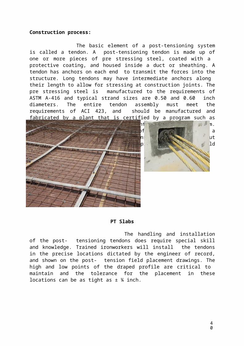
Construction process:
The basic element of a post-tensioning system is called a tendon. A post-tensioning tendon is made up of one or more pieces of pre stressing steel, coated with a protective coating, and housed inside a duct or sheathing. A tendon has anchors on each end to transmit the forces into the structure. Long tendons may have intermediate anchors along their length to allow for stressing at construction joints. The pre stressing steel is manufactured to the requirements of ASTM A-416 and typical strand sizes are 0.50 and 0.60 inch diameters. The entire tendon assembly must meet the requirements of ACI 423, and should be manufactured and fabricated by a plant that is certified by a program such as the Post-Tensioning Institute's Plant Certification Program. To get an idea of the high strength of this type of steel, a typical steel strand used for post-tensioning will yield about 243,000 psi. In contrast, a typical piece of rebar will yield about 60,000 psi.
PT Slabs
The handling and installation of the post- tensioning tendons does require special skill and knowledge. Trained ironworkers will install the tendons in the precise locations dictated by the engineer of record, and shown on the post- tension field placement drawings. The high and low points of the draped profile are critical to maintain and the tolerance for the placement in these locations can be as tight as ± ¼ inch.
40

A typical draped profile in an elevated concrete slab would route the post-tensioned reinforcement through a high point over the slab's supports, and through a low point in
between those supports.
Other trades working on the deck prior to concrete placement must be aware that they cannot disturb or move the tendons to accommodate their work. In elevated slab construction, the tendons typically are grouped in bundles in order to increase the spacing between tendons and improve the constructability of the slab.
Bulb End or Dead End
After the concrete is placed, it must achieve proper strength before the tendons are tensioned. This is typically 75% of the concrete's 28-day design strength, and is specified in the project documents. The tensioning of the tendons, also known as the stressing operation, is achieved by using a hydraulic jack. At least one end of each tendon will have been installed with a length of pre stressing steel protruding through the edge form and beyond the edge of the slab; this is known as the
38

stressing tail. A plastic pocket former also will have been installed at this location to create a stressing pocket.
A plastic pocket former installed at this location creates a stressing pocket.
When the edge form and pocket former are removed, the strand tail and stressing pocket are exposed to allow the ironworker to use the stressing jack to apply the force in the tendon.
Live End
The forces generated when the tendons are stressed are high enough to damage the structure or even cause injury to people working on the job if the installation and stressing are not done properly. Individuals performing the
39

40
installation and stressing of the post-tensioning system should be certified by an independent third-party certification program such as the Post Tensioning Ironworker CertificationProgram to ensure the person has received the proper training and demonstrated the knowledge needed to properly perform the work.
c. slabs:
A structure refers to a system of connected parts used to support forces (loads). Buildings, bridges and towers are examples for structures in civil engineering. In buildings, structure consists of walls floors, roofs and foundation. In bridges, the structure consists of deck, supporting systems and foundations. In towers the structure consists of vertical, horizontal and diagonal members along with foundation. A structure can be broadly classified as
(i) sub structure and (ii) super structure.
The portion of building below ground level is known as sub-structure and portion above the ground is called as super structure. Foundation is sub structure and plinth, walls, columns, floor slabs with or without beams, stairs, roof slabs with or without beams etc is super structure. Many naturally occurring substances, such as clay, sand, wood, rocks natural fibers are used to construct buildings. Apart from this many manmade products are in use for building construction. Bricks, tiles, cement concrete, concrete blocks, plastic, steel & glass etc are manmade building materials. Cement concrete is a composites building material made from combination of aggregates (coarse and fine) and a binder such as cement.
The most common form of concrete consists of mineral aggregate (gravel & sand), Portland cement and water. After mixing, the cement hydrates and eventually hardens into a stone like material. Recently a large number of additives known as concrete additives are also added to enhance the quality of concrete. Plasticizers, super plasticizers, accelerators, retarders, pazolonic materials, air entertaining agents, fibers, polymers and silica furies are the additives used in concrete. Hardened concrete has high compressive strength and low tensile strength. Concrete is generally strengthened using steel bars or rods known as rebars in tension zone. Such elements are “reinforced concrete” concrete can be moulded to any complex shape using suitable form work and it has high durability, better appearance, fire resistance and economical. For a strong, ductile and durable construction the reinforcement shall have high strength, high tensile strain and good bond to concrete and thermal compatibility. Building components like slab walls, beams, columns foundation & frames are constructed with reinforced concrete. Reinforced concreted can be in-situ concreted or precast concrete.
For understanding behaviour of reinforced concrete, we shall consider a plain concrete beam subjected to external load

41
SHEAR WALLS :
Shear walls are vertical elements of the horizontal force resisting system.
The figure shows a typical shear wall. Shear walls are typically wood frame stud walls covered with a structural
sheathing material like plywood. Shear walls have four parts:
Framing members Sheathing Nails Hold-downs
The length of a shear wall is determined by the location of the hold-downs
When the sheathing is properly fastened to the stud wall framing, the shear wall can resist forces directed along the length of the wall. When designed and constructed properly, shear walls will have the strength and stiffness to resist the horizontal forces.
Shear walls should be located on each level of the structure including the crawl space.
Shear walls should create a box structure
Note shear walls in each corner and in-between corners, with stucco in between
To be effective, shear walls should be equal length and placed symmetrically on all four exterior walls of the building.
Note how shear walls are evenly distributed
As long as the dimensions of the box are 3:1, you only need to worry about the outside walls
Egs.: a 25-foot wide building with conventional diagonal sheathing will not require interior shear walls until its length exceeds 75 feet unless the strength or stiffness of the exterior shear walls are inadequate.
Shear walls should be added to the building interior:
when exterior walls cannot provide sufficient strength and stiffness or when the allowable span-width ratio for the floor or roof diaphragm is
exceeded
It is important that shear walls align vertically
Shear walls are most efficient when they align vertically and are supported on foundation walls or footings.

42
When shear walls do not align, other parts of the building will need additional strengthening.
Example: Consider an interior wall supported by a subfloor over a crawl space with no continuous footing beneath the wall. To be used as shear wall, the subfloor and its connections will have to be strengthened near the wall.
For new construction:
thicker plywood or extra nailing and connections can be added.
Retrofit work: Existing floor construction is not easily changed.
most retrofit work uses walls with continuous footings underneath them as shear walls.
Another type of alignment problem occurs when the ends of shear walls do not align from story to story.
Creates need for extra framing members and connections in the walls for hold- down devices.
Hold-down devices must transfer the uplift from the shear wall to framing members that can resist it.
Another alignment problem occurs when full height studs are not available
Special connections must be added. These connections must assemble enough of the structure’s framing to resist
the uplift.
The figure shows a second story shear wall that is vertically offset from the shear wall of the first story – the top floor shear wall is wider than the bottom floor wall.
Since they don’t align, special connections will be needed, such as shown on the below fig.

Shear walls resist two types of forces: shear forces and uplift forces.
Horizontal forces are transferred from the ground to the structure above it by the connections to the shear wall.
The strength of the lumber, sheathing and fasteners must resist these shear forces or the wall will tear or “shear” apart as shown in the figure.
Discussion of figure
Point out shear in plywood. Note that the shear occurs in line with the window opening. This is very
common, as it represents a weak area. Use a piece of paper to demonstrate shearing from horizontal forces
Uplift forces try to lift up one end of the wall and push the other end down. In some cases, the uplift force is large enough to tip the wall over. Uplift forces are greater on tall short walls and less on low long walls. Bearing walls have less uplift than non-bearing walls because gravity loads on shear
walls help them resist uplift. When gravity loads cannot resist all of the uplift, shear walls need hold-down devices
at each end. The hold-down device then provides the necessary uplift resistance.
43
44
Shear Walls
WHAT ARE THE FUNCTIONS OF A SHEAR WALL?
What are the two functions of a shear wall?
Strength and Stiffness
The figure shows strength and stiffness
Strength
Shear walls must provide the necessary lateral strength to resist horizontal earthquake forces.
When shear walls are strong enough, they will transfer these horizontalforces to the next element in the load path below them, such as other shear walls, floors, foundation walls, slabs or footings.
Stiffness
Shear walls also provide lateral stiffness to prevent the roof or floor above from excessive side-sway.
When shear walls are stiff enough, they will prevent floor and roof framing members from moving off their supports.
Also, buildings that are sufficiently stiff will usually suffer less

45
FORMWORK:
Form work is the term used for temporary timber, plywood, metal or other material used to provide support to wet concrete mix till it gets strength for selfsupport. It provides supports to horizontal, vertical and inclined surfaces or also provides support to cast concrete according to required shape and size. The form work also produces desired finish concrete surface.
Shuttering or form work should be strong enough to support the weight of wet concrete mix and the pressure for placing and compacting concrete inside or on the top of form work/shuttering. It should be rigid to prevent any deflection in surface after laying cement concrete and be also sufficient tight to prevent loss of water and mortar form cement concrete. Shuttering should be easy in handling, erection at site and easy to remove when cement concrete is sufficient hard.
MIVAN and MAINI Technology:
The system of aluminium form of those technology formwork has been used widely in the construction of residential units and mass housing projects. It is fast, simple, adaptable and cost effective. It produces total quality work which requires minimum maintenance and when durability is the prime consideration. This system is most suitable for Indian condition as a tailor-made aluminium formwork for cast-in-situ fully concrete structure.
Mivan is an aluminium formwork system developed by a European construction company, Where Maini is developed by Indian company. In 1990, the Mivan Company Ltd. from Malaysia started manufacturing these formwork systems. Today, more than 30,000sqm of formwork from Mivan Co. Ltd. is used across the world. There are a number of buildings in Mumbai that are being constructed with the help of the Mivan system, that has proven economical as well as satisfactory for the overall Indian construction environment. One of the architectural examples is XRBIA which uses Mivan system to achieve its dream of “A house for every Indian”.
The technology has been used extensively in Europe, Gulf countries, Asia and other parts of the world. Mivan technology is suitable for constructing large number of houses in a short span of time using room size forms to construct walls and slabs in one continuous pour on concrete. In this system of formwork construction, cast-in-situ concrete wall and floor slabs cast monolithic provides the structural system in one continuous pour. To facilitate fast construction, early removal of forms can be achieved by hot air curing/ curing compounds. Large room sized forms for walls and floor slabs are erected at site. These strong and sturdy forms are fabricated with accuracy and are easy to handle. The concrete is produced in RMC batching plants under strict quality control and convey it to site with transit mixers.
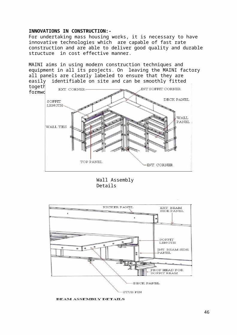
INNOVATIONS IN CONSTRUCTION:-For undertaking mass housing works, it is necessary to have innovative technologies which are capable of fast rate construction and are able to deliver good quality and durable structure in cost effective manner.
MAINI aims in using modern construction techniques and equipment in all its projects. On leaving the MAINI factory all panels are clearly labeled to ensure that they are easily identifiable on site and can be smoothly fitted together using the formwork modulation drawings. All formwork begins at a corner and proceeds from there.
Wall Assembly Details
46

SIMPLICITY – PIN AND WEDGE SYSTEM
The panels are held in position by a simple pin and wedge system that passes through holes in the outside rib of each panel. The panels fit precisely, simply and securely and require no bracing. Buildings can be constructed quickly and easily by unskilled labour with hammer being the only tool required. Once the panels have been numbered, measuring is not necessary. As the erection process is manually, tower cranes are not required. The result is a typical 4 to 5 day cycle for floor – to – floor construction.
EFFICIENT – QUICK STRIP PROP HEAD:
One of the principal technical features which enables this aped to be attained using a single set of formwork panel is the unique V shaped a prop head which allows the ‘quick strip’ to take place whilst leaving the propping undisturbed.
The deck panels can therefore be resumed immediately.
50
Uses of Maini Formwork:
3S – System of Construction – Speed, Strength, Safety Column and beam construction are eliminated Walls and slabs are cast in one operation Specially designed, easy to handle light weight pre-engineered aluminium forms Fitting and erecting the portion of shuttering Carrying out concreting of the walls and slabs together

48
ADVANTAGES:
Maini formwork requires relatively less labour More seismic resistance Increased durability Lesser number of joints and reduced leakages Higher carpet area Smooth finishing of wall and slab Uniform quality of construction Negligible maintenance Faster completion
LIMITATIONS:
Even though there are so many advantages of Maini formwork the limitations cannot be ignored. However the limitations do not pose any serious problems. They are as follows: -
Because of few small sizes finishing lines are seen on the concrete surfaces Services after completing become slightly difficult due to the small width of components It requires uniform planning as well as uniform elevations to be cost effective Due to box-type construction, contraction cracks are likely to appear Heat of hydration is high due to shear walls It is rigid in design once placed, as any alteration becomes tough later Cost equipment is high Cleaning is required for every use.
Remedial Measures:
It is possible to minimize contraction cracks by providing control strips in the structure which could be concreted with a delay of about 3-7 days after major concreting. The problem of cracking can be avoided by minimizing the heat of hydration by using flash.
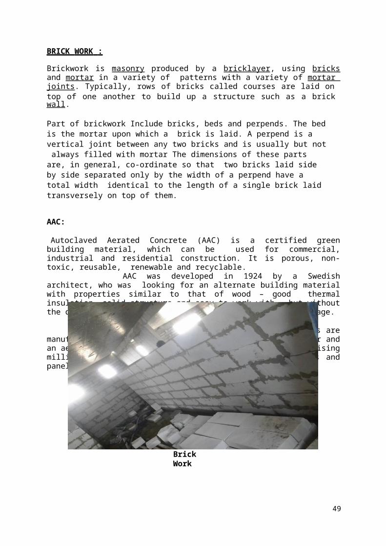
BRICK WORK :
Brickwork is masonry produced by a bricklayer, using bricks and mortar in a variety of patterns with a variety of mortar joints. Typically, rows of bricks called courses are laid on top of one another to build up a structure such as a brick wall.
Part of brickwork Include bricks, beds and perpends. The bed is the mortar upon which a brick is laid. A perpend is a vertical joint between any two bricks and is usually but not always filled with mortar The dimensions of these parts are, in general, co-ordinate so that two bricks laid side by side separated only by the width of a perpend have a total width identical to the length of a single brick laid transversely on top of them.
AAC:
Autoclaved Aerated Concrete (AAC) is a certified green building material, which can be used for commercial, industrial and residential construction. It is porous, non-toxic, reusable, renewable and recyclable.
AAC was developed in 1924 by a Swedish architect, who was looking for an alternate building material with properties similar to that of wood – good thermal insulation, solid structure and easy to work with – but without the disadvantage of combustibility, decay and termite damage.
Biotech ACE blocks and panels are manufactured using fly ash mixed with cement, lime, water and an aerating agent. The resultant building material, comprising millions of tiny air pores, is set and cut into blocks and panels of varying sizes.
Brick Work
49
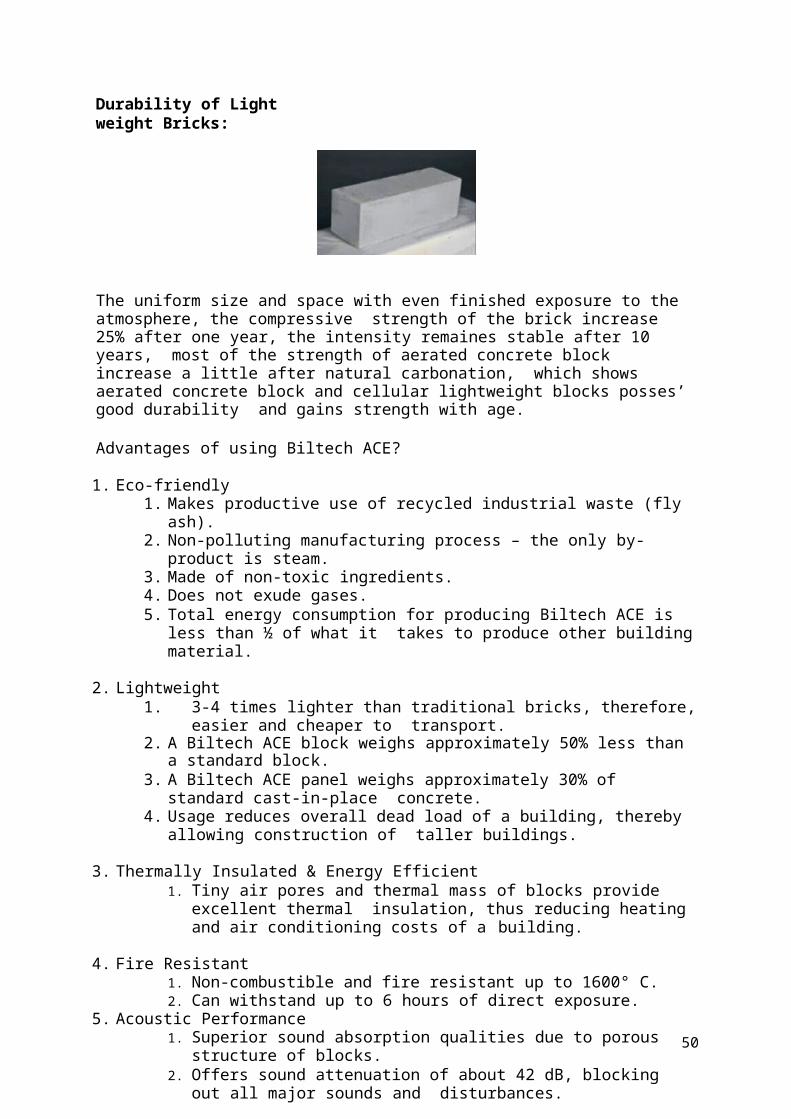
Durability of Light weight Bricks:
The uniform size and space with even finished exposure to the atmosphere, the compressive strength of the brick increase 25% after one year, the intensity remaines stable after 10 years, most of the strength of aerated concrete block increase a little after natural carbonation, which shows aerated concrete block and cellular lightweight blocks posses’ good durability and gains strength with age.
Advantages of using Biltech ACE?
1. Eco-friendly1. Makes productive use of recycled industrial waste (fly ash).2. Non-polluting manufacturing process – the only by-product is steam.3. Made of non-toxic ingredients.4. Does not exude gases.5. Total energy consumption for producing Biltech ACE is less than ½ of what it
takes to produce other building material.
2. Lightweight1. 3-4 times lighter than traditional bricks, therefore, easier and cheaper to
transport.2. A Biltech ACE block weighs approximately 50% less than a standard block.3. A Biltech ACE panel weighs approximately 30% of standard cast-in-place
concrete.4. Usage reduces overall dead load of a building, thereby allowing construction of
taller buildings.
3. Thermally Insulated & Energy Efficient1. Tiny air pores and thermal mass of blocks provide excellent thermal
insulation, thus reducing heating and air conditioning costs of a building.
4. Fire Resistant1. Non-combustible and fire resistant up to 1600° C.2. Can withstand up to 6 hours of direct exposure.
5. Acoustic Performance1. Superior sound absorption qualities due to porous structure of blocks.2. Offers sound attenuation of about 42 dB, blocking out all major sounds and
disturbances.
50

51
3. Ideal for schools, hospitals, hotels, offices, multi-family housing and other structures that require acoustic insulation.
6. Easy Workability and Design Flexibility1. Blocks can be easily cut, drilled, nailed, milled and grooved to fit individual
requirements.2. Available in custom sizes.3. Simplifies hydro-sanitary and electrical installations, such as pipes or ducts,
which can be installed after the main construction is complete.7. Sustainable
1. Retains properties over time.2. Made of non-allergenic material.3. Use of Biltech ACE improves indoor air quality.
8. Earthquake Resistant1. Lightweight blocks reduce mass of a structure, thus decreasing the impact of
an earthquake on a building.2. Non-combustible nature provides an advantage against fires, which commonly
accompany earthquakes.9. Precision
1. Available in exact sizes.2. Results in smooth walls with perfect contact between different elements.3. Reduces cement and steel usage.
10. Termite/Pest Resistant1. Due to structure of blocks, Biltech ACE cannot be damaged or infested by
termites and other pests.11. Cost Effective
1. Reduces operating cost by 30% to 40%.2. Reduces overall construction cost by 2.5% as it requires less jointing and
reduces need for cement and steel.3. High-insulation blocks save up to 30% in energy costs.4. Variety in sizes of blocks helps increase carpet area.5. Wall painting and plastering last longer as almost nil efflorescence affects
Biltech ACE. This translates into lower maintenance costs.12. Faster Construction
1. Reduces construction time by 20%.2. Different sizes of blocks help reduce the number of joints in wall masonry.3. Lighter blocks make construction easier and faster.
Easy to install. Sets and hardens quickly
QUALITY CHECKS FOR AAC: Dimension Plumb Drop test Color test Damages Should be free from oil

60
Black spotsAAC blocks are made with fly ash and admixtures and foam, foam is also called as sludge
(to reduce water absorption). If the form content increases then block will easily breaks.
Polyglaze jointing mortar:It is a thin layer, high strength, pre mixed, quality assured mortar
comprising of ordinary Portland cement specially graded sand and polymers. It is a binding material used to bind AAC blocks.
Procedure: Firstly check the level of the flooring .As per drawing considerations we have to
provide the room dimensions and mark the provisions for the walls, then lay the PCC bed after that lay the AAC blocks as per our requirement we have to choose the type of bond we have to lay. Let us consider English bond where no two bricks will come in same line which reduces the cracks in bricks. As jointing material we use polyglaze jointing mortar. The thickness of the mortar is 3 to 5mm.
Dimensions (AAC): 600*200*200(These are commonly used for external walls they doesn’t require any
extra beds) 600*200*100(These are commonly used for internal walls they required internal
beds). After the completion of laying the walls, check their verticality using the plumb and
by using line dory check the alignment of the walls. There are another method to check the levelingof the walls that is tube level. In brick work we should not lay the total height of the wall in a day. First lay up to the
sill level and then lintel and then beam bottom level. A pin or staggered is provided to continue further brick work.

53
SAFTEY:
HSE (Health Safety Environment)
HSE Performance Measurement
To draw focus and attention to safety.
Safety Performance measurement of organizations & Individuals.
Trend Analysis
To plan proactively based upon the trend.
Statutory Requirement?
Business Tool
HSE Performance Indicators
• Lagging or Downstream Indicators of Safety Performance
• Leading or Upstream Indicators of Safety Performance.
Lagging Indicators
• Provides historical information about safety performance (i.e.; After an incident /
accident happens)
• Useful in identifying the causes behind an accident / incident and implement measures
to prevent recurrences.
Types of lagging Indicators
First Aid (FA):
• A work related minor injury / illness, which can be treated by First Aider or
equivalent and does not require any consultation with professional Physician
(Doctor). Example : Minor cut


15. SITE IMAGES
Rock Crushing Plant

Completed Blocks
RMC Plant at Site

Tower Cranes at Site Suspended Rope Platform
Podiums Construction Shuttering Work

CONCLUSION:
70
Summer Internship at My Home-Vihanga has given me a platform to gainknowledge regarding the constructions that were ongoing on site. Not only the construction work but also works related to the management field i.e. planning. It also helped me to apply the theoretical knowledge in practical methods. It has truly been an eye opener to the practical aspects of construction and I will be taking back an experience which would back me up throughout my career. I amvery thankful to all the officials who helped me by sharing key factors regarding all the work. Throughout my internship I had a chance to experience awonderful working environment where I could gain the best of my knowledge.

71


![BBMA [MHV]](https://img.dokumen.tips/doc/110x75/577c861b1a28abe054bfd7a9/bbma-mhv.jpg)