Embed Size (px)
Citation preview

Disclosure to Promote the Right To Information
Whereas the Parliament of India has set out to provide a practical regime of right to information for citizens to secure access to information under the control of public authorities, in order to promote transparency and accountability in the working of every public authority, and whereas the attached publication of the Bureau of Indian Standards is of particular interest to the public, particularly disadvantaged communities and those engaged in the pursuit of education and knowledge, the attached public safety standard is made available to promote the timely dissemination of this information in an accurate manner to the public.
इंटरनेट मानक
“!ान $ एक न' भारत का +नम-ण”Satyanarayan Gangaram Pitroda
“Invent a New India Using Knowledge”
“प0रा1 को छोड न' 5 तरफ”Jawaharlal Nehru
“Step Out From the Old to the New”
“जान1 का अ+धकार, जी1 का अ+धकार”Mazdoor Kisan Shakti Sangathan
“The Right to Information, The Right to Live”
“!ान एक ऐसा खजाना > जो कभी च0राया नहB जा सकता है”Bhartṛhari—Nītiśatakam
“Knowledge is such a treasure which cannot be stolen”
“Invent a New India Using Knowledge”
है”ह”ह
IS 2164 (1961): Method for calculation of bulk quantitiesof petroleum and liquid petroleum products [PCD 1: Methodsof Measurement and Test for Petroleum, Petroleum Productsand Lubricants]


IS:2164 -1961 (Jleaffirmed 1’996 )
Indian Stacdard METHOD FOR CALCULATION OF BULK
-QUANTITIES OF PETROLEUM AND LIQUID PETROLEUi4 PRODUCTS
( Fourth Reprint OCTOBER 1997 )
UDC 665.5 : 531.732
0 Copyright 1962 r
BUREAU OF INDIAN STANDARDS MANAK BHAVAN, 9 BAHADUR SHAH ZAFAR MARG
NEW DELHI 110002
Gr 7 November 1962
IS : 2164 - 1961
Indian Standard METHOD FOR CALCULATION OF BULK
QUANTITIES OF PETROLEUM AND LIQUID PETROLEUM PRODUCTS
Petroleum M_easurements Sectional Committee, CDC 32
Chairman Representing
DR H. K. JOSHI Ess~BoS;btard Refining Co of India Ltd,
n4embers
SHRI T. B. BHONSLE Central Public Works Department EXECUTIVE ~ENGINEER ( Alternate )
SHRI E. M. BHUMCARA Caltex ( India ) Ltd, Bombay; and Caltex Oil Rrfining ( India) Ltd, Visakhapatnam
SHRI V. H. KHAKHAR Caltex ( India ) Ltd, Bombay ( Alternate )
SHRI N. S. RAO ( Alternate ) Caltex Oil Refining ( India ) Ltd, Visakhapatnam SHRIX. V. BOLE Ministry of Finance ( Revenue Division ) DIRECTOR CSI\u6ndian Institute of Petroleum, Dehra
SHRI K. B. GANESAN Directorate General of Civil Aviation (Ministry of Transport & Communications )
SHRI S. G. GHOSHALKAR Railway Board ( Ministry of Railways ) SHRI S. B. J. RAJAIAH ( Alternate )
SHRI J. M. GIJHA Department of Mines & Fuel ( Ministry~of Mines & Fuel )
SHRI A. S. KRISHNASWAMY Indian Oil Co Ltd, Bombay SHRI V. D. BAPAT ( Alternate )
SHRI S. D. MEHTA Indian Refineries Ltd, New Delhi SHRI S. S. PANDIT ( Altematc )
SHRI N. A. MENDES Indo-Burma Petroleum Co, Bombay SHRI R. M. CHARI ( Alternate )
SHRI S. N. NAKHATE Esso Standard Eastern, Inc, Bombay SHRI A. N. NANDY Ministry of Defence ( R & D )
SHRI D. M. BANERJEE ( Alternate ) SHRI K. SRINIVASA RAO Standing Metric Committee, Ministry of Commerce
& I.ndustry SHRI T. R. RAO Burmah-Shell Oil Storage & Distributing Co of
India Ltd, Bombay SHRI A. S. VAIDYA ( Altemak)
SHRI K. K. ROY SHRI M. C. DE~AI ( Alternate )
Western India Oil Distributing Co Ltd, Bombay
( Continued on pag# 2 )
BUREAU OF INDIAN STANDARDS MANAK BHAVAN, 9 BAHADUR SHAH ZAFAR MARC
NEW DELHI 110002
IS : 2164 - 1961
Members Refiesenting DR B. S. SUBRAHMANYAM Assam Oil Co Ltd, Digboi SXRI H. DSURr Ministry of Finance ( Revenue Division )
SHRI MANOHAR LAL ! Alkmate) $~AJ SWARAN SINCH Directorate of Supply & Transport, Quartermaster
General’s Branch, Army Headquarters CAPT A. K. PANDYA (Alternate)
DR SADGOPAL, Director, BIS ( &-oJfcio Member ) Deputy Director ( Chem )
secretar) SHRI D. DAS GUPTA
Assistant Director (~Chem ),BIS
Gauging of Tanks and Calculation of Bulk Quantities of Oils in Tanks ( Other Than Pressure Vessels ) Subcommittee, CDC 32 : 3
Sinu T. W. RAO
Members
Burmah-Shell Oil Storage & Distributing Co of India&d, Bombay
SH~U A. S. VAHWA ( Alternate to Shri T. R. Rao )
SHRI A. S. KRISHNUWAMY SHRI V. D. BAPAT ( Alternak )
Indian Oil Co Ltd, Bombay
SHRI S. N. NAKHATE DR B. S. SUBRAHMANYAM
Esso Standard Eastern., Inc, Bombay
SHRI H. D. Sum Assam Oil Co Ltd, Digboi
SHRI MANOHAR LAL ( Alternate ) Ministry of Finance ( Revenue Division )
LS : 2164 - 1961
Indian Standard METHOD FOR CALCULATION OF BULK
QUANTITIES OF PETROLEUM AND LIQUID PETROLEUM PRODUCTS
0. FOREWORri
0.1 This Indian Standard was adopted by the Indian Standards Institu- tion on 20 June 1961, after the draft finalized by the Petroleum Measure- ments Sectional Committee had been approved by the Chemical Division Council.
0.2 The Indian Standards on tank calibration, gauging, sampling, temperature measurement and determination of density have laid down procedures which, when followed, allow the volume, temperature and density of a bulk quantity of oil to be determined with considerable precision. The care with which these physical measurements have been made will be largely nullified if the subsequent calculations are carried out inaccurately or incorrectly. The quantity calculated will be substantially correct if:
a) The accepted* volume is substantially correct. This implies that: 1) the container has been accurately calibrated and its Calibra-
tion Table correctly computed by recognized methods. For vertical and horizontal tanks, the recommendations laid down in the following standards shall apply:
IS:2007-1961 METHOD FOR CALIBRATION OF VERTICAL OIL STORAGE TANKS
IS:2008-1961 METHOD FOR COMPUTATION OF CAPACITY TABLES FOR VERTICAL OIL~~ORAGE TANKS
IS:2009-1961 METHOD FOR CALIDRATION OF ;IORIZONTAL ANDTILTED OIL STORAGE TANKS
IS : 2166-1963 METHOD FOR COWUTATI~N OF GYFVZITY TARLES FOR HORIZONTAL AND TILTED OIL STORAGE’~ANKS
2) the oil depth has been correctly measured and recorded by the methods laid down in IS : 1518-1960 Method for Gauging of Petroleum and Liquid Petroleum Products;
b) The container has been correctly sampled in accordance with IS: 1447-1966 Methods of Sampling of Petroleum and Its Products;
* ‘ Accepted ’ means the ’ figure taken into further calculation ‘.
3
I!3:2164-1961
c) The accepted oil temperature is substantially correct and has been obtained in accordance with the recommendations laid down in IS : 15 19 ( Part I )-1961 Method for Temperature Measurement of Petroleum and Its Products, Part I; and
d) All densities have been determined in accordance with the method for determination of density laid down in P: 16 of IS : 1448 ( Part I )-I960 Methods of Test for Petroleum and Its Products, Part I.
0.3 The methods of calculation given in this standard have, therefore, been drawn up to give the maximum possible accuracy m the final calculated quantities compatible with the precision of the physical measurements.
0.3.1 For large quantities, namely, supplies made by tanker, pipeline, transfer from a shore tank into a ship, barges, etc, it is essential that the methods specified in this standard shall be used for accurate assessment. IHowever, for small quantities, namely, supplies made in barrels, tank lorries and rail tank wagons of which a very large number of despatches are made daily, a short method has been given in Appendix A. This simpler method would save time in calculation and would be sufficiently accurate for purposes of billing.
0.4 Wherever a reference to any Indian Standard appears in this standard, it shall be taken as a reference to the latest version of the standard.
0.5 In reporting the result of a calculation made in accordance with this standard, if the final value, observed or calculated, is to be rounded off, it shall be done in accordance with IS : 2-1960 Rules for Rounding Off Numerical Values ( Revised ).
1. SCOPE
1.1 This standard prescribes method of calculations, normal and special, of bulk quantities of petroleum and liquid petroleum products.
1.1.1 The normal method shall apply to all liquid petroleum products in bulk except those listed in 1.1.2.
1.1.2 The special method of calculations, which is a modification of the normal method of calculations, will usuall;r be necessary if the product concerned is:
a) a liquid under high pressure ( propane, butane, etc );
b) a volatile liquid in vapour-tight storage;
4
IS : 2164 - 1961
c) a liquid contained in a pipeline;
d) a liquid stored in a tank subject to bottom movement; or
e) a liquid stored in a floating roof tank.
2. TERMINOLOGY
2.1 For the purpose of this standard, the following definitions shall apply:
Accepted Temperature - Is the temperature reading which is taken into further calculation, the temperature being measured as prescribed in IS : 1519 (Part I)-1961 Method for Temperature Measurement of Petroleum and Its Products, Part I. However, if the initial and final temperatures of the oil before and after the movement of foil are different, the accepted temferature shall be the weighted average of these two temperatures, the weights being based on the estimated volumes of oil before and after its movement.
Algebraic Sum - Of a number of quantities is their sum, having due regard to the signs of these quantities. For example, if any containers A, B and C are receiving oil and, at the same time, the container C is making a transfer. And if the con?:ainers A, B and C have received a quantity X, Y and /z, respectively, ~of oil and at the same time container C has delivered a quantity X1, then the net change in the quantity of oil in the containers is X + 2” + S -X,.
Gross Measured Volume - Is the total volume of material in a container for a given dip or gauge and at the observed tempera- * ture at the time of gauging.
Net Measured Volume - Is the gross measured volume at the accepted temperature after deducting any free water and sediment which may be present.
Net Quantity Received or Delivered - Is the difference between the net volume or net weight of clean oil, before and after the oil movement for each container under consideration.
Net Volume cf Glean Oil at the Accepted Temperature - Is the net measured volume of oil at the accepted temperature, less the quantity of any water and sediment in suspension in the oil.
Net Volume of Clean Oil at Standard Reference Tempera- tare - Is the net measured volume of oil, reduced to standard reference temperature of 15°C by means of the appropriate ASTM/IP Volume Reduction Table, less the quantity of any water and sediment in suspension in the oil. *
5

IS : 2164 - 1961
Standard Reference Temperature - 15%.
Weight of Net Clean Oil- Is the weight in air -of the net volume of clean oil at standard reference temperature.
SECTION I METHODS FOR NORMAL CALCULATIONS
3. GENERAI.
3.1 The final quantity of oil may be required in terms of weight in air, volume at standard reference temperature, or for some purposes, volume at the accepted temperature. All these requirements involve a know- ledge of the volume of oil in a container.
3.2 When several containers are involved, the quantity of oil in each container shall be separately calculated and the final quantity shall be recorded by adding the separate quantities so obtained by following the procedures laid down in this standard. For the purpose of measurement, a pipeline is considered as a separate container and all appropriate pipe- lines shall, therefore, be taken into consideration. Pipelines do not lend themselves to simple methods of measurements and are most conveniently dealt with either completely empty or completely full, although with full pipelines some correction for difference in temperature before and after an oil movement, may be necessary. Section II.
Pipelines are dealt with separately in
4. INTERPRETATION OF REPORTED MEASUREMENTS
4.1 Measurements Reported - Gauging reports shall give all relevant details of tank number or numbers, the position and number of dip hatches, product, date and time, etc. contain the following information:
The gauger’s note shall, in addition,
a)
b)
Dip or Ullage ( With Height of Refereke Point Above th Datum Point ) -The dip or ullage shall be taken as prescribed in IS : 1518-1960 Method for Gauging of Petroleum and Liquid Petroleum Products, from the dip hatch specified on the tank calibration table, except as described in 10.2.
Temperature - It shall be middle or the average of upper, middle and lower temperatures asprescribed in IS : 1519 ( Part I )-1961 Method for Temperature Measurement of Petroleum and Its Products, Part I. In exceptional cases, namely, heated oils, temperature of samples drawn from other levels and from more than one dip hatch may be reported.
c) Water Dips - Water dips shall be taken as prescribed in IS : 151% 1960 Method for Gauging of Petroleum and Liquid
6

Isr2164-1961
Petroleum Products, from the dip hatch specified in the tank calibration table but where incomplete water bottoms are encoun- tered, dips will be reported from more than one dip hatch if the tank is so fitted.
d) Sludge - If sludge is present at the bottom of the tank the gauger may report this by an ullage measurement or by a measurement in accordance with appropriate Indian Standard when published.
4.2 In addition to the above, the following information will be required:
a) Density of the contents of each container, and
b) Percentage of water or sediment in suspension in the product.
4.3 Preliminary Calculations - Before the finai calculations of oil quantities can be commenced, it may be necessary to adjust the reported measurements in order to obtain correct ( ‘ true ’ ) figures, namely, the determination of true dip or ullage.
4.3.1 Determination of True Dip or Ullage -The true dip or ullage is that taken from the dip hatch specified on the tank calibration table and will be the dip or ullage normally reported. Exceptions to this are:
a) when tank bottom movement is suspected. The method of calculating oil volume in these circumstances is treated separately in lO.2.
b) where the dip or ullage reported from the dip hatch specified on the tank calibration table shows that the oil level is below the levelof the first entry in the tank calibration table the volume of oil shall be determined as specified in 10.1.
4.3.2 Determination af Average Dip - The average dip, where required, shall be determined by the following procedure:
a) If the tank is fitted with a central dip hatch and a number of peripheral dip hatches, first compute the arithmetic means of the dips at the central dip hatch and at each peripheral dip hatch taken in pairs. The average dip for the tank is then the sum of these arithmetic means divided by the number of arithmetic means so computed.
b) If the tank is fitted with a central dip hatch, n peripheral dip hatches and n intermediate hatches situated midway between the centre and the periphery of the tank, the average dip is
n x central dip + the sum of all the non-central dips ).
7
IS : 2164 - 1961
c) If the tank is fitted with the peripheral dip hatches only, the average dip of the tank is the arithmetic mean of the dips at ail dip hatches.
Ed) In all other cases make the best possible estimate of the average dip of the tank from the dips at all dip hatches, making due allowance for the relative positions of the dip hatches.
4.3.3 Determination of True Water D$I - The true water dip is that taken from the dip hatch specified on tank calibration table, and will be the water dip normally reported. Exceptions to this are:
a) when tank bottom movement is suspected. The method of calculating water volumes in these circumstances is treated separately in 10.2, and
b) where the water dip reported shows that the water level is below the level of the first entry in the tank calibration table, the volume of water shall be determined as specified in 10.1.
4.3.4 Determination of the True Quant$y of Sludge or Sediment at the Bottom of a Tank - When the level of sludge or sediment at the bottom of a tank has been determined by ullage measured at the dip hatch specified on the tank calibration table, the level so reported will normally be the levrl at which the tank calibration table will be entered to obtain the true quantity of sludge or sediment at the bottom of the tank.
If, however, the level so reported is below the level of the first entry in the tank calibration table, then the levels of sludge or sediment shall be measured from all the dip hatches fitted to the tank and an average of these levels obtained by the procedure specified in,4.3.2. The volume of sludge or sediment represented by this average shall be determin- ed as specified in 10.1.
4.3.5 Determination of Accepted Temperature - The accepted temperature of the foil in a tank shall be the middle temperature of the oil in the tank or average of the upper, case may be.
middle and lower temperatures, as the
4.3.6 Determination of Accepted Density - The accepted density of the oil in a tank shall be the density determined on a composite sample prepared in accordance with IS : 1447-1966 Method& of Sampling of Petroleum and Its Products.
4.3.7 Determination of True Percentage of Water and Sediment in Suspen- sion - Where percentages of water and sediment in suspension have been reported on more than one sample, the true percentage of water and sediment in suspension shall be determined by calculating the average percentage, due allowance being given to the approximate quantity of oil represented by each sample on which the percentage has been determined.
8

Is:2164-1961
5. CALCULATION OF VOLUME AT THE ACCEPTED TEMPERATURE
5.1 Gross Measured Volume Before Movement
5.1.1 Obtain from the calibration table for the tank the volume corres- ponding to the true dip ( see 4.3.1) interpolating or using the proportional parts table where this is available, if necessary.
5.1.2 Where ullages are given and the calibration table for the tank has been compiled on an oil depth basis, first convert the ullage to equivalent dip by deducting the ullage from the known distance between the ullage reference point and the dipping datum point.
5.1.3 Where ullages are given and if the tank calibration table is compiled on the ullage basis, proceed as in 5.1.1.
5.2 Volume of Water, Sludge and Se+nent
5.2.1 Obtain from the calibration table for the tank, the volume of free water and sediment corresponding to the true water dip before the oil movement, interpolating or using the proportional parts table where this is available, if necessary.
5.2.2 Where water and/or sediment measurements are given as ullages and the tank calibration table has been compiled on an oil depth basis, convert the ullages to equivalent dips as in 5.1.2 before entering the tank calibration table.
5.2.3 Where the tank calibration table is entered against ullage, convert the true water dip to equivalent ullage by procedure Implied in 5.1.2.
5.2.4 Where water and/or sediment are given as ullages and the tank calibration table has been compiled on an ullage basis, proceed as in 5.1.1.
5.3 Net Measured Volume Before Movement-To obtain the net measured volume of oil in a tank before movement, deduct from the gross measured volume before movement as measured in 5.1, the volume of free water, sludge and sediment before movement as in 5.2.
5.4 Net Volume of Clean Oil at Accepted Temperature Before Movement
5.4.1 To obtain the net volume of clean oil at accepted temperature in a tank before movement, deduct from the net measured volume before movement obtained as in 5.3 the true water and sediment in suspension present in the oil.
5.4.2 Where contracts make an allowance for suspended water and sediment, deduct from the net measured volume before movement the
9
IS : 2164 - 1961
difference between the true and the allowable quantity, of suspended water and sediment.
5.5 Gross Measured Volume After Movement - Use procedure similar. to that prescribed in 5.1.
5.6 Volume of Water, Sludge and Sediment After Movement - Use procedure similar to that described in 5.2.
5.7 Net Measured Volume After Movement - Use procedure similar to that described in 5.3.
5.8 Net Volume of Clean Oil at the Accepted Temperature After Movement -Use procedure similar to that described in 5.4.
5.9 Net Volume -of Clean Oil at Accepted Temperature, Received or Delivered -To obtain the net volume of clean oil at accepted tem- perature, received or delivered as a result of an oil movement, proceed as follows:
a)
b)
Calculate the net volume of clean oil at accepted temperature before and after movement as described in 5.1 to 5.8 in respect of each oil container concerned in the oil movement. For each oil container concerned in the oil movement, determine the difference between the volume in the container before the oil movement and the volume in the container after the oil movement.
c) When more than one container is involved in the oil movement, determine for all containers the algebraic sum of the quantities determined as in (b).
6. CALCULATION OF VOLUME AT STANDARD REFERENCE TEMPERATURE
6.1 Net Volume of Clean Oil at Standard Reference Temperature, Received or Delivered
6.1.1 Deduct from the volume obtained as in 5.9, the true water and sediment in suspension in the oil ( see 4.3.7 ).
6.1.2 Calculate the net volume of oil at 15°C in a tank by multiplying the net measured volume of oil at accepted temperature obtained as in 6.1.1, by the volume correction factor which corresponds to the -accepted temperature and accepted density at 15°C (see 4.3.5 and 4.3.6 ). Obtain this factor from ASTMjIP Table No. 54.
6.13 Where contracts make an allowance for suspended water and sediment, deduct from the volume obtained as in 6.1.1, the difference between the true and, allowable quantity of suspended water -and sediment.
10
IS : 2164 - i961
6.2 Net Volume of Clean Oil at Standard Reference Temperature After Movement - Use procedure similar to that described in 6.1.
6.3 Net Volume of Clean Oil at Standard Reference Temperature, Received or Delivered - To obtain the net volume of clean oil at stan- dard reference temperature received or delivered as a result of an oil movement, proceed as follows:
a) Calculate the net volumes of clean oil at standard reference tem- perature before and after movement for each container concerned in the oil movement.
b) For each oil container concerned in the oil movement, determine the difference between the volume in the~container before the oil movement and the volume in the container after the oil movement.
c) When more than one container-is involved in the oil movement, determine for all containers the algebraic sum of the quantities determined as in (b).
7. CALCULATION OF VOLUME AT ACCEPTED TEMPERATURE (CASES OF TEMPERATURE D IFFERING BEFORE AND AFTER MOVEMENT )
7.1 Calculate as foll0WS: a) Calculate the net volume of clean oil at standard reference
temperature before movement as in 6. From this, calculate the net volume of the clean oil at the accepted temperature by the appropriate factor corresponding to that temperature as obtained from ASTM/IP Table No. 54.
b) CalcuIate the net volume of clean oil after movement at accepted temperature as in (a).
c) Determine the difference in quantities as obtained under (a) and (b). This will give the net quantity of clean oil received or delivered at the accepted temperature.
7.2 ?‘o obtain the net total volume of the oil received or delivered from all the containers, take algebraic sum of the net oil received or delivered as the case may be for each container by the procedures as explained in 7.1.
8. CALCULATION OF WEIGHT
8.1 Oils Containing no Suspaded Water and Sediment
8.1.1 Weight of Clean Oil Before or After Movement - To obtain the weight of clean oil in a tank before or after movement, multiply the net volume of clean oil at standard reference temperature by the appropriate factor
11

!F ‘ving weight per unit volume (see ASTM/IP Petroleum Measurement ables ) .
8.2 Oil Containing Suspended Water and Sediment - Calculate the volume of wet oil at standard temperature, then multiply this volume by the factor giving weight per unit volume ( see ASTM/IP Petroleum Measurement Tables ) corresponding to the wet oil density at standard reference temperature. Calculate the true volume at standard reference temperature of suspended water and sediment in the tank. Assuming the suspended water and sediment to have a density at 15°C of l-000 kg/l, calculate, using the appropriate ASTM/IP weight per unit volume factor, the weight of suspended water and sediment represented by the above determined volume at standard reference temperature. Deduct this weight of suspended water and sediment from the weight of wet oil.
8.3 Weight of Clean Oil Received or Delivered -A To obtain the weight of clean oil received or delivered as a result of an oil movement, proceed as follows:
a) Calculate the weight of clean oil before the oil movement and after the oil movement for each container concerned in the oil movement. Then by difference between these two weights of clean oil, obtain the quantity of oil received or delivered for each container involved in oil movement.
b). Determine the algebraic sum of the quantities as obtained in (a), for all the containers concerned.
9. EXAMf’LES OF NORMAL CALCULATIONS
9.1 The following are some of the examples.
9.1.1 Delivsred Volume at the Observed Temgerature Where Before Delivery and After Delivery Temperatures are Same - The following data and calculations illustrate the recommended procedure for determining the volume of gasoline at observed temperature delivered from a storage tank:
a) Gauging Datu Before Loading Ajkr Loading True gross dip 9.206 m 3.112 m True water dip OdO70 m CO70 m True average 26°C 26°C
temperature
b) Laboratory Data Average density
at tank tern; “‘~7l&ll 0’$7&k&l
perature Density at 15°C ~0.716 3 kg/l O-716 3 kg/l
(ASTM/IP Table No. 53)
12
ISt 2164 - 1961
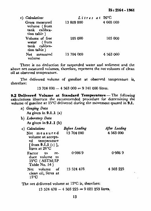
c)- Calculations Gross measured
volume ( from tank calibra- tion table )
Volume of free water tank ci&r _ tion table )
Net measured volume
Lit r es at 26°C 13 809 000 4 668 000
105 000 105 000
13 704 000 4 563 000
There is no deduction for suspended water and sediment and the above net measured volumes, therefore, represent the net volumes of clean oil at observed temperature.
The delivered volume of gasoline at observed temperature is, therefore:
13 704 000 - 4 563 000 = 9 141 000 lines.
92 Delivered Volume at Standard Temperature -The following calculations illustrate the recommended procedure for determining the volume of gasoline at 15°C delivered during the movement quoted in 9.1.
a) Gauging Data As given in 9.1 .l (a)
b) Laboratory Data As given in 9.1 .l (b)
c) Calculations Net measured
volume at accept- led temperature [from 9.1.1 (c) 1, litres at 26°C
Factor to re- duce volume to 15°C ( ASTM/IP Table No. 54 )
Net volume of clean oil, litres at 15°C
Before Loading A* Loading 13 704 000 4 563 000
0.986~9 O-986 9
13 524 478 4 503 225
The net delivered volume at 15% is, therefore:
13 524 478 - 4 503 225 = 9 021 253 IitreS.
13
I8 : 2164 - 1961
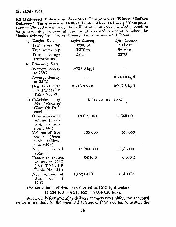
9.3 Delivered Volume at Accepted Temperature Where 6 Before Delivery ’ Temperature Differs from ‘ After Delivery ’ Tempera- ture - The following calculations illustrate the recommended procedure for .dctermining volume of gayoiine at accepted temperature when the ‘ before delivery ’ and ‘ after delivery ’ temperatures are different:
a) Gauging Data True gross dip True water dip True average
temperature
b) Laboratory Data
Average derisit y at 26°C
Azter2aFCdensity
Density at 15°C (ASTM/lP Table No. 53 )
c) Calculation of JVet Volume of Clean Oil Deli- vered
Gross measured volume ( from tank calibra- tion\table )
Volume of free water ( from tank calibra- tion table )
Net measured volume
Factor to reduce volume to 15°C (ASTM/II’ Table No. 54 )
Net volume of clean oil at 15°C
Before Loading
9.206 m 0.070 m 26°C
After Loading
3.112 m 0.070 m 23°C
0.707 9 kg/l -
- O-710 8 kg/l
@716 3 kg/l 0.717 5 kg/l
Li tres at 15%
13 809 000 4 668 000
105 000 105 000
13 704 000 4 563 000
0.986 9 0.990 5
13 524 478 4 519 6’52
The net volume of clean oil delivered at 15°C is, therefore: 13 524 478 - 4 519 652 s 9 004 826 litres.
When the bdfore and after delivery temperatures differ, the accepted temperature shall be the weighted average of these two temperatures, the
14

IS : 2164 - 1961
weightage being based on the estimated volumes of oil before and after its movement.
d) Calculation of Accepted Tmperature Net measured volume before delivery at 26°C = 13 704 000 litres Net measured volume after delivery at 23°C = 4 563 000 litres
Therefore, accepted temperature will be 13 704 000 x 26 + 4 563 000 x 23
18 267 000 = 25.5% ( by rounding off to
‘nearest 0.5% )
and, oil delivered at 25*5”C = 9 004 826 o.g87 5
= 9 118 811 litres. ( Factor O-987 5 obtained from ASTM/IP Table No. 54 )
9.4 Weight Received - The following data and calculations illustrate the recommended procedure for calculating the weight of oil received into an oil storage tank. In this example, it is assumed that the oil was received in accordance with a contract the terms of which allowed -0.20 percent water and sediment in suspension to be considered as ‘ clean oil ‘.
a> Gauging Data True gross dip True water dip True average
temperature Laboratory Data Average density
at tank tem- perature
Average density at 15°C ( from ASTM/IP stable No. 53 )
Suspended water and sediment
Calculations Gross measured
~$m~alib!if:~? table )
Volume of free water ( from tank calibration table )
Before Receipt l-377 m O-066 m 25.5%
Afler Receipt 1 l-709 m 0.922 m 29.5%
b)
C>
0.866 5 kg/l at 25~5°C
0.873 3 kg/l
O-9 percent by volume
At~25.5°C 1 435 938 litres
70 982 litres
0.860 0 kg/l at 29.5%
O-869 4 kg/l
l-3 percent by volume A: 29*5OC
12 574 466 litres
990 126 litres
15
IS : 2164 - 1961
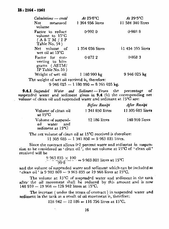
Calculations - contd At 25.5% Net measured 1 364 956 litres
volume Factor to reduce 0.992 0
volume to 15°C (ASTM/IP Table No. 54)
Net volume of 1 354 036 litres wet oil at 15°C
Factor for con- 0.872 2 verting to kilo- grams ( ASTM/ IP Table No. 56 )
Weight of wet oil 1 180990kg
The weight of wet oil received is, therefore:
At 29.5% 11 584 340 litres
0.988 8
11 454 595 litres
0.868 3
9 946 025 kg
9 946 025 - 1 180 990 = 8 765 035 kg.
9.4.1 Suspended Water and Sediment-From the percentage of suspended water and sediment given in 9.4 (b) the corresponding net volume of clean oil and suspended water and sediment at 15°C are:
Volume of clean oil at 15’C
Volume of suspend- ed water and sediment at 15°C
The net volume of clean
Before Receipt After Receipt
1 341 850 litres 11 305 685 1itre.s
12 186 litres 148 910 litres
oil at 15°C received is therefore: 11 305 685- 1 341 850 = 9 963 835 litres.
Since the contract allows 0.2 percent water and sediment in suspen- sion to be considered as ‘ clean oil ‘, the net volume at 15°C of ‘ clean oil ’ received will be
9 963 835 x 100 99.8 = 9 983 803 litres at 15°C
and the volume of suspended water and sediment which can be included as c clean oil ’ is 9 983 803 - 9 963 835 or 19 968 litres at 15°C.
The volume at 15°C of suspended water and sediment in the tank after’ the oil movement shall be reduced by this amount and is now 148910- 19968= 128 942 litres at 15°C.
The increase ( under the terms ofcontract ) in suspended water and sediment in the tank as a result of oil movement is, therefore:
128 942 - 12 186 = 116 756 litres at 15°C.
16
IS : 2164 - 1961
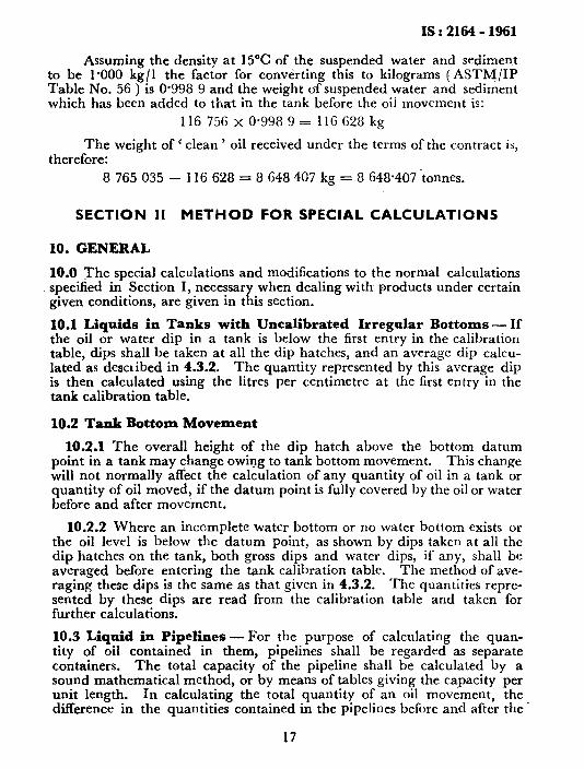
Assuming the density at 15°C of the suspended water and sediment to be 1.000 kg/l the factor for converting this to kilograms (ASTM/IP Table No. 56 ) is O-998 9 and the weight of suspended water and sediment which has been added to that in the tank before the oil movement is:
116 756 x 0.998 9 = I 1G 628 kg
The weight of ‘ clean ’ oil received under the terms of the contract is, therefore:
8 765 035 - 116 628 = 8 648 407 kg = 8 648.407 tonnes.
SECTION II METHOD FOR SPECIAL CALCULATIONS
10. GENERAL
10.0 The special calculations and modifications to the normal calculations specified in Section I, necessary when dealing with products under certain given conditions, are given in this section.
10.1 Liquids in Tanks with Uncalibrated Irregular Bottoms - If the oil or water dip in a tank is below the first entry in the calibration table, dips shall be taken at all the dip hatches, and an average dip calcu- lated as described in 4.3.2. The quantity represented by this average dip is then calculated using the litres per centimetre at the first entry in the tank calibration table.
10.2 Tank Bottom Movement
10.2.1 The overall height of the dip hatch above the bottom datum point in a tank may change owing to tank bottom movement. This change will not normally affect the calculation of any quantity of oil in a tank or quantity of oil moved, if the datum point is fully covered by the oil or water before and after movement.
10.2.2 Where an incomplete water bottom or no water bottom exists or the oil level is below the datum point, as shown by dips taken at all the dip hatches on the tank, both gross dips and water dips, if any, shall be averaged before entering the tank calibration table. The method of ave- raging these dips is the same as that given in 4.3.2. The quantities repre- sented by these dips are read from the calibration table and taken for further calculations.
10.3 Liquid in Pipelines-For the purpose of calculating the quan- tity of oil contained in them, pipelines shall be regarded as separate containers. The total capacity of the pipeline shall be calculated by a sound mathematical method, or by means of tables giving the capacity per unit length. In calculating the total quantity of an oil movement, the difference in the quantities contained in the pipelines before and after the.
17
IS : 2164 - 1961
movement is added to or subtracted from quantities received into or-deli- vered from the tanks, as the case may be. For stock quantity purposes, the quantities contained in the pipelines are added to the relevant stock in the tank or tanks.
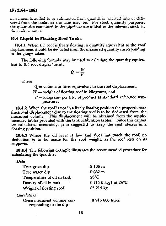
10.4 Liquid in Floating Roof Tanks
10.4.1 When the roof is freely floating, a quantity equivalent to the roof displacement should be deducted from the measured quantity corresponding to the gauge taken.
The following formula may be used to calculate the quantity equiva- lent to the roof displacement:
QPW =- where
Q= volume in litres equivalent to the roof displacement,
W = weight of floating roof in kilograms, and P = kilograms per litre of product at standard reference tem-
perature.
10.4.2 When the roof is not in a freely floating position the proportionate fractional displacement due to the fioating roof is to be deducted from the measured volume. This displacement will be obtained from the supple- mentary tables provided with the tank calibration tables. Sirice this cannot be calculated accurately, jt is suggested to keep the roof always in a floating position.
10.4.3 Where the oil level is low and does not touch the roof, no deduction is to be made for the roof weight, as the roof rests on its supports.
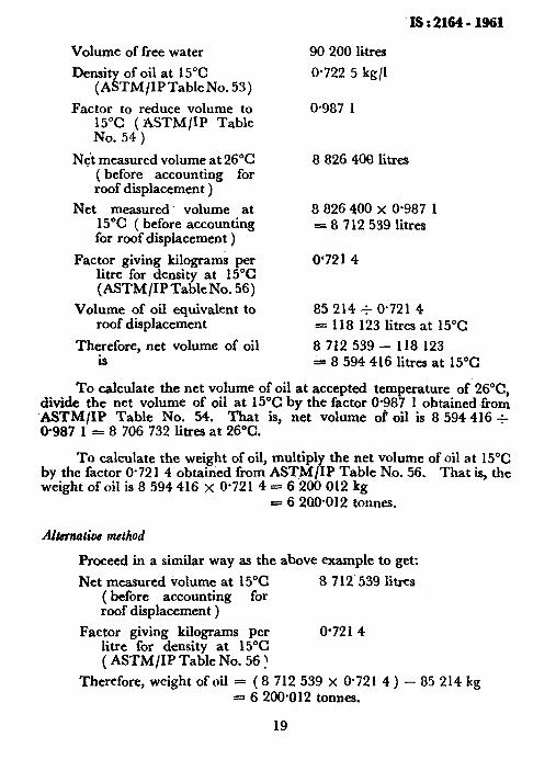
10.4.4 The followinn example illustrates the recommended procedure for calculating the quantity: _
Data True gross dip
True water dip Temperature of oil in tank Density of oil in tank
Weight of floating roof
Calculati0n.f Gross measured volume cor-
responding to the dip
-@lo6 m
0%82 m 26’C @715 0 kg/l at 24°C
85 214 kg
-8 916 600 litres
18
IS:2164-1961
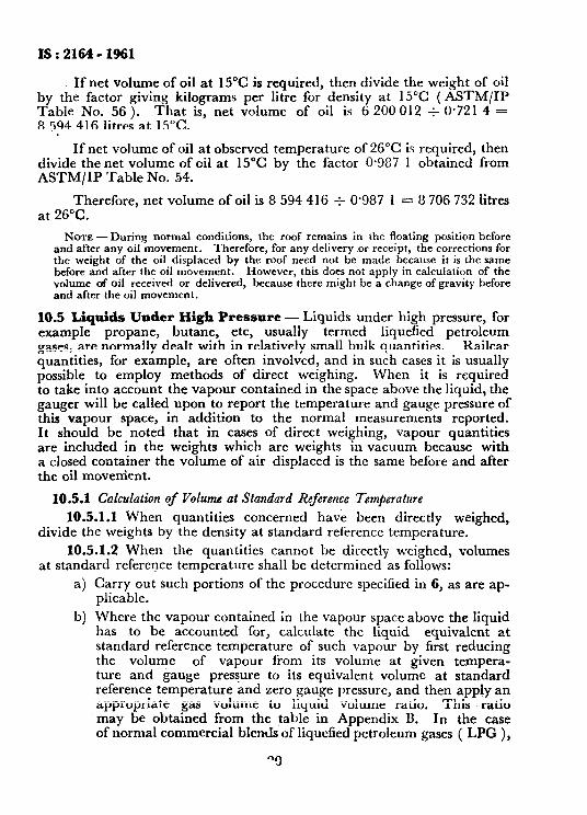
If net volume of oil at 15°C is required, then divide the weight of oil by the factor giving kilograms per litre for density at 15°C ( ASTM/IP Table No. 56 ). That is, net volume of oil is 6 200 012 f 0.721 4 = 8 594 416 litres at 15°C.
If net volume of oil at observed temperature of 26°C is required, then divide the net volume of oil at 15°C by the factor O-987 1 obtained from ASTM/IP Table No. 54.
Therefore, net volume of oil is 8 594 416 f 0.987 1 = 8 706 732 litres at 26°C.
NOTE -During normal conditions, the roof remains in the floating position before and after any oil movement. Therefore, for any delivery nor receipt, the corrections for the weight of the oil displaced by the roof need not be made because it is the same before and after the oil movement. However, this does not apply in calculation of the volume of oil received or delivered, because there might be a change of gravity before and after the oil movement.
10.5 Liquids Under High Pressure- Liquids under high pressure, for example propane, butane, etc, usually termed liquefied petroleum gases, are normally dealt with in relatively small bulk quantities. Kailcar quantities, for example, are often involved, and in such cases it is usually possible to employ methods of direct weighing. When it is required to take into account the vapour contained in the space above the liquid, the gauger will be called upon to report the temperature and gauge pressure of this vapour space, in addition to the normal measurements reported. It should be noted that in cases of direct weighing, vapour quantities are included in the weights which are weights in vacuum because with a closed container the volume of air displaced is the same before and after the oil movement.
10.5.1 Calculation of Volume at Standard Reference Temperature
10.5.1.1 When quantities concerned have been directly weighed, divide the weights by the density at standard reference temperature.
10.5.1.2 When the quantities cannot be directly weighed, volumes at standard reference temperature shall be determined as follows:
a)
b)
Carry out such portions of the procedure specilied in 6, as are ap- plicable,
Where the vapour contained in the vapour space above the liquid has to be accounted for, calculate the liquid equivalent at standard reference temperature of such vapour by first reducing the volume of vapour from its volume at given tempera- ture and gauge pressure to its equivalent volume at standard reference temperature and zero gauge pressure, and then apply an appropriate gas volume to liquid volume ratio. This ratio may be obtained from the table in Appendix I$. In the case of normal commercial blends of liquefied petroleum gases ( LPG ),
“3
IS : 21W- 1961
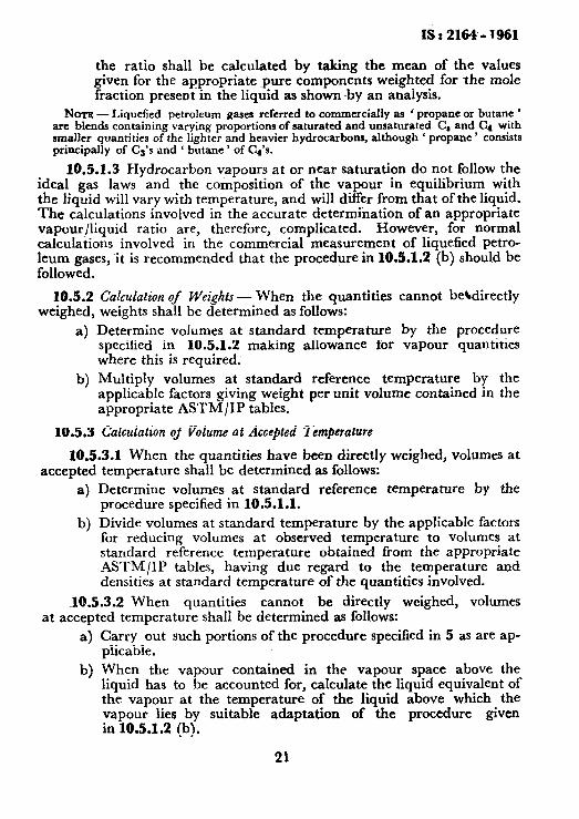
the ratio shall be calculated by taking the mean of the values given for the appropriate -pure components weighted for the mole fraction present in the liquid as shown ~by an analysis.
NOTE - Liquefied petroleum gases referred to commercially as ’ propane or butane ’ arc blends containing varying proportions of saturated and unsaturated C, and C4 with smaller quantities of the lighter and heavier hydrocarbons, although ‘ propane ’ consists principally of Ca’s and ‘ butane ’ of Cp’s.
10.5.1.3 Hydrocarbon vapours at or near saturation do not follow the ideal gas laws and the co&position of the vapour in equilibrium with the liquid will vary with temperature, and will differ from that of the liquid. The calculations involved in the accurate determination of an appropriate vapour/liquid ratio are, therefore, complicated. However, for normal calculations involved in the commercial measurement of liquefied petro- leum gases, it is recommended that the procedure in 10.5.1.2 (b) should be followed.
10.5.2 Calculation of Weights - When the quantities cannot bekdirectly weighed, weights shall be determined as follows:
a) Determine volumes at standard temperature by the procedure specified in 10.5.1.2 making allowance for vapour quantities where this is required.
b) Multiply volumes at standard reference temperature by the applicable factors giving weight per unit volume contained in the appropriate ASTM/IP tables.
10.5.3 Calculation of Volume at Accepted Temperature
10.5.3.1 When the quantities have been directly weighed, volumes at accepted temperature shall be determined as follows:
a) Determine volumes at standard reference temperature by the procedure specified in 10.5.1.1.
b) Divide volumes at standard temperature by the applicable factors for reducing volumes at observed temperature to volumes at standard reference temperature obtained from the appropriate ASTM/IP tables, having due regard to the temperature sod densities at standard temperature of the quantities involved.
10.5.3.2 When quantities cannot be directly weighed, volumes at accepted temperature shall be determined as follows:
a>
b)
Carry out such portions of the procedure specified in 5 as are ap- plicable.
When the vapour contained in the vapour space above the liquid has to be accounted for, calculate the liquid equivalent of the vapour at the temperature of the liquid above which the vapour lies by suitable adaptation of the procedure given in 10.5.1.2 (b).
21
I!3:2164-1961
c) When applicable, treat the vapour space calculations carried out as specified in 10.5.3.2 (b) as for separate containers and add the net results of such calculation to those obtained in (a) above.
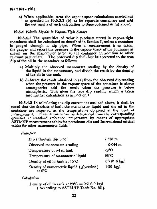
103.4 VolatiLe Liquids in Vap-Tight Storage
10.5.4.1 The quantities of volatile products stored in vapour-tight containers shall be calculated as described in Section I, unless a container is gauged through a dip pipe. When a measurement is so taken, the gauger will report the pressure in the vapour space of the container as shown on the manometer fitted to the container, in addition to other relevant particulars. The observed dip shall first be corrected to the true dip of the oil in the container as follows:
a) Multiply the observed manometer reading by the density of the liquid in the manometer, and divide the result by the density of the oil in the tank.
b) Subtract the result obtained in (a) from the observed dip reading when the pressure in the vapour space of the container is above atmospheric; add the result when the pressure is below atmospheric. This gives Ihe true dip reading which is taken into further calculation as in Section I.
10.5.4.2 In calculating the dip corrections outlined above, it shall be noted that the densities of both the manometer liquid and the oil in the container are required at the temperatures obtained at the time of measurement. These densities can be determined from the corresponding densities at standard reference temperature by means of appropriate ASTM/IP measurement tables for petroleum oils and International critical tables for other manometric fluids.-
Dip ( through dip pipe )
Observed manometer reading
Temperature of oil in tank
Temperature of manometric liquid
Density of oil in tank at 15°C
Der$y6oLmanometric liquid ( glycerine ) 0
Cal4xlutions
7.358 m
-0W-4 m
29°C
25°C
0*?18 6 kg/l
1.26 kg/I
Density of oil in tank at 29% = O-706 9 kg/l ( According to ASTM/IP Table No. 53 ).
22
Isr2164-1961
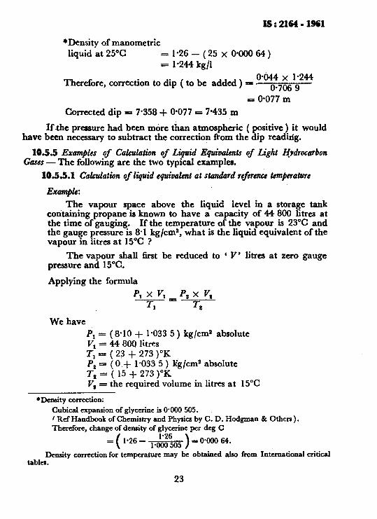
*Density of manometric liquid at 25°C =1~26~(25x@OOO64)
= 1.244 kg/l
Therefore, correction to dip ( to be added ) = ~“~7&.~M
= O-077 m
Corrected dip = 7.358 + @077 = 7.435 m
If the pressure had been more than atmospheric ( positive ) it would have been necessary to subtract the correction from the dip reading.
105.5 Examples of Calculation of Liquid Equioaknts of Light &drocarbon GarGS - The following are the two typical examples.
10.55.1 Calculation of liquid equivalent at standard rtftienct &m#erature
Exampk:
The vapour space above the liquid level in a storage tank containing propane is known to have a capacity of 44 800 litres at the time of gauging. If the temperature of the vapour is 23% and the gauge pressure is 8-l kg/ems, what is the liquid equivalent of the vapour in litres at 15°C ?
The vapour shall first be reduced to ‘ V’ litres at zero gauge pressure and 15°C.
Applying the formula
PI x v, 7”
ps x v, r,
We have PI = (8.10 + l-033 5) kg/cm2 absolute
= 44 800 litres : = ( 23 + 273 )“K Pz = ( 0 + I.033 5 ) kg/cm2 absolute T2 = ( 15 + 273 )“K v, = the required volume in litres at 15°C
Wensity correction:
Cubical expansion of glycerine is 0900 505. , f Ref Handbook of Chemistry and Physics by C. D. Hodgman & Others ) . Therefore, change of density of glycerine per deg C
= 1.26 - l.zM5 ) (
= 0300 64.
Density correction for temperature may be obtained also from International critical tables.
23
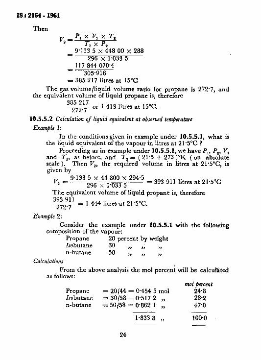
Then
v2 = PI x v, x 7-s
Tl x p. 9.133 5 x 448 00 x 288 =
296 x 1.033 5 117 844 070.4 S
305.916 = 385 217 lines at 15°C
The gas volume/liquid volume ratio for propane is 272.7, and the equivalent volume of liquid propane is, therefore
385 217 272.7
or 1 413 litres at 15°C.
10.5.5.2 Calculation of liquid equivalent at observed temjerature
Example 1:
In the conditions given in example under 10.5.5.1, what is the liquid equivalent of the vapour in litres at 21~5°C ?
Proceeding as in example under 10.5.5.1, we have PI. Pz, VI and T,,, as before, and Tz = ( 2 1.5 + 273 )“K ( on absolute scale ). Then V,, the required volume in litres at 21*5”C, is given by
V -P’133 5 ’ _--_ 44 8oo ’ 2g4*5 z- 296 kO33 5
= x
393 911 litres at 21.50~
The equivalent volume of liquid propane is, therefore 393 911 - = 1 444 litres at 21.5%.
272.7
Example 2:
Consider the composition of the
Propane Isobutane n-butane
Calculations
example under 10.5-5.1 with the following vapour:
20 percent by weight 36 ,, ,; 9, 50 3, ,, 2,
From the above analysis the mol percent will be calculated as follows:
mol @went Propane = 20144 = @454 5 mol 24.8 Isobutane = 30{58 = O-517 2 ,, 28-2 n-butane = 50158 = 0.862 1 ,, 47.0
l-833 8 ,, 100.0
24
Is : 2164 - ‘1961
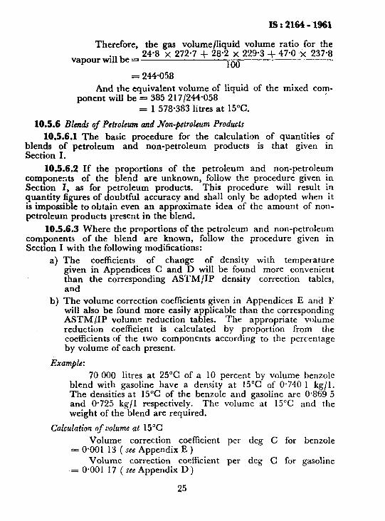
Therefore, the gas volume/liquid volume ratio for the
vapour will be r= 24.8 x 272.7 + 28.2 x 229.3 + 47.0 x 237.8
100 = 244.058
And the equivalent volume of liquid of the mixed com- ponent will be = 385 2 17 /244*058
= 1 578.383 litres at 15°C.
10.5.6 Blends of Petroleum and Non-petroleum Products
10.5.6.1 The basic procedure for the calculation of quantities of t$nnn ;f petroleum and non-petroleum products is that given in
e’ .
10.5.6.2 If the proportions of the petroleum and non-petroleum components of the blend are unknown, follow the procedure given in Section I, as for petroleum products. This procedure will result in quantity figures of doubtful accuracy and shall only be adopted when it is impossible to obtain even an approximate idea of the amount of non- petroleum products present in the blend.
10.5.6.3 Where the proportions of the petroleum and non-petroleum components of the blend are known, follow the procedure given in Section I with the following modifications:
a>
b)
The coefficients of change of density with temperature given in Appendices C and D will be found more convenient than the corresponding ASTM/IP density correction tables, and The volume correction coefficients given in Appendices E and F will also be found more easily applicable than the corresponding ASTM,LIP volume reduction tables. The appropriate volume reduction coefficient is calculated by proportion from the coefficients of the two components according to the percentage by volume of each present.
Examjle:
70 000 litres at 25°C of a 10 percent by volume benzole blend with gasoline have a ~density at 15°C of 0.740 l kg/l. The densities at 15°C of the benzole and gasoline are 0,869 5 and O-725 kg/l respectively. The volume at 15°C and the weight of the blend are required.
Calculation of volume at 15°C
Volume correction coefficient per deg C for benzole = O*OOl 13 ( see Appendix E )
Volume correction coefficient per deg C for gasoline = O-00 1 17 ( see Appendix D )
25

IS:2164-1961
Therefore, the volume correction coefficient per deg C for blend = 10 percent of 0.001 13 + 90 percent of 0.001 17
= 0.001 166
The volume of oil is to be reduced over 10°C ( from 25°C to 15°C)
Therefore, reduction of unit volume
Reduction of 70 000 litres
and, volume at 15°C
= 0.001 166 x 10 = 0.011 66 = 70 000 x 0*01166 = 816.2 litres z= 70 000 - 816.2 = 69 183-8 litres
Calculation of weight
= 69 184 ( after rounding off to litre )
Calculation of weight is the same as in the procedure outlined in Section I, using appropriate ASTM/IP weight/volume tables, entered with the density at 15°C.
One litre at 15°C of an oil whose density at 15°C is O-740 1 kgJ1 weighs 0.739 0 kg in air ( ASTM/IP Table No. 56 ).
Therefore, 69 184 litres at 15°C will weigh 69 184 x O-739 0 kg = 51126.98 kg = 51 127 kg = 51.127 tonnes
APPENDIX A
( Clause 0.3.1 ) A SHORT METHOD OF WEIGHT CALCULATION FOR
SMALL QUANTITIES
A-l. METHOD
A-l.1 The method prescribed is simple in as far as ‘the use of~ASTM{IP petroleum measurement tables is avoided. It can be relied upon to give results correct to. two places of decimal of a tonne and is intended primarily for the calculation of weights of furnace oil and light diesel oil moved in tank carts, tank lorries and rail tank wagons.
A-2. CORRECTION COEFFICIENTS
A-2.1 If a sample is drawn from a tank lorry, tank wagon, etc, for deter- mination of density, and the temperature of the sample differs by more
26

IS : 2164 - 1961
than @5”C from that of the oil in the tank. lorry, tank wa on, etc, the sample density may be corrected to the temperature of t f e oil in the tank lorry, tank wagon, etc, using the following density correction co- efficients:
Furnace oil
Light diesel oil
A-3. CALCULATION
O*OOO 63 per deg C
O*OOO 65 per deg C
A-3.1 The following formula may be used for the calculation of weights of small parcels carried in tank carts, tank lorries and rail tank wagons:
Weight in tonnes = V(D-F)
1000
where
V = volume in litres of oil at temperature T”C,
D = density of oil measured with a density hydrometer calibrated at 15”C, and
F = factor for converting weight -in vacuum to weight in air.
= O*OOO 02 ( 40 + T) where T is in “C.
= 0.001 1 (at 15°C ).
A-4. EXAMPLE
AA.1 The following example illustrates the use of this short method:
A rail tank wagon contains 20 000 litres of furnace oil at a temperature of 29°C. A sample drawn from the tank wagon was found to have a density of O-924 5 at a temperature of 28*$%. To determine the weight of the oil in the tank wagon:
Data
Density at 28.5% Density correction coefficient
Therefore density at 29°C
Factor F
27
= 0.924 5 kg/l
= O*OOO 63~per deg C = 0.924 5 - O~COO3 m= O-924 2 kg/l
=0*00002 (40+29) = 0.001 38
= 0’001 4
IS : 2164 - 1961
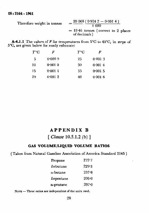
Therefore weight in tonnes 20 000 = ( 0.924 2 - 0.001 4 ) 1 600
= 18.46 tonnes ( correct to 2 places of decimals )
A-4.1.1 The values of F for temperatures from 5°C to 4O”C, in steps of 5X, are given below for ready reference:
T”C F T”C F
5 o*ooo 9 25 O*OOl 3
10 0~001 0 30 0.001 4
15 0.001 1 35 0.0015
20 0.001 2 40 0.001 6
APPENDIX -B
[ Clause 10.5.1.2 (b) ]
GAS VOLUME/LIQUID VOLUME RATIOS
(Taken from Natural Gasoline Association of America Standard 2145 )
Propane 272.7
Isobutane 229.3
n-butane 237.8
Isopentane 205.0
n-pentane 207.0
NOTE - These ratios are independent of the units used.
28
IS t 2164 - 1961
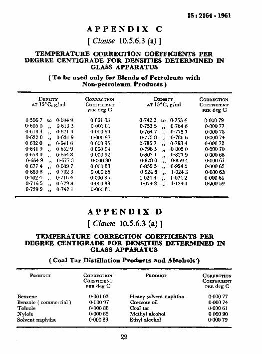
APPENDIX C
[ Chse 1056.3 (a) ]
TEMPERATURE CORRECTION COEFkICIENTS PER DEGREE CENTIGRADE FOR DENSITIES DETERMINED IN
GLASS APPARATUS
( To be used only for Blends of Petroleum with Non-petroleum Products )
DENSITY AT 15°C g/ml
0.596 7 to 0.604 9 0.605 0 ,, 0.613 3 0.613 4 ,, 0.621 9 O-622 0 ,, 0.631 9 0.632 0 ,, 0.641 8 06419 ,, 0.652 9 0.6530 ,, 0.6648 0.664 9 0.677 3 0.6774 :: 0.689 7 0689 8 ,, 0.702 3 0.7024 ,, 0.7164 0.716 5 ,, 0.729 8 0.729 9 ,) 0.742 1
CORRECTION COEFFICIENT PER deg C
0.001 03 0.001 01 0.000 99 0.000 97 0.000 95 0.000 94 0.000 92 0.000 90 0.000 88 0.000 86 0.000 85 0.000 83 0.000 8 1
DENSITY AT 15"C, g/ml
0.7422 to 0.7534 0,753 5 ,, O-764 6 0.764 7 ,) 0.775 7 0.775 8 0.786 6 O-786 7 ;: O-798 4 O-798 5 ,, 0.802 0 0.802 1 ,, 0.827 9 0.828 0 ,, 0,859 4 0.859 5 ), 0.924 5 O-924 6 1.024 3 1.024 4 ,; 1.074 2 1.0743 ,, l-124 1
CORRZCTION COEFFICIENT PER deg C
o+KIo 79 0.000 77 0.000 76 0.000 74 O@OO 72 0.000 70 0.000 68 0X100 67 O-000 65 OWO 63 OWO 61 OGNI 59
APPENDIX D
[ Clause 1056.3 (a)]
TEMPERATURE CORRECTION COEFFICIENTS PER DEGREE CENTIGRADE FOR DENSITIES DETERMINED IN
GLASS APPARATUS
( Coal Tar Distillation Products and Alcohols*)
PROWCT CORRECTION COEFFICIENT
PER deg C
-BROnUCT CORRECTIUN COEPFICIRNT
PER deg C
Benzene 0.001 03 Heavy solvent naphtha o*ooo 77 Benzole ( commercial ) 0.000 97 Creosote oil O*OOO 74 Toluole 0.000 88 coal tar O-000 6 1 Xylole 0.000 85 Methyl alcohol 0.000 90 Solvent naphtha O-000 83 Ethyl alcohol o*ooo 79
29
IS : 2164 - 19fif
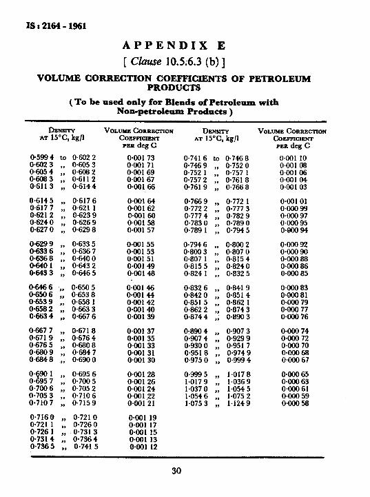
APPENDIX E
[ Clause 10.5.6.3 (b) ]
VOLUME COBRECTION COEFFICIENTS PRODUCTS
OF PETROLEUM
-( To be used only for Blends of Petroleum with Non-petroleum Prodacts )
DENSITY AT 15”c, kg/l
o-599 4 to O-602 2 O-602 3 ,, o-6053 o-605 4 ,, 06082 0.608 3 ,, O-611 2 O-61 1 3 ,, O-6144
0.614 5 ,, 0.617 6 O-617 7 ,, 0.621 1 0.621 2 ,, 0.623 9 O-624 0 ,, O-626 9 O-627 0 ,, O-629 8
;:62; ,, ,, O-6335 O-636 7 0.6368 ,, O-640 0 06401 ,, 0.6432 o-643 3 ,, 06465
06466 ‘,, 0.6505 O-650 6 ,, O-6538 o-653 9 ,, o-658 1 0.658 2 ,, o-6633 0.663 4 ,, O-667 6
0.667 7 ,, O-671 8 O-671 9 ,, 0.6764 O-676 5 ,, 06808 0680 9 ,, 0.6847 O-684 8 ,, 0.690 0
0. zi 901 ,, 0.695 6 0. 957 ,) 0.7005 O-700 6 ,, 0.705 2 o-705 3 ,, O-7106 o-710 7 ,, o-7159
0.716 0 ,, 0.721 0 O-721 1 ,, O-7260 O-726 1 ,, 0.731 3 0.731 4 ,, O-7364 0.7365 ,, O-741 5
VOLUMR CORREtXION coEFnuENT PBR deg C
oaJ1 73 om1 71 O+tO169 0.001 67 O-001 66
om164 0+0162 om160 O-001 58 oaJ157
0*00155 0*00153 O-001 51 oaO149 0*00148
O-001 46 oaO144 O-001 42 oao14O oaO139
O-001 37 OaOl 35 O-001 33 O-001 31 O*OOl 30
O-001 28 ONJI 26 O-001 24 om122 0@0121
OaOl 19 O-001 17 O-001 15 O-001 13 O*OOl 12
DENSITY AT 15”c, kg/l
0.741 6 to 0.746 8 o-746 9 ,, 0.752 0 0.752 1 ,, 0.757 1 0.757 2 ,, O-761 8 O-761 9 ,, 0.7668
o-766 9 ,, 0.772 1 O-772 2 ), o-777 3 o-777 4 ,, 0.782 9 O-783 0 ,, O-789 0 O-789 1 ,, 0.7945
0.794 6 ,, 0.8002 O-800 3 ,, O-807 0 0.807 1 ,, O-815 4 0.815 5 ,, 0.8240 O-824 1 ,, 0.832 5
O-832 6 ,, O-841 9 0.842 0 ,, O-851 4 O-851 5 ,, 0.862 1 o-862 2 ,, 0.874 3 0.8744 ,, O-890 3
0.890 4 ,, O-907 3 0*907 4 ,, 0.9299 o-9300 ,, 0.951 7 O-951 8 ,, 0.974 9 o-975 0 ,, o-9994
0.9995 ,,, 1.0178 1.017 9 ,, l-0369 l-0370 ,, l-054 5 l-0546 ,, 1.075 2 1.075 3 ,, l-1249
VOLUME CORRECTION C~EF~C~ENT PER deg C
O-001 10 0@0108 oaO106 0aO104 0aO103
0*00101 0wJO 99 oaOo 97 0aOO 95 o*QOo 94
0aOo 92 o*OOo 90 oaoa 88 oaoO86 OGXI 85
OWO 83 O-000 81 o*m 79 o+Oo 77 0.000 76
OaOO 74 O+@O 72 0aOo 70 oaoO-68 OX@0 67
OWO 65 O-000 63 O-000 61 omo 59 0aoO 58
30
fSr2164-1961
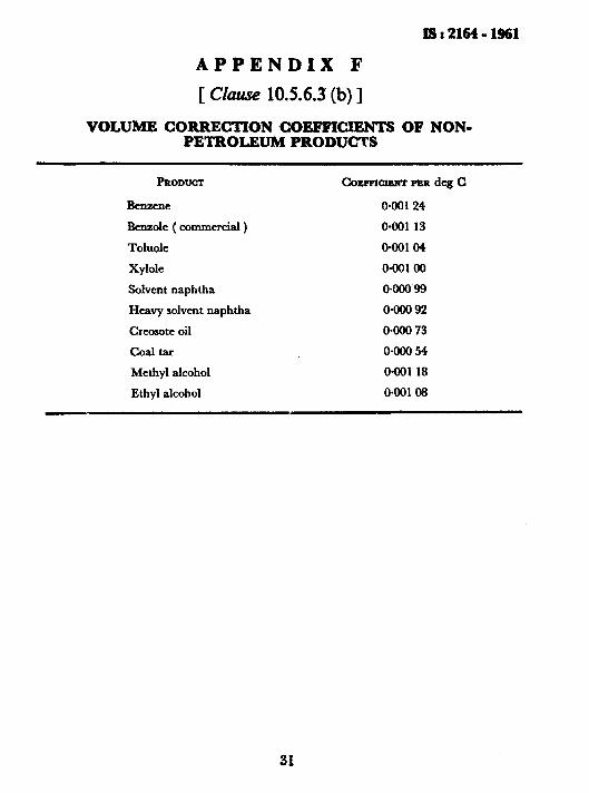
APPENDIX F
[ Clause 1056.3 (b) ]
VOLUME CORRECTION COEFFICIENTS OF NON- PETROLEUM PRODUCTS
PRODUCC
Benzene
Benzole ( commercial )
Toluole
Xylole
Solvent naphtha
Heavy solvent naphtha
Creosote oil
coal tar
Methyl alcohol
Ethyl alcohol
COSFFX- PER deg C
OGO124
O*OOl 13
O-001 04
O-001 00
O-000 99
OmO 92
0wO 73
0mO 54
O-001 18
0*00108
31
BUREAU OF INDIAN STANDARDS
Headquarters: Manak Bhavan, 9 Bahadur Shah Zafar Marg, NEW DELHI 110002 Telephones: 323 0131, 323 3375,323 9402 Fax : 91 11 3234062,91 11 3239399,91 11 3239382
Telegrams : Manaksanstha (Common to all Offices)
Central Laboratory: Telephone
Plot No. 20/9, Site IV, Sahibabad Industrial Area, Sahibabad 201010 8-77 0032
Regional Offices:
Central : Manak Bhavan, 9 Bahadur Shah Zafar Marg, NEW DELHI 110002 323 76 17
*Eastern : 1114 CIT SchemeVII M, V.I.P. Road, Maniktola, CALCUTTA700654 337 86 62
Northern : SC0 335-336, Sector 34-A, CHANDIGARH 160022 60 38 43
Southern : C.I.T. Campus, IV Cross Road, CHENNAI 600113 235 23 15
t Western : Manakalaya, E9, Behind Marol Telephone Exchange, Andheri (East), 832 92 95 MUMBAI 400093
Branch Offices:
‘Pushpak’, Nurmohamed Shaikh Marg, Khanpur, AHMEDABAD 380001 550 13 48
$ Peenya Industrial Area, 1 st Stage, Bangalore-Tumkur Road 839 49 55 BANGALORE 560058
Gangotri Complex, 5th Floor, Bhadbhada Road, T.T. Nagar, BHOPAL 462003 55 40 21
Plot No. 62-63, Unit VI, Ganga Nagar, BHUBANESHWAR 751001 40 36 27
Kalaikathir Buildings, 670 Avinashi Road, COIMBATORE 641037 21 01 41
Plot No. 43, Sector 16 A, Mathura Road, FARIDABAD 121001 8-28 88 01
Savitri Complex, 116 G.T. Road, GHAZIABAD 201001 8-71 19 96
53/5 Ward No. 29, R.G. Barua Road, 5th By-lane, GUWAHATI 781003 541137
5-8-56C, L.N. Gupta Marg, Nampally Station Road, HYDERABAD 500001 20 10 83
E-52, Chitaranjan Marg, C-Scheme, JAIPUR 302001 37 29 25
117/418 8, Sarvodaya Nagar, KANPUR 208005 21 68 76
Seth Bhawan, 2nd Floor, Behind Leela Cinema, Naval Kishore Road, 23 89 23 LUCKNOW 226001
NIT Building, Second Floor, Gokulpat Market, NAGPUR 440010
Patliputra Industrial Estate, PATNA 800013
Institution of Engineers (India) Building 1332 Shivaji Nagar, PUNE 411005
TC. No. 14/1421, University PO. Palayam, THIRUVANANTHAPURAM 695034
5251 71
26 23 05
32 36 35
621 17
*Sales Office is at 5 Chowringhee Approach, PO. Princep Street, CALCUTTA 700072
27 10 85
tSales Office is at Novelty Chambers, Grant Road, MUMBAI 400007
*Sales Office is at ‘F’ Block, Unity Building,-Narashimaraia Square, BANGALORE 560002
309 65 28
222 39 71
Printed at Simco Printing Press. Delhi, India