Embed Size (px)
Citation preview
I
University Politehnica of Bucharest
Faculty of Electronics, Telecommunication and Information Technology
Master Program
(Advanced Wireless Telecommunications Program)
IPsec VPN topology over GRE Tunnels
(Implementation with GNS3)
Student:
Mustafa Khaleel
Year 2015
II
Contents 1. Introduction ............................................................................................................................ 1
1.1. VPN Categories and Benefits .......................................................................................... 2
1.2. VPN requirements .......................................................................................................... 2
2. BUSINESS CONSIDERATIONS .................................................................................................. 3
2.1. VPN DEPLOYMENT .......................................................................................................... 3
2.2. VPN Topology .................................................................................................................. 3
3. IPSEC (Internet Protocol Security) .......................................................................................... 4
3.1. Security Protocols for Traffic Security ............................................................................ 4
3.2. Modes of Operation........................................................................................................ 5
3.3. Key Exchange and Management .................................................................................... 6
4. GNS3 implementation ............................................................................................................ 7
5. Test and Results .................................................................................................................... 13
Reference ...................................................................................................................................... 17
Figure 1 VPN ................................................................................................................................................... 1
Figure 2 AH (Authentication Header) ............................................................................................................ 4
Figure 3 ESP (Encapsulated Security Payload) .............................................................................................. 5
Figure 4 Tunnel mode .................................................................................................................................... 5
Figure 5 Transport mode ............................................................................................................................... 5
Figure 6 topology full mesh 1b ...................................................................................................................... 7
Figure 7 PE1, PE2 and PE3 Routers ................................................................................................................ 7
Figure 8 Customer Routers ............................................................................................................................ 8
Figure 9 OSPF Routing for PE3 ....................................................................................................................... 8
Figure 10 OSPF Routing for PE2 ..................................................................................................................... 9
Figure 11 Routing Table of CN Router ........................................................................................................... 9
Figure 12 Routing Table of CSW Router ...................................................................................................... 10
Figure 13 Tunnels ......................................................................................................................................... 10
Figure 14 Tunnels ......................................................................................................................................... 11
Figure 15 Crypto ISAKMP ............................................................................................................................. 11
Figure 16 ISAKMP Policy .............................................................................................................................. 12
Figure 17 CN Tunnel and CSW Tunnel ......................................................................................................... 12
Figure 18 CSC tunnel and CSE tunnel........................................................................................................... 13
Figure 19 Connection between CN site and CSW site ................................................................................. 13
Figure 20 connection between CSC site and CSE site ................................................................................. 13
Figure 21 negotiation between two sites ................................................................................................... 14
Figure 22 Crypto Session for CSE Router ..................................................................................................... 15
Figure 23 Crypto Session for CSW Router ................................................................................................... 15
Figure 24 Packet Sending ............................................................................................................................. 16
Figure 25 encrypted the packets ................................................................................................................. 16
Figure 26 decrypted the Packet ................................................................................................................... 17
1
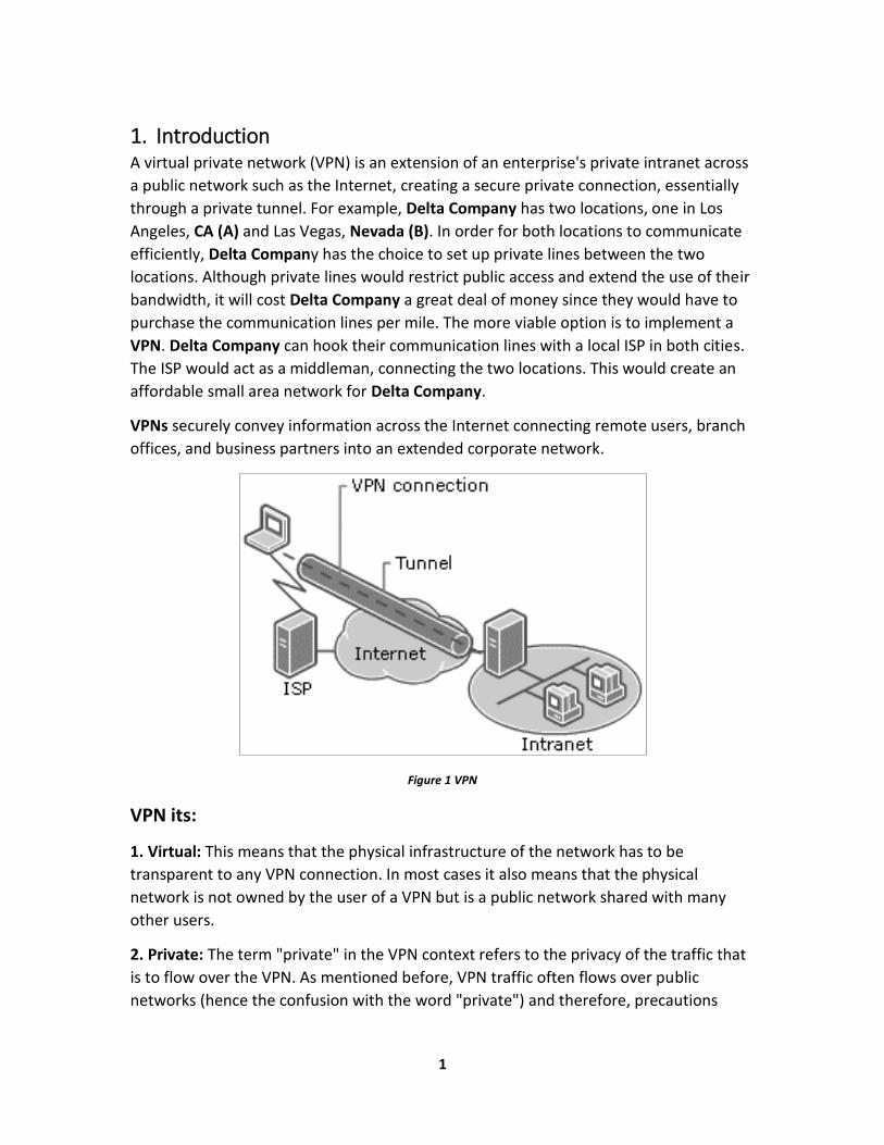
1. Introduction A virtual private network (VPN) is an extension of an enterprise's private intranet across
a public network such as the Internet, creating a secure private connection, essentially
through a private tunnel. For example, Delta Company has two locations, one in Los
Angeles, CA (A) and Las Vegas, Nevada (B). In order for both locations to communicate
efficiently, Delta Company has the choice to set up private lines between the two
locations. Although private lines would restrict public access and extend the use of their
bandwidth, it will cost Delta Company a great deal of money since they would have to
purchase the communication lines per mile. The more viable option is to implement a
VPN. Delta Company can hook their communication lines with a local ISP in both cities.
The ISP would act as a middleman, connecting the two locations. This would create an
affordable small area network for Delta Company.
VPNs securely convey information across the Internet connecting remote users, branch
offices, and business partners into an extended corporate network.
Figure 1 VPN
VPN its:
1. Virtual: This means that the physical infrastructure of the network has to be
transparent to any VPN connection. In most cases it also means that the physical
network is not owned by the user of a VPN but is a public network shared with many
other users.
2. Private: The term "private" in the VPN context refers to the privacy of the traffic that
is to flow over the VPN. As mentioned before, VPN traffic often flows over public
networks (hence the confusion with the word "private") and therefore, precautions
2
must be met to provide the necessary security that is required for any particular traffic
profile that is to flow over a VPN connection, (Data encryption and authentication.. etc.)
3. Network: means that it must be made available to the rest of the network, to all or a
specified 4 A Comprehensive Guide to Virtual Private Networks, Volume III subset of its
devices and applications, by regular means of topology such as routing and addressing.
Having said all that, "secure tunneled connections" may be a more appropriate term to
describe what a VPN technically is, but the term VPN has prevailed.
1.1. VPN Categories and Benefits
VPNs were are broken into 4 categories-
1. Trusted VPN: A customer “trusted” the leased circuits of a service provider and used it to communicate without interruption. Although it is “trusted” it is not secured.
2. Secure VPN: With security becoming more of an issue for users, encryption and decryption was used on both ends to safeguard the information passed to and fro. This ensured the security needed to satisfy corporations, customers, and providers.
3. Hybrid VPN: A mix of a secure and trusted VPN. A customer controls the secure parts of the VPN while the provider, such as an ISP, guarantees the trusted aspect.
4. Provider-provisioned VPN: A VPN that is administered by a service provider.
VPNs provide a very cost-effective means of private communication by using inexpensive local call ISDN or telephone connections (with the Internet as the backbone).
1.2. VPN requirements 1. Security: Confidentiality, integrity, access control.
2. Quality of Service: Availability. Performance: bandwidth, delay.
3. Low cost: Installation, operation.
3
2. BUSINESS CONSIDERATIONS
2.1. VPN DEPLOYMENT VPN is mainly employed by organizations and enterprises in the following ways:
1. Remote access VPN: This is a user-to-network connection for the home, or from a
mobile user wishing to connect to a corporate private network from a remote location.
This kind of VPN permits secure, encrypted connections between a corporate private
network and remote users.
2. Intranet VPN: Here, a VPN is used to make connections among fixed locations such as
branch offices. This kind of LAN-to-LAN VPN connection joins multiple remote locations
into a single private network.
3. Extranet VPN: This is where a VPN is used to connect business partners, such as
suppliers and customers, together so as to allow various parties to work with secure
data in a shared environment.
4. WAN replacement: Where VPN offers an alternative to WANs (Wide Area Networks).
Maintaining a WAN can become expensive, especially when networks are geographically
dispersed. VPN often requires less cost and administration overhead, and offers greater
scalability than traditional private networks using leased lines. However, network
reliability and performance might be a problem, in particular when data and
connections are tunneled through the Internet.
2.2. VPN Topology VPNs can be categorized as follows:
1. A firewall-based VPN is one that is equipped with both firewall and VPN
Capabilities. This type of VPN makes use of the security mechanisms in firewalls to
restrict access to an internal network. The features it provides include address
translation, user authentication, real time alarms and extensive logging.
2. A hardware-based VPN offers high network throughput, better performance and
more reliability, since there is no processor overhead. However, it is also more
expensive.
3. A software-based VPN provides the most flexibility in how traffic is managed. This
type is suitable when VPN endpoints are not controlled by the same party, and where
different firewalls and routers are used. It can be used with hardware encryption
accelerators to enhance performance.
4. An SSL VPN3 allows users to connect to VPN devices using a web browser. The SSL
(Secure Sockets Layer) protocol or TLS (Transport Layer Security) protocol is used to
encrypt traffic between the web browser and the SSL VPN device. One advantage of
4
using SSL VPNs is ease of use, because all standard web browsers support the SSL
protocol, therefore users do not need to do any software installation or configuration.
3. IPSEC (Internet Protocol Security) IPsec was developed by IETF (the Internet Engineering Task Force) for secure transfer of
information at the OSI layer three across a public unprotected IP network, such as the
Internet. IPsec enables a system to select and negotiate the required security protocols,
algorithm(s) and secret keys to be used for the services requested. IPsec provides basic
authentication, data integrity and encryption services to protect unauthorized viewing
and modification of data. It makes use of two security protocols, AH (Authentication
header) and ESP (Encapsulated Security Payload), for required services. However, IPsec
is limited to only sending IP packets.
3.1. Security Protocols for Traffic Security IPsec makes use of the AH and ESP protocols to provide security services:
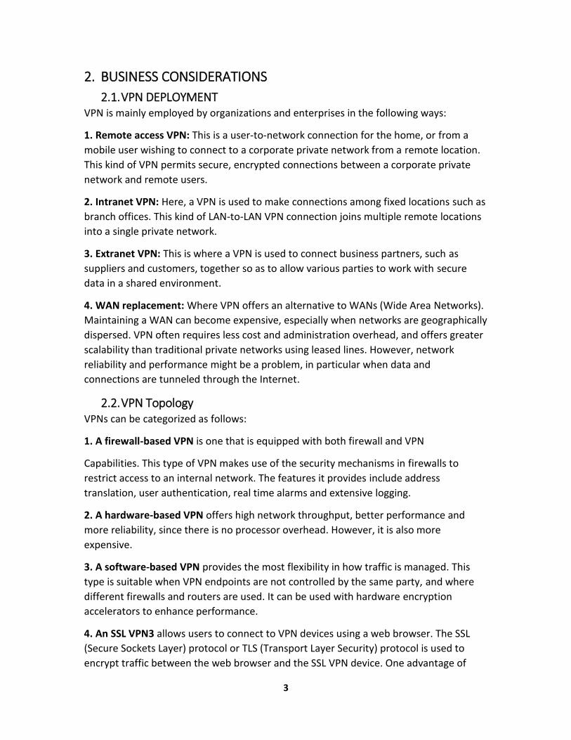
1. AH (Authentication Header) protocol provides source authentication, and integrity of
IP packets, but it does not have encryption. An AH header added to the IP packet
contains a hash of the data, a sequence number etc., and information that can be used
to verify the sender, ensure data integrity and prevent replay attacks.
Figure 2 AH (Authentication Header)
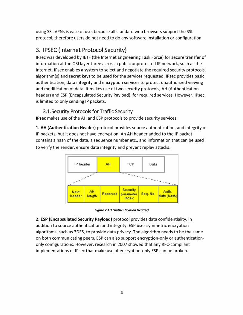
2. ESP (Encapsulated Security Payload) protocol provides data confidentiality, in
addition to source authentication and integrity. ESP uses symmetric encryption
algorithms, such as 3DES, to provide data privacy. The algorithm needs to be the same
on both communicating peers. ESP can also support encryption-only or authentication-
only configurations. However, research in 2007 showed that any RFC-compliant
implementations of IPsec that make use of encryption-only ESP can be broken.
5
Figure 3 ESP (Encapsulated Security Payload)
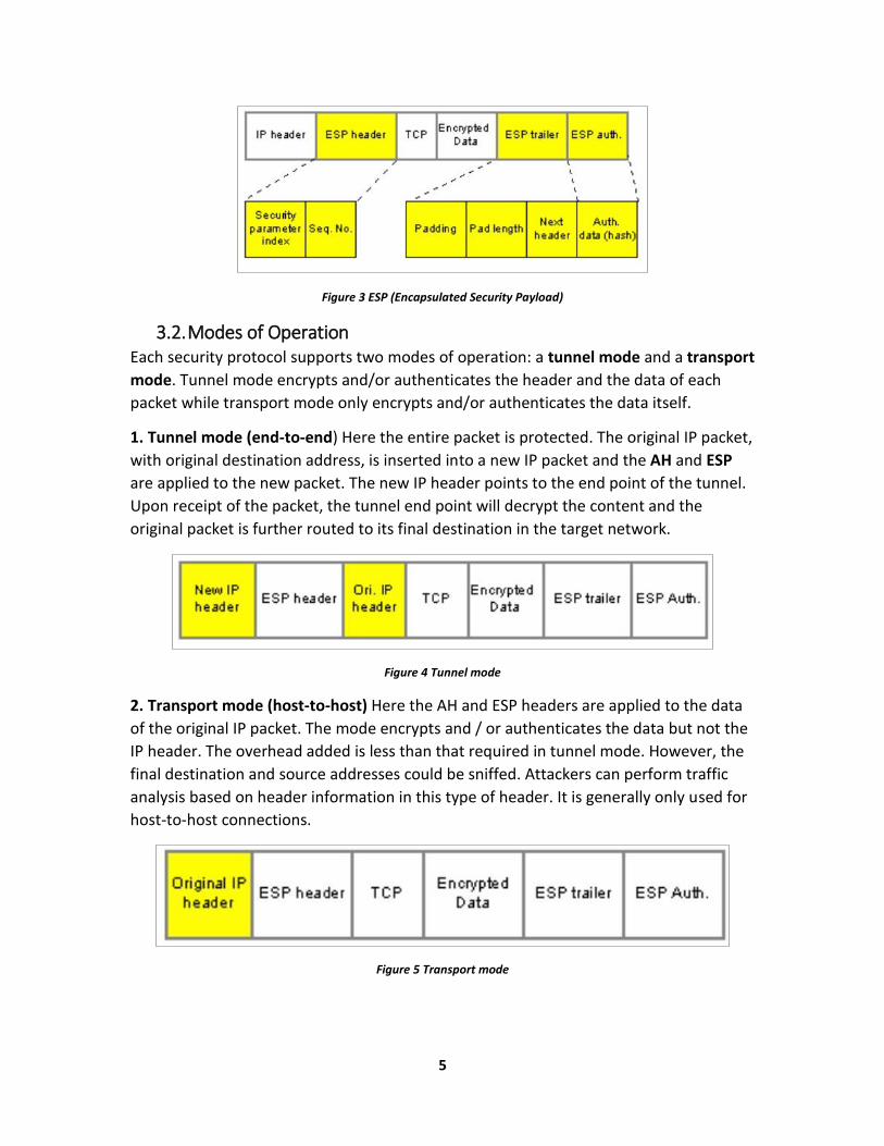
3.2. Modes of Operation Each security protocol supports two modes of operation: a tunnel mode and a transport
mode. Tunnel mode encrypts and/or authenticates the header and the data of each
packet while transport mode only encrypts and/or authenticates the data itself.
1. Tunnel mode (end-to-end) Here the entire packet is protected. The original IP packet,
with original destination address, is inserted into a new IP packet and the AH and ESP
are applied to the new packet. The new IP header points to the end point of the tunnel.
Upon receipt of the packet, the tunnel end point will decrypt the content and the
original packet is further routed to its final destination in the target network.
Figure 4 Tunnel mode
2. Transport mode (host-to-host) Here the AH and ESP headers are applied to the data
of the original IP packet. The mode encrypts and / or authenticates the data but not the
IP header. The overhead added is less than that required in tunnel mode. However, the
final destination and source addresses could be sniffed. Attackers can perform traffic
analysis based on header information in this type of header. It is generally only used for
host-to-host connections.
Figure 5 Transport mode
6
3.3. Key Exchange and Management 1. Automated Key Management IKE (Internet Key Exchange) IKE (Internet Key
Exchange) is the default protocol used in IPsec to determine and negotiate protocols,
algorithms and keys, and to authenticate the two parties. It is useful for widespread,
scalable deployments and implementations of VPN.
The IKEv2 protocol was released in 2005. It preserves most of the functionalities of
IKEv1 protocol, but also supports the Network Address Translation (NAT) traversal and
provides more flexibility. IKE also supports the use of digital certificates. Users
authenticate by first signing the data with their digital signature key.
The other endpoint will then verify the signature. IKE creates an authenticated, secure
tunnel between two entities, then negotiates a security association (SA) between the
two entities, and exchanges key(s). SA is a set of parameters used by negotiating peers
to define the services and mechanisms for protecting traffic. These parameters include
algorithm identifiers, modes, keys, and so on. IKE also keeps track of the keys and
updates them between communicating peers.
IKE uses protocols like ISAKMP (The Internet Security Association and Key Management
Protocol) and Oakley to define procedures for key generation, creation and
management of SA and authentication.
2. Manual key management: secret keys and security associations are manually
configured in both VPN communicating peers before a connection starts. Only the
sender and recipient know the secret key for the security services at hand. If the
authentication data is valid, the recipient knows that the communication came from the
sender and it was not modified. This approach is easy to use in small, static
environments, but it does not scale well. All keys should be distributed to
communicating peers securely beforehand. If the keys are compromised, another
person could pose as the user and make a connection into the VPN.
7
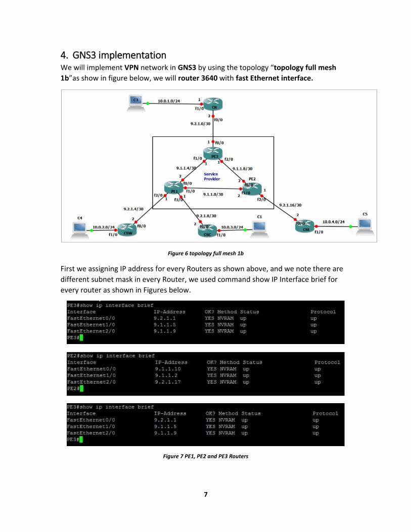
4. GNS3 implementation We will implement VPN network in GNS3 by using the topology “topology full mesh
1b”as show in figure below, we will router 3640 with fast Ethernet interface.
Figure 6 topology full mesh 1b
First we assigning IP address for every Routers as shown above, and we note there are
different subnet mask in every Router, we used command show IP Interface brief for
every router as shown in Figures below.
Figure 7 PE1, PE2 and PE3 Routers
8
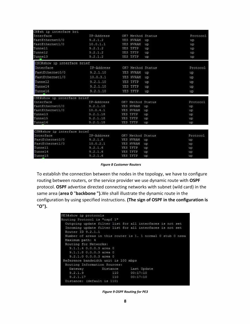
To establish the connection between the nodes in the topology, we have to configure
routing between routers, or the service provider we use dynamic route with OSPF
protocol. OSPF advertise directed connecting networks with subnet (wild card) in the
same area (area 0 "backbone ").We shall illustrate the dynamic route in the
configuration by using specified instructions. (The sign of OSPF in the configuration is
"O").
Figure 9 OSPF Routing for PE3
Figure 8 Customer Routers
9
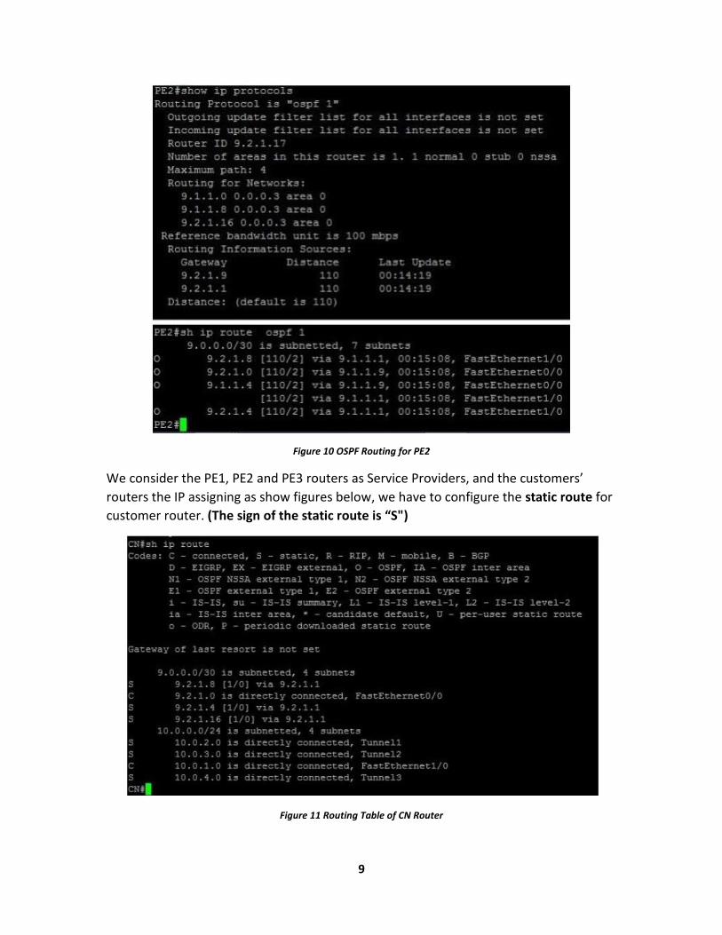
Figure 10 OSPF Routing for PE2
We consider the PE1, PE2 and PE3 routers as Service Providers, and the customers’
routers the IP assigning as show figures below, we have to configure the static route for
customer router. (The sign of the static route is “S")
Figure 11 Routing Table of CN Router
10
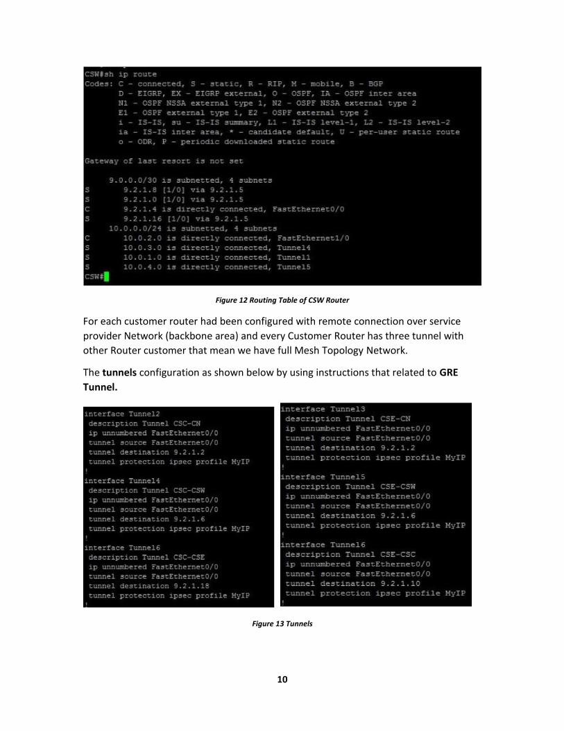
Figure 12 Routing Table of CSW Router
For each customer router had been configured with remote connection over service
provider Network (backbone area) and every Customer Router has three tunnel with
other Router customer that mean we have full Mesh Topology Network.
The tunnels configuration as shown below by using instructions that related to GRE
Tunnel.
Figure 13 Tunnels
11
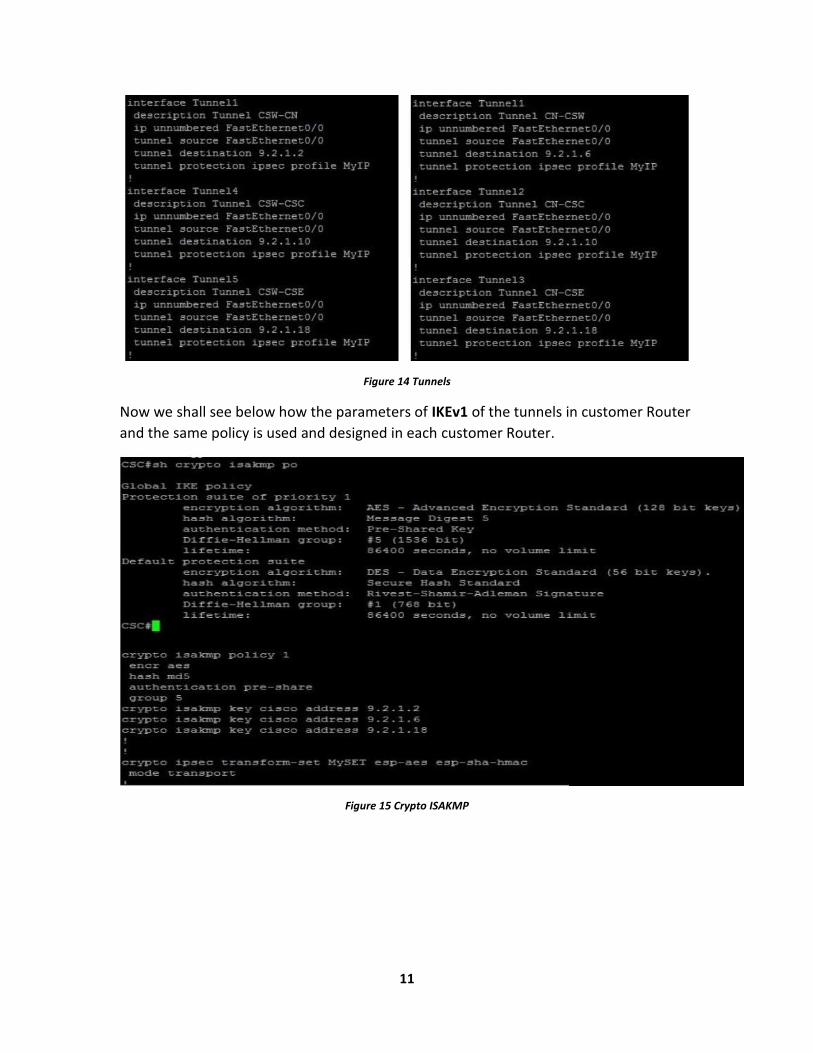
Figure 14 Tunnels
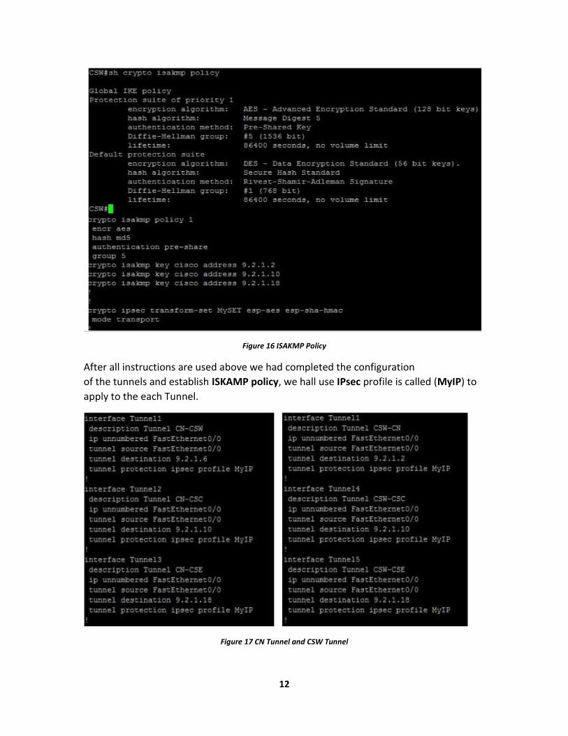
Now we shall see below how the parameters of IKEv1 of the tunnels in customer Router
and the same policy is used and designed in each customer Router.
Figure 15 Crypto ISAKMP
12
Figure 16 ISAKMP Policy
After all instructions are used above we had completed the configuration
of the tunnels and establish ISKAMP policy, we hall use IPsec profile is called (MyIP) to
apply to the each Tunnel.
Figure 17 CN Tunnel and CSW Tunnel
13
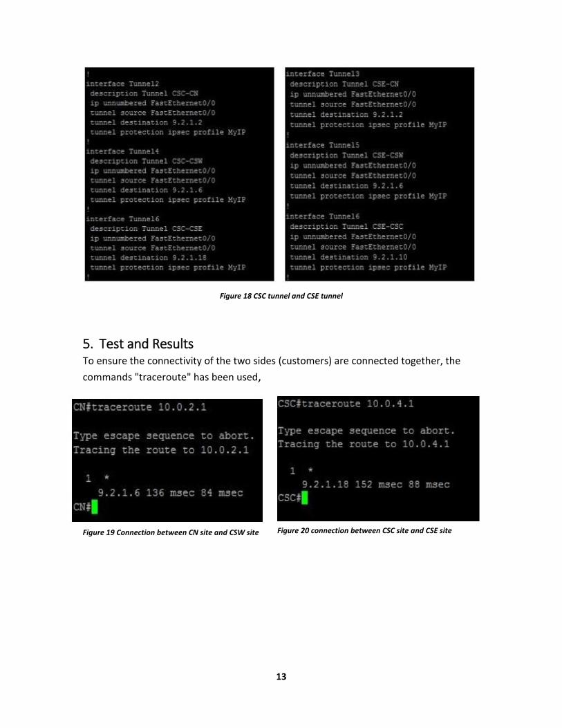
Figure 18 CSC tunnel and CSE tunnel
5. Test and Results To ensure the connectivity of the two sides (customers) are connected together, the
commands "traceroute" has been used,
Figure 19 Connection between CN site and CSW site Figure 20 connection between CSC site and CSE site
14
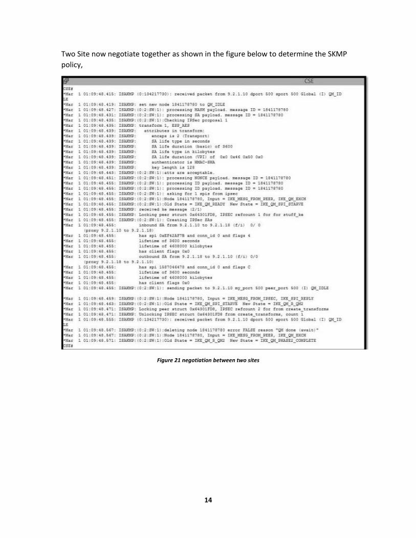
Two Site now negotiate together as shown in the figure below to determine the SKMP
policy,
Figure 21 negotiation between two sites
15
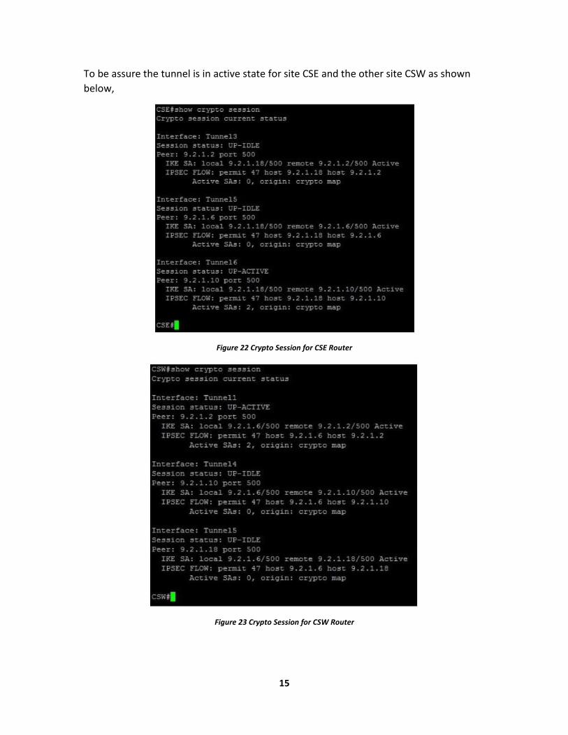
To be assure the tunnel is in active state for site CSE and the other site CSW as shown
below,
Figure 22 Crypto Session for CSE Router
Figure 23 Crypto Session for CSW Router
16
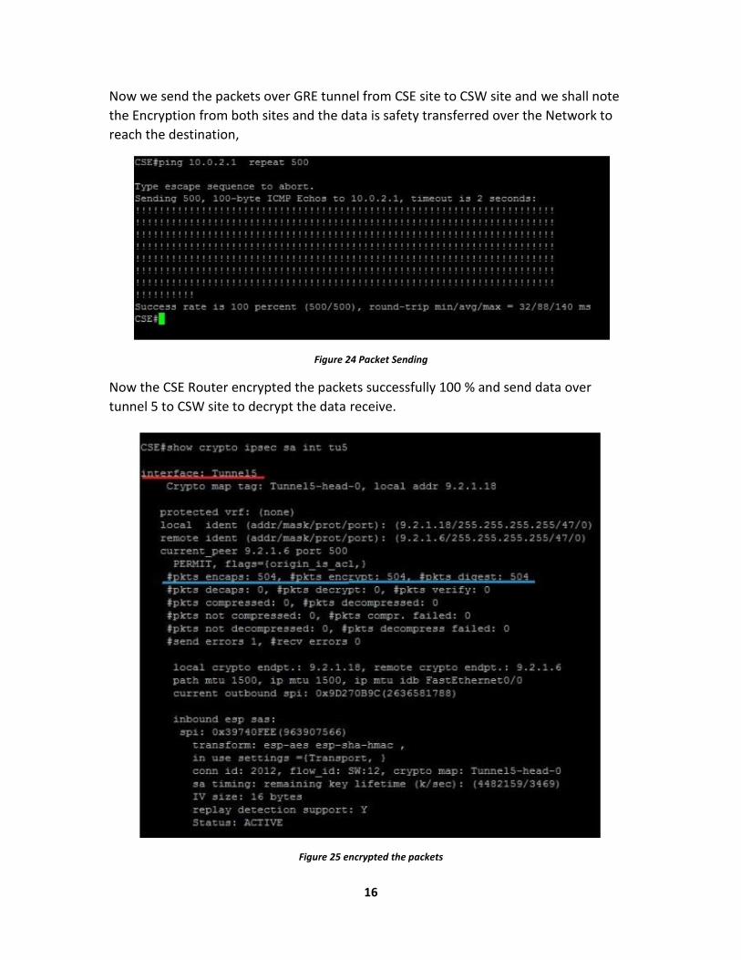
Now we send the packets over GRE tunnel from CSE site to CSW site and we shall note
the Encryption from both sites and the data is safety transferred over the Network to
reach the destination,
Figure 24 Packet Sending
Now the CSE Router encrypted the packets successfully 100 % and send data over
tunnel 5 to CSW site to decrypt the data receive.
Figure 25 encrypted the packets
17
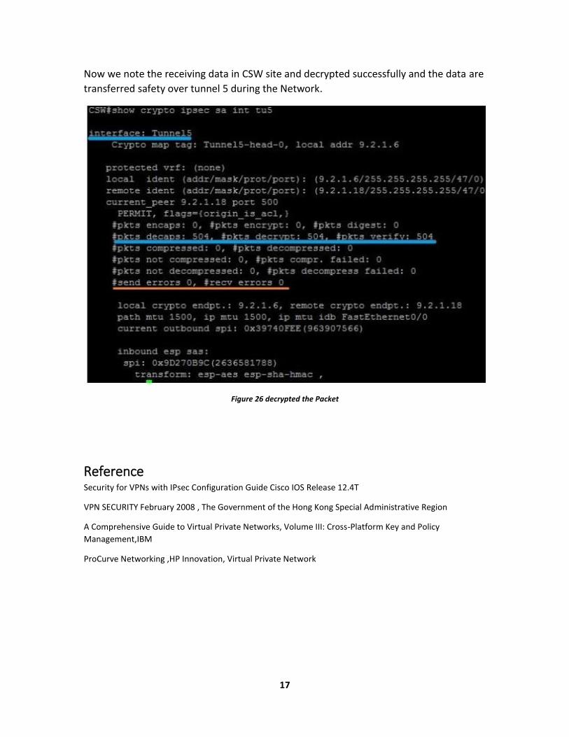
Now we note the receiving data in CSW site and decrypted successfully and the data are
transferred safety over tunnel 5 during the Network.
Figure 26 decrypted the Packet
Reference Security for VPNs with IPsec Configuration Guide Cisco IOS Release 12.4T
VPN SECURITY February 2008 , The Government of the Hong Kong Special Administrative Region
A Comprehensive Guide to Virtual Private Networks, Volume III: Cross-Platform Key and Policy
Management,IBM
ProCurve Networking ,HP Innovation, Virtual Private Network