Embed Size (px)
Citation preview

Variable Valve Lift

Presentation Overview General overview of the valvetrainIntroduction of variable valve lift and timing Valve flowHow VVL effects engine volumetric efficiency Camshaft terminologyCurrent VVL technology
Fiat/Chrysler MultiairHonda V-Tec BMW GMMercedes Benz Camtronics
Where valvetrain technology is headed

Why focus on the Valvetrain?Three major demands to automakers
Fuel economyLower emissionsPerformance
Continued pressure put on automakers to develop new technology to meet these demands
Performance, fuel economy, and emissions are interrelatedOnce physical engine parameters such as displacement, cam
profile, and compression ratio are set performance, fuel economy, and emissions and nearly fixed
Compression ratio for example, is fixed once components are chosen

Why focus on the Valvetrain?Optimum engine operating conditionsMost common engine operating condition
Low engine speeds/throttled air flowFluid friction and pumping losses

Why focus on the Valvetrain?Position of the crankshaft and the profile of the camshaft determine
the valve eventsDifferent operating conditions have different ideal valve event
schedules This is a significant compromise
ExampleCompression ratio is limited by range with lowest knock limit-ie
WOTHowever lower engine speeds have less tendency to knock and
can withstand higher compression ratios

Why focus on the Valvetrain?Technology developed to help improve performance, fuel economy,
and emissionsVariable valve actuation technology
Added control of valve timing, lift, and/or duration Efficiency improvementsCompression ratio increase possibleLoad control-Control airflow into engine without restrictionEGR (exhaust gas recirculation)

Camshaft Terminology Noteable terminology
Opening vs closing rampNoseBase circle HeelLift

Camshaft TerminologyWhat is lobe lift?
The amount of travel from the base circle of the camshaft up to the nose of the cam lobe
Lobe lift= (base circle and lobe lift) -base circle

Camshaft Terminology Cont. Duration
The amount of time the valve stays off its seat during the lifting cycle of cam lobeMeasured in of crankshaft degreesPoint of lifter rise where the measurement is taken is important

Valve seat: Valve head is sitting on this circular hard disk to maintain a good leakproof seal when closed. It has 30 or 45 degrees sit angle.Valve Guide: Made from good quality bronze material for guiding and lubricating valve stem during engine operation.Valve spring: High grade steel is used to load valve to close during dwell period of cam lobe.Seal: A rubber seal is mounted at the end of valve guide to prevent oil leakage into cylinder during operation of engine.Collet: These two semi conical parts are used to lock springand valve Rocker Arm :Rocker Arm is an oscillating lever that conveys radial movement fromthe cam lobe into linear movement at the poppet valve to open it.Push Rod: The valve-in-head engine has pushrods that extend upward from the cam followers to rocker arms mounted on the cylinder head that contact the valve stems and transmit the motion produced by the cam profile to the valves

Valvetrain overview Function:The function of the valve train is to transform the rotary motion into linear valve motion in order to control the air/fuel mix or exhaust gases into and out of the combustion chamber.
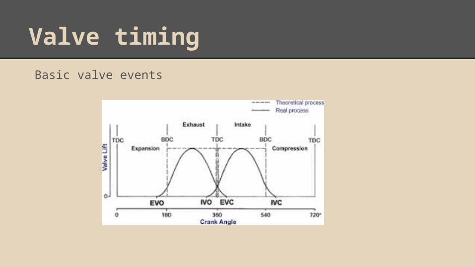
Valve timingBasic valve events

Valve timing
Late Intake valve closingHold intake valve open longer than normalValve closes in the compression strokePiston pushes air from the cylinder back into the intake manifold
i.e. reducing the displacement of the engineAir in the manifold is more pressurizedExpansion ratio is increased without increasing the compression
ratioReduction in pumping losses

Valve timingEarly intake valve closing:
Close intake valve mid-way through intake strokeLess air in the cylinder means less fuel is needed

Valve timingEarly intake valve opening
Intake Valve opens during exhaust stroke.Valve overlap is used to control the cylinder temperature. Some of the inert/combusted exhaust gas will back flow out of the cylinder, via the intake valve,
where it cools momentarily in the intake manifold. This inert gas then fills the cylinder in the subsequent intake stroke, which aids in controlling the
temperature of the cylinder and nitric oxide emissions. Improves volumetric efficiency because there is less exhaust gas to be expelled on the exhaust
stroke

Valve timingEarly/late exhaust valve closing
Exhaust Valve opens during power stroke allowing cylinder to be almost completely emptied of exhaust gas
Exhaust valve closes during exhaust stroke allowing more exhaust gas in the cylinder which increases fuel efficiency.
This allows for more efficient operation under all conditions.

Valve FlowThe most significant airflow restriction in an engine is the flow
through the intake and exhaust valvesMinimum cross sectional area occurs at the valves Must consider the pressure drop across the valves

Valve FlowIn idealized model of a poppet valve
Two minimum area possibilities Valve curtain area: A1 = πdℓValve seat area: A2= πd2/4
Low lifts- minimum area is valve curtain area
High lifts- minimum area is valve seat area

Valve FlowFlow coefficient
Ratio of effective flow area to a representative flow area Cl: Flow coefficient, used with valve seat area Cd:Discharge coefficient, used with valve curtain area
Representative flow area can be defined using the valve curtain area low lifts) or valve seat area (high lifts)Arep = ClAeff = Cl(πd2/4)Arep = CdAeff = Cdπdℓ

Valve FlowFigure shows experimental results of flow coefficient (Cl) vs lift
Arep = ClAeff = Cl(πd2/4)Effective flow area increases with lift
and flow coefficient increases with liftValve seat area (πd2/4) is constant Maximum flow coefficient seen

Valve FlowFigure shows experimental results of discharge coefficient (Cd) vs lift
Arep = CdAeff = CdπdℓValve curtain areaDischarge coefficient slightly
decreases with lift

Valve FlowMach Number defined as the ratio of the local flow velocity to the
speed of sound m = V/cIndicates if you are moving at supersonic speed

Valve FlowFigure shows experimental results of
volumetric efficiency vs intake valve Mach index
Can see that volumetric efficiency is greater at Mach index ≤ 0.6

Volumetric EfficiencyEngine intake system – the air filter, carburettor, and throttle plate (in a SI engine), intake manifold, intake port, intake valve – restricts the amount of air which an engine of given displacement volume (Vd ) can induct. The parameter used to measure the effectiveness of an engine’s induction process is the volumetric efficiency, ev .
ma = mass of air inducted into the cylinder per cycle ma = air induction rate into the cylinderN = engine speed, Ap = piston area, Sp = av. piston speedIf a,i = a,o (atmospheric air density) :- ev measures the pumping performance of the overall inlet system.If a,i = inlet manifold air density :- ev measures the pumping performance of the cylinder, inlet port and valve alone.

Factors effecting volumetric efficiencyThe volumetric efficiency depends on:
Fuel type, fuel/air ratio, fraction of fuel vaporized in the intake system, and fuel heat of vaporization
Mixture temperature as influenced by heat transferRatio of exhaust to inlet manifold pressuresCompression ratioEngine speedIntake and exhaust manifold and port designIntake and exhaust valve geometry, size, lift, and timings
Some of the variables are essentially quasi steady in nature (i.e. their impact is either independent of speed or can be described adequately in terms of mean engine speed), or dynamic in nature (i.e. their effects depend on the unsteady flow and pressure wave phenomena that accompany the time-varying nature of the gas exchange processes.)

Effect of IVO, IVC and engine speed in ev

Better Volumetric EfficiencyFor good volumetric efficiency, Z ≤ 0.6: the average gas speed through the inlet valve should be less than the sonic velocity, so that the intake flow is not choked.If Z = 0.6, average effective area of intake valves, Ai is
If Z = 0.6, average effective area of exhaust valves, Ae is
A smaller exhaust valve diameter and lift (Lv ∼Dv /4) can be used because of the speed of the sound is higher in the exhaust gases than in the inlet gas flow. Current practice dictates:

Current Valve TechnologyTypes of VVA methods
electrohydraulic electromechanicalCam-based actuators
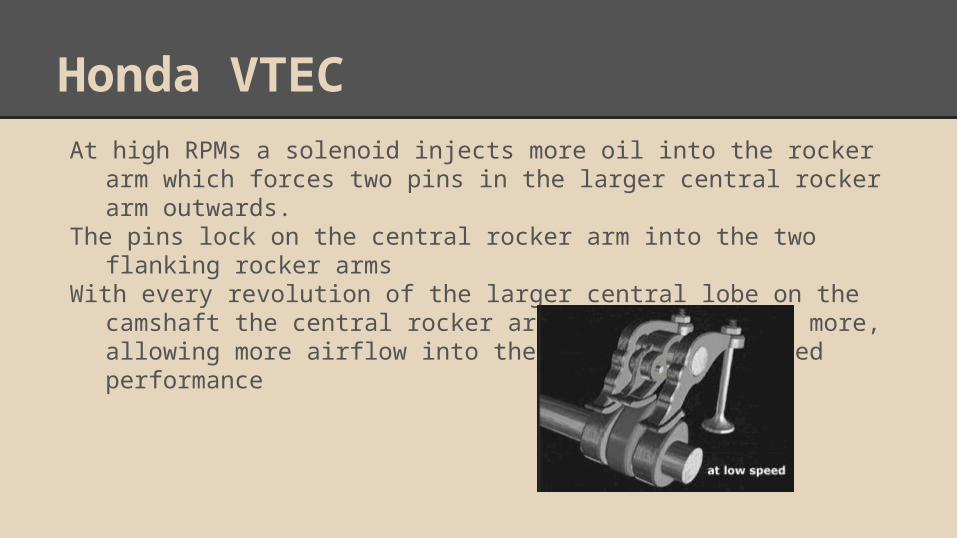
Honda VTECAt high RPMs a solenoid injects more oil into the rocker arm which
forces two pins in the larger central rocker arm outwards. The pins lock on the central rocker arm into the two flanking rocker
arms With every revolution of the larger central lobe on the camshaft the
central rocker arm opens the valves more, allowing more airflow into the engine for enhanced performance

BMW ValvetronicCylinder heads with Valvetronic use an extra set of rocker arms, called intermediate arms (lift scaler), positioned between the
valve stem and the camshaft. These intermediate arms are able to pivot on a central point, by means of an extra, electronically actuated camshaft. This movement alone, without any movement of the intake camshaft, can vary the intake valves' lift from fully open, or maximum power, to almost closed, or idle.
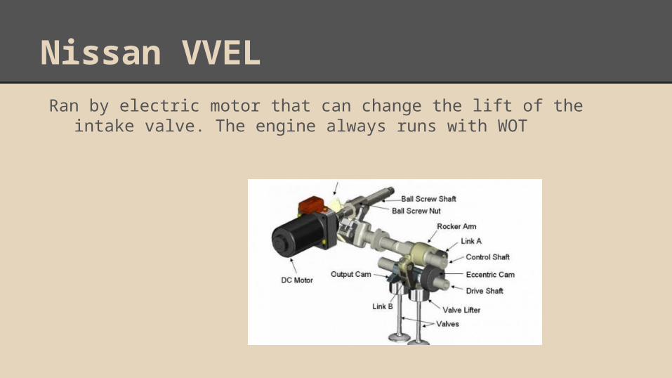
Nissan VVELRan by electric motor that can change the lift of the intake valve.
The engine always runs with WOT

Mercedes Benz CamtronicThe system consists of a camshaft that splits in two, plus a centrally mounted actuator with two vertical tappets. The actuator makes them drop into channels cut into the camshaft , which forces the cam sections to move laterally.

Fiat/Chrysler MultiairLaunched in 2009(Fiat) and 2011(Chysler)System aims to boost power, torque, and fuel efficiency of engineElectrohydraulic actuator controls pressure of fluid that fills
passageway that connects the intake valves and the camshaftWhen pressurized, transmits lift Can constantly regulate valve lift based on engine operation

Fiat/Chrysler MultiairThe system uses several strategies to optimize engine efficiency
LIVOEIVCMulti-lift Full- lift

Fiat/Chrysler MultiairLIVO- late intake valve opening
Used at engine start-up and idleResults in a higher speed air intakeBetter mixture formed Optimized combustion

Fiat/Chrysler MultiairEIVC- early intake valve closing
Used at engine partial load Stops undesired backflow into the intake manifold Traps maximum volume of air in cylinderIncreases volumetric efficiency Reduces pumping losses
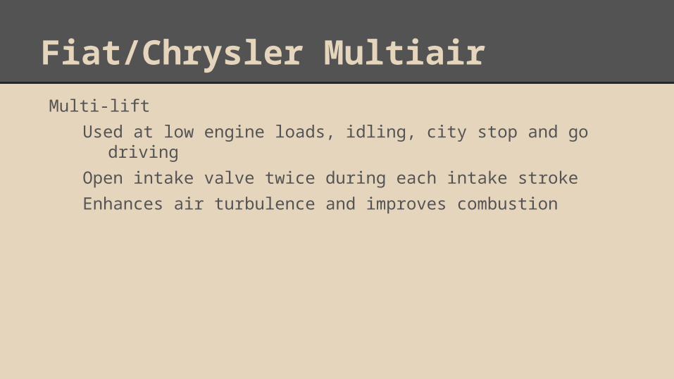
Fiat/Chrysler MultiairMulti-lift
Used at low engine loads, idling, city stop and go driving Open intake valve twice during each intake stroke Enhances air turbulence and improves combustion

Fiat/Chrysler MultiairFull Lift
Complete valve opening Used when full engine power is required

The Future of Valve Trains 1. electronic valve train engines(camless engines):
as the engine design is getting involved in the electromechanical systems and control, research is running these days toward fully controlled electromechanical valves, which will leads to a camless engines, and a better control in the valves positioning.

The Future of Valve Trainsadvantages: .better valve timing control.reduction of mechanical parts.reduction of friction caused by rocker arms,cam shaft,cam belt..ability to run engine on a higher speed.
disadvantages:. more complicated engine control system.. return spring characteristics limitations
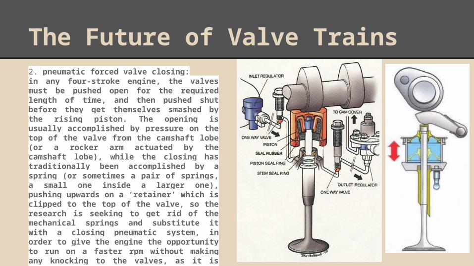
The Future of Valve Trains2. pneumatic forced valve closing:in any four-stroke engine, the valves must be pushed open for the required length of time, and then pushed shut before they get themselves smashed by the rising piston. The opening is usually accomplished by pressure on the top of the valve from the camshaft lobe (or a rocker arm actuated by the camshaft lobe), while the closing has traditionally been accomplished by a spring (or sometimes a pair of springs, a small one inside a larger one), pushing upwards on a ‘retainer’ which is clipped to the top of the valve, so the research is seeking to get rid of the mechanical springs and substitute it with a closing pneumatic system, in order to give the engine the opportunity to run on a faster rpm without making any knocking to the valves, as it is precisely controlled by the electro pneumatic system, and others using double rocker arms design to make he lobe open and close the valve..

Conclusion

Referenceshttp://www.mechadyne-int.com/vva-reference/intake-valve-closing-strategieshttp://www.mechadyne-int.com/vva-reference/papers/the-impact-of-variable-valve-actuation-on-engine-performance-and-emissions.pdfhttp://www.bmwforums.info/general-guides-and-how-to-s/4638-bmw-valvetronic.htmlhttp://www.me.sc.edu/researchhttp://www.google.com/patents/US8726861