Embed Size (px)
Citation preview

Dynamics of Viscous Fluid Flow in
Closed Pipe: Darcy-Weisbach equation for flow in pipes. Major and minor losses in pipe
lines.
Dr. Mohsin Siddique
Assistant Professor
1
FLUID MECHANICS

Steady Flow Through Pipes
2
� Laminar Flow:
flow in layers
Re<2000 (pipe flow)
� Turbulent Flow:
flow layers mixing with each other
Re >4000 (pipe flow)

Steady Flow Through Pipes
3
� Reynold’s Number(R or Re): It is ratio of inertial forces (Fi) to viscous forces (Fv) of flowing fluid
� For laminar flow: Re<=2000
� For transitional flow: 2000<Re<4000
� For Turbulent flow: Re>= 4000
. .
Re. .
. . .
.. .
Velocity VolumeMass Velocity
Fi Time Time
Fv Shear Stress Area Shear Stress Area
Q V AV V AV V VL VL
du VAA A
dy L
ρ
ρ ρ ρ ρ
τ µ υµ µ
= = =
= = = = =
Where ;V is avg. velocity of flow in pipeν is kinematic viscosityL is characteristic/representative linear dimension of pipe. It is diameter of pipe (circular conduits) or hydraulic radius (non-circular conduits).
νµ
ρ VDVDRe ==
Note: For non-circular section, we need to use hydraulic radius (Rh) instead of diameter (D) for the linear dimension (L).
Values of critical Reynolds no.

Steady Flow Through Pipes
4
� Hydraulic Radius (Rh) or Hydraulic Diameter: It is the ratio of area of flow to wetted perimeter of a channel or pipe
P
A
perimeterwetted
AreaRh ==
For Circular Pipe
( )( )
h
h
RD
D
D
D
P
AR
4
4
4/ 2
=
===π
π
For Rectangular pipe
DB
BD
P
ARh
2+==
B
D
Note: hydraulic Radius gives us indication for most economical section. More the Rh more economical will be the section.
ννh
h
VRVDR
4==
By replacing D with Rh, Reynolds’ number formulae can be used for non-circular sections as well.

Head Loss in Pipes
5
� Total Head Loss=Major Losses+ Minor Losses
� Major Loss: Due to pipe friction
� Minor Loss: Due to pipe fittings, bents and valves etc

Head Loss in Pipes due to Friction
6
The head loss due to friction in a given length of pipe is proportional to mean velocity of flow (V) as long as the flow in laminar. i.e.,
But with increasing velocity, as the flow become turbulent the head loss also varies and become proportion to Vn
Where n ranges from 1.75 to 2
Log-log plot for flow in uniform pipe (n=2.0 for rough wall pipe; n=1.75 for smooth wall pipe
VH f ∝
n
f VH ∝

Frictional Head Loss in Conduits of Constant
Cross-Section
7
� Consider stead flow in a conduit of uniform cross-section A. The pressure at section 1 & 2 are P1 & P2 respectively. The distance between the section is L. For equilibrium in stead flow,
∑ == 0maF
Figure: Schematic diagram of conduit
0sin 21 =−−− APPLWAP oτα
P= perimeter of conduit= Avg. shear stress
between pipe boundary and liquid
oτ
01221 =−
−−− PL
L
zzALAPAP oτγ
αsin12 =
−
L
zz

Frictional Head Loss in Conduits of Constant
cross-section
8
01221 =−
−−− PL
L
zzALAPAP oτγ
Dividing the equation by Aγ
( ) 01221 =−−−−
A
PLzz
PP o
γ
τ
γγ
fLo hhA
PLPz
Pz ===
+−
+
γ
τ
γγ2
21
1
Therefore, head loss due to friction hf can be written as
h
oof
R
L
A
PLh
γ
τ
γ
τ==
Lhg
vz
P
g
vz
P+++=++
22
2
22
2
2
11
1
γγ
Remember !! For pipe flow
For stead flow in pipe of uniform diameter v1=v2
LhzP
zP
=
+−
+ 2
21
1
γγ
This is general equation and can be applied to any shape conduit having either Laminar or turbulent flow.
P
ARh =Q

Determining Shear Stress
9
� For smooth-walled pipes/conduits, the average shear stress at the wall is
� Using Rayleigh's Theorem of dimensional analysis, the above relation can be written as;
� Rewriting above equation in terms of dimension (FLT), we get
( ),,,, VRf ho ρµτ =
( )
=
ncb
a
T
L
L
FT
L
FTLK
L
F4
2
22
( )ncba
ho VRk ... ρµτ =
LlengthR
L
Fareaforce
h
o
==
==2
/τ
( )22
4233
/.
////
/
−==
===
=
FTLmsN
LFTLaFLM
TLV
µ
ρ( ) ( ) ( ) ( )( )ncbaTLLFTFTLLKFL /4222 −−− =

Determining Shear Stress
10
� According to dimensional homogeneity, the dimension must be equal on either side of the equation, i.e.,
( ) ( ) ( ) ( )( )ncbaTLLFTFTLLKFL /4222 −−− =
)(20:
)(422:
)(1:
iiincbT
iincbaL
icbF
→−+=
→+−−=−
→+=Solving three equations, we get
1;2;2 −=−=−= ncnbna
� Substituting values back in above equation
( ) ( ) 2
2
122...... V
VRkVRkVRk
n
hnnnn
h
ncba
ho ρµ
ρρµρµτ
−
−−−
===
( ) 22VRk
n
eo ρτ−
=
� Setting = we get
2
2V
C fo ρτ = Where, Cf is coefficient of friction
( ) 2−n
eRk 2/fC

Determining Shear Stress
11
� Now substituting the equation of avg. shear stress in equation of head loss,
� For circular pipe flows, Rh=D/4
� Where, f is a friction factor. i.e.,
� The above equation is known as pipe friction equation and as Darcy-Weisbach equation.
� It is used for calculation of pipe-friction head loss for circular pipes flowing full (laminar or turbulent)
2/2VC fo ρτ =
h
of
R
Lh
γ
τ=
h
f
h
f
fgR
LVC
R
LVCh
22
22
==γ
ρ
g
V
D
Lf
g
V
D
LC
Dg
LVCh f
f
f22
442
4 222
===
( )Re4 fCf f ==

Friction Factor for Laminar and
Turbulent Flows in Circular Pipes
12
� Smooth and Rough Pipe
� Mathematically;
� Smooth Pipe
� Rough Pipe
� Transitional mode
Turbulent flow near boundary
=
=
v
e
δ
Roughness height
Thickness of viscous sub-layer
Smooth pipe
Rough pipe
f
D
fVv
Re
14.1414.14==
νδ
ve δ<
ve δ>
ve δ<
ve δ14>
vv e δδ 14≤≤

Friction Factor for Laminar and Turbulent Flows in
Circular Pipes
13
� For laminar flow
� For turbulent flow
Re
64=f2000Re <
51.2
Relog2
1 f
f=
9.6
Relog8.1
1=
f
25.0Re
316.0=f
7/1
max
=
or
y
u
u
Def /
7.3log2
1=
+−=
f
De
f Re
51.2
7.3
/log2
1
+
−=
Re
9.6
7.3
/log8.1
111.1
De
f
Colebrook Eq. for turbulent flow in all pipes
Halaand Eq. For turbulent flow in all pipes
Von-karman Eq. for fully rough flow
Blacius Eq. for smooth pipe flow
Seventh-root law
510Re3000 ≤≤
From Nikuradse experiments
Colebrook Eq. for smooth pipe flow
for smooth pipe flow
4000Re >

Friction Factor for Laminar and Turbulent Flows
in Circular Pipes
14
� The Moody chart or Moody diagram is a graph in non-dimensional form that relates the Darcy-Weisbach friction factor, Reynoldsnumber and relative roughness for fully developed flow in a circular pipe.
� The Moody chart is universally valid for all steady, fully developed,incompressible pipe flows.

Friction Factor for Laminar and Turbulent Flows
in Circular Pipes
15
� For laminar flow For non-laminar flow
eRf
64=
+−=
f
De
f Re
51.2
7.3
/log2
1 Colebrook eq.

Friction Factor for Laminar and
Turbulent Flows in Circular Pipes
16
� The friction factor can be determined by its Reynolds number (Re) and the Relative roughness (e/D) of the Pipe.( where: e = absolute roughness and D = diameter of pipe)

17

Problem Types
18
� Type 1: Determine f and hf,
� Type 2: Determine Q
� Type 3: Determine D

Problem
19
� Find friction factor for the following pipe
� e=0.002 ft
� D=1ft
� Kinematic Viscosity, ν=14.1x10⁻⁶ft2/s
� Velocity of flow, V=0.141ft/s
� Solution:
� e/D=0.002/1=0.002
� R=VD/ ν =1x0.141/(14.1x10-6)=10000
� From Moody’s Diagram; f=0.034___________
Re
51.2
7.3
/log2
1
=
+−=
f
f
De
f

Problem-Type 1
20
� Pipe dia= 3 inch & L=100m
� Re=50,000 ʋ=1.059x10⁻⁵ft2/s
� (a): Laminar flow:
� f=64/Re=64/50,000=0.00128
ftgD
fLVH Lf 0357.0
)12/3)(2.32(2
)12.2)(100(00128.0
2
22
===
sftVVVD
/12.210059.1
)12/3(50000Re
5=⇒
×=⇒=
−ν

Problem-Type 1
21
� Pipe dia= 3 inch & L=100m
� Re=50,000 ʋ=1.059x10⁻⁵ft2/s
� (b): Turbulent flow in smooth pipe: i.e.: e=0
0209.0
50000
51.2
7.3
0log2
Re
51.2
7.3
/log2
1
=
+−=
+−=
f
ff
De
f
ftgD
fLVH Lf 582.0
)12/3)(2.32(2
)12.2)(100(0209.0
2
22
===

Problem-Type 1
22
� Pipe dia= 3 inch & L=100m
� Re=50,000 ʋ=1.059x10⁻⁵ft2/s
� (c): Turbulent flow in rough pipe: i.e.: e/D=0.05
0720.0
50000
51.2
7.3
05.0log2
Re
51.2
7.3
/log2
1
=
+−=
+−=
f
ff
De
f
ftgD
fLVH Lf 01.2
)12/3)(2.32(2
)12.2)(100(0720.0
2
22
===

Problem-Type 1
23
hL=?
memDmL 0005.0;25.0;1000 ===
smsmQ /10306.1;/051.0 263 −×== ν
( ) ( )002.025.0/0005.0/
10210306.1/25.0039.1/ 56
==
×=××== −
De
VDR ν
0.0245f
Diagram sMoody' From
=
mgD
fLVhL 39.5
2
2
==
smAQV /039.1/ ==Q

Problem-Type 2
24
gDfLVhL 2/2=

Problem-Type 2
25
� For laminar flow For non-laminar flow
eRf
64=
+−=
f
De
f Re
51.2
7.3
/log2
1 Colebrook eq.

Problem-Type 3
26

Problem
27
gD
flVh
f
De
f
Lf2
Re
51.2
7.3
/log2
1
2
=
+−=

Problem
28

Problem
29

MINOR LOSSES
30
� Each type of loss can be quantified using a loss coefficient (K). Losses are proportional to velocity of flow and geometry of device.
� Where, Hm is minor loss and K is minor loss coefficient. The value of K is typically provided for various types/devices
� NOTE: If L > 1000D minor losses become significantly less than that of major losses and hence can be neglected.
g
VKHm
2
2
=

Minor Losses
31
� These can be categorized as
� 1. Head loss due to contraction in pipe
� 1.1 Sudden Contraction
� 1.2 Gradual Contraction
� 2. Entrance loss
� 3. Head loss due to enlargement of pipe
� 3.1 Sudden Enlargement
� 3.2 Gradual Enlargement
� 4. Exit loss
� 5. Head loss due to pipe fittings
� 6. Head loss due to bends and elbows

Minor Losses
32
� Head loss due to contraction of pipe (Sudden contraction)
� A sudden contraction (Figure) in pipe usually causes a marked drop in pressure in the pipe because of both the increase in velocity and the loss of energy of turbulence.
g
VKH cm
2
2
2=
Head loss due to sudden contraction is
Where, kc is sudden contraction coefficient and it value depends up ratio of D2/D1 and velocity (V2) in smaller pipe

Minor Losses
33
� Head loss due to enlargement of pipe (Gradual Contraction)
� Head loss from pipe contraction may be greatly reduced by introducing a gradual pipe transition known as a confusor as shown Figure.
g
VKH cm
2'
2
2=
Head loss due to gradual contraction is
Where, kc’ is gradual contraction
coefficient and it value depends up ratio of D2/D1 and velocity (V2) in smaller pipe

Minor Losses
34
� Entrance loss
� The general equation for an entrance head loss is also expressed in terms of velocity head of the pipe:
� The approximate values for the entrance loss coefficient (Ke) for different entrance conditions are given below
g
VKH em
2
2
=

Minor Losses
35
� head loss due to enlargement of pipe (Sudden Enlargement)
� The behavior of the energy grade line and the hydraulic grade line in the vicinity of a sudden pipe expansion is shown in Figure
The magnitude of the head loss may be expressed as
( )g
VVHm
2
2
21 −=
Minor Losses
36
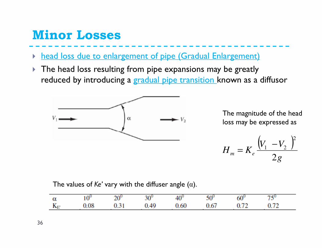
� head loss due to enlargement of pipe (Gradual Enlargement)
� The head loss resulting from pipe expansions may be greatly reduced by introducing a gradual pipe transition known as a diffusor
The magnitude of the head loss may be expressed as
( )g
VVKH em
2
2
21 −=
The values of Ke’ vary with the diffuser angle (α).

Minor Losses
37
� Exit Loss
� A submerged pipe discharging into a large reservoir (Figure ) is a special case of head loss from expansion.
( )g
VKH dm
2
2
=
Exit (discharge) head loss is expressed as
where the exit (discharge) loss coefficient Kd=1.0.

Minor Losses
38
� Head loss due to fittings valves
� Fittings are installed in pipelines to control flow. As with other losses in pipes, the head loss through fittings may also be expressed in terms of velocity head in the pipe:
g
VKH fm
2
2
=

Minor Losses
39
� Head loss due to bends
� The head loss produced at a bend was found to be dependent of the ratio the radius of curvature of the bend (R) to the diameter of the pipe (D). The loss of head due to a bend may be expressed in terms of the velocity head as
� For smooth pipe bend of 900, the values of Kb for various values of R/D are listed in following table.
g
VKH bm
2
2
=

Minor Losses
40

Numerical Problems
41

Numerical Problems
42

Thank you
� Questions….
� Feel free to contact:
43