Embed Size (px)
Citation preview

A MINOR PROJECT REPORT ON
FABRICATION OF AN AUDIO AMPLIFIER USING IC-LM386
SUBMITTED IN PARTIAL FULFILLMENT OF THE REQUIREMENTS FOR THE AWARD OF THE DEGREE OF
BACHELOR OF TECHNOLOGY
DEPARTMENT OF ELECTRICAL ENGINEERING
DELHI TECHNOLOGICAL UNIVERSITY,
Submitted By: Guided By :
MANISH KUMAR (2012/EE/076) N.K. BHAGAT
KAPIL TAPSI (2012/EE/066) Associate Professor
(Delhi Technological University)
CERTIFICATE
This is to certify that this project report entitled “FABRICATION OF AN AUDIO AMPLIFIER
USING IC-LM386” by :
MANISH KUMAR (2012/EE/076)
KAPIL TAPSI (2012/EE/066)
submitted in partial fulfillment of the requirements for the award of B.Tech
degree in Electrical Engineering of the Delhi Technical University, New Delhi,
during the academic year 2014-15 is a bonafide record of work carried out
under my guidance and supervision.
N.K. Bhagat
Associate Professor,
Deptt. of Electrical Engineering,
Delhi Technological University, New Delhi

ACKNOWLEDGEMENT
It is our honor and privilege to have been B. Tech. Students under the guidance of
Dr. N.K. Bhagat whose analytical abilities and personal touch have prompted us
to express deep sense of gratitude for him. In addition to being a formal guide his
sympathetic and practical approach towards any issue has really inspired us a lot.
We are thankful to him for his constant guidance in research or any other
personal matter during the entire course of this study.
We would like to express our gratitude to the management of DTU for providing
us a conductive work atmosphere. We would like to extend our gratitude to Head
of Department and all faculty of Electrical Department of DTU for their kind
support and guidance.
MANISH KUMAR (2K12/EE/076)
KAPIL TAPSI (2K12/EE/066)

INDEX
1. ABSTRACT
2. INTRODUCTION
3. COMPONENT REQUIRED
4. CIRCUIT DIAGRAM
5. WORKING
6. COMPONENT DETAILS
6.1 I.C. LM386
6.2 PCB Board Universal – Perforated 3x4” inches
6.3 Capacitor’s
6.4 Resistor’s
6.5 Potentiometer (10 k)
6.6 Battery (9V, Zinc Chloride)
6.7 Speaker
6.8 LED (Light Emitting Diode)
7. FINAL PRODUCT
8. APPLICATION’S
9. ADVANTAGES / DISADVANTAGES
10. CONCLUSION
11. REFERENCE’S

ABSTRACT
The purpose of this project is to introduce the audio amplifiers using the popular audio amplifier integrated circuit (IC) LM386 and then measuring the amplifier performance, including its gain. The LM386 is a power amplifier designed for use in low voltage consumer applications. The gain is internally set to 20 to keep external part count low, but the addition of an external resistor and capacitor between pins 1 and 8 will increase the gain to any value up to 200. The inputs are ground referenced while the output is automatically biased to one half the supply voltage. The quiescent power drain is only 24 milliwatts when operating from a 6 volt supply, making the LM386 ideal for battery operation
INTRODUCTION
The LM386 IC is a low voltage audio power amplifier with a default voltage gain
of 20, which can however be increased to any value between 20 and 200 by simply
placing an external series RC circuit between pins 1 and 8.So pin 1 and 8 are gain
controlling pins. In the amplifier circuit, the output AC power is clearly larger than
the input AC power reflecting the voltage, and thus power, gain. The increase in
AC power in going from the input terminals of the amplifier to the output terminals
are provided by the DC voltage source biasing the circuit. In the case of the
LM386 IC, the operating DC power source must have a voltage between 4V and
12V and supply a current of 100 mA. So I provide it a power supply of 9 volt and
220 mA. These values of DC voltage and current are readily provided by a battery
so that an audio amplifier based on the LM386 IC is very much amenable to
battery operation.

COMPONENTS REQUIRED
PRODUCT’S MODEL
0.047 uf Capacitor CC-0.04uf
0.01 uf Capacitor CC-103
100 uf / 25V Radial Electrolytic
Capacitor
CE-100u25
10 uf / 50V Radial Electrolytic
Capacitor
CE-10u50
10 uf / 63V Radial Electrolytic
Capacitor
CE-10u63
220 uf / 25V Radial Electrolytic
Capacitor
CE-220u25
LM386-Low Voltage Amplifier ICPA_LM386
Green 5mm LED Diffused LED-5GD
10 K Potentiometer MP-POT-10K-3590
Toggle Switch MSW-DPDTT24

PRODUCT’S MODEL
9V Battery Snap Connector PB-9Vsc
9V Battery Zinc Chloride PB-9vZC
10 ohm ,1/4 Watt Resistor RQ-10
Speaker – 8 ohm / 0.5 W (small
speaker)
SB_S8_05W
Hookup Wires – 22Gwg Solid TABB_HW22G
PCB Board Universal –
Perforated 3x4” inches
Tae-PCB3x4_p

CIRCUIT DIAGRAM
LM386 Connection Diagrams
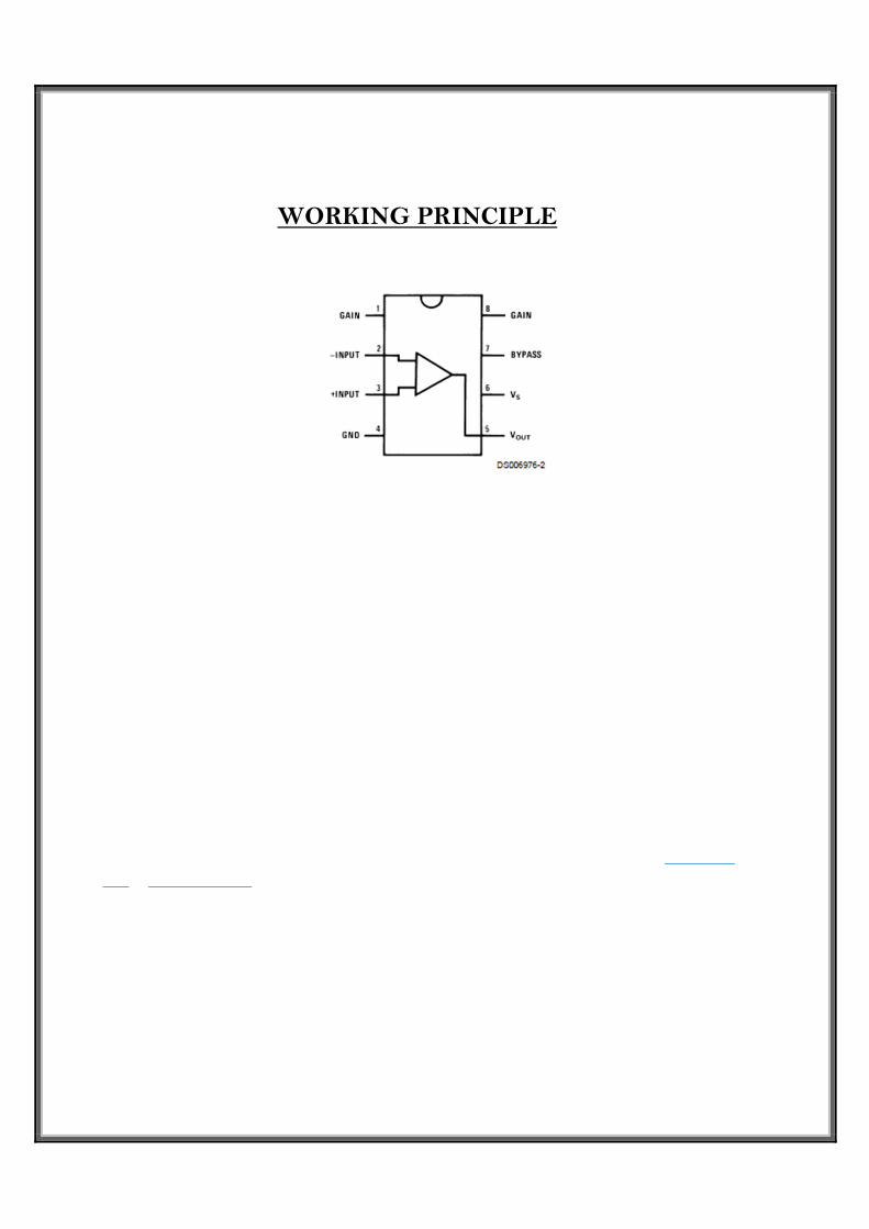
WORKING PRINCIPLE
Let’s have a look at the pin out and see what is the role of each part in the schematic above.
Pins 1 and 8 control gain. When not connected (NC), the amplifier gain is 20. Adding a 10uF capacitor between them gives a gain of 200. Intermediate values are also possible, as described in the datasheet.
Pins 2 is the negative input – GND in our case.
Pin 3 is the positive input – i.e. the actual signal to be amplified. There is a 10K potentiometer before it,
which adjusts the input signal level, acting as a volume control.
Pins 4 (GND) and 6 (Vs) provide the supply voltage for the amplification. For this setup a 4x AA NiMh battery pack is used, which provides ~5V.
Pin 5 is the output. It is biased to 1/2 of the supply voltage Vs. In simple terms, this means that the signal there has two components: An AC component, which is the amplified input signal, plus a DC component of 1/2 Vs = 2.5V. This biased voltage cannot be fed directly to a speaker, but is exactly what we need for a μC sound sensor. The 250uF electrolytic capacitor filters out the DC component and the remaining AC goes to the speaker.
The 0.05uF capacitor and 10 ohm resistor pair from pin 5 to ground turns out to be called a“Boucherot cell” or “Zobel Network” and is used to prevent high frequency oscillations. Pin 7 is just named bypass, but the datasheet does not provide any further detail on it or its usage.

COMPONENTS DETAIL IC LM386 :
The LM386 is a power amplifier IC designed for use in low voltage consumer
applications. The gain is internally set to 20 to keep external part count low, but the
addition of an external resistor and capacitor between pins 1 and 8 will increase the
gain to any value from 20 to 200.So pin 1 and 8 are gain controlling pins. I give
input to pin no 3(positive) so out is non-inverting. If I give input to pin no 2 the
output will be out of phase.

PCB (PERFORATED BOARD)
Perfboard is a material for prototyping electronic circuits also called (DOT PCB). It is a thin, rigid sheet with holes pre-drilled at standard intervals across a grid, usually a square grid of 2.54 mm (0.1 in) spacing. These holes are ringed by round or square copper pads. Inexpensive perfboard may have pads on only one side of the board, while better quality perfboard can have pads on both sides (plate-through holes). Since each pad is electrically isolated, the builder makes all connections with either wire wrap or miniature point to point wiring techniques. Discrete components are soldered to the prototype board such as resistors, capacitors, and integrated circuits. The substrate is typically made of paper laminated with phenolic resin (such as FR-2) or a fiberglass-reinforced epoxy laminate.

Capacitor:
Radial electrolytic capacitors Ceramic capacitors
A capacitor is a passive two-terminal electrical component used to store energy
electrostatically in an electric field .When there is a potential difference across the
conductors, an electric field develops across the dielectric, causing positive charge
to collect on one plate and negative charge on the other plate. Energy is stored in
the electrostatic field. An ideal capacitor is characterized by a single constant
value, capacitance. This is the ratio of the electric charge on each conductor to
the potential difference between them. The SI unit of capacitance is the farad,
which is equal to one coulomb per volt. An ideal capacitor is wholly characterized
by a constant capacitance C, defined as the ratio of charge ±Q on each conductor
to the voltage V between them

Resistor:
Resistors are the most common passive electronic component (one that does not require power to operate). They are used to control voltages and currents. While a resistor is a very basic component, there are many ways to manufacture them. Each style has its own characteristics that make it desirable in certain types of applications. Choosing the right type of resistor is important to making high-performance or precision circuits work well. This bonus chapter covers the resistor types and helps with picking the right one for your project .All resistors are basically just a piece of conducting material with a specific value of resistance. For that piece of conducting material to be made into a practical resistor, a pair of electrodes and leads are attached so current can flow. The resistor is then coated with an insulating material to protect the conducting material from the surrounding environment and vice versa. There are several different resistor construction methods and body styles (or packages) that are designed for a certain range of applied voltage, power dissipation, or other considerations. The construction of the resistor can affect its performance at high frequencies where it may act like a small inductor or capacitor has been added, called parasitic inductance or capacitance.