Embed Size (px)
Citation preview

EOR (Enhance Oil Recovery): Feasibility-Implementation-Evaluation
Production Geologist (Development Geologist)
Practical use and Reference

EOR ACTIVITY Feasibility Study
Screening of EOR Method
Laboratory Study
Review and Update GGRPFE/GGRP
Process facility study
Full Scale Economic Evaluation
Feasibility Study Result
Implementation Trial/ Pilot EOR
Implementation Trial/ Pilot EOR Proposal
Preparation Trial/ Pilot EOR
Execution Trial/ Pilot EOR
Data gathering, Monitoring & Surveillance
Evaluation Trial/ Pilot EOR
Production gain method
Operation technical method
Reporting of Implementation Trial/ Pilot EOR

Feasibility Study
The purposes of EOR (Enhance Oil Recovery) Feasibility Study is tounderstand fully of the fields in the first place, whether the fieldseconomic/ feasible to be developed by EOR method implementation.
The feasibility study consist of screening of EOR method, LaboratoryStudy, Review and Update GGRPFE, Process facility study, then FullScale Economic Evaluation. If categorized feasible, then need to betested by field trial / pilot about 1-2 pattern

Screening of EOR (Enhance Oil Recovery) Method should conduct eachlayer / zone due to may have different reservoir characteristic.Reservoir parameters are necessary for EOR Screening , consist of:
1. Oil API gravity
2. Oil viscosity
3. Rocks Porosity
4. Oil Saturation
5. Lithology
6. Permeability
7. Reservoir Depth & temperature
8. Hydrocarbon composition etc.
Screening of EOR Method

Screening of EOR Method
There are 16 type of EOR (Enhance Oil Recovery) method (Aladasanifrn.2010) such: Miscible CO2, Miscible Hydrocarbon, Miscible WAG,Miscible Nitrogen, immiscible Nitrogen, immiscible CO2, immiscibleHydrocarbon, immiscible Hydrocarbon + WAG, Polymer, Alkaline-Surfactan-polymer (ASP), Surfactant +P/A, Combustion, Hot water,Steam, Surface mining, microbial.

Laboratory test consist of fluids characteristic, native core/ Rocks, and media EOR as follows:
1. Rocks / native core; routine core & SCAL, Porosity and permeability, SEM, XRD, Rocks chemical analysis, rocks wettability.
2. Water Formation and injection test: pH, salinity, density, viscosity, complete water analysis, bacterial, scaling tendency
3. Oil characteristic: density, viscosity, melting point, acid number, composition, oil type
4. Chemical test: ASP if necessary add cosurfactan & solvent where each can mixed/ formulated as flow diagram (next Slide).
Laboratory Study

Flow Diagram
Formulated/ Selection
of surfactant
If all surfactant parametersfulfilled , then may conductanother test adjusted as coreflood simulation test. Need toconsider synthetic core whethernative core very limited.
Sometime surfactant liquid needto take compatibility test,behavior phase test, IFT stabilitytest, Filtration test, andadsorption test.

Polymer test
Polymer evaluation purposes is toget polymer material that mayimprove water viscosity inreservoir, therefore mobility oil-water ratio smaller than 1 (one).
See The flow diagram of polymerstudy
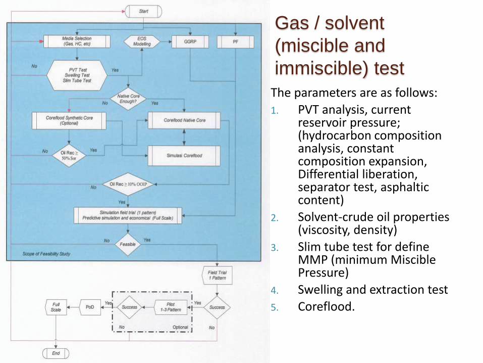
Gas / solvent
(miscible and
immiscible) test
The parameters are as follows:
1. PVT analysis, current reservoir pressure; (hydrocarbon composition analysis, constant composition expansion, Differential liberation, separator test, asphaltic content)
2. Solvent-crude oil properties (viscosity, density)
3. Slim tube test for define MMP (minimum Miscible Pressure)
4. Swelling and extraction test
5. Coreflood.

Thermal media
testThermal method use heat energy as themedia, with assume that increasing thetemperature made oil viscosity goes down inreservoir, the media may steam, hot water,etc. The parameters are as follows:
1. PVT analysis, current reservoirpressure; (hydrocarbon compositionanalysis, constant compositionexpansion, Differential liberation,separator test)
2. Viscosity and density of fluid andthermal media
3. Rocks structure break @ temp.
4. Oil swelling due to thermal expansion
5. Heat capacity from rocks and reservoirfluid
6. Bottom water
7. Loss heat/ thermal
8. Coreflood (recovery test)

Another media
testAnother media method such MEOR (Microbialenhance oil recovery), its amount of microbe inreservoir where the population improved bygiving enough nutrition in reservoir condition.Microbe activity to be expected give surfactanteffect and also break HC chain and decrease theoil viscosity. The parameters are as follows:
1. Define the amount and microbe type
2. Selection/ formulation of nutrition toimprove the acceleration of microbegrowth @ (time function, nutritionconcentrate and reservoir temp.)
3. Filtration test @ microbe and nutritionconcentrate
4. Viscosity test and reservoir density fluid @incubation time
5. IFT test @ reservoir temp.
6. Imbibition as time function

Review and Update
GGRPFE

Review and Update GGRPFEThe main purposes of reservoir simulation are to make oilproduction forecast in field scale using chosen EORmethod and input data of laboratory test also updateG&G model. Then evaluate the necessity of productionand injection facility also the economic as the finalfeasibility study. If the field feasible, the continue to fieldtrial / pilot.
The field trial / pilot is better use pattern that has goodconnectivity between injection and production wells,good oil saturation, area pattern about 4-5 acre with 4-5spot, and distance injection-production wells max 100mas for surveillance will be fast.
Input data for EOR reservoir simulation consist of:
Static 3D model reservoir geology model (Porositydistribution, facies distribution, permeabilitydistribution)
Dynamic reservoir data (SCAL, PVT {Pb, Bob, Gassolution, Specific gas}, and Production data withpressure)
Laboratory study as EOR type e.g. ASP
Legend:
Injector
Producer
Monitor
confining

Injection facility studyMaking sure the water fulfill criteria and compatible with reservoir thereforeneed treatments. It has to through filtering, free oil & plug from microbe, watersoftener, neutral pH. The water composition must adjusted with conditionfrom laboratory test therefore the chemical has property as formulated.
Injection facility that necessary for each EOR method can be explain as follows:
1. Chemical method (ASP), the facility consist of: Tank(for chemical), mixer tank (main solvent), mixer tank ( for solvent as formulated lab.), filter, storage tank/ surge tank, transfer pump & pipe between equipment, injection pump to the well.
2. Gas/ solvent method, the facility consist of: separator (for absorption, distillation, gas dryer etc.), Surge tank, pipe for surface facility to well head and compressors (transfer & injection.)
3. Thermal method, the facility consist of: heat exchanger and boiler, water treatment, pipe (with insulation for steam transport), and pump.
4. Microbe method, the facility consist of: mixer tank (nutrition), Pipe and transfer pump. Injection pump.

Production Facility study
Production test in Collector station, should separate
with existing facility therefore the measurement will
more accurate and the handling will be easier
particularly with emulsion.

Economic evaluation comprises: ROI (Return on
investment), NPV (Net present value), and IRR
(Internal rate of return) as company standard.
Economic sensitivity need to be done for giving the
success criteria picture of field trial/ pilot. If the
evaluation result assume gain profit, then it can
recommend for field trial/pilot implementation.
Full Scale Economic Evaluation

Feasibility study result that can be used as guidance field trial/
pilot implementation consist of:
1. Quantity and quality water injection data and water
process that needed as field necessity
2. Quantity, quality, and operation condition EOR media that
needed (such chemical material: IFT, FR, concentration
etc.)
3. The best Pattern location include area and pattern type
that recommended
4. Surface facility that needed
5. Oil and gas reserves on pilot scale and full field scale
6. Forecast production for pilot scale
Feasibility Study Result

Implementation Trial/ Pilot EOR
Implementation Trial/ Pilot EOR is proving or confirmation step
from feasibility study. According to the result of EOR feasibility
study, the party have to prepare work plan and budget also
activity step that necessary as regulator guidance, and then
after get approval from any related parties the Implementation
Trial/ Pilot EOR need to be prepared (Subsurface, surface and
procurement to monitoring & surveillance).
The next Implementation Trial/ Pilot EOR step is Execution,
consist of: EPCI and production wells, injector, also monitoring
as necessary. Mitigation risk also needed for avoid any
unwanted disturbance or other factor may delay the
Implementation Trial/ Pilot EOR project.

The proposal usually consist of:
1. Candidate Trial/ Pilot EOR area process selection
2. Reservoir performance (Primary and secondary recovery)
3. Screening process EOR method
4. Uncertainty factor and GGRP model
5. Additional gain reserve forecast and production profile full field
6. Full field EOR economic
7. Existing operational condition (facility, wells etc.)
8. Simulation pattern design for pilot and full field EOR
9. Trial/ Pilot EOR plan (Purposes, pattern type , wells & facility Trial/ Pilot EOR necessity, injectant EOR defined, parameter EOR, baseline, monitoring success criteria, schedule, budget etc.)
10. Project schedule for full scale EOR usually in POD or POFD
Implementation Trial/ Pilot EOR Proposal

The Preparation Trial/ Pilot EOR usually consist of:
1. Team executor (total support from top management, operational decision making, independent in handling area trial/ pilot, dedicated and experienced etc.)
2. Budgeting (allocation particular budget for Trial/ Pilot EOR obvious)
3. Procurements of EOR bulk material (volume nd specification, estimation budget)
4. Surface facility (FEED{Front end engineering design} for Trial/ Pilot EOR, EPCI (Engineering Procurement Installation) phase
5. Make sure laboratory Available for monitoring & surveillance
Preparation Trial/ Pilot EOR

Execution Trial/ Pilot EOR comprises Monitoring & surveillance program andQuality assurance QA / Quality control QC. And the Monitoring & surveillanceprogram consist of:
1. Monitoring production wells (Daily-production test Gross/net, WC.Weekly-WHP{well head pressure}, Dynamic fluid level, sonolog/dynagraph. Monthly-SBHP{static bottom hole pressure})
2. Monitoring Injection well (daily-rate injection, injectant concentration,BHP. Weekly- WHP. Oxygen activate logging min twice in Pilot. Fall off testas necessary)
3. Monitoring EOR Plant (chemical/ Polymer/ Miscible and immiscible gasetc.)
4. Surveillance program (tracer test, pulse test, pressure build up, and skinfactor min twice in Pilot time. Pattern balancing, fluid drift, patternrealignment for gaining comprehensive data in building confident levelfrom field trial/ pilot result)
Execution Trial/ Pilot EOR

Execution Trial/ Pilot EOR
Quality assurance QA / Quality control QC depends on Injectant such:
1. Chemical: chemical material must calculate bulk volume asrequested, then sampling with randomly, after that conductlaboratory test to know the quality as specification, and finallyput in the right place.
2. Polymer: Same as chemical step
3. Miscible and immiscible gas (solvent): Same as chemical step butusually put in compressor
4. Thermal: Same as chemical step but different supportingequipment
5. Another (microbe): Same as chemical step

Data gathering, Monitoring & Surveillance consist of:
1. Performance of mixing plant, WTP, and WIP as target
2. Quality from EOR parameter (SI, IFT, pH etc.)
3. Analyze Injection Well performance, such: Hall-Plot analysis
4. Process improvement from monitor Area(Production wells Injections and Surface facility) from evaluation result.
5. Plotting daily actual oil production to simulation result.
Data gathering, Monitoring & Surveillance

Evaluation Trial/ Pilot EOR
The success evaluation field trial/ pilot EOR is based on two method they are Production gain method & Operation technical method. The Production gain method conducted with plotting production realization as long as field trial/ pilot using daily basis and compare it with forecast field trial/ pilot that from simulation result. Success criteria in Production gain method based on economic sensitivity from feasibility study.
The Operation technical method conducted by using the scoring on influenced parameters.

Evaluation Trial/ Pilot EOR
The parameters success criteria of Operation technical method consist of:
1. Health, safety, security, & environment (HSSE)
2. Fluid handling & facilities performance
3. Monitoring & surveillance reliability
4. Production performance
5. Injectan performance
6. Operation reliability
7. Design matching (Laboratory, Reservoir simulation-forecast production, and production facilities)

Reporting of Implementation
Trial/ Pilot EORThe reporting of Implementation Trial/ Pilot EOR containing the documentation thatdescribe the process, performance results, prediction and actual comparison,recommendations and conclusions from all Implementation Trial/ Pilot EOR events. Thedocument comprises:
1. Summary data (Trial/ Pilot EOR Material, budget)
2. Recovery factor (Oil saturation before and after flooding such: coring, RST, CHFR, tracer test)
3. Production performance (Production profile Forecast vs actual, Rate production)
4. Injection Performance (Rate Injection, Pressure performance, Volume)
5. Operation Performance (Mixing, QA/QC, Injection, Production, Laboratory test)
6. Pressure Performance (Pressure distribution, anomaly, down time)
7. Update/ Fixing chance (EOR quality material, Slug design, operation improvement, Facility design, well design, pattern design, etc.)
8. Success evaluation
9. Recommendation and future plan (full scale economic based on implementation Trial/ Pilot EOR with comparing sensitivity on feasibility study result, justification for full scale EOR)

Screening EOR Method with nitrogen and flue gas
Injection (according to Taber and friends - 1997)

Screening EOR Method with miscible hydrocarbon
injection (according to Taber and friends - 1997)

Screening EOR Method with CO2 Injection (according
to Taber and friends - 1997)

Screening EOR Method with Polymer, ASP Injection
(according to Taber and friends - 1997)

Screening EOR Method with Polymer Injection
(according to Taber and friends - 1997)

Screening EOR Method with Insitu combustion
Injection (according to Taber and friends - 1997)

Screening EOR Method with Steam Injection
(according to Taber and friends - 1997)

Screening EOR
Method (according to
Aladasani and friends -
2010)

area of zone :420.6 sq km oil-bearing area :3.8 sq km
geological reserves : million barrels The oil gravity :35-50°API
geological stratification; 14 small layers reservoir thickness :1-12m
reservoir depth:30-460m the average pressure coefficient :0.49 the
average porosity :0.29 the average permeability :122.7md
OMG regional geological characteristics
CASE: OMG Field in SE Asia

Because OMG oilfield rely on natural depletion long-term, recovery
degree is 20.65%, at present the Formation energy shortfall is serious, the
energy yield is low, it is necessary to combine the factors such as structure,
sandstone development condition, drilling horizon of the wells, the
condition of oil well output and so on to optimize well group in water
injection site testing to analyze the feasibility of waterflooding, which can
provide the basis for the field of large-scale water flooding adjustment
Test area selection and structural characteristics
CASE: OMG Field in SE Asia

Test area selection is mainly based on the following principles:
① located in the oil production center, closer to the terminal, convenient
for management, and convenient for tracking the effect;
② there is no floor production equipment on well site and it is
advantageous for the construction;
③ the connecting condition with oil well is relatively good;
④ has the water injection conditions;
⑤. Consider the utilization condition of 3 Wells which were drilled in 2016;
⑥. Select OM-1, OM-3, OM-5 layer to inject.
CASE: OMG Field in SE Asia

SB1 Qoi 50.3 bopd (?/?/???)
PU: 64bfpd/1.3 bopd/98%WC(Sep’1991)
Cum. 10.5MBO (Des’87-Sep’91)
STC Qoi 32.6 bopd (Okt’91) & 7.25 bopd (Jul’2005)
PU: 13bfpd/2.7bopd/79.5%WC(Jan’2010)
Cum. 37.6MBO (Des’87-Jan’2010)
TD =173m
TOC 131.5m
SB2 (OH) Qoi 38 bopd (Jul’1908)
Cum. 10.5MBO (Des’87-Sep’91)
STC Qoi 4.4bopd (Nov’1903)
PU: 2bfpd/1.7bopd/85%WC(Okt’2011)
Cum. 22.6MBO (Des’87-Okt’2011)
TD =236.5 m
OMG-107KB =93.2m
SqueezePropose
dOpen
Injection
OMG-104KB=73.1m 144m
OMG-158AKB =82.8m180m
STC Qoi 17.48bopd (Nov’1991)
PU: 11.8bfpd/1.1bopd/90.4%WC(Jul’2011)
Cum. 40.7MBO (Des’87-Des’2011)
TD =128 m
CASE: OMG Field in SE Asia

Injection - Production history, Oil reserve at Area Pilot & Forecast
Production Pilot
Distribution of injection wells
Injection - Production history
OMG-107
Oil reserve at Area Pilot
Forecast Production Pilot
CASE: OMG Field in SE Asia

Design basis: the reservoir engineering design of improving oil recovery
by water flooding in KM oilfield
Design principle: on the basis of reservoir engineering plan, combine
with the reservoir characteristics and oil field technological conditions,
chose the economic and practical production technology to ensure the
requirements of reservoir development; Pay attention to the whole
process of reservoir protection, environment protection and
construction safety during the oilfield development; Chose a complete
set of mature production technology in order to reduce investment and
operation cost and optimize machine mining equipment.
Production engineering
design
CASE: OMG Field in SE Asia

Injection process design
1. Water injection design Based on reservoir engineering design requirements, OMG107 Well injection
allocation 400 BBL/day, OMG 606 well injection allocation 600 BBL/day.
2. Water injection string design
Tubing: 2 7/8 "EUE tubing;General injection string: 2 7/8 "EUE tubing + bell guide;
Separate injection string: eccentric injection mandrel and constant pressure valve.
3. Wellhead selection
Design water injection wellhead pressure 10 MPa, and have test, blowout, wash well,
and other functions.
Lifting scheme design process
1. Lifting way choice
Choose lifting way follows the principle: the election rise way can ensure the
development plan forecast capacity index, at the same time consider lifting way of
reliability, economy.
At present more mature lifting method for pumping unit, and its advantages for fluid
volume adaptation range, and large scope, matching technology is mature, workers
skilled operation. Therefore determination by way of pumping unit lifting.
CASE: OMG Field in SE Asia

2. Pumping unit, sucker rod, pump
(1) Determine the pump depth
Under the pump depth is determined according to the single well perforation, and
ensure reasonable flowing pressure. This plan according to the geological
requirements, depth of pump depth more than 20 m in the reservoir.
(2) Pump diameter
According to the geological forecast production, at 25% of the pump efficiency
calculation, considering water cut rising problem in the process of mining, selected
pump should be set aside room for maneuver. Choose pump is 50.8 mm in diameter.
(3) Sucker rod design
Oil well pump under different depth, stroke, Circulation per minute, pump diameter,
on the basis of equal strength principle, the use of software for dynamic simulation,
the calculation of the various parameters.
Selects the c-class 19 mm rod can meet the requirements.
(4) Lifting way model and power distribution equipment selection
Lifting mode choice models:
Underground pumping unit model mainly depends on the rod string and liquid
column load. When put into production early design utilization is 65% ~ 95%, can
press load torque utilization is 55% ~ 90% range to choose pumping unit.
CASE: OMG Field in SE Asia

Pumping
unit model
stroke Pump
diameter
Circulation
per minute
theoretical
displacement
pump efficiency
of 25% forecast output
(m) (mm) (1/min) (bbl/d) (bbl/d)
25-67-36 0.914
50.8
12 201.3 50.3
10 167.7 41.9
9 150.9 37.7
38.1
12 113.2 28.3
10 94.3 23.6
9 84.9 21.2
40-76-48 1.21
50.8
12 266.4 66.6
10 222 55.5
9 199.8 50.0
38.1
12 149.9 37.5
10 124.9 31.2
9 112.4 28.1
Estimation pump drainage quantity under 25% the pump efficiency CASE: OMG Field in SE Asia

Pumping unit modelrated torque
(KN.m)
rated load
(KN)
Max stroke
(m)
25-67-36 2.82 29.8 0.914
40-76-48 4.52 33.78 1.21
57-76-54 6.44 33.78 1.37
On the basis of pump diameter 50.8 mm,sucker rod 19 mm, 12 times/min calculation
pumping parameters calculation
Pumping
unit model
stroke Depth of
the pump
Calculating
the torque
Torque
utilization
Calculation of
maximum load
Utilization
rate of loadThe motor
(m) (m) (KN.m) (%) (KN) (%) (kw) (HP)
25-67-36 0.914 370 2.26 80.1 15.7 52.7 4.7 6.31
40-76-48 1.21 430 3.61 79.9 18.7 55.4 7.6 10.08
57-76-54 1.37 540 5.17 80.3 23.8 70.5 10.8 14.44
current model under the maximum depth of the pump
CASE: OMG Field in SE Asia

The choice of motor:
Motor selection to meet the installed power and under the premise of
stable operation, convenient for later production management.
(5) Wellhead design
Meet the admissions materials, pressure, casing connections, tubing
suspended load, operation convenient.
3. the tubing design
On the basis of joint connection strength, collapsing strength and internal
pressure strength requirement. Choose 2 7/8 "N80 EUE tubing.
CASE: OMG Field in SE Asia

NO. NAME Specification Unit Quantity
1 Pumping unit 40-76-48 set 7
2 Pumping unit 25-67-36 set 3
3 Electric motor 20HP set 7
4 Electric motor 10HP set 3
5 Christmas tree oil well set 10
6 Christmas tree injection well set 2
7 POLISHED ROD 1 1/8", 22 FT joint 10
8 Polished rod clamps 1 1/8" unit 10
9 POLISHED ROD coupling 1 1/8"-3/4" unit 10
10 SUCKER ROD 3/4"X 25 ft GRADE D CW, SR COUPLING m 2970
11 PONY ROD 3/4"X 4 FT, CW, SR COUPLING joint 20
12 PONY ROD 3/4"X 6 FT, CW, SR COUPLING joint 10
13 Sucker rod centralizer FGKC19-58WR unit 70
14 Oil pump RWMA 25×200×12ft set 10
15 Tubing 2 7/8 ", J55, 6.5 PPF, EU, R2 m 3680
16 Pup Joint of Tubing 2 7/8", 2ft joint 2
17 Pup Joint of Tubing 2 7/8", 6ft joint 1
18 Screen SG-1.5 joint 10
19 Plug 2 7/8"EU unit 10
The material list for petroleum engineering
CASE: OMG Field in SE Asia

Check
valve flow
gauge
gate
valve
gate
valve
flow
gauge
gate
valve
gate
valve
gate
valve
packer
air release
valve
wellheadair release valve
Ground seat union
Ground seat union
Connect to
tubing
Connect to
casing
oil layer oil layer
oil layer oil layer
CASE: OMG Field in SE Asia

Design basis: the reservoir and production engineering design of improving oil
recovery by water flooding in KM oilfield.
Design principles: strictly carrying out the relevant national laws, regulations and
the relevant national and industry standards and norms; To protect environment,
reduce pollution, oil, gas, water gathering and processing should satisfy the
standard of environmental protection, do not discharge oil, waste gas, waste water.
The ground engineering design
Oil gathering system
The production Wells located in OMG station, new production fluid on mechanical
production Wells are relying on the existing station remaining capable of handling.
According to the situation of oil collecting system has been built, this project adopts
the concentrated tank, multiwell concatenated set oil, oil transfer pump transmission
oil gathering process regularly. Total construction 10 wells, new oil pipes 1.48 km, 2
tank and 1 pump (Q = 120 BBL/h, h = 160 m; P = 40 HP)
CASE: OMG Field in SE Asia

Full Scale EOR Waterflooding
KM-001
KM-002KM-003
KM-004
KM-005AKM-005B
KM-006
KM-007
KM-008
KM-009
KM-010
KM-011
KM-012KM-013KM-014
KM-015
KM-016
KM-017
KM-018
KM-019
KM-020
KM-021
KM-022
KM-022/55J
KM-023
KM-023/38
KM-023/96
KM-024
KM-024/77
KM-025
KM-025/17J
KM-025/1E
KM-026
KM-027KM-028
KM-029
KM-030
KM-031
KM-032
KM-033
KM-034
KM-035
KM-036KM-037
KM-038
KM-039
KM-040
KM-041
KM-042
KM-043
KM-044
KM-045
KM-046
KM-047
KM-048
KM-049
KM-050
KM-051
KM-052
KM-053
KM-054
KM-055
KM-056
KM-057
KM-058
KM-059
KM-060
KM-061
KM-062
KM-063
KM-065KM-066
KM-067
KM-068KM-069
KM-070
KM-071
KM-072
KM-073AKM-073B
KM-074
KM-075
KM-076
KM-077
KM-078
KM-079
KM-080
KM-081
KM-082
KM-083
KM-084
KM-085
KM-086
KM-087
KM-088KM-089
KM-090
KM-091
KM-092
KM-092A
KM-093
KM-094
KM-095
KM-096
KM-097
KM-098
KM-099
KM-100KM-100A
KM-101
KM-102
KM-104
KM-105
KM-106
KM-107
KM-108KM-109KM-110
KM-111
KM-112
KM-113
KM-114
KM-115KM-116
KM-116A
KM-117
KM-118
KM-118A
KM-119
KM-126
KM-127
KM-128
KM-129
KM-134
KM-135
KM-136
KM-137
KM-138
KM-139
KM-148
KM-149
KM-150
KM-156
KM-157
KM-158
KM-158A
KM-159
KM-161KM-162
KM-163
KM-171
KM-172
KM-173
KM-174
KM-174A
KM-175
KM-176
KM-177
KM-178
KM-179
KM-180
KM-181KM-181A
KM-182
KM-183KM-183A
KM-184KM-185
KM-186
KM-187
KM-188
KM-189
KM-192
KM-193
KM-194
KM-195
KM-196
KM-197
KM-198
KM-199
KM-201
KM-202
KM-203
KM-205
KM-206
KM-208KM-208A
KM-209
KM-210
KM-211
KM-213
KM-214
KM-215
KM-216
KM-217
KM-218
KM-219
KM-220
KM-222
KM-224
KM-225
KM-226 KM-227 KM-228
KM-229
KM-230KM-231
KM-232KM-233 KM-234
KM-235
KM-236
KM-236A
KM-237
KM-238
KM-239
KM-240
KM-241
KM-243
KM-245
KM-246
KM-247
KM-248
KM-249
KM-251
KM-252A
KM-253
KM-255
KM-256
KM-257
KM-258
KM-260
KM-261
KM-262
KM-264
KM-265
KM-267
KM-268
KM-269
KM-270
KM-273
KM-274
KM-276
KM-281
KM-284
KM-288
KM-289
KM-290
KM-292
KM-293
KM-294
KM-298
KM-299
KM-300
KM-301
KM-306
KM-308
KM-316
KM-317
KM-322
KM-326
KM-327
KM-330KM-336
KM-370
KM-405
KM-418
KM-426
KM-444
KM-500
KM-501
KM-502
KM-503
KM-504
KM-505
KM-506
KM-507 KM-507A
KM-508
KM-509
KM-510
KM-510A
KM-511
KM-512
KM-513
KM-513A
KM-514
KM-515
KM-516
KM-517
KM-518
KM-519
KM-520
KM-521
KM-522
KM-523
KM-524
KM-525
KM-526
KM-527
KM-528
KM-529
KM-530
KM-531
KM-532
KM-533
KM-534(KME-X1)
KPM-01
KPM-02
483 68
483 68
483 69
483 69
483 70
483 70
483 71
483 71
483 72
483 72
483 73
483 73
483 74
483 74
483 75
483 75
483 76
483 76
483 77
483 77
483 78
483 78
95
9295
92
95
9395
93
95
9495
94
95
9595
95
95
9695
96
.
.
河道河口坝
砂体沉积微相图
席状砂 水道间
s3A
图例 HKB
XZS
YSB
HKB
YSB XZS
NYSB
SDHKB
XZS
HKB
SD
YSB
HKB
HKB SD
HKB
YSB
YSB
100 0 100 200 300 400 500 m
0
60 154 294 420544.5 648.3 721.9 725.8 689.5 620.6
0
10
20
30
40
50
60
70
80
90
100
0
1000
2000
3000
4000
5000
6000
7000
8000
9000
1 2 3 4 5 6 7 8 9 10
YEAR
RATE
OIL
-FL
UID
-W
ATER
PRODUCTION & INJECTION FORECAST 2 PATTERN PER YEAR
BOPD
%WC
1 A 407.65 185.60
2 B 388.6 185.60
3 C 116.68 98.50
4 D 190.95 164.40
5 E 196.56 172.20
6 F 190.17 148.40
7 G 139.75 116.80
8 H 129.71 114.10
9 I 144.67 124.60
10 J 308.74 259.80
11 K 180.61 155.70
12 L 116.09 98.60
13 M 113.44 94.50
2,623.62 1,918.80
Forecast (MBO)
TOTAL
No PatternRem. Reserves
Area (MBO)
CASE: OMG Field in SE Asia

Reference
From many Sources

![BGD001B Retro Digital 100M-WR (Black & Pink) 12 EOR - Mist ... · Mist Digital 100M-WR [Nude & Rosegold] 222 EOR - - BG002A Diva Bronze 190 EOR - BG002B Diva Silver 133 EOR - BG003C](https://img.dokumen.tips/doc/110x75/5e7cf3eec367ea52344b7489/bgd001b-retro-digital-100m-wr-black-pink-12-eor-mist-mist-digital.jpg)