Embed Size (px)
Citation preview

Energy efficient connections in timber buildings
The sole responsibility for the content of this publication lies with the authors. It does not necessarily reflect the opinion of the European Union. Neither the EASME nor the European Commission are responsible for any use that may be made of the information contained therein.
Reference: Aho Hanna, Korpi Minna (edit)REALISATION OF AIR PROOF STRUCTURES AND CONNECTIONS IN RESIDENTAL BUILDINGS Tampere University of Technology, Research report 141, 100 pages

Important points in energy-efficient structures
• Heat insulation is installed to completely fill the whole insulation space.
• Air pockets should not remain against the building board, the air or moisture insulation or the timber studs.
• The structures must be made air tight.• The overlaps of vapour barrier foils are sealed with proper
tapes and are tightened with battens.• The joints of sheathing boards are fitted against the frame
structures and, if needed, strengthened with exterior battens.

1. A straight bitumen-polymer membrane is fitted above the base wall and thermal insulation of base wall.
2. While building the wall, the vapour-proof foil is turned over the polymer membrane.
3. The slab-wide plastic insulation is installed against the vapour-proof layer.
Connection between concrete slab on ground and timber wall 1, at first wall
1
23

Connection between concrete slab on the ground and timber wall 1, first floor
4
2
1
3
1. The corner of inner thermal insulation of base wall is bevelled so the membrane does not break and foaming is compact
2. The bitumen-polymer membrane is fitted directly beneath the base plate under the concrete floor slab.
3. Vapour barrier foil is tightened by screwing (k300) the horizontal battening to the base plate of wall.
4. The join between floor and wall is tightened with elastic polyurethane foam

Connection between ventilated timber base floor and exterior timber wall
1. The vapour overlaps the wall at least 20 cm. The junction is taped up.
2. The overlapping of vapour barriers is tightened by screwing the batten to the floor.
2
1 2
1

Connection between ventilated timber base floor and exterior timber wall with cellular plastic insulation
1. The vapour barrier of the floor is turned over the vapour barrier of the wall and taped up.
2. At overlap, the connection is pressed tight against timber or hard thermal insulation with the batten.
1
2
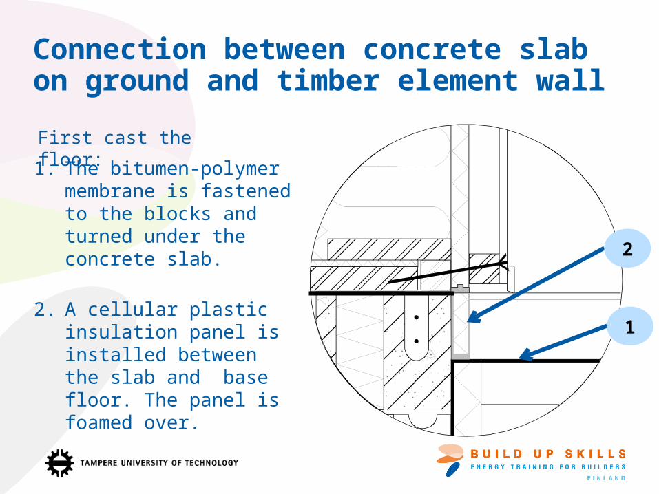
Connection between concrete slab on ground and timber element wall
1. The bitumen-polymer membrane is fastened to the blocks and turned under the concrete slab.
2. A cellular plastic insulation panel is installed between the slab and base floor. The panel is foamed over.
First cast the floor:
1
2

The connection between intermediate floor of timber frame building and exterior wall, using vapour barrier foil to air proof the wall
1. Vapour barrier foil is tightened by screwing (k300) the horizontal battening to the head plate of wall.
2. On the upper floor, tightening is screwed to the base plate of wall.
3. Cellular plastic insulation panels are installed between gaps between beams on the intermediate floor.
4. The edges of the boards are sealed to the beams and battens of the wall with cellular polyurethane foam.
1
2
3
4

The connection between intermediate floor of timber frame building and exterior wall, using cellular plastic insulation panels as vapour proofing
1. Openings for the floor beams are made in the vapour barrier board of the wall.
2. The insulation panel of the wall is led continuously under the intermediate floor and sealed with foam.
3. The beams are foamed into the insulation panel.
2
3
BATTEN
FLOOR BEAM IS FOAMED TO THE VAPOUR
BARRIER BOARD
THE JONIT BETWEEN THE BOARDS
1

1. The vapour barrier foil of wall is led about 20 cm over the side of the roof. The vapour barrier of the roof is overlapped with the vapour barrier of wall about 20 cm.
2. Foil should not be tightened too much. In the corners of the building, vapour barriers are pleated, overlapped and taped together.
3. Vapour barriers are pressed tight by screwing the horizontal battening or by using tightening bricks.
1
2
3
The connection between a timber frame roof and exterior wall, using foil as air barrier

The connection between a timber roof and exterior wall, using foil as a vapour barrier
1. The vapour barrier foil is led up to the exterior wall.
2. The vapour barrier foil of the exterior wall is overlapped with the foil on the roof at the point of the first roofing batten.
3. The connection is tightened with extra batten (screw fastening k300).
Option
2
3
1
Option B

The connection between timber roof and exterior wall, using hard plastic insulation as vapour barrier
1. The junction between the roof and the exterior wall insulation is foamed with polyurethane foam.
2. The ceiling drop is made as counter battening so electrical installations can be led both ways in the installation cavity.
3. The battening of the upper edge of timber lining is fastened after the polyurethane foaming of the boards.
12
3

Joint between massive log wall and diagonal timber roof
1. The vapour proof foil overlaps the end of the wall.
2. The extra part of the vapour proof foil is fitted loosely to the joint between wall and roof.
3. The foil is fastened to the log wall from the edge by taping it and pressing with ceiling strip.
4. Sealing strip is installed to the edge of cellular plastic insulation parallel to the wall. It is pressed up to the insulation panel of the roof by battening.
1
2
3
Foil in the roof
Hard insulation in the roof
4

Joint between massive log wall and timber roof, diagonal roof
1. A chase is made to the log wall parallel to the top of the wall. The chase must be deeper than the space between the logs.
2. The vapour barrier foil of the roof is turned baggy behind the outermost roof bearer.
3. Another edge of foil is pressed to the chase.
4. The battening of the roof is made after the battens are installed.
1
2
34

Sealing window frames
1
23
1. Window frames are sealed near the inner surface with polyurethane foam.
2. In the middle part of the frame polyurethane foam or mineral wool can be used.
3. The foam should not fill the whole gap. The outer edge should be left as a ventilation gap.
4. In a log wall, a settlement gap should be left at the top of the window and filled with mineral wool.
5. Flexible vapour-proof foil is installed around the window. Foil is stapled and taped to the frame wall so that it will stay undamaged when the log settles.
4
2
5
1
3

Insulation and structure of a ventilated 'crawling space' in a low energy house 1/2
1. The sheathing in the 'crawling space' should always be very moisture resistant. The sheathing materials should not be sensitive to mould. The heat resistance of the sheathing should be always at least 0.4 m2 K/W.
2. The moisture transfer between dry ashlar walling and heat insulation or sheathing board should be prevented.
3. Heat insulation covering the entire ground raises the temperature of the ‘crawling space’ which reduces the relative humidity and the favourable conditions for mould development. Organic building materials or waste should not be left on the ground.
4. Heat insulation on the underside of the bearing structures reduces the moisture movements of structures and protects the timber structures from mould forming.
5. Also ventilation of the base floor significantly affects the conditions. The recommended ventilation rate is 0.5-1 1/h.
6. The need for inner frost protection increases because the heat loss through the base floor decreases.
7. The order of work should be planned beforehand so the structures can be sealed properly. The base floor must be made totally airtight.
Ref.: Jukka Lahdensivu, Jommi Suonketo, Juha Vinha, Ralf Lindberg, Elina Manelius, Vesa Kuhno, Kari Saastamoinen, Kati Salminen & Kimmo Lähdesmäki. Matalaenergia- ja passiivitalojen rakenteiden ja liitosten suunnittelu- ja toteutusohjeita (in Finnish). Tampere University of technology.
24
5 7
W/(m*K)Old U = 0.24 W/(m2*K)New U = 0.12 W/(m2*K)
W/(m*K)Old U = 0.19 W/(m2*K)New U = 0.14 W/(m2*K)
1
36

Insulation and structures in the roof space of low energy houses
1. The heavy load of heat insulation and the need for bearing must be considered. The bearing can be improved by making the battening denser or supporting the heat insulation with sheets.
2. The temperature in the roof space will decrease and the relative humidity will increase. Proper conditions for the development of mould will increase.
3. The heat insulating underlay raises the temperature in the roof space and reduces the development of mould.
4. It is recommended to install the heat insulating sheathing board to the exterior surface of the timber frame. Heat resistance of the board min 0,4 m²K/W.
5. As the length of eaves increases so the bend due to snow load increases. This must be considered especially with brick facing.
1
23
4
5
Λ = 0.036 W/(mK)old U = 0.24 W/(m2 K)new U = 0.12 W/(m2 K)
When heat insulation layer Λ = 0.036 W/(mK), the U-value of the old structure
U = 0.15 W/(m2 K)and the value of the new structure U = 0.08
W/(m2 K)
Ref.: Jukka Lahdensivu, Jommi Suonketo, Juha Vinha, Ralf Lindberg, Elina Manelius, Vesa Kuhno, Kari Saastamoinen, Kati Salminen & Kimmo Lähdesmäki. Matalaenergia- ja passiivitalojen rakenteiden ja liitosten suunnittelu- ja toteutusohjeita. Tampereen teknillinen yliopisto.

Consider: What are the most important effects on moisture control when the insulation thickness is increased?
• Heat loss decreases so structures cool down.• Cooling down slows the drying of the building
envelope.• The risk of moisture damage increases.• Tightness of the vapour barrier, air tightness and
ventilation will become paramount.• Weather condition protection will become more
important.

Remember• Thermal insulation should be installed tightly against the frame
• Soft thermal insulation under light pressure.
• Hard thermal insulation is foamed approx. 5-10 cm; the gap for foam should be min 10 mm.
• Tongue and groove joints are installed in the foamed butt joint.
• Vapour-proof foil should not break and is installed to allow movement of the frame.
• The joints of vapour-proof foil should be made as pressure joints if possible.
• In the joints of wind shield board, battening is recommended (at least in the corners).
• The structures should be tight for decades.
• Taping alone is not enough because tapes perish and do not withstand the movements resulting from heat, moisture and snow load.

The good practices and principles required for the energy efficient building have been included in the teaching material. The writers are not responsible for their suitability to individual building projects as such. The individual building projects have to be made according to the building design of the targets in question.

Literature (in Finnish)• RakMK C2. 1998. Kosteus, määräykset ja ohjeet 1998. Suomen rakentamismääräyskokoelma, Ympäristöministeriö, Asunto- ja rakennusosasto.• RakMK D3. 2007. Ympäristöministeriön asetus rakennusten energiatehokkuudesta. Suomen rakentamismääräyskokoelma, Ympäristöministeriö,
Asunto- ja rakennusosasto. • RIL107 2000 Rakennusten veden- ja kosteudeneristysohjeet. 211 sivua. ISBN 951-758-404-0 • Maanvastaisten alapohjarakenteiden kosteustekninen toimivuus. Leivo, V., Rantala, J. TTKK 2003. Tutkimusraportti 120. 106 s. + 13 liites. • Hirsirakennuksen yläpohjan tiiviys - vaikutus lämpöenergiankulutukseen. Leivo, V. TTY 2003. Tutkimusraportti 126. 63 s• Lattialämmitetyn alapohjarakenteen rakennusfysikaalinen toiminta. Leivo, V., Rantala, J. TTY 2005. Tutkimusraportti 128. 140 s.• Rakennusmateriaalien rakennusfysikaaliset ominaisuudet lämpötilan ja suhteellisen kosteuden funktiona. Vinha, J., Valovirta, I., Korpi, M.,
Mikkilä, A., Käkelä, P. TTY 2005. Tutkimusraportti 129. 101 s. + 211 liites.• Maanvastaisten rakenteiden mikrobiologinen toimivuus. Leivo, V. & Rantala, J. TUT 2006. Tutkimusraportti 139. 55 s.• Sisäilmastoseminaari 2007. SIY Raportti 25. Sisäilmayhdistys ry, Teknillinen korkeakoulu, Lvi-tekniikan laboratorio.• Jokisalo, J., Kurnitski, J., Kalamees, T., Eskola, L., Jokiranta, K. Ilmanpitävyyden vaikutus vuotoilmanvaihtoon ja energiankulutukseen pientaloissa.• Korpi, M., Vinha, J. ja Kurnitski J. Massiivirakenteisten pientalojen ilmanpitävyys.• Rakennusfysiikka 2007. Seminaarijulkaisu 1. Tampereen teknillinen yliopisto, Rakennetekniikan laitos. • Kalamees, T., Korpi, M., Eskola, L., Kurnitski, J. ja Vinha, J. Kylmäsiltojen ja ilmavuotokohtien jakauma suomalaisissa pientaloissa ja
kerrostaloasunnoissa.• Korpi, M., Vinha, J. ja Kurnitski J. Pientalojen ja kerrostaloasuntojen ilmanpitävyys.• Airaksinen, M. Ryömintätilan lämpö- ja kosteustekninen toiminta.• Rakennusten ulkovaipan ilmanpitävyys. Polvinen, Martti; Kauppi, Ari; Saarimaa, Juho; Haalahti, Pekka; Laurikainen, Markku. 1983. VTT, Espoo.
143 s. Tutkimuksia / Valtion teknillinen tutkimuskeskus:215. ISBN 951-38-1712-1. • Rakennusten ilmanpitävyyden pysyvyys. Metiäinen, Pertti; Saarimaa, Juho; Saarnio, Pekka; Salomaa, Heikki; Tulla, Kauko; Viitanen, Hannu.
1986. VTT, Espoo. 136 s. + liitt. 29 s. Tutkimuksia / Valtion teknillinen tutkimuskeskus:422. ISBN 951-38-2301-6.• Ilmavirtausten vaikutus rakenteiden lämpö- ja kosteustekniseen toimintaan. Ojanen, Tuomo; Kohonen, Reijo. 1989. VTT, Espoo. 105 s.
Tutkimuksia / Valtion teknillinen tutkimuskeskus. 590. ISBN 951-38-3362-3. ISSN 0358-5077.• Tuulensuojan toimintaperusteet. Ojanen, Tuomo; Kokko, Erkki & Pallari, Marja-Liisa. 1993. VTT, Espoo. 125 s. + 26 liites. VTT Tiedotteita 1478.
ISBN 951-38-4372-6. ISSN 1235-0605.