Embed Size (px)
Citation preview

Topic: Magnetism and Electromagnetic effect
Course: Diploma
Subject:Basics of Electrical Engineering
Unit: 4

• Force on current carrying conductor in magnetic field
• Concept about electrical and magnetic circuit
• Magnetization curve
• Faradays and Lenz’s laws
• Flemings left and Right hand rule
• Induced emf and types
• Administrative management/Fayol’s 14 principles of management
Topics
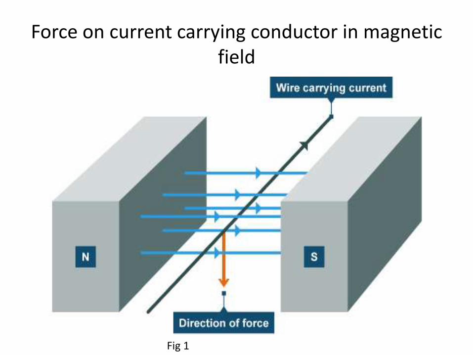
Force on current carrying conductor in magnetic field
Fig 1

the figure, a conductor lying vertically in a uniformhorizontal magnetic field of strength H. If l is the lengthof the conductor tying within this magnetic field and i isthe current through it, then the force experienced bythe conductor will be
F = B.i.l Newton
= μ0.μr.H.i.l Newton
The direction of the force F can also bedetermined by Flemming's Left Hand Rule. As per thisrule, if any one holds out his or her hand with forefinger, second finger and thumb at right angle to eachother, then his or her fore-finger will indicate thedirection of magnetic field, the second finger willindicate the direction of flow of current and the thumbwill give the direction of force or motion of theconductor.In this case the force experienced by theconductor will be
F = B.i.l.sin(θ) Newton.

Comparison between Electric and Magnetic Circuits
Fig 2

Magnetic Equivalent Circuit
Fig 3

Parallel Magnetic Circuit
l2l1
l3
I
N
S1
S2S3
+- NI
13 2
I
II
Loop I
NI = S33 + S11
= H3l3 + H1l1Loop II
NI = S33 + S22
= H3l3 + H2l2Loop III
0 = S11 + S22
= H1l1 + H2l2
Fig 4 self making

Magnetic Circuit with Air Gap
lc
i
N lg
+
F
-
c
g
g
g
g
c
cc
ggcc
gC
g0
g
g
cc
cc
AB
AB
densityFlux
lHlHNiNi
A
l
A
l
;
;
Fig 5 self making
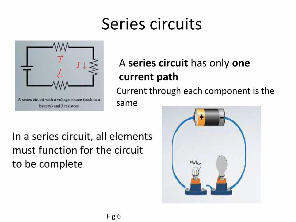
Series circuits
A series circuit has only one current path
Current through each component is the same
In a series circuit, all elements must function for the circuit to be complete
Fig 6

Parallel circuitsA parallel circuit has more
than one current pathbranching from the energysource Voltage across eachpathway is the same. In aparallel circuit, separate currentpaths function independently ofone another. For parallel voltagesources, the voltage is the sameacross all batteries, but thecurrent supplied by eachelement is a fraction of the totalcurrent
Fig 7

Magnetization Curve
HB r0
Behavior of flux density compared with magneticfield strength, if magnetic intensity H increases byincrease of current I, the flux density B in the corechanges as shown.
Fig 8

Faraday’s Law
• Moving the magnet changes the flux B (1).
• Changing the current changes the flux B (2).
• Faraday: changing the flux induces an emf.
i
di/dt
S
EMF N S
iv
e = - dB /dt
The emf induced around a loop equals the rate of change
of the flux through that loop
Faraday’s law
1) 2)

Lenz’s Law• Faraday’s law gives the direction of the induced emf and
therefore the direction of any induced current. Lenz’s law is a simple way to get the directions straight, with less effort.
• Lenz’s Law:
The induced emf is directed so that any induced current flow will oppose the change in magnetic flux (which causes the induced emf).
This is easier to use than to say ...
Decreasing magnetic flux emf creates additional magnetic field
Increasing flux emf creates opposed magnetic field

Fleming's Right-Hand Rule
• The Thumb represents the direction of Motion of the conductor.
• The First finger represents the direction of the Field. (north to south)
• The Second finger represents the direction of the induced or generated Current (the direction of the induced current will be the direction of conventional current; from positive to negative).
Fig 11

Fleming's Left-Hand Rule• A left hand can be held, as
shown in the illustration, so as to represent three mutually orthogonal axes on the thumb, first finger and middle finger.
• Each finger is then assigned to a quantity (mechanical force, magnetic field and electric current). The right and left hand are used for generators and motors respectively.
Fig 12

Induced emf
• Dynamically Induced emf
• Statically Induced emf
Dynamically Induced emf
By moving the conductor keeping the magnetic field system stationary, thus emfinduced in the conductor is called Dynamically Induced emf
Statically Induced emf
• The emf induced by variation of flux is termed as Statically Induced emf
• In this case conductor is held stationary and magnetic field varies.
• Two Types :
1) Self Induced emf
2) Mutually Induced emf

1) Self Induced emf
Fig 13

2) Mutually Induced emf
Fig 14

REFRENCES : IMAGES• https://www.google.co.in/url?sa=i&rct=j&q=&esrc=s&sour
ce=images&cd=&cad=rja&uact=8&ved=0CAcQjRw&url=http%3A%2F%2Fwww.slideshare.net%2Fchristaines%2Fcapacitors-1191029&ei=YOKcVL-aOYWpuwSP04LQCQ&bvm=bv.82001339,d.c2E&psig=AFQjCNGCmbflzcJLZ_sLvIHz0EvVB0OgMw&ust=1419654109104944
• https://www.google.co.in/url?sa=i&rct=j&q=&esrc=s&source=images&cd=&cad=rja&uact=8&ved=0CAcQjRw&url=http%3A%2F%2Fen.wikipedia.org%2Fwiki%2FTypes_of_capacitor&ei=b-acVJCWNs6duQS44YKICQ&bvm=bv.82001339,d.c2E&psig=AFQjCNF0wwlQgan1b5NXe-KMhMkK4FTG8A&ust=1419655106019885

• https://www.google.co.in/url?sa=i&rct=j&q=&esrc=s&source=images&cd=&cad=rja&uact=8&ved=0CAcQjRw&url=http%3A%2F%2Fwww.physicstutorials.org%2Fhome%2Felectrostatics%2Fcapacitors-in-series-and-parallel&ei=rB6dVOfWO9e3uQSDyoLoCQ&bvm=bv.82001339,d.c2E&psig=AFQjCNG9O4B3YuSYCL2dwO0_wA5Hs4lSkA&ust=1419669505063884
• https://www.google.co.in/url?sa=i&rct=j&q=&esrc=s&source=images&cd=&cad=rja&uact=8&ved=0CAcQjRw&url=http%3A%2F%2Fwww.tutorvista.com%2Fcontent%2Fphysics%2Fphysics-iv%2Felectrostatic-potential-capacitance%2Fcombination-capacitors.php&ei=HSCdVOvlMNCWuASC9oHoCQ&bvm=bv.82001339,d.c2E&psig=AFQjCNFQ0A6QJWfTwd33rud9z2GZHuIkHg&ust=1419669881012411

• https://www.google.co.in/url?sa=i&rct=j&q=&esrc=s&source=images&cd=&cad=rja&uact=8&ved=0CAcQjRw&url=http%3A%2F%2Fwww.electrical-engineering-assignment.com%2Fcomparison-of-electric-and-magnetic-circuits&ei=QSKdVIy0N8bauQTR1oCwDw&bvm=bv.82001339,d.c2E&psig=AFQjCNFlsElwkm7c6JuEUnsDOxSXFCNbAg&ust=1419670461373726
• https://www.google.co.in/url?sa=i&rct=j&q=&esrc=s&source=images&cd=&cad=rja&uact=8&ved=0CAcQjRw&url=http%3A%2F%2Fwww.scielo.br%2Fscielo.php%3Fscript%3Dsci_arttext%26pid%3DS1678-58782007000100013&ei=pCWdVNG9HdCyuQSVhIK4CQ&bvm=bv.82001339,d.c2E&psig=AFQjCNEXnQUSAvVM2wVJdOiccNItwgST2w&ust=1419671272346236

• https://www.google.co.in/url?sa=i&rct=j&q=&esrc=s&source=images&cd=&cad=rja&uact=8&ved=0CAcQjRw&url=http%3A%2F%2Fen.wikipedia.org%2Fwiki%2FSeries_and_parallel_circuits&ei=ij-eVMnjNcmPuASZuoCQCg&bvm=bv.82001339,d.c2E&psig=AFQjCNHEIs4pKBpINp3aLED1fUgmfTPJXA&ust=1419743485636976
• https://www.google.co.in/url?sa=i&rct=j&q=&esrc=s&source=images&cd=&cad=rja&uact=8&ved=0CAcQjRw&url=http%3A%2F%2Fwww.electrical4u.com%2Ffleming-left-hand-rule-and-fleming-right-hand-rule%2F&ei=70ueVK3kOpeVuAS5uoDICQ&bvm=bv.82001339,d.c2E&psig=AFQjCNHu4mOSJYjw6JRNWPdFLnxuHDtr9Q&ust=1419746655240849
• https://www.google.co.in/url?sa=i&rct=j&q=&esrc=s&source=images&cd=&cad=rja&uact=8&ved=0CAcQjRw&url=http%3A%2F%2Fwww.electrical4u.com%2Ffleming-left-hand-rule-and-fleming-right-hand-rule%2F&ei=70ueVK3kOpeVuAS5uoDICQ&bvm=bv.82001339,d.c2E&psig=AFQjCNHu4mOSJYjw6JRNWPdFLnxuHDtr9Q&ust=1419746655240849
https://www.google.co.in/url?sa=i&rct=j&q=&esrc=s&source=images&cd=&cad=rja&uact=8&ved=0CAcQjRw&url=http%3A%2F%2Fwww.electrical-engineering-assignment.com%2Fstatically-induced-e-m-f&ei=V02eVPviLMyQuATRyIDYCQ&bvm=bv.82001339,d.c2E&psig=AFQjCNGDdaGwgzvUv0Bs56tykFbLGRNXmw&ust=1419747029291337

• https://www.google.co.in/url?sa=i&rct=j&q=&esrc=s&source=images&cd=&cad=rja&uact=8&ved=0CAcQjRw&url=http%3A%2F%2Fwww.electrical-engineering-assignment.com%2Fstatically-induced-e-m-f&ei=mk2eVNTRC9aMuAS4h4CYCg&bvm=bv.82001339,d.c2E&psig=AFQjCNEcbsGR5vk6vlT0WGHu2DP3mn6hvA&ust=1419747078016874

REFERENCE
• B.L.Theraja, “Electrical Technology Vol.1”, S.ChandPublication.
• D.P.Kothari, “Basic Electrical Engineering”, Tata McGraw-Hill publication.


![L 29 Electricity and Magnetism [6] Review Faraday’s Law of Electromagnetic Induction induced currents electric generator eddy currents electromagnetic](https://img.dokumen.tips/doc/110x75/56649e765503460f94b7766d/l-29-electricity-and-magnetism-6-review-faradays-law-of-electromagnetic.jpg)

![L 28 Electricity and Magnetism [6] magnetism Faraday’s Law of Electromagnetic Induction –induced currents –electric generator –eddy currents Electromagnetic](https://img.dokumen.tips/doc/110x75/56649d035503460f949d6537/l-28-electricity-and-magnetism-6-magnetism-faradays-law-of-electromagnetic.jpg)


![L 30 Electricity and Magnetism [7] Electromagnetic Waves –Faraday laid the groundwork with his discovery of electromagnetic induction –Maxwell added the](https://img.dokumen.tips/doc/110x75/56649f4c5503460f94c6c802/l-30-electricity-and-magnetism-7-electromagnetic-waves-faraday-laid-the.jpg)