Embed Size (px)
Citation preview

POWER SYSTEM AUTOMATION B. E. SEMINAR
Submitted to North Maharashtra University, Jalgaon in Partial Fulfillment of the
Requirements for the Degree of BACHELOR OF ENGINEERING in
Electrical Engineering.
By
Dhiraj Machhindra Bhalerao
(Examination Number )
Guide
Prof. G. K. Andulkar
DEPARTMENT OF
ELECTRICAL ENGINEERING
GOVERNMENT COLLEGE OF ENGINEERING, JALGAON 425002
NOVEMBER 2015

GOVERNMENT COLLEGE OF ENGINEERING, JALGAON
DEPERTMENT OF ELECTRICAL ENGINEERING
CERTIFICATE
This is to certify that the seminar entitled “POWER SYSTEM AUTOMATION”, which is
being submitted herewith for the award of B.E in the result of the work completed by DHIRAJ
M. BHALERAO, under my supervision and guidance within the four walls of the institute and
the same has not been submitted elsewhere for the award of any degree.
(Prof. G. K. Andurkar) (Prof. G. K. Andurkar)
Seminar Guide Head of Electrical department
(Dr. R. P. Borkar) Examiner
Principle, GCOEJ
ii

DECLERATION
I hereby declare that the seminar entitled “POWER SYSTEM AUTOMATION” was carried out
and written by me under the guidance of Prof. Andurkar, professor of electrical department,
Government college of engineering jalgaon. This work has not been previously formed the basis
for the award of any degree or diploma or certificate not has been submitted as elsewhere for the
of award of any degree or diploma.
DHIRAJ M. BHALERAO
Place: Jalgaon
Date:

ACKNOWLEDGEMENT
The successful completion of any task would not be complete without expression of
gratitude to all those who helped in doing that task. I hereby take this opportunity to express our
heartfelt gratitude towards the people who help proved useful to complete my seminar on
“POWER SYSTEM AUTOMATION”
First I wish to express my gratitude sincere thanks to our principal Dr. R.P.Borkar, whose
guidance and suggestions have helped me in completing this seminar report. My special thanks to
Prof. Andurkar for his valuable suggestions in project work.
In particular, I am thankful to all our staff members of Electrical Engineering department
for their whole hearted co-operation. I am thankful to my parents for their blessing and their
valuable moral support. Without their supports I can’t do anything.
Last but not the least I am very much thankful to our friends for supporting me in presentation
of this seminar.
Dhiraj M. Bhalerao
(B.E Electrical)

ABSTRACT
Electrical power distribution system is an important part of electrical system
in delivery of electricity to consumers. Electric power utilities worldwide are
increasingly adopting the computer aided monitoring, control and management of
electric power distribution system to provide better services to consumers.
Therefore, research and development activities worldwide are being carried out to
automate the electric power distribution system utilizing recent advancements in
the area of Information Technology (IT) and data communication system.
In power system automation, data acquisition system plays a major role as a
base of the power system automation. From the recent trends and developments in
Power System Automation, Computerized system Automation is most efficient
compared to normal systems. Computerized Power Network for Data Acquisition
system helps the system and controller to meter and monitor the values for further
manipulations for full-scale power system automation and system controlling.

CHAPTER 1
INTRODUCTION
Power System Automation is one of the important aspects in an electrical power
network that needs careful investigation. In power system automation, data
acquisition system plays a major role as a base of the power system automation.
From the recent trends and developments in Power System Automation,
Computerized system Automation is most efficient compared to normal systems.
Computerized Power Network for Data Acquisition system helps the system and
controller to meter and monitor the values for further manipulations for full-scale
power system automation and system controlling.
The Computerized Data Acquisition for Metering and Monitoring of Power System
Automation can be divided into three general categories as Data collection,
Metering & Monitoring. The Data collection system collects the data from the
Power system Network using the Digital Power Monitors through the current
transformers and potential transformers. The collected data will be Metered by the
Digital Power Monitor where the Monitor consists of a Micro Controller with the
peripherals like memory, A/D converter and Sample and hold circuitry. According
to the programming done in the Microcontroller the Power Monitor will store the
parameters in the memory and it will do all the logical and arithmetic calculations
to manipulate the parameters and to calculate the different Power data’s like KWH,
KVAR, KVA, PF etc,. The collected parameters of the Power System and the
calculated power data can be monitored on the screen of the Digital Power Monitor.
The values will be sent to the Computer System using the Communication system
like Serial Communication RS485 and RS 232 for n no of Power Monitors using
the Data Converter.
This section describes power system automation protection and control which is
aimed at the improvement of the management of power networks is being adopted
by increasing by number of supply authorities. Automation, Protection, Local
control, Operator interfaces, Communication, Remote control and Monitoring

functions, most of which were previously utilized with relays or modules for each
function, are now integrated into multi-function PLC (programmable logic
Controller) based units and interconnected on various types of local area networks.
The components of the system will have a better communication with each other
sharing information through the local area network and systems work similarly
because one sensor is enough to collect one network information and transferred
the information throughout the network using LAN and communication mediums
instead of one sensor per each component as before. To achieve we need a better
system apart from different systems like protection, Communication, RTU’s, IED’s
etc. called as Data acquisition system without the perfect data communication
system the components of the total system can’t perform the right tasks at right time
because of the disturbance in the collected. To overcome this problem we have
designed a better Data Acquisition system with the efficient technology and with
the perfect communication systems to transfer the data. The system is named as
“Computerized Power Network Data Acquisition and Monitoring for Power System
Automation”. The system acquires the data from the power network (data
acquisition) for monitoring. The software was developed to do all the manipulations
and the parameters and data of the system can be viewed in different forms (analog,
digital, graphical). The software developed will be used to view the captured data’s
from the Power Monitor in different forms like Analog Metering, Digital data and
in graphical form. The software will generate the reports for all the different types
of manipulations like power fail, CT or PT fail Low PF etc, the software will save
the data 6 times per day in form of reports.

CHAPTER 2
LITERATURE SURVEY
2.1 Operation system interaction-
The Substation-automation is processed in three parts mainly. First one is Input
signal characterization based on Analog signal (continuous electrical signals such
as active power, reactive power, frequency, Voltage etc.) or Digital signal
(switching signals high or low, isolator open or brake etc.). The second one is
processing the data like analog signal conversion to digital signal via fiber optics.
This is to be carried out by a protocol sequence with a real time operating system
(RTO) and lastly the output analyzing. The results are to be expressed in user
friendly environment like displays. The data communication is done to substation
via telephone lines, fiber optic cables, satellite, power lines. The Open Systems
Interconnection model (OSI) is a conceptual model that characterizes and
standardizes the internal functions of a communication system by partitioning it
into abstraction layers. The OSI model works analogous to letter from sender to
receiver. In the first level the sender written a letter, put it on envelope and drop it
in letter box. In the second level of process the letter is carried out from mailbox to
post-office. Later it was delivered to a carrier from the post office. It was travelled
by certain transmission system and delivered to destination post office, reached to
receiver via carrier, the receiver opens the envelope and reads the information.
2.2 Need of power system automation-
Demand of electricity is increase day by day that’s why transmission lines are
getting to much complex. As the number of consumers and industrial load increase
proper metering is required for exact measurement of power consumption.
Transmission line equivalent circuit parameters are often 25% to 30% in error as
compared to values measured by the SCADA system. These errors cause the
economic dispatch to be wrong, and lead to increased costs or incorrect billing. The
parameter errors also affect contingency analysis, short circuit analysis, distance
relaying, machine stability calculations, transmission planning, and state estimator
analysis. An economic example is used to demonstrate the affect of transmission
line errors. SCADA measurements from several utilities are used to compute the
'real world' value of the transmission line parameters. State estimation with the
estimated parameters is compared to the computations using the theoretical
Electric utilities must meet increasing demand for reliable power distribution while
coping with decreasing tolerance for disruptions and outages. More than ever,
utilities are squeezed to do more with less, and recognize the need to improve the
efficiency of their power generation and distribution systems.
Fortunately, many areas of the existing electrical distribution system can be
improved through automation. Furthermore, by automating the distribution system
now, utilities will be ready to meet the challenges of integrating intermittent supply
sources like solar, wind and other distributed energy resources (DERs).
Automating electrical distributions systems by implementing a supervisory control
and data acquisition (SCADA) system is the one of the most cost-effective solutions
for improving reliability, increasing utilization and cutting costs.
2.3 Status of automation in the India-
Electric utilities, all around the world, have realized the problems associated with
vertically integrated electric power systems and therefore they are moving towards
unbundled model of generation companies(GENCOs), transmission companies
(TRANSCOs), distribution companies (DISCOs), and energy service companies
(ESCOs). In the past, all electric power distribution-related functions could be
transparently coordinated along the complete supply chain. In the future, many
distribution companies will manage third-party contacts by delivering bulk power
from GENCOs and TRANSCOs to meters owned by ESCOs. At the same time,
many state regulatory commissions are considering the viability of retail wheeling
(small generators connected to the distribution system selling electricity directly to
consumers). In addition to planning and operating difficulties, retail wheeling asks
distribution systems to perform the functions for which they were not designed. In
view of the above, on-line information, remote control and efficient management
system are required for power distribution utilities. Considering the extensive size
of the network, these tasks can be efficiently achieved through the intervention of
information technology utilizing the available high- speed computer and
communication technology. This system of monitoring and control of electric
power distribution networks is also called as “Distribution Automation (DA)”
system. The Institute of Electrical and Electronic Engineers (IEEE) has defined
Distribution Automation System (DAS) as a system that enables an electric utility
to remotely monitor, coordinate and operate distribution components, in a real-time
mode from remote locations. The distribution automation system is based on an
integrated technology, which involves collecting data and analyzing information to
make control decisions, implementing the appropriate control decisions in the field,
and also verifying that the desired result is achieved. The location, from where
control decisions are initiated, is generally called Distribution Control Centre
(DCC).
At present, power utilities have realized the need for full scale distribution
automation to achieve on-line system information and remote control system. This
is required in order to fully accomplish the restricting (GENCOs, TRANSCOs,
DISCOs, and ESCOs) of the power system to the level of retail wheeling [1, 5]. On
the other hand, the main motivation for accepting the distribution automation in
developing countries such as India is to improve operating efficiency of distribution
system. This indicates worldwide interest for distribution automation at present.
Looking at the interest of power utilities for distribution automation, academic
institutions are now taking interest to introduce courses and R& D activities in the
field of DA in the regular academic curriculum. A list of possible research areas
and activities for future is also proposed for power distribution automation.[2]
CHAPTER 3
POWER SYSTEM & AUTOMATION
3.1 Power system-
An electric power system is a network of electrical components used to supply,
transmit and use electric power. An example of an electric power system is the
network that supplies a region's homes and industry with power—for sizable
regions, this power system is known as the grid and can be broadly divided into
the generators that supply the power, the transmission system that carries the power
from the generating centres to the load centres and the distribution system that feeds
the power to nearby homes and industries. Smaller power systems are also found in
industry, hospitals, commercial buildings and homes. The majority of these systems
rely upon three-phase AC power—the standard for large-scale power transmission
and distribution across the modern world.
Generating stations, transmission lines and distribution system are the main component
of an electrical system. Generating station and distributed substation are connected
through transmission lines, which also connects one power system to another. A
distribution system connects all the loads in a particular area to the transmission line.[1]
3.2 How does Power reach us?-
Electric power is normally generated at 11-25kV in a power station. To transmit over long
distances, it is then stepped-up to 400kV, 220kV or 132kV as necessary. Power is carried
through a transmission network of high voltage lines. Usually, these lines run into
hundreds of kilometers and deliver the power into a common power pool called the grid.
The grid is connected to load centers (cities) through a sub- transmission network of
normally 33kV (or sometimes 66kV) lines. These lines terminate into a 33kV (or 66kV)
substation, where the voltage is stepped-down to 11kV for power distribution to load
points through a distribution network of lines at 11kV and lower. The power network,
which generally concerns the common man, is the distribution network of 11kV lines or
feeders downstream of the 33kV substation. Each 11kV feeder which emanates from the
33kV substation branches further into several subsidiary 11kV feeders to carry power
close to the load points (localities, industrial areas, villages, etc.,). At these load points, a
transformer further reduces the voltage from 11kV to 415V to provide the last-mile
connection through 415V feeders (also called as Low Tension (LT) feeders) to individual
customers, either at 240V (as single-phase supply) or at 415V (as three- phase supply). A
feeder could be either an overhead line or an underground cable. In urban areas, owing
to the density of customers, the length of an 11kV feeder is generally up to 3 km. On the

other hand, in rural areas, the feeder length is much larger (up to 20 km). A 415V feeder
should normally be restricted to about 0.5-1.0 km. duly long feeder’s lead to low voltage
at the consumer end.

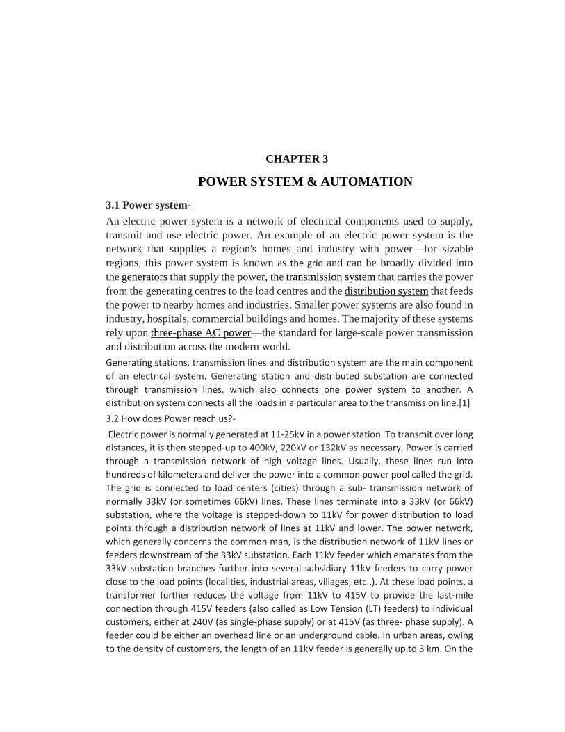
3.3 Automation-
The word ‘Automation’ is derived from greek words “Auto” (self) and “Matos”
(moving). Automation therefore is the mechanism for systems that “move by itself”.
However, apart from this original sense of the word, automated systems also
achieve significantly superior performance than what is possible with manual
systems, in terms of power, precision and speed of operation.
Automation is a set of technologies that results in operation of machines and
systems without significant human intervention and achieves performance superior
to manual operation
The application of machines to tasks once performed by human beings or,
increasingly, to tasks that would otherwise be impossible. Although the term
mechanization is often used to refer to the simple replacement of human labour by
machines, automation generally implies the integration of machines into a self-
governing system
Fig 3.2 Automation system

3.4 Power system Automation-
Power System Automation is a system for managing, controlling and protecting the
various components connected to the power network. It obtains the real time
information from the system, local and remote control applications with advanced
electrical system protection. The core of power system automation stands on local
intelligence, data communications with supervisory control and monitoring.
Electrical Protection
Control
Measurement
Monitoring
Data communication
Electrical Protection- Electrical Protection is the most important concept of the
Power system Automation, to protect the equipment and personnel and to limit the
damage at fault. It is a local function and it has the capability to function
independently from the Automation if necessary, although it is a part of Power
system Automation the function of electrical protection never restricted in Power
system Automation.
Control- Control application of a Power system Automation includes local and
remote control. Local control consists of actions the control device can logically
take by itself (Bay interlocking, switching sequences, and synchronizing check).
Human intervention is limited and the risk was greatly reduced. Remote control
functions to control Substations remotely from the SCADA. Commands can be
given directly to the remote control devices (open and close of circuit breakers,
relay settings, requests for information from the SCADA station). This eliminates
the personnel performance switching operations, actions can be performed faster.
A safe working environment is created for personnel and the operator or engineer
at the SCADA has a complete over view of the entire Power network.
Measurement- Measurement is one of important concept in Power system
Automation. The real time information about a substation or equipment is collected
and displayed in the control center and stored in a data base for further
manipulations, It erases the personnel to go to substation or switching area collect
the information cutting down workloads. The information collected can assist in
doing network studies like load flow analysis, planning ahead and preventing
disturbances in the Power network. Previously the word ‘Measurement’ refer to
voltage, current and frequency, and the word ‘Metering’ refer to power, reactive
power and energy (KWh). The different terms used because different instruments
were used for these applications, now the two functions are integrated in modern
devices hence the terms are used interchangeably in the text.
Monitoring- Monitoring is specified for the maintenance of the Power system
Automation. It monitors sequence of records, status and condition of the system,
maintenance information and relay settings etc. The information can help in fault
analysis, what where when why it happened. It is used to improve the efficiency of
the system. Data Communication Normally Communication forms a core for any
system, in Power system Automation Data communication forms core of the power
system Automation. Without communication the local device and protection tasks
can be performed individually. But without data communication there is no mean
to say Power system Automation.[5]

CHAPTER 4
SUPERVISORY CONTROL AND DATA ACQUISITION
(SCADA)
4.1 What is SCADA-
SCADA is an acronym for Supervisory Control and Data Acquisition. SCADA
systems are used to monitor and control a plant or equipment in industries such as
telecommunications, water and waste control, energy, oil and gas refining and
transportation. These systems encompass the transfer of data between a SCADA
central host computer and a number of Remote Terminal Units (RTUs) and/or
Programmable Logic Controllers (PLCs), and the central host and the operator
terminals. A SCADA system gathers information (such as where a leak on a
pipeline has occurred), transfers the information back to a central site, then alerts
the home station that a leak has occurred, carrying out necessary analysis and
control, such as determining if the leak is critical, and displaying the information in
a logical and organized fashion. These systems can be relatively simple, such as one
that monitors environmental conditions of a small office building, or very complex,
such as a system that monitors all the activity in a nuclear power plant or the activity
of a municipal water system. Traditionally, SCADA systems have made use of the
Public Switched Network (PSN) for monitoring purposes. Today many systems are
monitored using the infrastructure of the corporate Local Area Network
(LAN)/Wide Area Network (WAN). Wireless technologies are now being widely
deployed for purposes of monitoring.
4.2 Components of SCADA-
SCADA systems consist of:
• One or more field data interface devices, usually RTUs, or PLCs, which interface to field sensing devices and local control switchboxes and valve actuators
• A communications system used to transfer data between field data interface devices and control units and the computers in the SCADA central host. The system can be radio, telephone, cable, satellite, etc., or any combination of these.
• A central host computer server or servers (sometimes called a SCADA Center, master station, or Master Terminal Unit (MTU)
• A collection of standard and/or custom software [sometimes called Human Machine Interface (HMI) software or Man Machine Interface (MMI) software] systems used to provide the SCADA central host and operator terminal application, support the communications system, and monitor and control remotely located field data interface devices
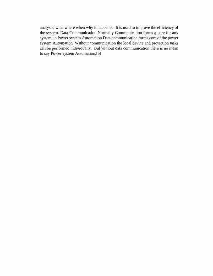
Figure 4.1 shows a very basic SCADA system, while Figure 4.2 shows a typical
SCADA system. Each of the above system components will be discussed in detail
in the next sections.
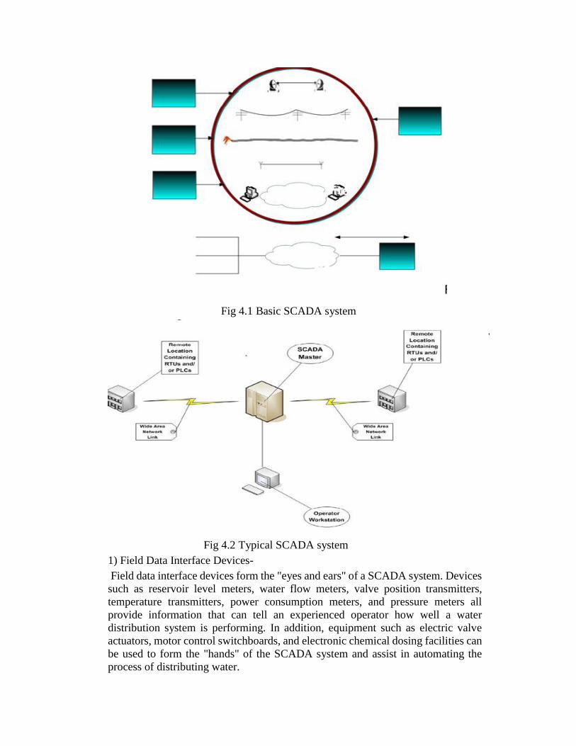
Fig 4.1 Basic SCADA system
Fig 4.2 Typical SCADA system
1) Field Data Interface Devices-
Field data interface devices form the "eyes and ears" of a SCADA system. Devices
such as reservoir level meters, water flow meters, valve position transmitters,
temperature transmitters, power consumption meters, and pressure meters all
provide information that can tell an experienced operator how well a water
distribution system is performing. In addition, equipment such as electric valve
actuators, motor control switchboards, and electronic chemical dosing facilities can
be used to form the "hands" of the SCADA system and assist in automating the
process of distributing water.

However, before any automation or remote monitoring can be achieved, the
information that is passed to and from the field data interface devices must be
converted to a form that is compatible with the language of the SCADA system. To
achieve this, some form of electronic field data interface is required. RTUs, also
known as Remote Telemetry Units, provide this interface. They are primarily used
to convert electronic signals received from field interface devices into the language
(known as the communication protocol) used to transmit the data over a
communication channel.
The instructions for the automation of field data interface devices, such as pump
control logic, are usually stored locally. This is largely due to the limited bandwidth
typical of communications links between the SCADA central host computer and
the field data interface devices. Such instructions are traditionally held within the
PLCs, which have in the past been physically separate from RTUs. A PLC is a
device used to automate monitoring and control of industrial facilities. It can be
used as a stand-alone or in conjunction with a SCADA or other system. PLCs
connect directly to field data interface devices and incorporate programmed
intelligence in the form of logical procedures that will be executed in the event of
certain field conditions.
PLCs have their origins in the automation industry and therefore are often used in
manufacturing and process plant applications. The need for PLCs to connect to
communication channels was not great in these applications, as they often were only
required to replace traditional relay logic systems or pneumatic controllers. SCADA
systems, on the other hand, have origins in early telemetry applications, where it
was only necessary to know basic information from a remote source. The RTUs
connected to these systems had no need for control programming because the local
control algorithm was held in the relay switching logic.
As PLCs were used more often to replace relay switching logic control systems,
telemetry was used more and more with PLCs at the remote sites. It became
desirable to influence the program within the PLC through the use of a remote
signal. This is in effect the "Supervisory Control" part of the acronym SCADA.
Where only a simple local control program was required, it became possible to store
this program within the RTU and perform the control within that device. At the
same time, traditional PLCs included communications modules that would allow
PLCs to report the state of the control program to a computer plugged into the PLC
or to a remote computer via a telephone line. PLC and RTU manufacturers therefore
compete for the same market.
As a result of these developments, the line between PLCs and RTUs has blurred
and the terminology is virtually interchangeable. For the sake of simplicity, the term
RTU will be used to refer to a remote field data interface device; however, such a
device could include automation programming that traditionally would have been
classified as a PLC.
2) Communications Network-
The communications network is intended to provide the means by which data can
be transferred between the central host computer servers and the field-based RTUs.

The Communication Network refers to the equipment needed to transfer data to and
from different sites. The medium used can either be cable, telephone or radio.
The use of cable is usually implemented in a factory. This is not practical for
systems covering large geographical areas because of the high cost of the cables,
conduits and the extensive labor in installing them. The use of telephone lines (i.e.,
leased or dial-up) is a more economical solution for systems with large coverage.
The leased line is used for systems requiring on-line connection with the remote
stations. This is expensive since one telephone line will be needed per site. Dial-up
lines can be used on systems requiring updates at regular intervals (e.g., hourly
updates). Here ordinary telephone lines can be used. The host can dial a particular
number of a remote site to get the readings and send commands.
Remote sites are usually not accessible by telephone lines. The use of radio offers
an economical solution. Radio modems are used to connect the remote sites to the
host. An on-line operation can also be implemented on the radio system. For
locations where a direct radio link cannot be established, a radio repeater is used to
link these sites.
Historically, SCADA networks have been dedicated networks; however, with the
increased deployment of office LANs and WANs as a solution for interoffice
computer networking, there exists the possibility to integrate SCADA LANs into
everyday office computer networks.
The foremost advantage of this arrangement is that there is no need to invest in a
separate computer network for SCADA operator terminals. In addition, there is an
easy path to integrating SCADA data with existing office applications, such as
spreadsheets, work management systems, data history databases, Geographic
Information System (GIS) systems, and water distribution modeling systems.
3) Central Host Computer -
The central host computer or master station is most often a single computer or a
network of computer servers that provide a man-machine operator interface to the
SCADA system. The computers process the information received from and sent to
the RTU sites and present it to human operators in a form that the operators can
work with. Operator terminals are connected to the central host computer by a
LAN/WAN so that the viewing screens and associated data can be displayed for the
operators. Recent SCADA systems are able to offer high resolution computer
graphics to display a graphical user interface or mimic screen of the site or water
supply network in question. Historically, SCADA vendors offered proprietary
hardware, operating systems, and software that was largely incompatible with other
vendors' SCADA systems. Expanding the system required a further contract with
the original SCADA vendor. Host computer platforms characteristically employed
UNIX-based architecture, and the host computer network was physically removed
from any office-computing domain.
However, with the increased use of the personal computer, computer networking
has become commonplace in the office and as a result, SCADA systems are now

available that can network with office-based personal computers. Indeed, many of
today's SCADA systems can reside on computer servers that are identical to those
servers and computers used for traditional office applications. This has opened a
range of possibilities for the linking of SCADA systems to office-based applications
such as GIS systems, hydraulic modeling software, drawing management systems,
work scheduling systems, and information databases.
4) Operator Workstations and Software Components-
Operator workstations are most often computer terminals that are networked with
the SCADA central host computer. The central host computer acts as a server for
the SCADA application, and the operator terminals are clients that request and send
information to the central host computer based on the request and action of the
operators.
An important aspect of every SCADA system is the computer software used within
the system. The most obvious software component is the operator interface or Man
Machine Interface/Human Machine Interface (MMI/HMI) package; however,
software of some form pervades all levels of a SCADA system. Depending on the
size and nature of the SCADA application, software can be a significant cost item
when developing, maintaining, and expanding a SCADA system. When software is
well defined, designed, written, checked, and tested, a successful SCADA system
will likely be produced. Poor performances in any of these project phases will very
easily cause a SCADA project to fail.
Many SCADA systems employ commercial proprietary software upon which the
SCADA system is developed. The proprietary software often is configured for a
specific hardware platform and may not interface with the software or hardware
produced by competing vendors. A wide range of commercial off-the-shelf (COTS)
software products also are available, some of which may suit the required
application. COTS software usually is more flexible, and will interface with
different types of hardware and software. Generally, the focus of proprietary
software is on processes and control functionality, while COTS software
emphasizes compatibility with a variety of equipment and instrumentation. It is
therefore important to ensure that adequate planning is undertaken to select the
software systems appropriate to any new SCADA system.
Software products typically used within a SCADA system are as follows:
• Central host computer operating system: Software used to control the central host computer hardware. The software can be based on UNIX or other popular operating systems.
• Operator terminal operating system: Software used to control the central host computer hardware. The software is usually the same as the central host computer operating system. This software, along with that for the central host computer, usually contributes to the networking of the central host and the operator terminals.
• Central host computer application: Software that handles the transmittal and reception of data to and from the RTUs and the central host. The software also

provides the graphical user interface which offers site mimic screens, alarm pages, trend pages, and control functions.
• Operator terminal application: Application that enables users to access information available on the central host computer application. It is usually a subset of the software used on the central host computers.
• Communications protocol drivers: Software that is usually based within the central host and the RTUs, and is required to control the translation and interpretation of the data between ends of the communications links in the system. The protocol drivers prepare the data for use either at the field devices or the central host end of the system.
• Communications network management software: Software required to control the communications network and to allow the communications networks themselves to be monitored for performance and failures.
• RTU automation software: Software that allows engineering staff to configure and maintain the application housed within the RTUs (or PLCs). Most often this includes the local automation application and any data processing tasks that are performed within the RTU.
The preceding software products provide the building blocks for the application-
specific software, which must be defined, designed, written, tested, and deployed
for each SCADA system.[3]
4.3 Classification & Working of SCADA in Power system automation-
Power system automation is classified into 2 types-
a) Substation Automation
b) Distribution Automation
a) Substation Automation- Substation automation is not a new concept. Substations
have been equipped to perform automatic re closing, bus sectionalizing, load
transfers, capacitor switching, etc. for many years. In the past, these and other
functions were implemented using a combination of control panels, auxiliary relays,
switches, lights, meters, transducers and extensive wiring and cabling. In many
applications today, this perception is probably because developments in substation
equipment have expanded the potential capabilities of substation. Automation far
beyond that which could previously be reasonably accomplished. The principal
development is generically defined as an Intelligent Electronic Device (IED) which
typically consists of one or more Programmable Logic Controllers and
communications ports; with the ability to transmit data and execute control
commands, and frequently provide a local user interface. Typical examples are
relays, meters, and specialized sensors. Prior to the introduction of Numerical
relays, the protection and control of a very small substation consisting of one
incoming line, one transformer and two feeders would require four large panels
filled with relays, switches and lights. Only one panel is required when Numerical
relays are used. Interestingly, at the same time the space requirements are reduced
by a factor of four, so the installed cost.
Advances in communications technology are used to tie everything together into a
useful network. Within the substation, a single high-speed Local Area Network
(LAN) is used to transmit data and control commands, replacing the extensive and
costly cables that had been required. At the present time, a number of different LAN
techniques and protocols are in use. The industry is actively working on
development of a new standard LAN definition that will be based on the use of
Ethernet and Manufacturing Messaging Specification (MMS) and will be
compatible with the Utility Communications Architecture (UCA). There are already
many techniques for moving data out of the substation to a master station or to other
substations. These include the use of leased or dedicated telephone lines, dial-up
phone lines, cellular telemetry techniques, satellite transmissions, various flavors
of radio techniques and fiber-optic networks. Basically, this variety of
communications methods results in the ability to transmit large amounts of
information at a rapidly declining cost per bit. The combination of PLC based
devices and communications technology creates the ability to obtain more
information about the power system and the equipment being used. Power system
variables include magnitude and angle of voltages and currents, real and reactive
power, frequency, power factors etc. Information is available regarding the
initiating event for relay operation, the location of faults, and fault analysis.
Specialized sensors and transducers are used to build a database relating to
equipment condition and use; so that analysis techniques can be used to determine
equipment condition and base maintenance activities on actual condition rather than
time schedules. Within the substation, the use of Programmable Logic Controllers
or other types of computers opens up a vast array of automation possibilities.
Complex schemes for dead bus and dead line re-closing can be implemented, with
the sequence being based on actual power system conditions that exist at the time.
Re-closing of circuits can be modified based on cold load pickup requirements.
Load transfers between busses and transformers can be made to protect against
transformer overloads. Bus voltages and power factors can be tightly controlled to
minimize losses or voltage variations. Supplementary measurements and inputs can
be used to initiate automatic equipment reenergizing after a transformer or bus
differential.
Distribution Automation-
The above figure has shown the single line diagram of SCADA system in
load dispatch centre. Its consist of different elements like Transducer, RTU
(Remote terminal unit), PLCC (power line carrier communication), MMI (Man
machine interface),Telecontrol interface.
Initially the data sense by Transducer, the Transducer is device which sense
the changes in power system parameter like voltage, load current, reactive power,
real power and status of circuit breaker, isolator and when converted in suitable
form ,which is useful for further process. The Transducer is connected at an
auxiliary terminal of current transformer and potential transformer. The
Transducers are two types, first is Analog Transducer and second is Digital
Transducer. The Analog current Transducer is used for measuring the current,

Similarly the Analog voltage Transducer used for measuring the voltage. If we
required measuring the Reactive power and real power of the line, at this instant
both current and potential transducers are used. The Digital Transducer is used for
observing the status of the circuit breaker and isolator. The digital transducer is
transfer the signal in binary form or 0and 1.If the circuit breaker and isolator is
open, then the value of signal is zero and vice- versa .the signal is transmitted from
transducer to RTU.
The output +/- 10mA is indicates that the SCADA system is bidirectional. The RTU
send a massage to the master unit, after receiving a massage the master unit is send
the acknowledgement signal to the RTU.If due to any reason a massage is not
display in proper manner then this instant the master unit is send the request signal
to RTU. The RTU consist of three unit 1) AE (analog input card), 2) DE (digital
input card) and 3) FWP (frequency width pulse).
The analog input card is collected the analog data like Load current, Voltage,
Reactive power, Real power and Frequency. The digital input card is collected the
digital data like status of circuit breaker and isolator .In RTU this analog and digital
signal is converted into a digital form by protocol.
The width of the pulse is maintained or control by FWP, the frequency width pulse
maintains the pulse at 0 to250 binary value. This binary value is transferred to the
variable frequency telemetry is increases the frequency level from 2.5KHz to
4KHz.It transfer the signal at 4KHz and received a signal at 2.4KHz.This signal is
transferred to the power line carrier communication. The PLCC is a communication
media; its depending on frequency range and the distance between RTU and master
unit. The data is transferred through the protection line of the power system.
The signal is received by PLCC and VFT in Load Dispatch Center after this unit, a
signal is received by Tele control interface, the Tele control interface is converted
the signal in spectrum form. The MMI (man machine interference) is continuously
data on the monitor, which is helpful for the dispatcher to take the decision as per
system requirement.[7]

Fig 4.3 Single line diagram used in SCADA system
F
MW TRANSDUCER
800 - 0 - 800 O/P +/ -
10 mA A.E.
D.E.
FWP to 0 250
Binary value
VFT 2.4
– 4 KHz PLCC
50 –
KHZ 500
VFT 2.4 – 4 KHz
PLCC
50 – 500 KHZ Tele
Control Interface
MMI 220
RTU

CHAPTER 5
CONCLUSION
1. Improved quality of service and reduced manpower requirements
2. Improved reliability with reduced system implementation costs
3. Maintenance/expansion of customer base and Reduced operating costs
4. High value service provider and reduced maintenance costs
5. Added value services with the ability to defer capacity addition projects
6. Improved customer access to information and also improved information for
engineering decisions
7. Enterprise information accessibility along with improved information for
planning decisions
8. Flexible Billing Options and reduced customer outage minutes
The SCADA system plays an important role in power system automation. A rich
functionality, extensive control and supervision facilities. Reliability and
robustness. These systems are used for mission critical industrial process where
reliability and performances paramount. In addition, specific development is
performed within a well-established control center that enhances reliability and
robustness. Technical support and maintenance are made easy in any power system
process. The application of SCADA in electrical engineering results in reduction of
complexity for the operators to handle the electrical components.

REFERENCES
1. J. B. Gupta, Electrical power system, SK publications, pg no. part II 1 to 10, 2005
2. Gaur & Gaur, Automation in power distribution system: Present status,
E-ISSN0976-7916, Page no. 1-3, 2012
3. Jason stamp & Michel Berg, Reference Model for Control and Automation
Systems in Electrical Power, vol. 1.2 ,8-16, 10 oct. 2005
4. National communication system, Supervisory Control And Data Acquisition
(SCADA) systems, Tech. info. Bulletin, Vol. NCS TIB 04-1, Oct 2004
5. Power system automation, NPTEL, Dept. of elect engg., page no. 1-16, Sept.
2015
6. Shabnam Rukhsar, SCADA in Transmission Line, IOSR Journal of Electrical
and Electronics Engineering, e-ISSN: 2278-1676, p-ISSN: 2320-3331,Page no. 67
to 71,2014
7. http://www.iosrjournals.org