Embed Size (px)
Citation preview

SHRI VAISHNAV INSTITUTE OF TECHNOLOGY AND SCIENCE
PRESENTATION ON DEPLOYMENT DIAGRAMS SESSION:-2015 -2016
SUBMITTED BY: GUIDED BY: MR. BHARAT PAHADIYA REENA CHOUHAN[0802IT121037] VIJAY PANCHOLI[0802TX121054]
deployment diagrams• show the structure of the run-time system• capture the hardware that will be used toimplement the system and the links betweendifferent items of hardware.• Model physical hardware elements and thecommunication paths between them• Plan the architecture of a system• Document the deployment of softwarecomponents or nodes
deployment basic• What existing systems will system need to interact or integrate with?• How robust does system need to be (e.g., redundant hardware in case of a system failure)?• What and who will connect to or interact with system, and how will they do it• What middleware, including the operating system and communications approaches and protocols, will system use?• What hardware and software will users directly interact with (PCs, network computers, browsers, etc.)?• How will you monitor the system once deployed?• How secure does the system need to be (needs a firewall, physically secure hardware, etc.)?
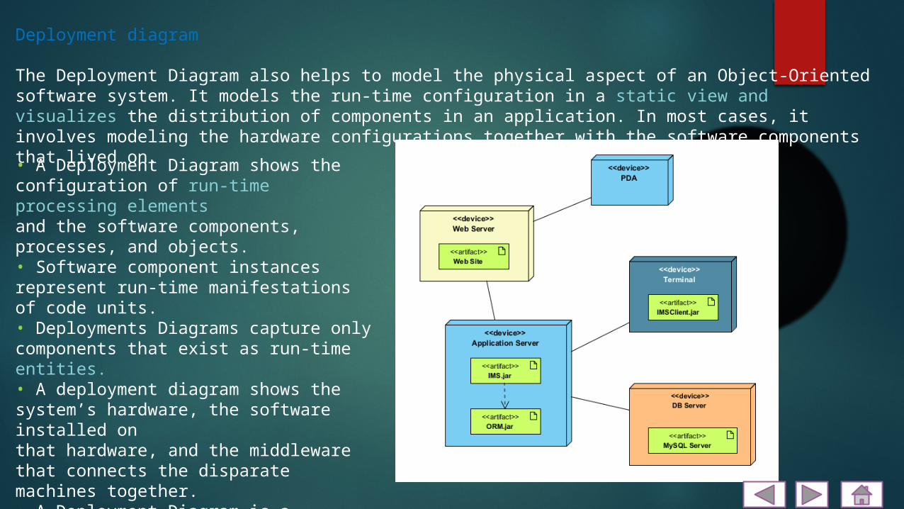
Deployment diagram
The Deployment Diagram also helps to model the physical aspect of an Object-Oriented software system. It models the run-time configuration in a static view and visualizes the distribution of components in an application. In most cases, it involves modeling the hardware configurations together with the software components that lived on.• A Deployment Diagram shows the configuration of run-time processing elementsand the software components, processes, and objects.• Software component instances represent run-time manifestations of code units.• Deployments Diagrams capture only components that exist as run-time entities.• A deployment diagram shows the system’s hardware, the software installed onthat hardware, and the middleware that connects the disparate machines together.• A Deployment Diagram is a collection of one or more deployment diagrams withtheir associated documentation.• Deployment diagrams show the physical configurations of software andhardware.

DefinitionA generalization is a taxonomic relationship between a more general classifier and a more specific classifier. Each instance of the specific classifier is also an indirect instance of the general classifier. Thus, the specific classifier inherits the features of the more general classifier.
An instance specification is extended with the capability of being a deployment target in a deployment relationship, in the case that it is an instance of a node. It is also extended with the capability of being a deployed artifact, if it is an instance of an artifact.
An interface is a kind of classifier that represents a declaration of a set of coherent public features and obligations. An interface specifies a contract; any instance of a classifier that realizes the interface must fulfill that contract.
An association declares that there can be links between instances of the associated types. A link is a tuple with one value for each end of the association, where each value is an instance of the type of the end.

Deployment PlanningHow will your system be installed?• If different versions of the system will bein production at the same time, how will youresolve differences?• What physical sites do you need to deploy toand in what order?• How will you train your users?
Communication AssociationA communication associations between nodes indicates acommunication path between the nodes that allowscomponents on the nodes to communicate with oneanother

• How will your system be installed?• Who will install it? How long should it take to install?• Where the installation possibly fail? How do you back out if theinstallation fails? How long does it take to back out?• What is your installation window (during what time period can you installyour system)?• What backups do you need before installation? Do you need to do a dataconversion?• How do you know that the installation was successful?• If different versions of the system will be in production at the same time, howwill you resolve differences?• What physical sites do you need to deploy to and in what order?• How will you train your support and operations staff?• Do you need to deploy a production support system so that the supportstaff uses their own environment to simulate problems?• How will you train your users?• What documentation, and in what formats and languages, do your users,and support and operation staff need?• How will updates to documentation be deployed

How to produce deployment diagrams
1. Decide on the purpose of the diagram2. Add nodes to the diagram3. Add communication associations to thediagram4. Add other elements to the diagram, such ascomponents or active objects, if required5. Add dependencies between components andobjects, if required
UML Deployment DiagramsDeployment diagram shows execution architecture of systems that represent the assignment (deployment) of software artifacts to deployment targets (usually nodes).Nodes represent either hardware devices or software execution environments. They could be connected through communication paths to create network systems of arbitrary complexity. Artifacts represent concrete elements in the physical world that are the result of a development process and are deployed on nodes.Note, that components were directly deployed to nodes in UML 1.x deployment diagrams. In UML 2.x artifacts are deployed to nodes, and artifacts could manifest (implement) components. So components are now deployed to nodes indirectly through artifacts.The following nodes and edges are typically drawn in a UML deployment diagram: deployment, artifact, association between artifacts, dependency between artifacts, component, manifestation, node, device, execution environment, composition of nodes, communication path, deployment specification, deployment specification dependency, deployment specification association.You can find some deployment diagrams examples here:•Web application deployment•Web application manifestation•Multilayered load balancing•Clustered deployment of J2EE web application•Apple iTunes deployment•Android application deployment

Manifestation
Manifestation is an abstraction relationship which represents concrete physical rendering (implementation) of one or more model elements by an artifactor utilization of the model elements in the construction or generation of the artifact. An artifact manifests one or more model elements.Note, that since UML 2.0 artifacts can manifest any packageable elements, not just components as it was in previous versions of UML.The artifact owns the manifestations, each representing the utilization of a packageable element.Specific profiles are expected to stereotype the manifestation relationship to indicate particular forms of manifestation. For example, «tool generated» and «custom code» might be two manifestations for different classes embodied in an artifact.A manifestation is notated in the same way as abstraction, i.e. as a dashed line with an open arrow head directed from artifact to packageable element, (e.g. to component or package) and is labeled with the keyword «manifest».

Deployment Target
Instance specification was extended in UML 2.0 to allow instance of a node to be deployment target in a deployment relationship.Property was also extended in UML 2.0 with the capability of being a deployment target in a deployment relationship. This enables modeling the deployment to hierarchical nodes that have properties functioning as internal parts.Deployment target owns the set of deployments that target it.Deployment target has no specific notation by itself, see notations for subclasses.
Artifacts are deployed to deployment targets. Deployment target is the location for a deployed artifact.

Node is a deployment target which represents computational resource upon which artifacts may be deployed for execution.Node is shown as a perspective, 3-dimensional view of a cube.
Node is associated with deployments of artifacts and indirectly with packageable elements that are involved in the manifestations by the artifact that is deployed on the node.Nodes can be interconnected with communication paths. Communication paths can be defined between nodes such as application server and database server to define the possible communication paths between the nodes. Specific network topologies can then be defined through links between node instances.Node is specialized by:•device•execution environment
Application Server Node
Node

Hierarchical NodeHierarchical nodes can be modeled using composition or by defining an internal structure. Internal structure of the node is defined in terms of parts andconnectors. Parts of the node could be only nodes.
Application server box runs several web servers and J2EE servers

A device is a node which represents a physical computational resource with processing capability upon which artifacts may be deployed for execution.A device is rendered as a node (perspective, 3-dimensional view of a cube) annotated with keyword «device».
Device
Application Server device
UML provides no standard stereotypes for devices. Examples of non-normative stereotypes for devices are:•«application server»•«client workstation»•«mobile device»•«embedded device»Device may be depicted using custom icon. Profiles, stereotypes, and tagged values could be used to provide custom icons and properties for the devices.

An execution environment is a (software) node that offers an execution environment for specific types of components that are deployed on it in the form of executable artifacts. Components of the appropriate type are deployed to specific execution environments.Execution environment implements a standard set of services that components require at execution time (at the modeling level these services are usually implicit). For each deployment of component, aspects of these services may be determined by properties in a deployment specification for a particular kind of execution environment.Execution environment is notated the same way as a node (perspective, 3-dimensional view of a cube), annotated with the standard UML stereotype «executionEnvironment».
Execution Environment
Execution environment - J2EE Container
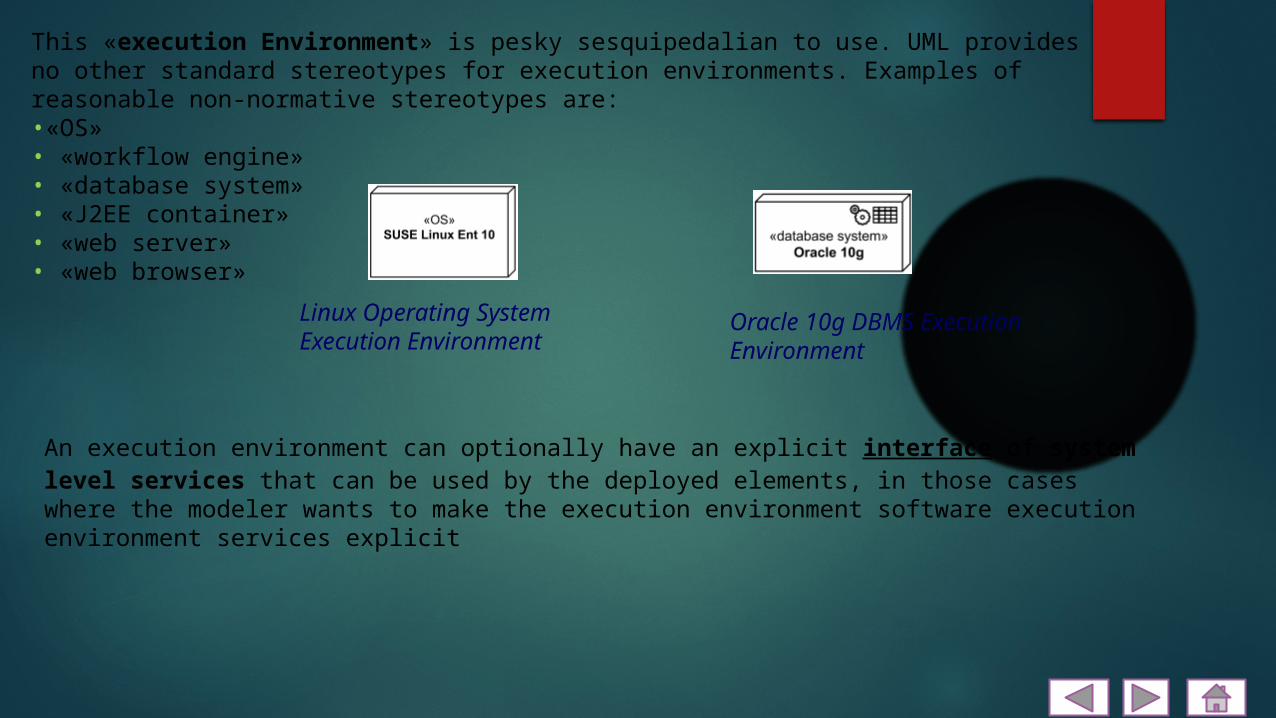
This «execution Environment» is pesky sesquipedalian to use. UML provides no other standard stereotypes for execution environments. Examples of reasonable non-normative stereotypes are:•«OS»• «workflow engine»• «database system»• «J2EE container»• «web server»• «web browser»
Linux Operating System Execution Environment
Oracle 10g DBMS Execution Environment
An execution environment can optionally have an explicit interface of system level services that can be used by the deployed elements, in those cases where the modeler wants to make the execution environment software execution environment services explicit
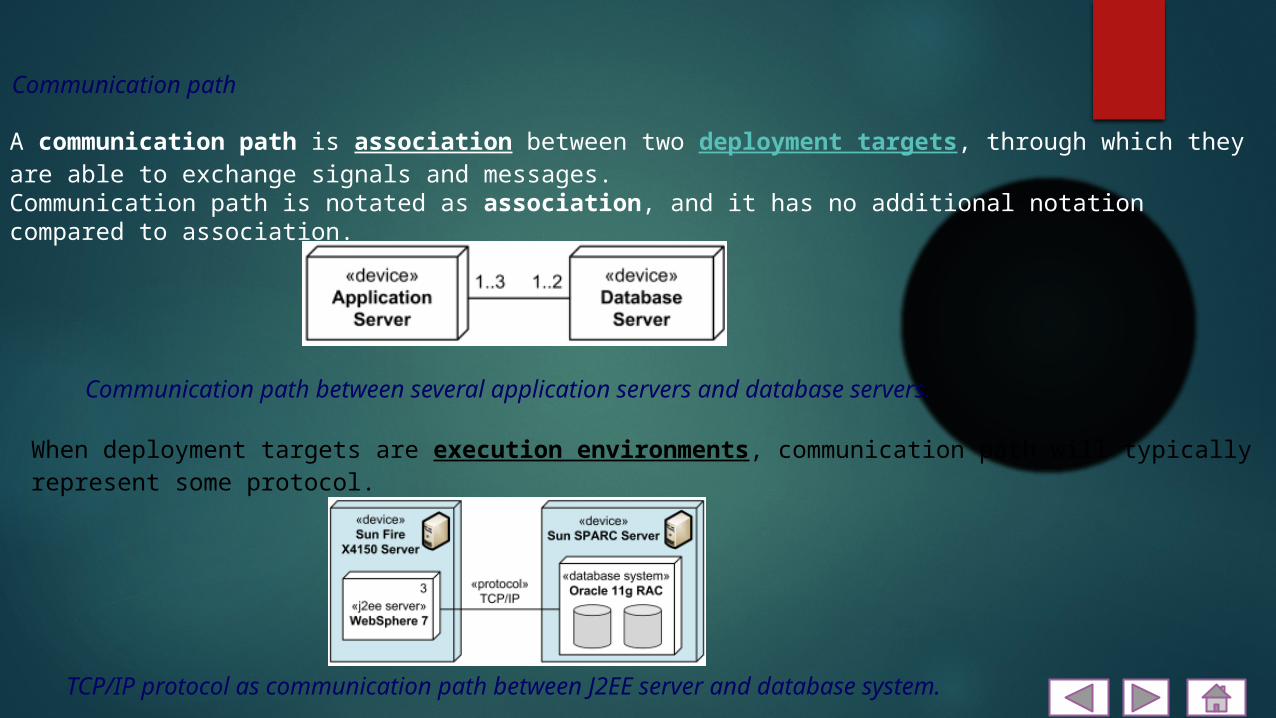
A communication path is association between two deployment targets, through which they are able to exchange signals and messages.Communication path is notated as association, and it has no additional notation compared to association.
Communication path between several application servers and database servers.
When deployment targets are execution environments, communication path will typically represent some protocol.
TCP/IP protocol as communication path between J2EE server and database system.
Communication path

A deployment is a dependency relationship which describes allocation (deployment) of an artifact to a deployment target. Deployment could be also defined at instance level - as allocation of specific artifact instance to the specific instance of deployment target.A component deployment is deployment of one or more artifacts or artifact instances, optionally parameterized by a deployment specification.It is not very clear why UML defines deployment as a dependency, and not as an association or just a directed relationship. The major contradiction is that dependency in UML does not have any runtime implications, and is defined in terms of the model elements, not in terms of their instances. At the same time UML 2.4 allows and shows examples of instances of artifacts deployed to instances of nodes.Deployment could be shown as a dependency that is drawn from the artifact (supplier) to the deployment target (client) and is labeled with «deploy». Note, that dependency usually points from the client to the supplier, i.e. in the direction opposite to what is recommended by UML 2.4 for deployment. On the other hand, UML specification allows to change direction for a dependency based on user's stipulations.
Deployment
J2EE web application archive portfolio. wardeployed on Apache Tomcat JSP server.

Relationship is an abstract element which represents a concept of some kind of relationship between UML elements.A relationship references one or more related elements.There is no general notation for a relationship. In most cases the notation is some kind of a line connecting related elements. Specific subclasses of the relationship define their own notation.Subclasses of relationship are:•association,•directed relationship.Semantic Relationship?Though UML specifications (UML 1.3 to UML 2.4) use term semantic relationship in few places, they provide neither definition nor explanation of the term. There is no glossary in UML specifications since UML 2.0, so we may only guess meaning of many fancy terms UML specifications use.UML 1.x categorized association, constraint and dependency as a semantic relationship. UML User Guide book at about the same time defined association as a structural relationship.Since UML 2.0, only association is still categorized as semantic relationship by UML specification, while constraint became packageable element and dependency is now supplier/client relationship. IBM/Rational website defines association as both structural and semantic relationship where "semantic" means that there could be "connections among ... instances" and "structural" - that "objects of one thing are connected to objects of another thing. My wireless mouse has a link to my computer but it is not structural part of that computer. On the other hand, structural relationship could mean simply a relationship used on the structure diagram..
Relationship
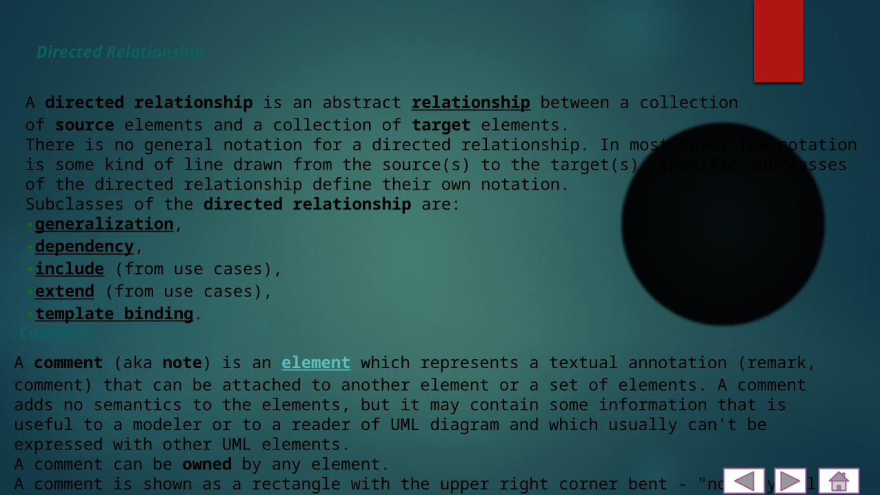
A directed relationship is an abstract relationship between a collection of source elements and a collection of target elements.There is no general notation for a directed relationship. In most cases the notation is some kind of line drawn from the source(s) to the target(s). Specific subclasses of the directed relationship define their own notation.Subclasses of the directed relationship are:•generalization,•dependency,•include (from use cases),•extend (from use cases),•template binding.
Directed Relationship
A comment (aka note) is an element which represents a textual annotation (remark, comment) that can be attached to another element or a set of elements. A comment adds no semantics to the elements, but it may contain some information that is useful to a modeler or to a reader of UML diagram and which usually can't be expressed with other UML elements.A comment can be owned by any element.A comment is shown as a rectangle with the upper right corner bent - "note symbol". The rectangle contains the body of the comment. Comment is connected to each annotated element by a dashed line.
Comment

Comment explaining clinical document and its relationship to patient
The dashed line connecting the comment to the annotated element(s) may be suppressed if it is clear from the context, or not important in the diagram.

A deployment specification is an artifact that specifies a set of deployment properties that determine execution parameters of a component artifact that is deployed on a node. A deployment specification can be aimed at a specific type of container for components.A deployment specification is a general mechanism to parameterize a deployment relationship, as is common in various hardware and software technologies. The deployment specification element is expected to be extended in specific component profiles. Non-normative examples of the standard stereotypes that a profile might add to deployment specification are, for example, «concurrency Mode» with tagged values {thread, process, none}, or «transaction Mode» with tagged values {transaction, nested Transaction, none}.A deployment specification at specification level is rendered as a classifier rectangle with optional deployment properties in a compartment.
The ejb-jar.xml deployment specification
Deployment Specification
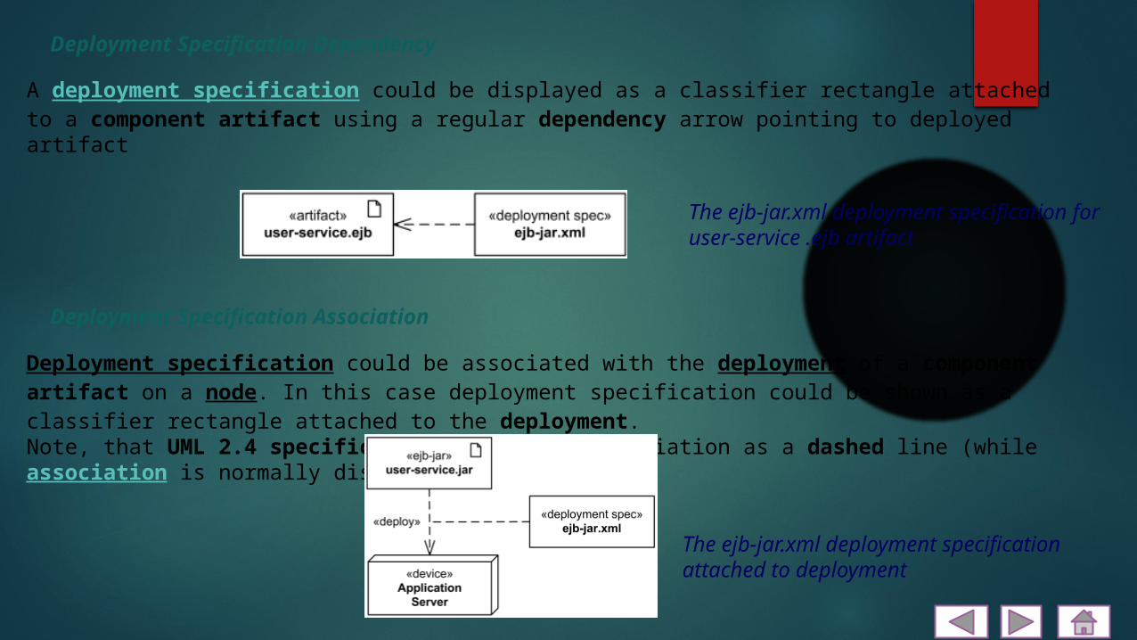
A deployment specification could be displayed as a classifier rectangle attached to a component artifact using a regular dependency arrow pointing to deployed artifact
Deployment Specification Dependency
Deployment Specification Association
Deployment specification could be associated with the deployment of a component artifact on a node. In this case deployment specification could be shown as a classifier rectangle attached to the deployment.Note, that UML 2.4 specification shows this association as a dashed line (while association is normally displayed as solid line.)
The ejb-jar.xml deployment specification attached to deployment
The ejb-jar.xml deployment specification for user-service .ejb artifact

UML ArtifactAn artifact is a classifier that represents some physical entity, a piece of information that is used or is produced by a software development process, or by deployment and operation of a system. Artifact is a source of a deployment to a node. A particular instance (or "copy") of an artifact is deployed to a node instance.Some real life examples of UML artifacts are:•text document•source file•script•binary executable file•archive file•database tableThe UML Standard Profile defines several standard stereotypes that apply to artifacts:
«file» A physical file in the context of the system developed
«document» A generic file that is not a «source» file or «executable».«source» A source file that can be compiled into an executable file.«library» A static or dynamic library file.«executable» A program file that can be executed on a computer system.«script» A script file that can be interpreted by a computer system.
Standard UML 1.x stereotype that is now obsolete:
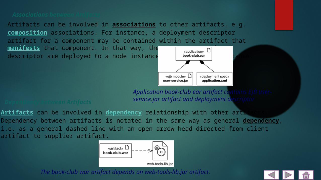
Artifacts can be involved in associations to other artifacts, e.g. composition associations. For instance, a deployment descriptor artifact for a component may be contained within the artifact that manifests that component. In that way, the component and its descriptor are deployed to a node instance as one artifact instance.
Associations between Artifacts
Dependency between ArtifactsArtifacts can be involved in dependency relationship with other artifacts.Dependency between artifacts is notated in the same way as general dependency, i.e. as a general dashed line with an open arrow head directed from client artifact to supplier artifact.
Application book-club ear artifact contains EJB user-service.jar artifact and deployment descriptor
The book-club war artifact depends on web-tools-lib.jar artifact.

Reference1.Jump up^ Deployment diagrams show "the allocation of Artifacts to Nodes according to the Deployments defined between them." Unified Modeling Language, Superstructure, V2.1.2 p. 202. •Introduction to UML 2 Deployment Diagrams by Scott W. Ambler•UML 2 Deployment Diagram•UML Deployment Diagrams

THANK YOU