Embed Size (px)
DESCRIPTION
Longwall 2014
Citation preview

Overview | |Challenges Enabling Technologies | Solution | Looking to the Future
Longwall 2014 – Hunter Valley, October 2014
Dr David C. Reid
CSIRO Principal Research Engineer
CSIRO ENERGY FLAGSHIP
Longwall and Continuous Miner automation

LASC – longwall automation technology
Overview | |Challenges Enabling Technologies | Solution | Looking to the Future
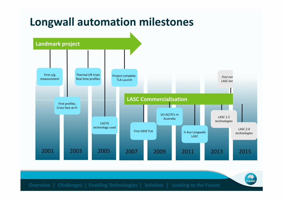
Longwall automation milestones
First u/g
measurement
First u/g
measurementFirst non-Aus
LASC longwall
First non-Aus
LASC longwall
Project complete.
TLA Launch
Project complete.
TLA Launch
LASC Commercialisation
Thermal I/R trials
Real time profiles
Thermal I/R trials
Real time profiles
Landmark project
Overview | |Challenges Enabling Technologies | Solution | Looking to the Future
20092003 2005 2007 201320112001
First profiles.
Cross face wi-fi.
First profiles.
Cross face wi-fi.
½ Aus Longwalls
LASC
½ Aus Longwalls
LASC
LN270
technology used
LN270
technology usedFirst OEM TLA First OEM TLA
LASC Commercialisation
2015
LASC 1.5
technologies
LASC 1.5
technologies
10 LN270’s in
Australia
10 LN270’s in
Australia
LASC 2.0
technologies
LASC 2.0
technologies
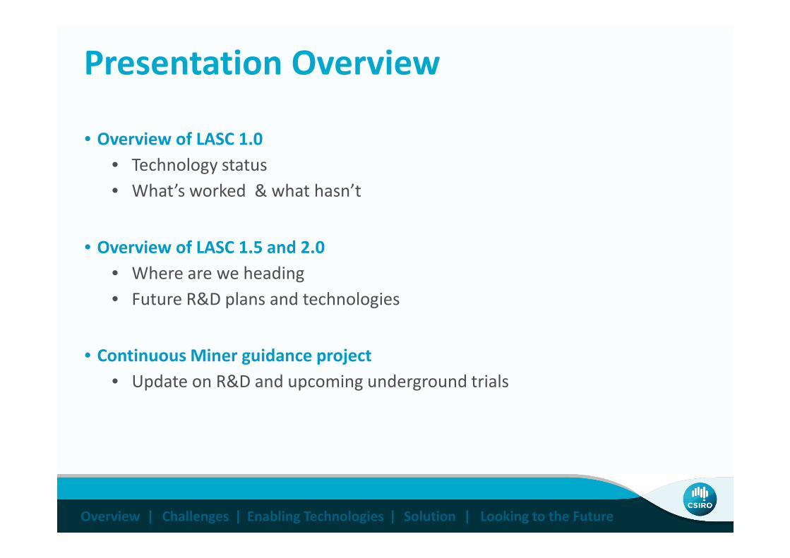
Presentation Overview
• Overview of LASC 1.0
• Technology status
• What’s worked & what hasn’t
• Overview of LASC 1.5 and 2.0
• Where are we heading
Overview | |Challenges Enabling Technologies | Solution | Looking to the Future
• Where are we heading
• Future R&D plans and technologies
• Continuous Miner guidance project
• Update on R&D and upcoming underground trials
V-axis:Straightening
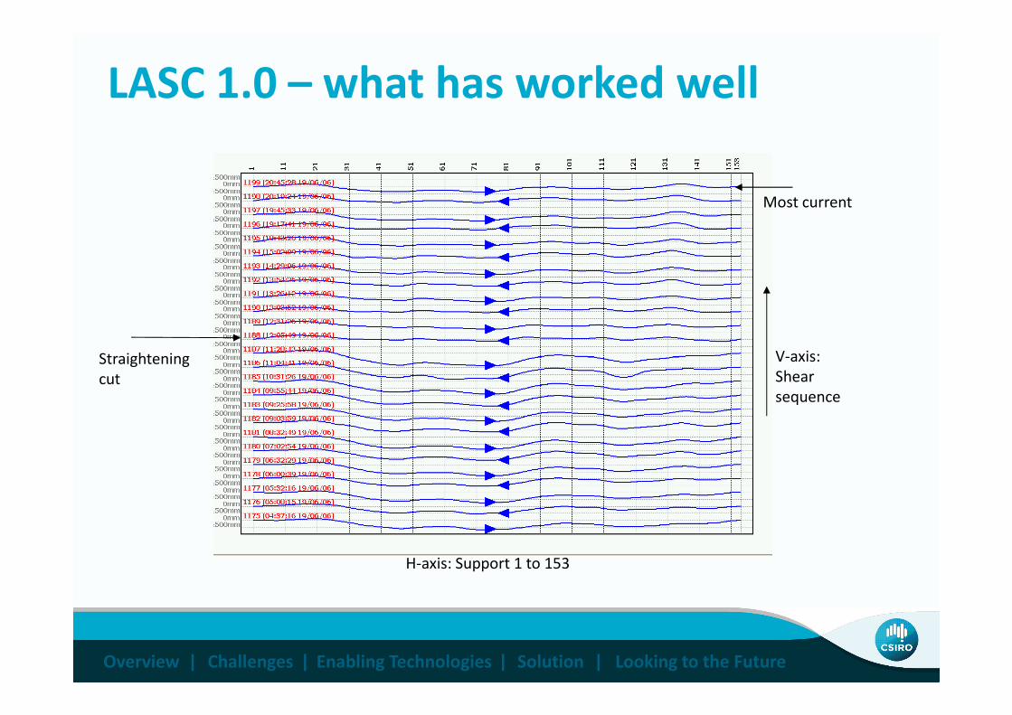
Most current
LASC 1.0 – what has worked well
Overview | |Challenges Enabling Technologies | Solution | Looking to the Future
H-axis: Support 1 to 153
V-axis:
Shear
sequence
Straightening
cut
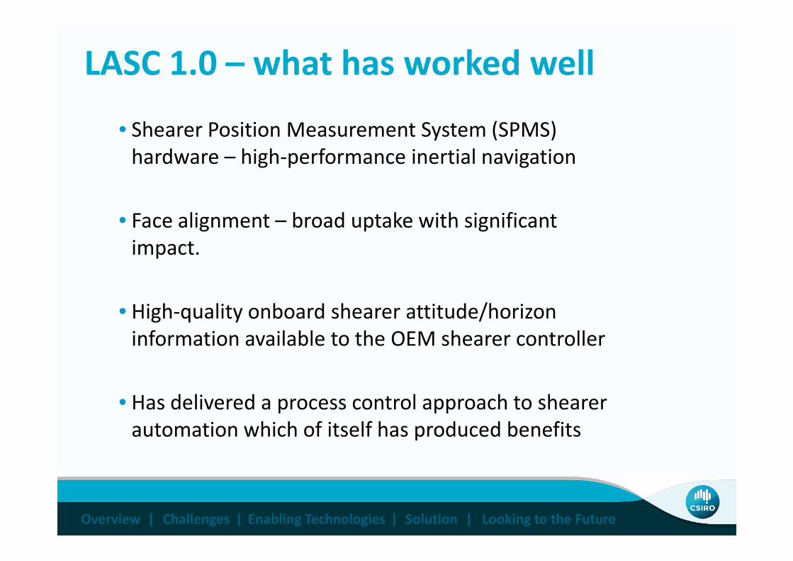
LASC 1.0 – what has worked well
• Shearer Position Measurement System (SPMS)
hardware – high-performance inertial navigation
• Face alignment – broad uptake with significant
impact.
Overview | |Challenges Enabling Technologies | Solution | Looking to the Future
• High-quality onboard shearer attitude/horizon
information available to the OEM shearer controller
• Has delivered a process control approach to shearer
automation which of itself has produced benefits

LASC 1.0 – where are the main gaps
• Creep/retreat – an old chestnut that still needs some
cracking
• Horizon control that has general applicability. LASC 1.0
has provided a solid platform but not the full solution
Overview | |Challenges Enabling Technologies | Solution | Looking to the Future
• Need for active seam tracking for improved horizon
control
• LASC software/system configuration and management
tools too complicated

LASC 1.5 – what have we been working on
• Major rewrite of LASC server software • Simplified installation, commissioning and configuration
• Consolidate and reduce the number of software modules to reduce
complexity
• Support for a range of databases (not just MySQL) via ODBC interface
• Improved operator screens including database interface .
Overview | |Challenges Enabling Technologies | Solution | Looking to the Future
• ITAR-free Inertial Navigation System• LASC support for non-ITAR inertial navigation hardware
• Non-ITAR INS has been successfully trialled in Australia. This INS can be
exported to ITAR-restricted countries.
• Made available to the industry via the LASC longwall OEMs

LASC 2.0 – where to next
• The Mining Technology Research Group continues to undertake
strategic research into new LASC-related technologies
• We are actively seeking feedback from those in the industry
with LASC experience to chart a course for next generation
LASC developments
• Learnings from LASC1.0 experience
Overview | |Challenges Enabling Technologies | Solution | Looking to the Future
• Learnings from LASC1.0 experience
• Review and input into the CSIRO 2, 5 & 10 year technology
development roadmap

LASC 2.0 – technology roadmap
Overview | |Challenges Enabling Technologies | Solution | Looking to the Future
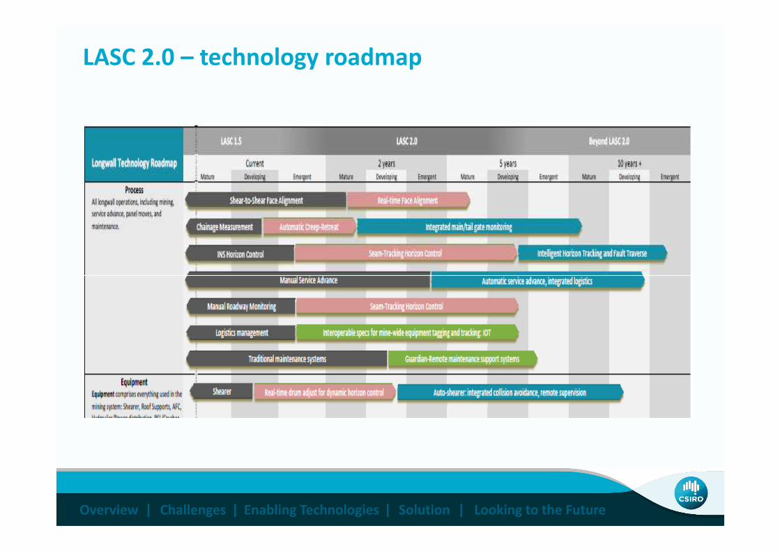
LASC 2.0 – technology roadmap
Overview | |Challenges Enabling Technologies | Solution | Looking to the Future

LASC 2.0 – some specific technologies
• Active seam tracking• Optical and thermal marker band
• CSIRO interest is in image/data processing and LASC integration
• System simplification• Onboard shearer (SPMS) data processing
• Remove surface database and services from control loop
• Simplify installation, commissioning and configuration
Overview | |Challenges Enabling Technologies | Solution | Looking to the Future
• Simplify installation, commissioning and configuration
• Real time FA and HC data• Reduce LASC response cycle times (presently up to 3 shear cycles)
• Creep/retreat (and more)• New scanning laser technology
• CSIRO-developed transparent panoramic flameproof enclosure (current
ACARP project - provisional patent)
• Laser/enclosure has broader applicability
3D scanning laser – panoramic flameproof enclosureFor longwall creep/retreat measurement and more
Overview | |Challenges Enabling Technologies | Solution | Looking to the Future
CM Guidance project update
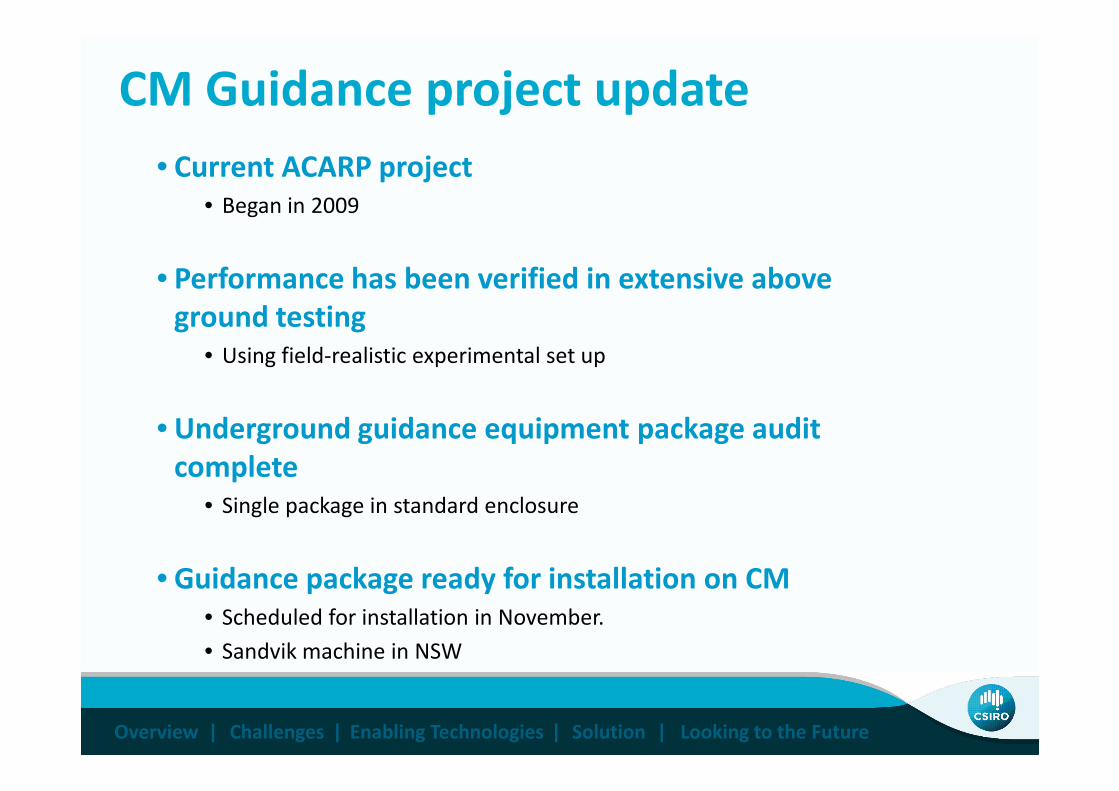
• Current ACARP project
• Began in 2009
• Performance has been verified in extensive above
ground testing
• Using field-realistic experimental set up
Overview | |Challenges Enabling Technologies | Solution | Looking to the Future
• Underground guidance equipment package audit
complete
• Single package in standard enclosure
• Guidance package ready for installation on CM
• Scheduled for installation in November.
• Sandvik machine in NSW

Solution: Test Platform – The Phoenix
Overview | |Challenges Enabling Technologies | Solution | Looking to the Future

Ebenezer Experimental Test Site
Overview | |Challenges Enabling Technologies | Solution | Looking to the Future

CM Guidance performance
• Performance
• 30cm maximum cross track error over 2.7km, 2.5hr “two heading
roadway” mission – repeated experiments at Ebenezer test site
• Communications
• An open-system data communications specification has been developed
to ensure interoperability across multi-vendor mining equipment
Overview | |Challenges Enabling Technologies | Solution | Looking to the Future

Approved equipment arrangement
Compact equipment rack to suit ATF950 enclosure
Overview | |Challenges Enabling Technologies | Solution | Looking to the Future

Approved equipment arrangement
Compact equipment rack to suit ATF950 enclosure
Overview | |Challenges Enabling Technologies | Solution | Looking to the Future

On-machine guidance display
Overview | |Challenges Enabling Technologies | Solution | Looking to the Future

CM Guidance project update
• Current underground testing will proceed with
guidance system in “monitoring only” mode • Instantaneous pointing and tilt information can be made available
via on-machine graphical display
• Logged data will be compared mine survey information over an
expended period to establish confidence and performance measure
Overview | |Challenges Enabling Technologies | Solution | Looking to the Future
• Subsequently data can be made available to the
miner controller for steering control
• Required OEM development and cooperation
• Final stage to close the control loop on full navigation • Automated roadway alignment (and cut-throughs etc)

Thank you
Overview | |Challenges Enabling Technologies | Solution | Looking to the Future
Thank youDr David C. Reid
Principal Research Engineer
Mining Technology Research Group
t +61 7 3327 4437e [email protected]

![ASKAP Status Update CSIRO ASTRONOMY AND SPACE SCIENCE David Brodrick EPICS [Spring] Collaboration Meeting 22nd October 2014](https://img.dokumen.tips/doc/110x75/56649cb15503460f949762ac/askap-status-update-csiro-astronomy-and-space-science-david-brodrick-epics.jpg)