Embed Size (px)
Citation preview
ELECTRICAL ELECTRONICS COMMUNICATION INSTRUMENTATION
Control Systems
Signal Flow graphs

ELECTRICAL ELECTRONICS COMMUNICATION INSTRUMENTATION
Introduction
• Block diagram is a pictorial representation of the sequence of events in a process
• For complicated systems difficult to reduce block diagrams
• Signal flow graph – a graphical representation of the relationship between variables – Provides relationship between system variables
without the need for reduction

ELECTRICAL ELECTRONICS COMMUNICATION INSTRUMENTATION
Signal Flow Graph (SFG)
Block Diagram to signal flow graph

ELECTRICAL ELECTRONICS COMMUNICATION INSTRUMENTATION
Signal Flow Graph (SFG)
• A signal-flow graph is a diagram consisting of
nodes that are connected by several directed
branches and is a graph representation of a set of
linear relation.• Only valid for linear system

ELECTRICAL ELECTRONICS COMMUNICATION INSTRUMENTATION
Basic elements of SFG
• Branch: A unidirectional path segment
• Nodes: The input and output points or
junctions

ELECTRICAL ELECTRONICS COMMUNICATION INSTRUMENTATION
Basic elements of SFG
Input Node Output NodeMixed Node

ELECTRICAL ELECTRONICS COMMUNICATION INSTRUMENTATION
• Path: A branch or a continuous sequence of branches
that can be traversed from one node to anther node.
Basic elements of SFG
1. Forward Path2. Feedback path

ELECTRICAL ELECTRONICS COMMUNICATION INSTRUMENTATION
• Loop: A closed path that originates and terminates on the same node, and along the path no node is met twice.
Basic elements of SFG

ELECTRICAL ELECTRONICS COMMUNICATION INSTRUMENTATION
• Non-touching loops: If two loops do not have a common node.
Basic elements of SFG

ELECTRICAL ELECTRONICS COMMUNICATION INSTRUMENTATION
Touching loops: Two touching loops share one or more common nodes.
Basic elements of SFG

ELECTRICAL ELECTRONICS COMMUNICATION INSTRUMENTATION
Self loop: Path that originates and terminates at the same node.
Basic elements of SFG

ELECTRICAL ELECTRONICS COMMUNICATION INSTRUMENTATION
Basic elements of SFG
1. Forward Path Gain: P1 = G1G2G3
P2 = G4
P3 = G1G2(-1)

ELECTRICAL ELECTRONICS COMMUNICATION INSTRUMENTATION
2. Feedback Path Gain: -G1H1
Basic elements of SFG
In this case there is one loop or Feed back path

ELECTRICAL ELECTRONICS COMMUNICATION INSTRUMENTATION
Basic elements of SFG
3. Non-touching loop gain: Two Non-touching loops gain: G2H2H3
G2H2H7G7
G7H7H3
Three Non-touching loops gain: G2H2H3H7G7
ELECTRICAL ELECTRONICS COMMUNICATION INSTRUMENTATION
Basic elements of SFG
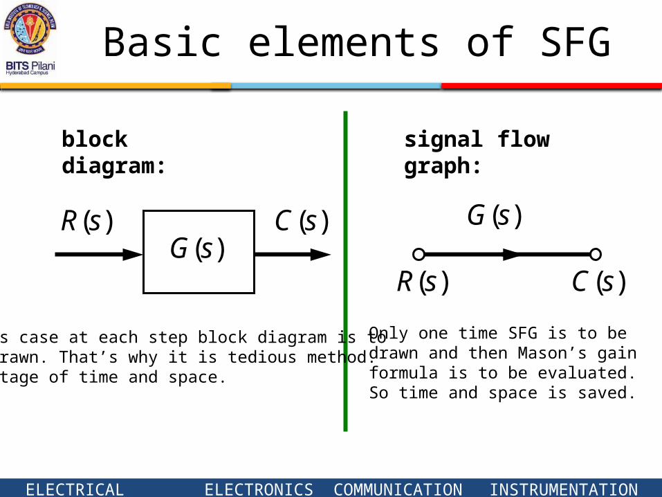
)(sR)(sG
)(sC )(sG
)(sR )(sC
block diagram: signal flow graph:
In this case at each step block diagram is to be redrawn. That’s why it is tedious method.So wastage of time and space.
Only one time SFG is to be drawn and then Mason’s gain formula is to be evaluated.So time and space is saved.

ELECTRICAL ELECTRONICS COMMUNICATION INSTRUMENTATION
Block Diagram to SFG

ELECTRICAL ELECTRONICS COMMUNICATION INSTRUMENTATION
Block Diagram to SFG

ELECTRICAL ELECTRONICS COMMUNICATION INSTRUMENTATION
G4(s)
Block Diagram to SFG
E(s) x1 (s) x2 (s) Y(s)
-H1(s)
G1(s) G2(s) G3(s)
-1
R(s)
1

ELECTRICAL ELECTRONICS COMMUNICATION INSTRUMENTATION
Block Diagram to SFG

ELECTRICAL ELECTRONICS COMMUNICATION INSTRUMENTATION
Block Diagram to SFG

ELECTRICAL ELECTRONICS COMMUNICATION INSTRUMENTATION
Mason’s gain formula
The linear dependence (Gain) T i j between input variable x i and output variable x j is given by the following formula:
k ijkijk
ij
PT

ELECTRICAL ELECTRONICS COMMUNICATION INSTRUMENTATION
Mason’s Gain Rule
Mason’s gain rule is as follows: the transfer function of a system with signal-input, signal-output flow graphs is
332211)(
pppsT
Δ=1-(sum of all loop gains)+(sum of products of gains of all combinations if 2 non-touching loops)- (sum of products of gains of all combinations if 3 non-touching loops)+…
A path is any succession of branches, from input to output, in the direction of the arrows, that does not pass any node more than once.
A loop is any closed succession of branches in the direction of the arrows that does not pass any node more than once.

ELECTRICAL ELECTRONICS COMMUNICATION INSTRUMENTATION
Ex 1: Signal-Flow Graph Models

ELECTRICAL ELECTRONICS COMMUNICATION INSTRUMENTATION
P 1 = G1G2G3G4 P 2 = G5G6G7G8
Ex 1: Signal-Flow Graph Models

ELECTRICAL ELECTRONICS COMMUNICATION INSTRUMENTATION
Individual loops
L 1 = G2 H2
L 4 = G7 H7
L 3 = G6 H6
L 2= G3 H3
Pair of Non-touching loops L 1L 3 L 1L 4
L2 L3 L 2L 4
Ex 1: Signal-Flow Graph Models

ELECTRICAL ELECTRONICS COMMUNICATION INSTRUMENTATION
..)21(1( LiLjLkiLjLLL
P
R
Y kk
Y s( )
R s( )
G 1 G 2 G 3 G 4 1 L 3 L 4 G 5 G 6 G 7 G 8 1 L 1 L 2
1 L 1 L 2 L 3 L 4 L 1 L 3 L 1 L 4 L 2 L 3 L 2 L 4
Ex 1: Signal-Flow Graph Models

ELECTRICAL ELECTRONICS COMMUNICATION INSTRUMENTATION
Ex 2: SFG

ELECTRICAL ELECTRONICS COMMUNICATION INSTRUMENTATION
Ex 2: SFG
Forward Paths
P1 = G1G2G3G4G5G6
P2 = G1G2G7G6
P3 = G1G2G3G4G8

ELECTRICAL ELECTRONICS COMMUNICATION INSTRUMENTATION
L 3 = -G 8 H 1
LOOPS
L 2 = -G2 G 3G 4G 5 H2
Ex 2: SFG

ELECTRICAL ELECTRONICS COMMUNICATION INSTRUMENTATION
L 4 = - G2 G 7 H2
L5 = -G 4 H 4
L1= -G 5 G 6 H 1
LOOPS
Ex 2: SFG

ELECTRICAL ELECTRONICS COMMUNICATION INSTRUMENTATION
L 7 = - G 1G2 G 7G 6 H3
L 6 = - G 1G2 G 3G 4G 8 H3
L 8= - G 1G2 G 3G 4G 5 G 6 H3
Ex 2: SFGLOOPS

ELECTRICAL ELECTRONICS COMMUNICATION INSTRUMENTATION
Ex 2: SFG
Pair of 2 non-touching loops

ELECTRICAL ELECTRONICS COMMUNICATION INSTRUMENTATION
Pair of Non-touching loops
L 4
L 5
L 3L 7
L 4
L 5L 7
L 4L 5
L 3L 4

ELECTRICAL ELECTRONICS COMMUNICATION INSTRUMENTATION
Non-touching loops for paths
∆ 1 = 1∆ 2= -G 4 H4
∆ 3= 1

ELECTRICAL ELECTRONICS COMMUNICATION INSTRUMENTATION
Signal-Flow Graph Models
Y s( )
R s( )
P1 P2 2 P3
P1 G1 G2 G3 G4 G5 G6 P2 G1 G2 G7 G6 P3 G1 G2 G3 G4 G8
1 L1 L2 L3 L4 L5 L6 L7 L8 L5 L7 L5 L4 L3 L4
1 3 1 2 1 L5 1 G4 H4

ELECTRICAL ELECTRONICS COMMUNICATION INSTRUMENTATION
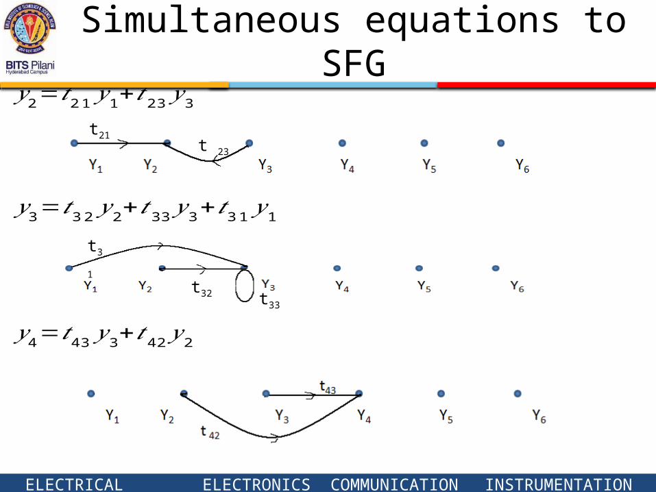
Simultaneous equations to SFG
𝑦 2=𝑡 21 𝑦1+𝑡 23 𝑦3𝑦 3=𝑡 32 𝑦2+𝑡33 𝑦 3+𝑡31 𝑦1𝑦 4=𝑡43 𝑦 3+𝑡42 𝑦2
𝑦 5=𝑡 54 𝑦4𝑦 6=𝑡 65 𝑦5+𝑡 64 𝑦4
ELECTRICAL ELECTRONICS COMMUNICATION INSTRUMENTATION
t21t 23
t31
t32 t33
𝑦 2=𝑡 21 𝑦1+𝑡 23 𝑦3
𝑦 3=𝑡 32 𝑦2+𝑡33 𝑦 3+𝑡31 𝑦1
𝑦 4=𝑡43 𝑦 3+𝑡42 𝑦2
Simultaneous equations to SFG

ELECTRICAL ELECTRONICS COMMUNICATION INSTRUMENTATION
𝑦 5=𝑡 54 𝑦4
𝑦 6=𝑡 65 𝑦5+𝑡 64 𝑦4
Simultaneous equations to SFG

ELECTRICAL ELECTRONICS COMMUNICATION INSTRUMENTATION
After joining all SFG