Embed Size (px)
Citation preview

CNC FEED DRIVESAkhil Krishnan G
M.Tech
1

CONTENTS
1.Introduction
2.Requirements of CNC feed drives
3.Servo motor
3.1 Servo drive control
3.2 Components of servo controlled cnc.
3.3 servo-drive control
4.DC Servo Motor
5. AC Servo Motor
6.Comparison between D.C. And A.C. Servomotor
7. Stepping Motor
7.1 Construction
7.2 Working
7.3 Advantages
7.4 Disadvantages
8.Reference2

1.INTRODUCTION
The driving system is an important component of a CNC machine as
the accuracy and repeatability depend very much on the characteristics
and performance of the driving system.
The driving system is classified as spindle drives and feed drives.
The spindle drives are used to provide angular motion to the work
piece or a cutting tool.
The feed drives are used to drive the slide or a table.
The feed drive consists of an electromotor and mechanical
transmission elements.3

4
Fig 2.Working principle of CNC feed drive
Fig 1.working principle of spindle drives

o This system usually uses electric motors although hydraulic motors
are sometimes used for large machine tools.
Electric Motors
o An electric motor is an electric machine that converts electrical
energy into mechanical energy
o Most electric motors operate through the interaction between an
electric motor's magnetic field and winding currents to generate
force within the motor.
Hydraulic motor
o A hydraulic motor is a mechanical actuator that converts hydraulic
pressure and flow into torque and angular displacement (rotation)5
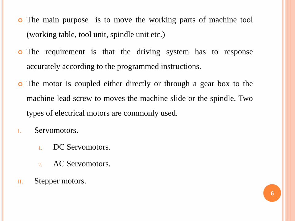
The main purpose is to move the working parts of machine tool
(working table, tool unit, spindle unit etc.)
The requirement is that the driving system has to response
accurately according to the programmed instructions.
The motor is coupled either directly or through a gear box to the
machine lead screw to moves the machine slide or the spindle. Two
types of electrical motors are commonly used.
I. Servomotors.
1. DC Servomotors.
2. AC Servomotors.
II. Stepper motors.
6

2.REQUIREMENTS OF CNC FEED DRIVES.
High torque-to-weight ratio
Low armature or rotor inertia
Low electrical and mechanical time constants
Permanent magnet construction
Maximum speed up to 3000rpm
High peak torque for quick response
The required constant torque for overcoming frictional and
working force must be provided. 7

3.SERVO MOTOR
o Positions mechanical elements within a given time and with a given
precision.
o Operates at low power ranges.
o Factors to be considered in servo action are :
o Dynamics
o Position exactness
o Peak torque
o Speed regulation range etc
8

3.1 SERVO DRIVE CONTROL
9

3.2 COMPONENTS OF SERVO CONTROLLED CNC
10
Motor speed control
Motor lead screw rotation table moves
position sensed by encoderfeedback

3.3 SERVO-DRIVE CONTROL
Working of a servo motor :
o The desired position is given as input to the system. The actual
position is measured by the encoder is given to position controller as
feedback.
o This results in the desired speed which is compared with actual speed
feedback by the Tachogenerator.
o This comparison gives out the output of the desired current to be
compared with the feedback of actual current.
o The current controller gives the output of control voltage to the
motor.
o A six pulse-bridge supplied with a 3-phase system gives the direct
voltage depending on the control voltage.
11

4.DC SERVO MOTOR
This is the most common type of feed motors used in CNC machines
The principle of operation is based on the rotation of an armature winding in
a permanently energized magnetic field.
The armature winding is connected to a commutator, which is a cylinder of
insulated copper segments mounted on the shaft
DC current is passed to the commutator through carbon brushes, which are
connected to the machine terminals.
The change of the motor speed is by varying the armature voltage and the
control of motor torque is achieved by controlling the motor's armature
current.
In order to achieve the necessary dynamic behavior it is operated in a closed
loop system equipped with sensors to obtain the velocity and position
feedback signals.12

4.1 FEATURES OF DC SERVOMOTOR
o Smooth rotation at speed less than one rpm.
o Bush life of more than 4000 rpm.
o Sensor less switching.
o Transistor controller and diode rectifier.
o Resolver for speed control and position control and switching
control.
o Resolver ® performs the task of both tachogenerator and pulse-
generator (p-encoder).
13

14
Fig 3.Working of DC Servomotor

15
Fig4. Control of DC Servomotor

5. AC SERVO MOTOR
In an AC servomotor, the rotor is a permanent magnet while the
stator is equipped with 3-phase windings
The speed of the rotor is equal to the rotational frequency of the magnetic
field of the stator, which is regulated by the frequency converter.
AC motors are gradually replacing DC servomotors
The main reason is that there is no commutator or brushes in AC servomotor
so that maintenance is virtually not required
Furthermore, AC servos have a smaller power-to-weight ratio and faster
response.
16

17
Fig 5.Working principle of AC Servo motor
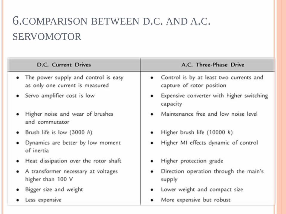
6.COMPARISON BETWEEN D.C. AND A.C.
SERVOMOTOR
18

7. STEPPING MOTOR
A stepping motor is a device that converts the electrical pulses
into discrete mechanical rotational motions of the motor shaft
This is the simplest device that can be applied to CNC machines
since it can convert digital data into actual mechanical displacement
19

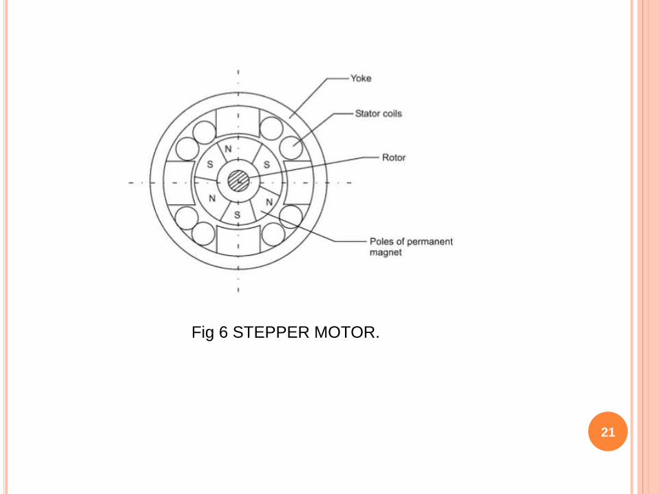
7.1 CONSTRUCTION
o Stator has a winding made of concentrated coils on distinct poles.
o Rotor has a permanent magnet cylinder.
o The stator windings are inserted on the periphery of the yoke and this
is slide on the permanent magnet pole cylinder.
o The rotor shaft is located at the center of the yoke, mounted on
bearings
o Examples of stepping motor application are the magnetic head of
floppy-disc drive and hard disc drive of computer, daisy-wheel type
printer, X-Y tape control, and CNC EDM Wire-cut machine
20
21
Fig 6 STEPPER MOTOR.

7.2 WORKING
22
The rotation of the magnet inside the yoke will
energize the poles
Fig 7 working of stepper motor

7.3 ADVANTAGES
o It is not necessary to have any analog-to-digital converter nor
feedback device for the control system. They are ideally suited to
open loop systems
o Low cost
o Ruggedness
o Simplicity in construction
o High reliability
o No maintenance
23

7.4 DISADVANTAGES
Slow speed
Low torque
Low resolution
Easy to slip in case of overload
24

8.REFERENCE
http://www.ignou.ac.in/
http://www.kimla.pl/en/feeddrives
http://nptel.ac.in/courses/112103174/pdf/mod4.pdf
http://accessengineeringlibrary.com/
http://electrical4u.com/electrical-drives/
25

26