Embed Size (px)
Citation preview
EE211: Circuit Analysis
Lecture: 10-12
Nodal Analysis
- Independent/Dependent Current Sources
-Independent Voltage Sources

Nodal Analysis
• The variables selected in the circuit are node voltages
• Node voltages are defined w.r.t to a common point in the circuit
• All voltages are defined w.r.t a reference node• All voltages are defined w.r.t a reference node• Quite often largest number of branches are
connected to this node and is called ground – it is said to be at ground-zero potential
• In most of the cases, the selected variables (voltages) will be positive w.r.t to the reference node
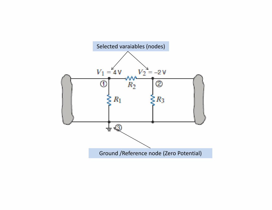
Selected varaiables (nodes)
Ground /Reference node (Zero Potential)

• In the figure all voltages are defined w.r.t to the bottom reference (ground) node
• Reference node is shown by the ground symbol• Vs, Va, Vb, Vc are measured w.r.t bottom node• The voltage across an element between two nodes is equal to
the difference between the voltages at those two nodes
– e.g; V3 = Va – Vb = 3– e.g; V3 = Va – Vb = 2

Or we can also use KVL →
The voltage at reference(ground) node is zero

I = ∆V/R
• Thus, as a general rule if we know the node voltages in a circuit, we can calculate the current throught any resistive element using Ohm’s law as:
Nm vvi
NRi

• In nodal analysis, KCL is employed such that– Variables in the equations are the unknown
voltages
• In an N-node circuit– One node is selected as reference node
– Voltages at non-reference nodes are measured w.r.t this reference node.
– N-1 linearly independent KCL equations are required to determine the N-1 unknown node voltages.
– It is always important to specify a reference

• Voltage of 12 V at node-A means nothing unless we specify 12 V w.r.tsome reference node
• Voltage at node-1 w.r.t reference node-3 is V1 = 4V• Voltage at node-2 w.r.t reference node-3 is V2 = -2V
– Voltage at node-1 w.r.t node-2 = ?– Voltage at node-2 w.r.t node-1 = ?
• Current flows from node of higher potential to node of lower potential
Top to bottom current flow Bottom to top current flow
Left to right current flow
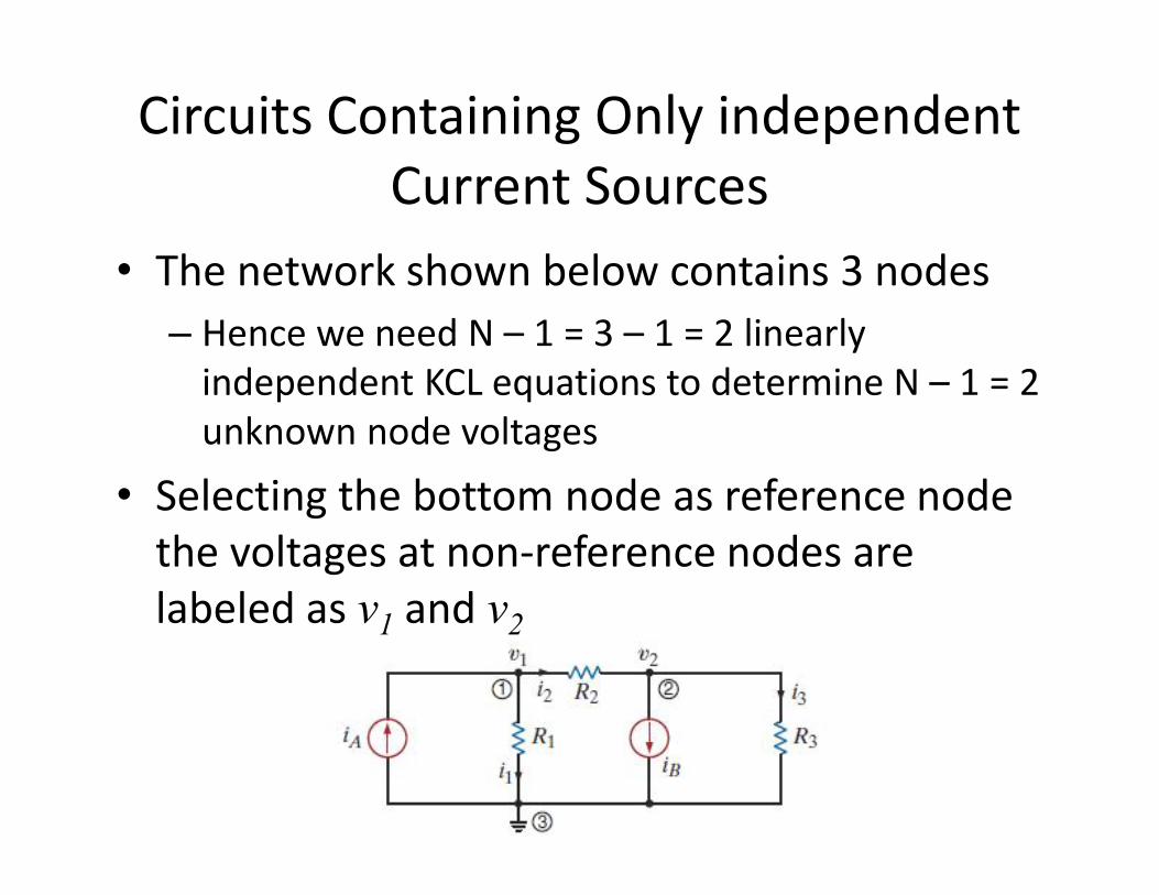
Circuits Containing Only independent Current Sources
• The network shown below contains 3 nodes
– Hence we need N – 1 = 3 – 1 = 2 linearly independent KCL equations to determine N – 1 = 2 unknown node voltagesunknown node voltages
• Selecting the bottom node as reference node the voltages at non-reference nodes are labeled as v1 and v2
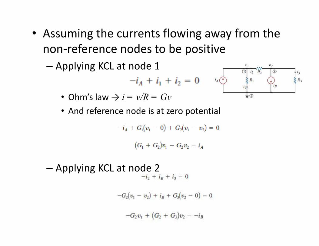
• Assuming the currents flowing away from the non-reference nodes to be positive
– Applying KCL at node 1
• Ohm’s law → i = v/R = Gv
• And reference node is at zero potential
– Applying KCL at node 2

• Hence, the two equations for the unknown node voltages are,
• The result is two simultaneous equations in unknowns v1 and v2
• Any circuit analysis technique can be used for solving these equationssolving these equations– Gaussian Elimination– Matrices– MATLAB
• Note that nodal analysis employs KCL in conjunction with Ohm’s law

Example 3.1, pg: 105
• Find all node voltages if
– IA = 1 mA, IB = 4 mA, R1 = 12 kΩ, R2 = 6 kΩ, R3 = 6 kΩ

Solving in MATLAB• The results of manual calculations can often be
checked through MATLAB, e.g; for a given case the following three commands can be used
• R = [2 3, 4 6]; //declares resistance matrix
• I = [ 0.001; 0.005]; //declares current matrix
• G = inv (R); //calculates the inverse of R matrix
• V = G*I or V = inv(R)*I //calculates the node voltages

Circuits with more than two non-reference nodes

• The analyses produces 3 simultaneous equationsequations– The equations can be written in matrix form as:
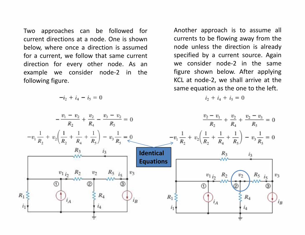
Another approach is to assume allcurrents to be flowing away from thenode unless the direction is alreadyspecified by a current source. Againwe consider node-2 in the samefigure shown below. After applyingKCL at node-2, we shall arrive at thesame equation as the one to the left.
Two approaches can be followed forcurrent directions at a node. One is shownbelow, where once a direction is assumedfor a current, we follow that same currentdirection for every other node. As anexample we consider node-2 in thefollowing figure.
Identical Equations

Example 3.2, pg: 109
• Find the node voltages in the following network if
– R1 = R2 = 2 kΩ, R3 = R4 = 4 kΩ, R5 = 1 kΩ, iA = 4 mAand iB = 2 mAand iB = 2 mA
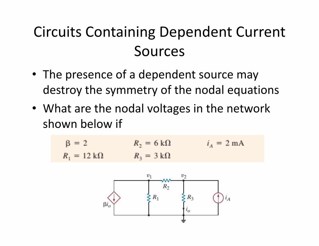
Circuits Containing Dependent Current Sources
• The presence of a dependent source may destroy the symmetry of the nodal equations
• What are the nodal voltages in the network shown below ifshown below if

Example 3.4, pg: 112
• Find the node voltages if
– R1 = 1 kΩ, R2 = R3 = 2 kΩ, R4 = 4 kΩ, iA = 2 mA, iB = 4 mA and α = 2

Circuits Containing Independent Voltage Sources
• In case of independent voltage sources, the equations will be symmetric
• In some cases, through careful observation, one or more nodal voltages might already be givenvoltages might already be given– This will reduce the number of nodal
equations required for finding the unknown voltages
– In the figure shown to the right, node voltages V1 and V3 are already known as both have a direct connection to the reference ground node • Thus only one equation is required to
solve for the unknown node voltage V2

Example 3.5, pg: 113
• Find V1, V2 and V3 in the following network using nodal analyses